U90 Ladder Software Manual
|
|
|
- Margaret Nash
- 6 years ago
- Views:
Transcription
1 U90 Ladder Software Manual 3/06
2
3 No part of this document may be used for any purpose other than for the purposes specifically indicated herein nor may it be reproduced or transmitted in any form or by any means, electronic or mechanical, including photocopying and/or recording, for any purpose without written permission from Unitronics. The information appearing in this document is for general purposes only. Unitronics makes no warranty of any kind with regard to the information appearing in this document, including, but not limited to, implied warranties of merchantability and/or fitness for a particular use or purpose. Unitronics assumes no responsibility for the results, direct and/or indirect, of any misuse of the information appearing in this document nor for any use of the Unitronics products referred to herein in any manner deviating from the recommendations made in this document. Unitronics assumes no responsibility for the use of any parts, components, or other ancillary appliances including circuitry other than as recommended hereunder or other than that embodied in the Unitronics product. Unitronics retains all rights to its proprietary assets including, but not limited to its software products which are copyrighted and shall remain the property of Unitronics. Copyright protection claimed includes all Forms and matters of copyrightable materials and information legally allowed including but not limited to material generated from the software programs which are displayed on the screen of the Unitronics products such as styles, templates, icons, screen displays, looks, etc. Duplication and/or any unauthorized use thereof are strictly prohibited without prior written permission from Unitronics. All brand or product names are used for identification purpose only and may be trademarks or registered trademarks of their respective holders. Unitronics reserves the right to revise this publication from time to time and to amend its contents and related hardware and software at any time. Technical updates (if any) may be included in subsequent editions (if any).
4
5 Table Of Contents Getting Started... 1 Opening a new project... 1 Opening a project... 1 Downloading a Project... 1 Uploading a Project... 3 Project Properties... 3 General... 4 Password... 5 History... 5 Statistics... 6 Set Logo Pic... 7 Ladder Editor... 7 Using the HMI Display Editor... 7 PLC Display Language... 8 How to identify Multilingual models... 9 Changing the PLC Display Language Comments Tool Deleting Comments Power-up Hardware Configuration Selecting the Controller Model Configuring I/O Expansion Modules Configuring I/Os: Linking Operands Addressing: I/O Expansion Modules Configuring Digital I/Os Configuring an Analog Input or Output Analog I/O Ranges Configuring a Thermocouple: M91 OPLC series High-Speed Counters (HSC), Shaft Encoders, Frequency Measurer...25 HSC Types & Functions Configuring a High-speed counter High-Speed Output: PWM M M Immediate: Read Inputs & HSC, Set/Reset Outputs M90/ Jazz Analog Input Value--Out Of Range Expansion modules M90 models M91 models HMI Display What is an HMI? What are Displays? Creating and Naming a Display Creating a fixed text Display v
6 U90 Ladder Software Manual Jump to Display: scrolling between Displays Changing a Display number Deleting a Display Changing a Jump condition Clearing a Display Clearing Jump conditions Creating more than four Jumps for a Display Display Formats for MI and SI Values Linearization Display the Time and Date on the LCD Displaying Special Symbols on the LCD Display Integer values as ASCII or Hexadecimal Scrolling between Displays via keypad Selecting a Timer Display format Toggling between Displays How many displays can I create? Variable Naming a Variable Creating Variables Showing an MI value on the controller's LCD List Variable: Display text according to a changing MI value Keypad Entry values How does the program know when a keypad entry is complete? Force: HMI Keypad Entry Complete, SB Converting Display values: Linearization Displaying an MI value with a leading zero Displaying text according to the value of a MB or SB Opening a Variable from a Display Selecting a Timer Display format Communications About Communications PLC Communication Settings PLC Parameters Advanced Settings Direct Communications- PC to PLC COM Port Mode: RS232/RS485 (M91 only) Setting the COM Port Mode Modems About Modems PC-Side Modems (Modem Services) Using a PC to access a PLC via GSM modem PLC-side Modems Modem Troubleshooting PLC modem communication problems Using Hyperterminal for Modem Troubleshooting PLC to Modem Connections and Pin-outs Modem Communications-- System Bits and Integers SMS vi
7 Table Of Contents About SMS messaging SMS Messaging Overview Configuring SMS messaging features Creating SMS messages Sending SMS messages from a GSM cell phone SMS Message Properties SMS phone book SMS Phone Number: via MI Pointer SMS System Bits, Integers, and Error Messages GSM PIN Code via MI Deleting SMS messages Using SMS messages in your application How the Controller works with SMS messaging SMS messaging problems Networks About M90/91 Networks Assigning a Unit ID number CANbus Networking Using your PC to access a network Ladder Ladder Logic Ladder Net Viewing Logic Power Flow in a net Ladder Nets with Feedbacks Deleting Nets Placing Contacts & Coils Placing a Function Block Connecting elements: Line Draw Intersecting lines: Junction Copy and Paste Elements Moving Elements Replacing Ladder elements Copying multiple nets Displaying an Operand Symbol in the Ladder Diagram Scrolling between nets Bookmarks Using Bookmarks Comments Elements U90 Ladder Elements Contacts Direct Contacts Inverted Contacts Negative Transition Contact Positive Transition Contact Coils Direct Coil Inverted Coil vii
8 U90 Ladder Software Manual Set Coil Reset Coil Operands Power-up Watch Folders Operand Addressing Inputs (I) Outputs (O) Timers (T) Memory Bits (MB) Memory Integers (MI) System Bits System Integers (SI) Assigning an Operand Address by Symbol Changing an Operand type Operand Locations List Finding an Operand by symbol Restoring System Symbols Operands in use Deleted Unreferenced Operands Operand Values: Functions Functions Compare Functions Logic Functions Loops Math Functions Store Functions Time Functions Special Functions: without Elements Loadcell MODBUS Counter Building a Counter Timers Timers (T) Setting Timers How Timers work Store Timer's Preset/Current Value Load Timer Preset/Current Value Presetting Timers via Keypad Selecting a Timer Display format PID PID Function About PID and Process Control Inside the PID Function Defining a PID function PID Function Parameters viii
9 Table Of Contents Auto-tuning PID Loops--PID Server Drum Drum Sequencer Drum Configuration Starting and Stopping a Drum Progressing through Steps Database Access Indirectly Addressed Registers: Using the Database Writing Values Reading Values Database Utility Downloading Values Immediate Action Utilities Information Mode Update Real-Time-Clock (RTC) Testing your project (Debug mode) Test Mode: Changing an MI or MB value Verify Project Project Downloader About.d90 files Creating Download files Checking the integrity of the Download file Downloading.dvi files Battery Back-up values Find and Replace Find and Replace Operand Find Comment Text Find Label Program Password Protection Applying a password Display Integer values as ASCII or Hexadecimal Second Pulse Oscillator mS Counter Last number received: SMS Linearization Linearize values for Display Linearize values in the Ladder Troubleshooting CANbus network problems Direct Communication problems Why does the Controller display the 'Restart' message? Modem communication problems PC modem communication problems Using Hyperterminal for Modem Troubleshooting Using Hyperterminal Modem Commands Initializing the modem to SMS mode via Hyperterminal ix
10 U90 Ladder Software Manual When a controller sends an SMS text message 'The Sniffer'--Viewing communication strings Using Hyperterminal to check PC-PLC direct communications Compatibility: HW, OS, SW M90/91 and Jazz, Memory and Features Download: Stop and Reset Reducing Program Size PLC does not turn on Replacing or Removing the battery Power-up Modes Communication Log Index x

11 Getting Started Opening a new project To open a new project: On the Project menu, click New. On the Standard toolbar, select New. On the keyboard, press Ctrl + N Opening a project To open an existing project On the Project menu, click Open. The Open dialog box appears. Select the file you want to open. On the Standard toolbar, select Open. The Open dialog box appears. Select the file you want to open. Ctrl + O. The Open dialog box appears. Select the file you want to open. Downloading a Project The Download process transfers your project from the PC to the controller. Before you can download a project, you must connect the PLC to your PC via a proprietary programming cable. Note that M90/91 PLCs comprise a built-in serial port for this purpose. Jazz controllers do not comprise serial ports. Add-on port modules, such as the JZ-PRG programming kit which is available by separate order, plug into the Jazz Jack to provide an interface for program download. To download a project to a controller: 1. Connect the PC to the PLC. 2. Click the Download icon on the Standard toolbar. 3. The Download Window opens with Download Sections. Those sections which have yet to be downloaded to a controller will be selected. If you have made no changes in the project since the last download, you have to select the Download Sections manually. Click OK. 1

12 U90 Ladder Software Manual The key at the top tells you if the project is password protected. If so, the password will have to be supplied at upload. Note Ladder Image and Project Symbols option. If you do not select this option, the Ladder program cannot be uploaded to a PC for editing. You only be able to view the uploaded program in STL. To enable the Ladder program to upload from the PLC into a PC, select this option. Note the different Power-up value (Battery Backup) options. 4. The Downloading Progress window opens. This window closes when download is complete. Are USB port adapters available? If your PC contains only USB ports, you can connect a Unitronics OPLC via a compatible, external USB-to-serial converter. Unitronics offers a USB-to-serial converter that has been tested for compatibility with OPLC controllers. This converter can be ordered from local Unitronics distributor, using part number MJ10-22-CS35. 2

13 Getting Started Uploading a Project 1. Select Upload from the Controller menu. 2. Two options are displayed: Upload, and Upload from Network ID. 3. Upload from: - a stand-alone PLC by clicking on the Upload button - from a specific M90 on a network by selecting the M90's ID number as shown below. 4. All sections of the project in will upload. Note Note that if the program is protected by a password, you must supply this password in order to upload. Security restriction: if a PLC operator enters a wrong password 3 times, the PLC automatically disables program upload for that program. Project Properties Project properties include: General information, including password protection History Statistics To access program properties 1. Display project properties by selecting Properties from the Project menu. The project Properties box opens. 2. Select property topics by clicking the tabs. 3

14 U90 Ladder Software Manual General When you select General, the fields are blank. You enter all of the project information manually. An example is shown below. 4
15 Getting Started Password You can apply password protection to your program. This will prevent anyone who does not have the password from uploading the program from the PLC. Note Security restriction: if a PLC operator enters a wrong password 3 times, the PLC automatically disables program upload for that program. History When you first open History, the field is blank. Enter the desired text as shown below. 5


16 U90 Ladder Software Manual Statistics When you open Statistics, the progress bars show how much of the project's available space is in use. The statistics update automatically. 6

17 Getting Started Set Logo Pic You can also import your company's logo into your project. Then, when you print sections of your project, the logo will be printed at the top of each page. Ladder Editor Use the Ladder Editor to create the Ladder diagram that will form the backbone of your project application. Ladder diagrams are composed of contacts, coils and function block elements. Power flows from left to right in a Ladder diagram. Use the Ladder Editor to: Place and connect Ladder program elements. Apply Compare, Math, Logic, Clock and Loop functions. Place Comments on Ladder nets. Ladder Editor view: Using the HMI Display Editor Use this editor to create your HMI application for customizing the operating panel functions to the control task. Use the Display Editor to: 1. Create text displays that will appear on the LCD. You can create up to 80 displays. 2. Link display text to a variable. You can define up to 50 variables. 3. Configure links, or up to four jumps, to a display. 4. Format the LCD variable display. 7

18 U90 Ladder Software Manual Display Editor view: PLC Display Language The LCD embedded into M90 series controllers only supports English-language characters. However, certain PLC models are 'multilingual' and can display other languages, if the Windows keyboard layout of the PC you use to build the U90 Ladder application supports that language. 8


19 Getting Started U90 Ladder versions 4.00 and up contain the PLC Display Language option. When you install U90 Ladder, the Display Settings box opens. English is the default language. Selecting another language enables you to type that language into the HMI Display. After installation, you can change the PLC Display Language at any time How to identify Multilingual models You can see whether a PLC supports Multilingual Displays By checking the side of the controller containing the COM ports By connecting the PLC to the PC and running U90 Ladder Controller>PLC>Get Version Note Certain older PLC models may be incorrectly declared as Multilingual PLCs in Hardware Configuration and after Get Version. In these cases, check the right side of the controller as described above. 9


20 U90 Ladder Software Manual Changing the PLC Display Language This example below assumes that you are using a PC that is enabled for both English and French keyboards. 1. The correct Windows Keyboard Layout must be active as shown in the next figure. To learn more about this topic, search for Keyboard Layouts in Windows Help. Information on keyboard layouts and language locales is available from 2. In PLC Display Languages, you must have selected the desired language. If you performed this step when U90 Ladder was installed, you do not need to repeat it; any new project is automatically set to the language selected in Keyboard Layout. 3. In Hardware Configuration: - If your PLC supports Multilingual Displays, select that option. - Some models automatically support Multilingual displays. In this case, the option is automatically selected and greyed out. 10

21 Getting Started 4. If all of the previous conditions have been filled, you can now type text in the desired language. Note that the text is accurately displayed in On-line Test mode and in Remote Access, if the PC regional settings are set to that language. 11

22 U90 Ladder Software Manual Note that you may have to set the non-unicode display language in Windows Regional and Language Options> Advanced tab. 12
.")
23 Getting Started Comments Tool You can insert comments into the Ladder Editor to label different parts of your program. Comments can be written in Notepad and added later to the project using Cut and Paste functions. These Comments are 'internal' comments for the programmer(s). The Comments are not downloaded to or displayed on the controller. To insert comments: 1. On the Ladder toolbar, click Insert Comment icon. 2. Move your cursor to the net in which you wish to insert a comment and click. 3. The Comment will appear above the net. 4. Type in your comments. 13

24 U90 Ladder Software Manual Deleting Comments To delete a single Comment 1. Select the Comment you want to delete. 2. Click Delete on the Standard toolbar. 3. A dialog box prompts you to confirm your choice. 4. The net now appears without the Comment. To delete all Comments You can delete program comments by selecting Delete Comments from the Edit menu. During the same programming session, you can click Undo to restore comments; please note that up to 10 Undo actions are supported. 14
25 Getting Started Power-up You can assign Power Up values to most Data Types. These values are written into the operand by the program when the controller is turned on. Outputs, MBs, SBs can be set or reset; integer values can be written into MIs and SIs. You can assign Power Up values when you place an element into a net, or by opening a Data Type list as shown below. Note If an operand has been assigned a Power-up value, it is a referenced operand and will not appear in the Unreferenced Operand list. 15
26


27 Hardware Configuration Use Hardware Configuration to define: The controller model Your selection defines the options available for your current project, such as I/Os and communications options. I/Os You can link operands to I/Os, whether located on-board or on I/O Expansion Modules. Hardware Configuration opens automatically when you first create a new project. In order to open Hardware Configuration in an existing project, either select Hardware Configuration from the View menu or click the button on the toolbar. Click on the appropriate icon to select the controller model and any I/O Expansion modules required by your application. After you select the controller model or I/O Expansion Modules connected to the controller, you can configure I/Os: analog, digital, high-speed counter/shaft-encoder/frequency measurers, PT100; and PWM high-speed outputs. Note U90 Ladder will not download a project to a controller unless that model is the one selected in Hardware Configuration. Selecting the Controller Model 1. Click Hardware Configuration on the Standard toolbar to open the Hardware Configuration window. 17

28 U90 Ladder Software Manual 3. Select the appropriate model. Hardware Configuration displays the options for that model. Hardware Configuration is featured in several sample applications, such as the applications ' HSC x 1000', 'HSC saved', 'High-speed Output', 'Motor Speed', and 'Expansion HSC Reset'. These applications may be found by selecting Sample U90 Projects from the Help Menu. Configuring I/O Expansion Modules Certain controllers can be hooked up to I/O Expansion Modules. Note that Jazz controllers are not currently compatible with I/O Expansion Modules. You must configure the controller according to the I/O Expansion Modules you are connecting. 1. Click Hardware Configuration on the Standard toolbar. 18

29 Hardware Configuration 2. Click on the Digital or Analog tab, according to the module you are connecting. 2. Click the appropriate I/O module. The selected module will appear on the Model Expansion bar. You can also drag and drop a module onto the bar. 3. Continue adding I/O expansion modules according to your expansion configuration. 4. Click an I/O expansion icon in the Model Expansion bar. The I/O Details window opens. 5. Click the appropriate Inputs / Outputs to enter the desired descriptions. To remove an I/O Expansion Module from the bar, right-click it and select Remove. 19
30 U90 Ladder Software Manual Note If your application does not require that you use all of the I/Os on a particular I/O expansion module, do not select the unused I/Os when you configure the module. Selecting unused I/Os may add to the program's scan time Configuring I/Os: Linking Operands 1. Double-click an I/O expansion icon in the Model Expansion bar. An I/O Details window opens. 2. Click the appropriate Inputs / Outputs to enter the desired Addresses and Symbols. 3. The Addresses and Symbols appear in the I/O Details window. Note: If your application does not require that you use all of the I/Os on a particular I/O Expansion Module, do not select the unused I/Os when you configure the module. Selecting unused I/Os may add to the PLC's scan time. Addressing: I/O Expansion Modules Inputs and outputs located on I/O expansion modules that are connected into an M90 OPLC are assigned addresses that comprise a letter and a number. The letter indicates whether the I/O is an input (I) or an output (O). The number indicates the I/O s location in the system. This number relates to both the expansion module s position in the system, and to the position of the I/O on that module. Expansion modules are numbered from 0-7 as shown in the figure below. The formula below is used to assign addresses for I/O modules used in conjunction with the M90 OPLC. X is the number representing a specific module s location (0-7). Y is the number of the input or output on that specific module (0-15). 20

31 Hardware Configuration The number that represents the I/O s location is equal to: 32 + x 16 + y Example Input #3, located on expansion module #2 in the system, will be addressed as I 67, 67 = Output #4, located on expansion module #3 in the system, will be addressed as O 84, 84 = EX90-DI8-RO8 is a stand-alone I/O module. Even if it is the only module in the configuration, the EX90- DI8-RO8 is always assigned the number 7. Its I/Os are addressed accordingly. Example Input #5, located on an EX90-DI8-RO8 connected to an M90 OPLC will be addressed as I 149, 149 = Configuring Digital I/Os The process for configuring inputs and outputs is the same, simply make the appropriate selections in Hardware Configuration. 1. If Hardware Configuration is closed, open it and double-click the image of the controller to display the I/O options. 2. Click a tab to select the I/O type. 3. Click an I/O to assign it a description. Configuring an Analog Input or Output The process for configuring inputs and outputs is the same, simply make the appropriate selections in Hardware Configuration. To attach an Analog Input to an MI: 1. In Hardware Configuration, click the controller to display its options, and then click the Analog tab. 2. Click the Type field, then select the desired type of input. The Get Operand box opens. 21

 basis.")
32 U90 Ladder Software Manual 4. Enter the desired operand address and a description for the operand. You can either type in an address, or click Get Next Operand Address. You can also assign an operand Power-up value. 7. The Analog Input is now part of the configuration. Filters Analog filter options, defined in Hardware Configuration, are available in certain controller models and I/O expansion models that offer analog inputs, such as the IO-ATC8. Note that 10-bit inputs do not offer filters. Using a filter can help protect your system from fluctuating input readings. The filter processes values on a FIFO (First In First Out) basis. The filtering process is run after each new analog reading. The Filter field, shown below, is activated after you define the analog input. 22

33 Hardware Configuration Filter Types Low Calculates the average of the last two readings Medium Takes the last 4 readings, eliminates the lowest and highest values, then calculates the average of the 2 remaining values. High Takes the last 8 readings, eliminates the two lowest and the tow highest values, then calculates the average of the 4 remaining values. Notes Details regarding an I/O's specific resolution, conversion methods, and rates are given in the technical specifications supplied with Unitronics' controllers and I/O modules. Analog I/O Ranges Note that devices used in conjunction with Unitronics controllers must be calibrated according to the available range. Below, Range refers to the value contained by the register that is linked to the I/O in Hardware Configuration. Analog output values are contained in the register that you link to the output in Hardware Configuration. Model number Resolution Range V E1 (Snap-in I/O module) V R1, V R2C M90 controllers (analog input) M91-19-R1, M91-19-R2, R2C 10 bit (0-10V, 0-20mA, 4-20mA) , 1024 units (except at 4-20mA) 204 to 1024, 820 units (at 4-20mA) V UN2 M90-19-UN2 M91-19-TC2 14 bit (0-10V, 4-20mA) Temperature ranges appear in the following table , units (except at 4-20mA) , units (at 4-20mA) IO-AI4-AO2 Input Output 12 bit (0-10V, 0-20mA, 4-20mA) 12 bit +sign (±10V, 0-20mA, 4-20mA) , 4096 units (except at4-20ma) 819 to 4095, 3277 units (at 4-20mA) (except at4-20ma) 819 to 4095, 3277 units (at 4-20mA) 23
 -200 to 1250 C (-328 to 2282 F) -200 to 1300 C (-328 to 2372 F) -0 to 1768 C (-32 to 3214 F) -0 to 1768 C (-32 to 3214 F) -200 to 400 C (-328 to 752 F) -50 to 506 C 2000 to")
34 U90 Ladder Software Manual Model number Type Input ranges Range V UN2 M90-19-UN2 M91-19-TC2 mv B E J K N R S T -5 to 56mV 200 to 1820 C (300 to 3276 F) -200 to 750 C (-328 to 1382 F) -200 to 760 C (-328 to 1400 F) -200 to 1250 C (-328 to 2282 F) -200 to 1300 C (-328 to 2372 F) -0 to 1768 C (-32 to 3214 F) -0 to 1768 C (-32 to 3214 F) -200 to 400 C (-328 to 752 F) -50 to 506 C 2000 to C (3000 to F) to 7500 C (-3280 to F) to 7600 C (-3280 to F) to C (-3280 to F) to C (-3280 to F) -0 to C (-32 to 32140F) -0 to C (-32 to F) -200 to 4000 C (-3280 to 7520 F IO-PT4-50 to 460 C -500 to 4600 C Configuring a Thermocouple: M91 OPLC series 1. Click Hardware Configuration on the Standard toolbar. 2. Click the M91 tab on the left-hand bar. 3. Click the appropriate M91 model to select it and display the model's I/O options. 4. Click the Analog Inputs tab. 5. Click the Type field, then select the desired type of input. The Select Operand and Address box opens. 6. Enter the desired address and a description for the register. 24
, Shaft Encoders, Frequency Measurer Different controller models offer high-speed counter functions of the following types: Shaft encoder, at resolutions x2 and x4 Selecting")
35 Hardware Configuration 7. The thermocouple is now part of the configuration. High-Speed Counters (HSC), Shaft Encoders, Frequency Measurer Different controller models offer high-speed counter functions of the following types: Shaft encoder, at resolutions x2 and x4 Selecting the shaft encoder function enables the counter to count both up (-3, -2, -1, 0, 1, 2, 3, ) and down (3, 2, 1, 0, -1, -2,-3 ). Note that the input requires you to use pnp-type shaft encoders. High-speed counter If you select the high-speed counter function that does not include Reset, note that you must reset it within your Ladder program. This type of counter only counts up. High-speed counter + reset If you select the high-speed counter function with reset, the counter is capable of counting up within the positive range, This function uses the next-to-last input as a counter reset. Since the reset is done via the hardware, the reset is immediate and independent of the program scan. Frequency measurement, at 100, 500, and 1000 msec This counts the number of pulses over the selected period of time (sample rate): 100 msec, 500 msec, or 1000 msec (1 second), expressing the result in Hertz. For example, 155 pulses counted over 100 msec is equal to 1550Hz; 155 pulses counted over 500 msec is equal to 310Hz. Some of the sample programs installed together with U90 Ladder include high-speed counters of different types. HSC Types & Functions High-speed counter functions are built into the controller hardware. This is why you do not build a highspeed counter within your Ladder program. Instead, you define it as part of the PLC s hardware configuration by: 1. Selecting the counter type as shown below 2. Linking it to an MI that contains the counter value. Note that the counter value is an integer with a range of to After the counter reaches the maximum value of +3,2767 it will continue to count in the negative range. The last on-board input on an M90 is the actual counter, and is capable of counting 5,000 pulses per second. Note that the high-speed input is a pnp-type input, requiring a nominal voltage of 24V, a minimum of 15V. The next-to-last input also serves a purpose in certain high-speed counter functions: 25

36 U90 Ladder Software Manual Shaft encoder function: the next-to-last input serves to indicate the direction of the encoder. High-speed counter + reset function: the next-to-last input serves to reset the counter. When the next-to-last input is used in a high-speed counter function, it is normally OFF. It remains OFF until it receives a signal; the input then turns ON, stopping and resetting the high-speed counter. The high-speed counter begins counting pulses only after the counter reset turns OFF. Note that SB 10 High Speed Counter Reset Enable must be ON; it is ON by default. Configuring a High-speed counter 1. Open Hardware Configuration. 2. Click on the icon representing your controller model. The appropriate hardware model window opens. 3. Select a high-speed counter type by clicking the drop-down arrow to display the options, then clicking one. 4. The Select Operand Address box opens. Select an MI to contain the counter value, and then click OK. 5. You can also select a Frequency Measurer option. This MI contains the counter value which is current at the last program scan. Use this MI in your program like any other MI. You can reset the counter by placing a 0 value into this MI via the Store function. Note that in order to reset the counter, SB 10 High Speed Counter Reset Enable must be turned ON; SB 10 is ON by default. Compare Functions and Counter Values It is probable that a counter value will not be read at the exact moment that a Compare function in your program is being carried out. This can cause an Equal (=) function to miss the desired counter value; if the counter does not reach the value required by the Equal function at the moment the function is carried out, the Equal function cannot register that the value has been reached. To avoid this problem, use functions Greater Than Or Equal To ( ) and Lesser Than Or Equal To ( ). High-Speed Output: PWM 26 You can use certain outputs as High-speed Outputs (HSO) via PWM (Pulse Width Modulation). Duty Cycle The ratio of the "on" period of a cycle to the total cycle period. This value may be from , and is expressed as a percentage. If, for example, the constant 750 is stored into the Duty Cycle operand, the duty cycle is equal to 75.0% This means that the pulse will hold a positive state during 75.0% of the total cycle. Frequency (F) Note that F=1/T, where T is the duration time of a complete cycle. Frequency settings differ from npn to pnp output type. npn: You can use a value of 0, or a value from Hz ( 50kHz). pnp: You can use a value of 0, or a value from HZ. Other frequency values are not supported.

37 Hardware Configuration Run Changes the operating mode of the output from normal output mode to HSO mode: 0 (SET)=Normal Mode, 1 (RESET): HSO Mode. In the figure below, MI 22 Duty Cycle Value is equal to 250. This results in the duty cycle being 25% of the total cycle time. Note If values out of range enter the Duty Cycle and Frequency operands, their values remain unchanged the operands retain the last legal values stored. M90 M90 OS versions 2.00 (B01) and later enable you to use the last on-board output of M90 models T1 and T1- CAN in either: High Speed Output (HSO) mode Normal output mode. Using HSO mode gives you the ability to use an output as a PWM (Pulse Width Modulation) output. You can also use an output in HSO mode together with stepper motor controllers. To use HSO mode: 1. Use System Integer SI 16 HSO Mode to change the operating mode of Output 11 from Normal mode to HSO mode: 0=Normal Mode, 1: HSO Mode. This should be part of your program s Power-up tasks. 2. Set the output frequency (F) by storing a value into SI 17 HSO Frequency. 3. Set the duty cycle the ratio of the "on" period of a cycle to the total cycle period by storing a value into SI 18 Duty Cycle. 4. Use SB 16 HSO RUN to control the output; when SB 16 is ON, Output 11 operates. In the figure below, SI 18 is equal to 250. This results in the duty cycle being 25% of the total cycle time. Note that: If you store out-of-range values into SI 17 and SI 18, their values remain unchanged they retain the last legal values stored. Note 2. All parameters except SI 16 may be changed during run-time. 27
. 5.")

38 U90 Ladder Software Manual M91 1. Open Hardware Configuration. 2. Click on the icon representing your controller model. The appropriate hardware model window opens. 3. Select the appropriate M91 model to display the model's I/O options. 4. Click on the High Speed Outputs tab, then select High Speed Output (PWM). 5. The Select Operand and Address box will open 3 times, enabling you to link MIs for Common Frequency & Duty Cycle, and MB for Enable Output. 6. The PWM output is now part of the configuration. Immediate: Read Inputs & HSC, Set/Reset Outputs You can perform the following immediate actions, without regard to the program scan. Set SB 116 to immediately read the status of specific inputs and high-speed counter values. When SB 116 turns ON, the current input value written into linked SBs, current high-speed counter values are written into linked SIs. Set the appropriate SBs to immediately clear high-speed counter values. Set the appropriate SBs to immediately Set/Reset Outputs. Note that: Values are stored in linked SBs and SIs according to your controller model. In the Ladder, inputs and high-speed counters retain the values updated at the beginning of the scan. Only the linked operands listed below are immediately updated. However, immediate changes in output status are immediately updated in the Ladder. Use the tables below to determine which actions, SBs, and SIs are relevant to your model controller. 28
39 Hardware Configuration M90/91 M90 Model Input # Value stored in: HSC # Value stored in HSC # Immediate Clear Output # Set/ Reset via: M90-T I 6 I 7 SB 112 SB 113 HSC 0 SI 44 HSC 0 SB 117 None M90-T1 M90-T1-CAN I 8 I 9 I 10 I 11 SB 110 SB 111 SB 112 SB 113 HSC 0 SI 44 HSC 0 SB 117 O 8 O 9 O 10 O 11 SB 120 SB 121 SB 122 SB 123 M90-19-B1A M90-R1 M90-R1-CAN M90-R2-CAN M90-TA2- CAN I 8 I 9 SB 112 SB 113 HSC 0 SI 44 HSC 0 SB 117 None M91-19-TC2 M91-19-UN2 M91-2-UN2 M91-19-T1 M91-2-T1 I 0 I 1 I 2 I 3 SB 110 SB 111 SB 112 SB 113 HSC 0 HSC 1 SI 44 SI 45 HSC 0 HSC 1 SB 117 SB 118 O 0 O 1 O 10 O 11 SB 120 SB 121 SB 122 SB 123 M91-19-R1 M91-2-R1 M91-19-R2 M91-19-R2C M91-2-R2C I 0 I 1 I 2 I 3 I 4 I 5 SB 110 SB 111 SB 112 SB 113 SB 114 SB 115 HSC 0 HSC 1 HSC 2 SI 44 SI 45 SI 46 HSC 0 HSC 1 HSC 2 SB 117 SB 118 SB 119 O 0 O 1 O 2 SB 120 SB 121 SB 122 M91-2-T38 I 0 I 1 I 2 I 3 SB 110 SB 111 SB 114 SB 115 HSC 0 HSC 1 SI 44 SI 46 HSC 0 HSC 1 SB 117 SB 118 O 0 O 1 O 10 O 12 O 13 O 14 O 15 SB[120] SB[121] SB[122] SB[123] SB[124] SB[125] SB[126] SB[127] M91-19-UA2 M91-2-UA2 I 0 I 1 SB 110 SB 111 HSC 0 SI 44 HSC 0 SB 117 O 0 O 1 SB 120 SB
40 U90 Ladder Software Manual M91-19-T2C M91-2-T2C M91-2-R34 I 0 I 1 I 2 I 3 I 4 I 5 SB 110 SB 111 SB 112 SB 113 SB 114 SB 115 HSC 0 HSC 1 HSC 2 SI 44 SI 45 SI 46 HSC 0 HSC 1 HSC 2 SB 117 SB 118 SB 119 O 0 O 1 O 10 O 11 SB 120 SB 121 SB 122 SB 123 M91-2-R6C I 0 I 1 SB 112 SB 113 HSC 0 SI 45 HSC 0 SB 117 O 0 O 1 O 2 SB 120 SB 121 SB 122 Jazz Jazz Model Input # Value stored in: HSC # Value stored in HSC # Immediate Clear Output # Set/ Reset via: JZ R10 JZ T10 I 0 I 1 I 2 I 3 I 4 I 5 SB 110 SB 111 SB 112 SB 113 SB 114 SB 115 HSC 0 HSC 1 SI 44 SI 45 HSC 0 HSC 1 SB 117 SB 118 O 0 O 1 O 2 O 3 SB 120 SB 121 SB 122 SB 123 JZ R16 I 0 I 1 I 2 I 3 I 4 I 5 SB 110 SB 111 SB 112 SB 113 SB 114 SB 115 HSC 0 HSC 1 SI 44 SI 45 HSC 0 HSC 1 SB 117 SB 118 O 0 O 1 O 2 O 3 O 4 O 5 SB 120 SB 121 SB 122 SB 123 SB 124 SB 125 JZ T17 I 0 I 1 I 2 I 3 I 4 I 5 SB 110 SB 111 SB 112 SB 113 SB 114 SB 115 HSC 0 HSC 1 SI 44 SI 45 HSC 0 HSC 1 SB 117 SB 118 O 0 O 1 O 2 O 3 O 4 O 5 O 6 SB 120 SB 121 SB 122 SB 123 SB 124 SB 125 SB
41 Hardware Configuration Analog Input Value--Out Of Range Expansion modules If an expansion module's analog input is receiving current or voltage in excess of the absolute maximum rating, the corresponding Out Of Range indicator lights up. IO-AI4-AO2 Analog value: from 0 to 4095 (12 bit). If the analog input is: Below 0V/0mA, then the analog value will be 0. Above 10V/20mA (about 2% above the full scale), then the analog value will be IO-ATC8 Analog value: from 0 to (14 bit). If the analog input is: Slightly below 0V/0mA (about 0.5% below 0V/0mA), then the analog value will be -1. Slightly above 10V/20mA (about 0.5% above the full scale), then the analog value will be If the analog input is greatly below or above of the analog input range, but still within the range of the absolute maximum rating, then the analog value will be M90 models M90-19-B1A, M90-R1, and M90-R2-CAN Analog value: from 0 to 1023 (10 bit). If the analog input is: Below 0V/0mA, the analog value will be 0. Above 10V/20mA, the analog value will be M91 models M91-19-R1, M91-19-R2, and M91-19-R2C Analog value: from 0 to 1023 (10 bit). If the analog input is: Below 0V/0mA, then the analog value will be 0. Above 10V/20mA (about 2% above the full scale), then the analog value will be M91-19-TC2, M91-19-UN2, and M UA2 Analog value: from 0 to (14 bit). If the analog input is: Slightly below 0V/0mA (about 0.5% below 0V/0mA), then the analog value will be -1. Slightly above 10V/20mA (about 0.5% above the full scale), then the analog value will be Greatly below or above of the analog input range, but still in the range of the absolute maximum rating, then the analog value will be Note that the absolute maximum rating of the analog inputs for all the units is +/- 15V. 31
42


43 HMI Display What is an HMI? HMI stands for Human Machine Interface. This is the interface between the operator and the controller. The HMI is the controller operating panel. The panel comprises a numeric keypad and a LCD screen that displays text. The keypad is used to input data into the application, such as Timer values. The PLC's Display screen can show operator messages, variable information from the program and system information. HMI messages are created in the Display Editor. Variable information fields are created in the Variable Editor. HMI applications are featured in several sample applications, such as the applications ' Display Jumps from Ladder', 'Names from List Var', 'Password', 'Special characters on List', 'Display of Events', and '5 Vars on Display'. These applications may be found by selecting Sample U90 Projects from the Help Menu. What are Displays? Displays are shown on the controller's LCD screen according to the program conditions you set in your HMI program. Use the Display editor to create the HMI text, define the variable fields & parameters and assign jump conditions. Note that only the English character set is supported. Creating and Naming a Display To create a Display: 1. Click the Display icon on the Standard toolbar. The Display Editor will open. 2. Click the Add New Display icon in the HMI toolbar. 3. A new Display is created. 33


44 U90 Ladder Software Manual 4. Place the cursor in the name field. 5. Type in a name. Press enter. The Display name also appears with the Display number in the Project Navigation Tree. Creating a fixed text Display To create a fixed text Display: 1. Select the desired Display from the Navigator Window. 2. The Display opens in the Display Editor. 3. Type in the fixed text to be displayed. Note that only the English character set is supported. Jump to Display: scrolling between Displays Display Jumps allow you to move between Displays via the keypad or any bit positive transition. You can create up to 4 Jumps for each Display in the Display Editor. If you want to create more than 4 Jumps for a Display, you must create the logic conditions in the Ladder Editor. To create a jump: 34


45 HMI 1. Click on a Jump Condition and the Define Jump to Condition dialog box opens. 2. Select a Jump Operand from the drop-down menu. 3. Enter the desired Address and symbol for the Jump Operand. Click OK. 4. The Define To Display Jump dialog box opens. 35


46 U90 Ladder Software Manual 5. Enter the Display number to which you want to jump. Click OK. 6. The result will be: Note that Display Jump conditions based on MBs can only be linked to MB 0-127; jumps may not be linked to MB Note When an HMI keypad entry variable is active, and the Enter key is pressed on the controller keypad, SB 30 HMI Keypad Entries Complete turns ON. This can be used as a Jump condition. In addition, note that a Display may contain a total of 4 variables. Each one has an SB: SB 31 HMI Var 1 Keypad entry completed SB 32 HMI Var 2 Keypad entry completed SB 33 HMI Var 3 Keypad entry completed SB 34 HMI Var 4 Keypad entry completed The condition of these SBs may be used as Jump Conditions, or to drive calculations in your program. 36


47 HMI Changing a Display number To change a Display number: In the Display Editor: 1. On the HMI toolbar, click the Change Display icon. I 2. The Change Display Number dialog box opens. 3. Enter the new Display number in the Address field. Click OK. 4. The Display number changes. The Display title is unchanged. Deleting a Display To delete a Display: In the Display Editor: 1. In the Navigation Window, click on the Display number you want to delete. The Display will open in the Display Editor. 37


48 U90 Ladder Software Manual 2. On the Standard toolbar, click Delete. 3. The Display is deleted. You see that the Display number disappears from the Navigation Window. Changing a Jump condition To change a Jump condition: 1. Click on the Jump Condition in the desired Display. 2. The Define Jump to Condition dialog box opens. 3. Make the appropriate changes. 38


49 HMI 4. The new Jump Condition now appears in the Display Editor. Clearing a Display To clear the contents of a Display: In the Display Editor: 1. On the HMI toolbar, click the Clear Display icon. 2. Open the Clear Display menu. You can clear all Display parameters - or - only Jump conditions 3. Select the parameters you wish to clear. Clearing Jump conditions To clear an existing Jump condition: 1. Right click on the Jump. 2. The Clear Jump icon appears. 39

50 U90 Ladder Software Manual 3. Click the icon to clear the Jump. Creating more than four Jumps for a Display You can create up to 4 Jumps for each Display in the Display Editor. If you want to create more than 4 Jumps for a Display, you must create the logic conditions in the Ladder Editor. SI 2 contains the Current HMI Display number. You can jump to a specific Display by writing the Display number into SI 2. Example: Writing #5 into SI 2 will cause Display #5 to be displayed on the controller. Writing #8 into SI 2 will cause Display #8 to be displayed on the controller. Take care to create the Displays as well as the logic conditions. Display Formats for MI and SI Values To set the display format for a MI or SI value: 1. Open the Format menu in the Variable information box in the Variable Editor. 40


51 HMI 2. Select a Variable Format. 3. The selected format appears in the Format window. 41

52 U90 Ladder Software Manual Linearization Linearization can be used to convert analog values from I/Os into decimal or other integer values. An analog value from a temperature probe, for example can be converted to degrees Celsius and displayed on the controller's display screen. Linearize values for Display Note that the linearized value created in this way may be displayed-- but the value cannot be used anywhere else within the project for further calculations or operations.. 42
53 HMI You can enter an Analog value, such as temperature, via the keypad, then convert that value into a Digital value for comparison with a digital value from a temperature probe by selecting Enable Linearization in the linked Variable. This conversion process is Reverse Linearization. To enable Analog to Digital conversion: 1. Create a Display for entering the analog value. 2. Create an Integer Variable. 3. Select keypad entry and enable linearization. 4. Enter the linearization values for the x and y axes. According to the above example: A temperature entry of C will be converted to 1023 Digital value. A temperature entry of 50 0 C will be converted to 512 Digital value. Linearize values in the Ladder You can also linearize values in your Ladder and display them on the LCD. 1. In your Ladder project, use SI to set the (x,y) variable ranges. Use SB 80 to activate the Linearization function. 43
54 U90 Ladder Software Manual The linearization values created here can be displayed by linking SI 85 to a Display;the value can be used elsewhere within the project for further calculations or operations. Example: write the variable ranges into SI 80-83, then writing an analog input into SI 84: 44
55 HMI Display the Time and Date on the LCD To display the time and date on the display screen: 1. Select Date & Time from the Variable Type check box in the Variable Editor. 45


56 U90 Ladder Software Manual 2. Select the Time & Date Format in the Variable information box. Make sure to define a Display field large enough for the selected Date & Time format. Displaying Special Symbols on the LCD There are a number of Special Symbols such as arrows and degree signs, that may be displayed on the M90's LCD. 46 To enter a Special Symbol into a Display:


57 HMI 1. Choose the position in the Display field. 2. Right click to open the Variable modification menu. 3. Select Special Characters from the menu. The Special Characters menu opens. 4. Select the Special Character you wish to add. 47


58 U90 Ladder Software Manual 5. A ~ symbol will appear in the Display screen to show you that a Special Symbol was inserted. The selected symbol will appear on the controller. Display Integer values as ASCII or Hexadecimal You can: Display the values in an MI vector as ASCII characters. Display a register value in hexadecimal format. To do this, attach a numeric Variable to a Display. The variable uses linearization to display the value(s) in the desired format. Note that non-supported ASCII characters will be shown as <space> characters. ASCII -Hexadecimal character table Vector as ASCII When the application shown in the example below is downloaded, the ASCII characters 'Hello' will be displayed on the display screen when Key #3 is pressed. 1. Create a Variable Field in a Display, then attach a Variable. 48
59 HMI 2. Define the Variable as shown below. 3. The Ladder net below sets the Variable pointer and stores ASCII values into the MI vector. 49
60 U90 Ladder Software Manual Register Value in Hexadecimal When the application shown in the example below is downloaded, the hexadecimal value of 63 will be displayed on the display screen. 1. Create a Variable Field in a Display, then attach a Variable. Note that if the field is too short, only the right-most characters are displayed. For example, the hex value 63(3F) cannot be shown in a field one character long. 2. Define the Variable as shown below. 50
61 HMI 3. The Ladder net below stores the value into the MI. Scrolling between Displays via keypad Use Jump conditions to scroll between Display screens using the keypad. Selecting a Timer Display format 1. Click the Add New Variable icon on the HMI toolbar. 2. Select Timer, then link the desired T operand. 3. Open the Timer format drop-down menu in the Variable Editor. 51
62 U90 Ladder Software Manual 3. Select the Timer format from the drop-down menu in the Variable Editor. 4. The selected format is displayed in the Format window. Toggling between Displays To move quickly between Displays: 52

63 HMI 1. Click the Display number in the Navigation Window that you want to view. 2. The Display immediately appears in the Display Editor. How many displays can I create? Yes, there is a limit of 80 text displays. Do remember that, in addition to the text displays, there are 120 List Variables that can be displayed on a controller. Variable You insert Variables into a Display to: Show varying values and text on the controller screen. Enter values into the controller. Use the Variable Editor to link variables to the operands that contain the data you want to use in your program. You can use variables in your HMI program to display text that varies according to current conditions or events. Variable integers also can receive data input from the keypad keys, such as an employee ID number, or a set point for process control. Displaying Variable Values in a Display To display data from an HMI variable within a display, you must: Create a field within the display that is long enough to hold the variable data. Attach a variable to the field. To Create a Field 1. Click your cursor in the display. This is the starting point of the field. 2. To create the field, either: 3. Drag the cursor across the display. The field you create is automatically highlighted in blue. OR 4. Hold the SHIFT key down, and press the right-pointing arrow key. Each time you press the arrow key, a space is automatically highlighted in blue. In the figure below, the display contains a field two spaces long. 53
64 U90 Ladder Software Manual To Attach a Variable 1. Click Attach Variable on the HMI toolbar. T he Attach Variable dialog box opens as shown below. 2. Enter the number of the desired variable as shown below and press OK. If you do not enter a variable number, the program assigns a default variable. 3. The variable-linked spaces now appear as red pound signs, and the variable itself appears in the Variable pane of this Display as shown below. Use the Variable Editor to: Set variable types and properties. Create up to 120 list variables to display fixed text messages. Enable data entry via the keypad. Up to fifty variables may be included in your application. The different types of variables are listed below. 54

65 HMI Variable Type Linked to Display Options: Bit MB Create a text display for ON and OFF. Integer MI Choose integer display format; enable linearization and keypad entry. Timer T Display either elapsed time or remaining time and allow timer modification via the keypad. Time Functions MI Display and modify Time function from hour up to year. List MI Create up to 120 additional fixed text messages for different values of an MI / SI. Date & Time RTC Set the display format (from Hours/Minutes to Month/Day/Year) and enable keypad entry. Variable Editor view: 55

66 U90 Ladder Software Manual Naming a Variable To assign a title to a Variable: 1. Open a Variable in the Variable Editor. 2. Type the Variable name in the title field. The Variable name appears with the Variable number in the Navigator window. Creating Variables To create a new Variable: 1. Click the Add New Variable icon on the HMI toolbar. 2. A new Variable opens in the Variable Editor. 56
67 HMI 3. Select the desired Variable Type. 4. Select the Operand type. 57
68 U90 Ladder Software Manual 5. Enter the Operand Address and Symbol. 6. The new Variable appears with the appropriate link in the Variable Editor. 58
69 HMI Showing an MI value on the controller's LCD To display an MI value on the controller display: 1. Create a Variable To create a new Variable: 1. Click the Add New Variable icon on the HMI toolbar. 2. A new Variable opens in the Variable Editor. 3. Select the desired Variable Type. 4. Select the Operand type. 59


70 U90 Ladder Software Manual 5. Enter the Operand Address and Symbol. 6. The new Variable appears with the appropriate link in the Variable Editor. 2. Create a Variable Field in a Display and attach it to the Variable. 60


71 HMI Click your cursor in the display. This is the starting point of the field. 1. To create the field, either: 2. Drag the cursor across the display. The field you create is automatically highlighted in blue. OR 3. Hold the SHIFT key down, and press the right-pointing arrow key. Each time you press the arrow key, a space is automatically highlighted in blue. In the figure below, the display contains a field two spaces long. Click Attach Variable on the HMI toolbar. The Attach Variable dialog box opens as shown below. 4. Enter the number of the desired variable as shown below and press OK. If you do not enter a variable number, the program assigns a default variable. 5. The variable-linked spaces now appear as red pound signs, and the variable itself appears in the Variable pane of this Display as shown below. 61


72 U90 Ladder Software Manual List Variable: Display text according to a changing MI value To display different texts for different values of the same MI: 1. Create a new Variable. 2. Select List Variable type. 62


73 HMI 3. Enter the desired text for each possible value of the linked MI. 4. Attach the Variable to a Display field. 63

74 U90 Ladder Software Manual The text on the Display will be determined by the value written into MI 0 in the Ladder. Example: If MI 0 = 2, then the message will be Engine Failure. Keypad Entry values To enter a decimal number into a MI from the keypad: 1. Select the desired decimal format from the Variable information box for the Integer Variable. 2. Select Keypad Entry from the Variable information box. 64


75 HMI 3. Attach the Variable to a field in the desired Display. Note When an HMI keypad entry variable is active, and the Enter key is pressed on the controller keypad, SB 30 HMI Keypad Entries Complete turns ON. This can be used as a Jump condition. In addition, note that a Display may contain a total of 4 variables. Each one has an SB: SB 31 HMI Var 1 Keypad entry completed SB 32 HMI Var 2 Keypad entry completed SB 33 HMI Var 3 Keypad entry completed SB 34 HMI Var 4 Keypad entry completed The condition of these SBs may be used as Jump Conditions, or to drive calculations in your program. How does the program know when a keypad entry is complete? When a keypad entry is complete, there are special SBs that go to logic 1 for one system scan. 65
76 U90 Ladder Software Manual If there is more than one Variable on display, there is an HMI Var Keypad Entry Complete SB for each Variable. The SBs are: SB 30 - HMI Keypad entries complete SB 31 - HMI Var 1 Keypad entry completed SB 32 - HMI Var 2 Keypad entry completed SB 33 - HMI Var 3 Keypad entry completed SB 34 - HMI Var 4 Keypad entry completed You can use these special SBs in your Ladder project or Jump conditions to move from Display to Display when keypad entry is complete. Force: HMI Keypad Entry Complete, SB 39 A flashing cursor on the LCD screen indicates that the controller is waiting for a keypad entry. You can turn off the flashing cursor by turning SB 39 ON. This can enable you to use the same HMI screen to first enable keypad entry, and then to simply display the entered value. Converting Display values: Linearization If you want to enter an Analog value, such as temperature, via the keypad and convert that value into a Digital value for comparison with a digital value from a temperature probe, you use the Enable Linearization feature in the linked Variable. This conversion process is Reverse Linearization. To enable Analog to Digital conversion: 1. Create a Display for entering the analog value. 2. Create an Integer Variable. 3. Select keypad entry and enable linearization. 4. Enter the linearization values for the x and y axes. 66
77 HMI According to the above example: A temperature entry of C will be converted to 1023 Digital value. A temperature entry of 50 0 C will be converted to 512 Digital value. Displaying an MI value with a leading zero To display an MI with a Leading Zero: 1. Select the desired Variable from the Navigator Window. 2. Select Leading Zeros from the Variable Information check box. 67


78 U90 Ladder Software Manual Displaying text according to the value of a MB or SB To display a text according to the value of a MB or SB: 1. Create a Display and variable field. 2. Create a Bit type variable attached to the field. 68


79 HMI 3. Enter a text Display for the "0" value of the MB / SB. 4. Enter a text Display for the "1" value of the MB / SB. 69


80 U90 Ladder Software Manual The text will be displayed according to the value of the MB / SB. Note that the Display field must be large enough for the defined text. For the above example, the Display field must be 6 characters. Opening a Variable from a Display To move quickly from a Display to the Variable linked to the Display: 1. Select the desired Display from the Navigator window. 2. The Display opens in the Display Editor. 3. Select the Variable. 4. The Variable opens in the Variable Editor. 70

81 HMI Selecting a Timer Display format 1. From the Navigator Window, create or choose an existing Timer Variable. 2. Open the Timer format drop-down menu in the Variable Editor. 3. Select the Timer format from the drop-down menu in the Variable Editor. 71
82 U90 Ladder Software Manual 4. The selected format is displayed in the Format window. 72
83 Communications About Communications M90/91 controllers contain built-in serial communication ports. Certain M91 controllers offer serial ports that may be set to either RS232 or RS485. Jazz controllers do not contain communication ports. Note that Jazz: Does not comprise integral COM ports. Ports may be added via Add-on Port modules. Such modules are plugged into the Jazz Jack. An example is MJ20-PRG RS232 Programming Add-On Port, which provides the serial interface for Application program download into the OPLC. Serial communications capabilities are determined by the type of Add-on Module. For example, the MJ20-PRG Programming Port may be used for RS232 communications with devices that supply active (RS232 positive voltage) DTR and RTS signals. Default COM settings and pin-outs are given in the technical specifications of the relevant Addon Port. You can use the RS232 port of your PLC for several purposes: Direct Communications This means that your PC is connected to a controller via the proprietary programming cable. Modem Communications A PC can connect to a remote controller via modem. RS232 communications Use the serial port to communicate with devices that use the RS232 standard, such as GSM modems for SMS messaging, or MODBUS. CANbus networking (M90/91 only) You use your PC to access the RS232 port of that controller is integrated into an M90 CANbus network. This M90 can act as an RS232-to-CANbus bridge; via this bridge, you can access any M90 in the network RS485 communications (M91 according to port settings, M90 via external adapter, and Jazz, according to add-on port module type). Note that a controller cannot use both SMS messaging and modem communications. In addition, you cannot use Direct Communications and Modem Communications simultaneously. If your PC is connected directly with a controller and you dial a remote controller via modem, all communications are automatically diverted to the remote unit. You will not be able to access the directly connected controller until you 'hang up', terminating the call. If you encounter problems, refer to the Troubleshooting Communications sections in this Help. PLC Communication Settings Display the current communication settings by selecting PLC from the Controller menu. The default communication settings are shown below. 73

84 U90 Ladder Software Manual PLC Parameters Settings Port, Retries and Time-Out are the communication settings between U90 Ladder and the M90. Click the Advanced button to view the advanced RS232 parameters. The other settings in this box belong to your project, and relate to the M90. Unit ID Note that by default, projects are defined as 'Stand-alone'. If you want to integrate your PLC into a network, you must define the PLC as a member of a network and assign it an ID number. Click Get to retrieve the ID number of a directly connected M90. Click Set to change the ID number. Commands To display information about the PLC connected to your PC, whether directly connected or within a network, click Get Version. You can also view the current time and date settings within the PLC by clicking Get Time & Date, or import your PC's settings by clicking Set Time & Date. You can also click on Reset to initialize the PLC, and click on Clear MB & MI to initialize values. Advanced Settings Click on Advanced. The PLC Communication Parameters box opens as shown below. 74

85 Communications U90 RS232 Parameters These settings are part of your U90 project. If you need to modify the default settings, click on the arrows to reveal the options. If this project is defined to 'Use Modem', we recommend that you change these settings to match the settings of the modem. If this project is defined as 'Use SMS', we recommend that you enter the settings of the GSM modem. Force PLC Settings To: This is checked by default, making the settings that you have selected become part of your U90 Ladder project. These settings will be installed in the M90/91 whenever communications are activated, overwriting the previous settings. Note that this does not write settings to Jazz controllers. Restore Defaults Click this to restore defaults Get GSM Defaults Click this to enter the settings used to communicate with standard GSM modems. Set PLC Settings Click here to write your selected settings into the M90/91. Note that this does not write settings to Jazz controllers. Advanced RS232 Time-Out settings may be edited. Make sure that the CANbus baud rate is the same for all networked M90 units. Current PLC Settings Click to retrieve the settings of the PLC to which you are directly connected. Note that this option does not work if you have defined the project as a network project. 75

86 U90 Ladder Software Manual Direct Communications- PC to PLC Direct Communications: when your PC is connected to a PLC by the proprietary programming cable as shown below. Note that M90/91 PLCs comprise serial ports. M90/91 4-wire Programming Cable Pin-out PC Adapter MJ10-22-CS25 PLC programming port PC signals D-Type 9 pin, female RJ11 RJ11 Controller signals DTR (out) DSR (in) Unused GND GND TXD (out) RXD (in) RXD (in) TXD (out) GND GND DSR (in) DTR (out) Unused Note The 4-wire programming cable supplied with the controller connects pins 2,3,4,5 to pins 5,4,3,2 correspondingly. Jazz PLCs must be installed with an add-on port module, available by separate order, in order to provide a connection point for the programming cable. An example of such modules is the MJ20-PRG, which is included in the Jazz Programming kit JZ-PRG. Jazz 6-wire Programming Cable Pin-out PC Adapter MJ10-22-CS10 Jazz programming port MJ20-PRG PC signals D-Type 9 pin, female RJ11 RJ11 Controller signals DTR(out) PWR (in) GND GND TXD(out) RXD (in) RXD (in) TXD (out) GND GND RTS (out) PWR (in) Note The 6-wire programming cable, MJ20-CB200, supplied with the programming kit JZ-PRG connects pins1,2,3,4,5,6 to pins 6,5,4,3,2,1 respectively. 76

87 Communications COM Port Mode: RS232/RS485 (M91 only) Certain OPLCs can be ordered with an RS485 port. Within the controller, the jumper settings determine the COM port function according to RS232 or RS485; RS485 termination settings are also determined via jumper. To check if your controller was supplied with an installed RS485 port, check the device s model number. For more information regarding hardware COM settings, check the documentation M91 RS485 Port Settings. Setting the COM Port Mode The value of SI 64, Set COM Port Mode, determines if the port will function according to RS232 or RS485. When SI 64 contains 0, the port is set to RS232, when SI 64 contains 1, the port is set to RS485. The value in SI can only be changed via Power-up, whether via the Ladder application or by setting a Power-up value for SI 64. Changing Mode via Ladder Changing Mode via Power-up Value Note In order to change the mode, Power-up must take place; as for example if the power cable is temporarily disconnected. By factory default, SI 64 contains 0. When a port is set to RS485, both RS232 and RS485 can be used simultaneously if flow control signals DTR and DSR are not used. 77
88 U90 Ladder Software Manual Modems About Modems You can use the controller with either a PSTN modem or a cellular modem. When you use a cellular GSM modem, you can also program the controller to both send and receive SMS messages from a GSM cellular phone. Before you can use modems in your application, you must use Modem Services to initialize both PC and PLCside modems. Modem services Modem Services is located on the Connections menu. To use Modem Services, connect the modem to a PC, using the cable supplied by the modem manufacturer. You can then initialize the modem. Once you have connected initialized modems to your PC and PLC, you can use Modem Services to establish communications with a remote PLC and perform tasks, just as you would if the PLC were directly connected to your PC. For example, you can: Dial a remote modem via Modem services. Download, upload, and edit the controller program via the modem connection. Run Online test mode. Use OnLine test and Information Mode to troubleshoot problems in remote controllers and applications. Read and write data to/from controllers via Remote Access or Unitronics' communication.dll utilities. Receive and send SMS messages via SMS options. 78 Modem Tips To avoid compatibility problems, use modems produced by the same manufacturer and of the same model. This is due to lack of standardization between modem manufacturers, which may result in communication conflicts. Note The PC-modem cable is not the same type of cable used to connect between the controller and the modem. Ensure that the cable used to connect the PC to the modem provides connection points for all of the modem's pins. Jazz Controllers Jazz controllers do not comprise an integral serial port. A Jazz controller cannot be connected to a modem unless it has been installed with an appropriate add-on port module. Serial communications capabilities are determined by the type of Add-on Module. Default COM settings and pin-outs are given in the technical specifications of the relevant Add-on Port. The MJ20-PRG Programming Port may be used for RS232 communications with devices that supply active (RS232 positive voltage) DTR and RTS signals, such as most modems. Note that modems require an appropriate adapter. If calls are routed via a switchboard, note that the switchboard settings may interfere with communications. Consult with your switchboard provider If, within the modem initialization strings, the parameter S7 is too short to permit the PLC's modem to answer, an error will result. For example, if this parameter is set as S7=30, the PC modem will wait for 3 seconds to

89 Communications receive an answer from the PLC's modem. If the PLC modem does not answer before the 3 seconds have elapsed, the S7=30 parameter is exceeded, and the PC modem will return the No Carrier error. PC/PLC modem communications: Both PC and controller must use the same type of modem: either landline or, GSM. Known compatibility issue: Sony Ericsson Modems. Unitronics products are compatible with the following Sony Ericsson Modems: - Model GT47 R5xxxx and higher - Model GM29 R6xxxx and higher This means, for example, that Unitronics cannot guarantee compatibility with a Sony Ericsson Modem model GM29 R4xxxx. For advanced users, check: How the PLC works with a modem. PC-Side Modems (Modem Services) Before integrating modems into your applications, check the section Modems-Tips & Cautions. Initialize PC-side Modem 1. Connect the modem to a PC, using the cable supplied by the modem manufacturer. 2. Open Modem Services from the Connection menu. 3. Select and enter the modem parameters: 1. At the top of Modem Services, select a tab; the Modem Type selection box shows the options. 2. Select the PC modem type; the initialization strings change accordingly. 3. If required, you can edit other parameters: Initialization commands: click in the field and enter text. Com Port, baud rate, Time Out, and Time-Out Reply: use the drop down boxes PIN code: click to enter the number. 4. When all parameters are set, click the Initialize PC Modem button; the PC establishes communication with the modem and initializes it. 79

90 U90 Ladder Software Manual How to use the PC modem to access a PLC 1. Prepare and connect the PLC-side modem as described in the topic PLC-side Modems, in the section Enabling a Controller to Communicate via Modem. 2. Dial the PLC to establish the communication link: 1. Click the button to the right of the Number to Dial field to open Favorites and select a number, Favorites (Telephony)You can keep a list of frequently-used numbers in Favorites. 80
91 Communications Click a line to enter or select a number and description. To access outside lines, enter the access number required, a comma, then the phone number. Click Dial. 3. Enter OnLine (Debug) mode. 4. To break the data link, click Hang-Up. Wait for Incoming Call Click this button to place the PC modem in auto-answer mode. Communication Log When you dial a remote modem using U90 Ladder, a window opens up in the bottom of your screen. The log of events is quickly displayed in this window. This log is stored as a.txt file. You can view this log by navigating to the U90 folder and opening a file named U90ldxxx.txt. This log is stored as a.txt file. You can view this log by navigating to Unitronics\U90_Ladder\U90Ldxxx and opening a file named ComLog.txt. In this file, the most recent log of events appears last. Using a PC to access a PLC via GSM modem To use a PC running U90 Ladder to access a remote PLC for programming and maintenance via GSM networks: 1. Connect your PLC to the GSM modem according to the instructions supplied with the GSM Modem Kit. 2. Connect your PC to the GSM modem. If you have carried out the Prepare Modem procedure, you can skip steps 3 and 4. 81
92 U90 Ladder Software Manual 1 RS232 connector 2 RS232 cable MJ10-22-CS28 (available by separate order) 3 RS232 connector 4 GSM Modem serial port 5 GSM antenna 6 Power supply PS-GSM modem (available by separate order) 7 RJ11 connector 8 GSM modem power supply 9 SIM card drawer 3. Configure U90 Ladder s modem initialization commands. a. Open the PLC box by selecting PLC from the Controller menu. b. Set the PLC s Time-Out to 2 seconds as shown below. This should allow sufficient time for PCto-PLC communications via the GSM modem. 82

93 Communications 2. Dial the remote PLC modem from your PC. Note Both GSM modems must contain SIM cards capable of data transfer. Check with your SIM card supplier to see if your SIM card is capable of data transfer. Note Note that only 3V SIM cards can be used with the GSM modem supplied with the Unitronics' GSM Modem Kits. 83

94 U90 Ladder Software Manual PLC-side Modems The PLC can use a landline or GSM modem to send and receive calls. A programmer can also use a PC's modem to communicate with a remote PLC that is connected up to a modem. Before integrating modems into your applications, check the section Modems-Tips & Cautions. Enabling a Controller to Communicate via Modem 1. Connect the modem to a PC, using the cable supplied by the modem manufacturer. 2. Prepare the PLC modem. 1. Open Connection>Modem Services, and select the modem type and COM port. 2. Selecting a Modem At the top of Modem Services, select a tab; the Modem Type selection box shows the options. Select the PLC modem type; the initialization strings change accordingly. To edit strings, click in the field and enter text. Edit other options as required. If your GSM modem requires a PIN code, enter the number. 3. Click the Prepare PLC-side Modem button; that dialog box opens. 4. When all parameters are set, click the Init PC Modem button; the PC establishes communication with the modem and initializes it. 5. If you are using a SIM card that has a PIN number, enter a new initialization command AT+CPIN= XXXX, where XXXX is the 4-digit PIN #. 84


95 Communications 6. End the list of commands by entering the AT command eight times as shown below. 3. Ensure that the PLC port is initialized via either SB 72, Modem Initialization, or SB 180 Initialize GSM Modem for SMS. PSTN Modems 1. Open the PLC Modem Configuration box by selecting Controller> PLC Modem Configuration. 2. Check the 'Use PTSN Modem' box shown below. This causes the PLC to automatically turn on SB 72, Initialize Modem, at power-up. Note that: If the Use Modem option is selected, at power-up the modem will be initialized with the customized strings and parameters that you selected during the Prepare PLC Modem procedure. If the Use Modem option is not selected, the default Modem strings and settings contained in PLC Modem Configuration, shown below, will be used to initialize the modem. 3. If your application requires, you can edit the initialization commands. 85

96 U90 Ladder Software Manual To edit initialization commands, click on the Edit Initialization Commands button shown below. The window containing the commands turns white; you can now add, delete or edit commands. Note Applications previous to U90 Ladder 4.0. The Prepare Modem procedure was integrated into U90 Ladder starting with version If you are working with an application created using an earlier version, you can restore the older, default modem commands by clicking the Retrieve Former Modem Strings button. You can also enter await command. 4. The U90 Ladder default modem settings are: 9600, 8 data bits, no parity, 1 stop bit. If required, you can change the setting to match the Prepare PLC Modem strings by clicking Controller> PLC> Advanced button to open PLC Communication Settings, and then changing the parameters and selecting Force PLC Settings. 86


97 Communications 5. Select whether to use pulse or tone dialing, as is required by your system, by clicking on the appropriate box. You can also leave both blank (default). 6. You can also edit the modem's time-out settings. Display the Modem Time-out settings by clicking the Advanced button. Set the appropriate times as shown below. 1. To enable the PLC to dial via modem, enter numbers in the Phone Book The Phone Book is where you define the list of numbers that the PLC can dial. You can enter up to six numbers. Each phone number is automatically linked to an index number. In your application, you store the index number of the phone number you want to dial into SI 71. Then, when SB 77, Dial, turns ON, the PLC dials that number. Each phone number can be up to 18 characters long. You can also add a description to identify the location or other details of the number to be dialed. 87

98 U90 Ladder Software Manual Entering numbers in the Phone Book 1. Click on an empty line in the Phone Book, then type in the number, exactly as you would dial from a standard phone, including area codes. To dial an outside line, enter the prefix number required and follow it with a comma as shown below. This comma causes the short pause, or delay, that is required by many systems. To edit the phone book, click in a number or description, then make your changes. GSM Modems 1. Under Controller>SMS Configuration, select Use GSM Modem. This turns on SB 180 Initialize GSM Modem for SMS. 5. Build a Ladder program containing the correct conditions and elements. Note Communications cannot flow through the port during initialization. To avoid conflicts in your program, use the Modem Initialization SBs. 6. Download the application to the PLC. 7. Connect the modem to the PLC. After the modem is enabled and successfully initialized by the PLC (SBs 72 & 73 turn ON), the controller can either be accessed via modem or can dial a remote modem to establish a data link. 8. To terminate the call, turn SB 76 Disconnect Modem ON. Downloading, uploading, and comparing settings You download modem settings to the PLC by clicking the Download button on the tool bar. You can also upload settings from the PLC by clicking the Upload button. Note that downloading overwrites any settings that may already be in the PLC; uploading settings overwrites any settings that you have made in your application. You can compare your application's modem settings to the settings that are already within the PLC--before downloading or uploading: 88

99 Communications 1. Display the settings for both your application and the PLC by clicking on the Upload Verify button. 2. Two windows open. The left window shows the settings you have set in your application; you can edit these settings. The right window shows the current settings within the PLC; these are read-only. Note that an PLC cannot be configured for both SMS messaging and modem communications. If this is done, SMS messaging will override modem communications--the PLC will not be able to use the modem. Modem Troubleshooting Before integrating modems into your applications, check the section Modems-Tips & Cautions. Modem commands Note The modem must reply with either OK or READY to each command entered. If the modem fails to answer, the command has not been processed. +++ Escape Sequence. This causes the modem to close connections and go back to command mode AT AT&F ATZ ATE0 V1 Q0 X4 &D0 &D2 &D1 &S0 This command means Attention; and is used to begin a session Restores factory default settings Resets the modem. This command may take time to implement, so the response from the modem may be delayed No Echo Enable Verbose (long) response Respond Detailed answers Ignore DTR Once DTR falls, disconnect and go to command mode Once DTR falls, disconnect DSR always ON. 89
100 U90 Ladder Software Manual Since the DSR can be permanently set to ON, connecting it to the RTS causes the terminal always be ready to transmit\receive data &S1 &C1 &C0 ATS0=1 DSR OFF in command and test modes Give the user a signal for the DCD Don t give the user a signal for the DCD (refers to LED indications where relevant) Auto-Answer after 1 ring S0=0 Modem doesn't answer. Forces PLC to answer with ATA (pickup) S10=15 Sets the time ( in units of 0.1 sec) from the time when CD is not detected, until the string NO CARRIER is shown. If the value is 255, then the CD signal will not fall even if the modems are no longer connected S7=30 Time-out: If this time is exceeded, the modem notifies that dial has failed S12 &W The modem register that defines the time interval during which the line must remain clear, before and after the +++ command. Burn the configuration into the modem s non-volatile memory. Note This is part of the COM Init FB's modem default initialization strings. PLC to modem connection and cable pin-out PC-side modem, error messages This deals with errors that may result from the PC's modem Message Com Port not open, or modem does not exist Modem not connected Modem not initialized Cause The PC was unable to access the PC port. The port may: -Already be in use -Be damaged. The PC receives no reply from the modem following the 'AT' command. Check that: -The modem is connected to the same PC port you have defined in Modem Services. -The PC-modem cable is in proper order. The modem was not successfully initialized. Check the topic: Using Hyperterminal for Modem Troubleshooting The messages below describe the modem 's status if the PC dial attempt (ATD+ number) fails. Any one of these errors aborts the Dial process. Modem Busy Modem Error No Dial Tone No Carrier Note This can occur if, within the modem initialization strings, the parameter S7 TimeOut, is to short to permit the PLC's modem to answer. For example, if this parameter is set as S7=30, the PC modem will wait for 3 seconds to receive an answer from the PLC's modem. If the PLC modem does not answer before the 3 seconds have elapsed, the S7=30 parameter is exceeded, and the PC modem will return the No Carrier error. Dial time-out exceeded No reply was received from the modem within the defined time. 90 The messages below only relate to unsuccessful GSM modem initialization. GSM SIM card blocked GSM SIM card does not exist
101 Communications Illegal GSM PIN code GSM Network not found Time-out exceeded PLC-side modems These errors may result from problems in the PLC-side modem Message Possible cause Recommended action Modem Busy Modem is engaged, or is being initialized Check that the line is free. Use the SBs: Modem Initialization Status listed above to check the COM port status; communications cannot flow through the port during initialization. For more information check the topic How the M90 works with a modem. Handshake between modems complete ('CONNECT'), PLC does not reply Modem adapter cable Check the PLC-to-modem connection and pin-out, particularly that the DSR is connected to the RTS on the modem side. Problem SB74 Possible Cause & Recommended Action Modem fails to initialize ON PLC-to-modem cable: Make sure that the cable is securely connected. Check the modem connection and pin-out of the PLC-to-modem adapter cables. Incompatible communication settings. Most modems automatically match the parameters of incoming data: baud rate, data bits, parity & stop bits. You may need to manually change your modem's communication settings via Hyperterminal. These errors may result from problems in the PLC-side modem PLC modem communication problems If your PLC is transferring data via modem, you can begin troubleshooting by entering Information Mode. You can then check the status of relevant System Bits and Integers to help diagnose the problem. To begin diagnosing the problem, check the error code contained in SI 70. Refer to the error code table in How the PLC works with a modem. The tables below show the more common causes of modem communication problems. Problem SI 70 value Possible Cause & Recommended Action Modem fails to initialize 2: Modem Did Not Reply PLC-to-modem cable: Make sure that the cable is securely connected. Check the PLC modem connection and pin-out of the PLC-to-modem adapter cables. Note that if you use cables comprising this pin-out, you must set the RS232 parameter Flow Control to N (none). Incompatible communication settings. Most modems automatically match the parameters of incoming data: 91
102 U90 Ladder Software Manual baud rate, data bits, parity & stop bits. The PLC's embedded modem settings are: 9600, 8 data bits, no parity, 1 stop bit. You may need to manually change your modem's communication settings to match these via Hyperterminal. 0: No Error SB 72 OFF: In order to work with a modem, you must select 'Use modem' in the PLC Modem Configuration box. This causes SB 72 Initialize Modem to turn ON when the PLC powers up. Note that if the PLC has also been configured to use SMS messaging, that the PLC will not be able to connect to a modem because the SMS feature overrides the modem. Check too, that SB 72 is not disabled in your program. 6: Modem Report Error Check the modem initialization commands. Refer to Configuring the PLC to use a modem. Other problems: Problem Possible cause Recommended action Modem is busy Modem is engaged, or is being initialized Check that the modem is free. Use the SBs: Modem Initialization Status listed above to check the COM port status; communications cannot flow through the port during initialization. For more information check the topic How the PLC works with a modem. Handshake between modems complete ('CONNECT'), PLC does not reply Modem adapter cable Check the PLC-to-modem connection and pin-out, particularly that the DSR is connected to the RTS on the modem side, as shown in Modem Connections above. PLC does not dial Incorrect phone number Check the PLC's phone book. Refer to Configuring the PLC to use a modem. GSM modems Problem Cell phone does not receive message Possible Cause & Recommended Action Check the cell phone's SIM card; it may be full. Check SMS System Bits and Integers for error messages Using Hyperterminal for Modem Troubleshooting You can use a standard Windows application called Hyperterminal to perform certain tasks, such as changing a modem s communication rate. 92 Note The modem driver does not need to be installed in order to access the modem via Hyperterminal. Using Hyperterminal 1. Open Hyperterminal. The program can generally be located by clicking the Start button in the lower left corner of your screen, then selecting Programs>Accessories>Communications>Hyperterminal. The
103 Communications New Connection window opens as shown below. Note Hyperterminal generally starts by pointing to the internal modem, if one is installed on the PC. 2. Enter a name for the new connection and select an icon, and then click OK. The Connect To box opens. 3. Select a COM port for the modem, and then click OK. 4. The Port Settings box opens as shown below. To enable your PC to communicate with the modem, set the COM port parameters to a BPS of either 9600 or 19200, Data bits=8, Parity=N, Stop bits=1, Flow control=none, and then click OK. 93
104 U90 Ladder Software Manual 5. Open the modem s Properties box by clicking on the Properties button, then open ASCII Setup. 6. Select the options shown below, and then click OK. 94 Hyperterminal is now connected to your PC via Com 1; the ASCII settings now enable you to enter commands via the PC keyboard and see the replies from the modem within the Hyperterminal window.
105 Communications To test the connection, type AT; if the connection is valid the modem will respond 'OK'. To change the modem s baud rate, type AT+IPR=19200&W; the command '&W' burns the new baud rate into the modem's non-volatile memory. Typical initialization strings used with an Siemens M20-type modem are shown below. Modem Commands Note The modem must reply with either OK or READY to each command entered. If the modem fails to answer, the command has not been processed. +++ Escape Sequence. This causes the modem to close connections and go back to command mode AT AT&F ATZ ATE0 V1 Q0 X4 &D0 &D2 &D1 This command means Attention; and is used to begin a session Restores factory default settings Resets the modem. This command may take time to implement, so the response from the modem may be delayed No Echo Enable Verbose (long) response Respond Detailed answers Ignore DTR Once DTR falls, disconnect and go to command mode Once DTR falls, disconnect 95
106 U90 Ladder Software Manual &S0 &S1 &C1 &C0 ATS0=1 DSR always ON. Since the DSR can be permanently set to ON, connecting it to the RTS causes the terminal always be ready to transmit\receive data DSR OFF in command and test modes Give the user a signal for the DCD Don t give the user a signal for the DCD (refers to LED indications where relevant) Auto-Answer after 1 ring S0=0 Modem doesn't answer. Forces PLC to answer with ATA (pickup) S10=15 Sets the time ( in units of 0.1 sec) from the time when CD is not detected, until the string NO CARRIER is shown. If the value is 255, then the CD signal will not fall even if the modems are no longer connected S7=30 TimeOut: If this time is exceeded, the modem notifies that dial has failed S12 &W The modem register that defines the time interval during which the line must remain clear, before and after the +++ command. Note In the M90, this value is fixed on the M90 side and is not entered into the modem. If the controller cannot hang up, register S12 should be checked to ensure that the pause =1.2 sec Burn the configuration into the modem s non-volatile memory Initializing the modem to SMS mode via Hyperterminal Once the modem is successfully initialized, you can use Hyperterminal to initialize the modem to SMS mode. Command Description Notes at+cpin=? Is a pin number required? at+pin= xxxx at+creg? at+cmgf=1 Is the pin number set in the application? Has the SIM card been registered with the local cellular provider? Go to text mode XXXX is the PIN number coming from the U90 application. Should return one of two answers: +CREG: 0,1 The SIM is registered with its local provider. +CREG: 0,5 The SIM is in roaming mode. 96
107 Communications Notes Commands including question marks are run for verification twice. If the command is not verified during the second attempt, the attempts stop. If the SIM requests the PUK number, the SIM must be taken out of the modem and installed into a phone to enable the number to be entered. If the SIM is full, the SIM must be taken out of the modem and installed into a phone to enable the SIM to be cleared. The modem must be able to support Text mode. P.D.U. mode is not supported. When a controller sends an SMS text message The controller uses the Send command, containing the number to be called: AT+CMGS= phone number. The controller then waits for the reply '>'. When the '>' is received, the controller sends the message, ending the line with CTRL_Z If the message is successfully sent, the controller will receive a message of confirmation,+cmgs:xx. When this message is received by the controller, SB 184 turns ON. The confirmation message is acknowledged by OK. If : the message of confirmation is not received within 15 seconds, or the '>' is not received within 3 seconds, SB 185 turns ON. When the controller receives an SMS text message: It receives the command: +CMTI: SM,xx. Xx is a number in the controller's memory, 1 to 20. When the message is received, the controller asks the modem for the text via the command AT+CMGR=xx The modem replies with +CMGR, including the phone number, status, text, and concluding with OK. Note When a Com port has been successfully initialized, the relevant bit turns ON: SB 80, 82, 83 or 84. If initialization fails, SB 81, 83, 85, or 87 will turn ON. 97
108 U90 Ladder Software Manual 'The Sniffer'--Viewing communication strings The instructions below show you how to construct a communications 'Sniffer'. This device enables you to use Hyperterminal to view communication strings flowing between a PLC and an external, connected device such as a bar code reader. Sniffer is connected to the external device. COM is connected to the PLC. The completed Sniffer is connected to a PLC communication port, PC and external device. Note that communication cables are the programming cable provided by Unitronics. To make a Sniffer, you need: An adapter. Two 1N4148 or 1N914 diodes. 1. Open the adapter carefully via the 4 snaps in its sides. 98
109 Communications 2. Cut the red and green wires as shown below. 3. Solder one diode to the red wire, and one diode to the green wire. The soldered point provides the anode. 4. Put isolating material on the soldered points. 99

110 U90 Ladder Software Manual 5. Solder both diodes cathodes to the red wire. 6. Put isolating material on the solder. 7. Close the Sniffer. 8. Label the connectors as shown. Note In order to run view the strings in Hyperterminal, you must set the program to display ASCII strings as described above in Using Hyperterminal. PLC to Modem Connections and Pin-outs The next two figures show the basic elements you use to connect a controller to a modem. M90/91 Jazz (Add-on Port Module required) 100
111 Communications Note M90/91 controllers Comprise an integral COM port Note that the M90/91 PLC programming cable is a 4-wire cable. The cable is included with the M90/91 all-in-one kits. Jazz controllers Do not comprise COM ports. To provide Jazz with a port, install an add-on port module. These may be part of a kit, or ordered separately. An example of a port module is the MJ20-PRG, included in the Jazz Programming Kit JZ-PRG. Note that the Jazz PLC programming cable is a 6-wire cable. The cable is also included in the JZ-PRG kit. Connecting a Controller to a Modem You can: Use a Unitronics' modem kit in conjunction with the appropriate Unitronics PLC programming cable, as shown in the two figures above. Kits contain a modem that is compatible with Unitronics controllers and related hardware. The Products section of the Unitronics web site contains kit descriptions and specifications. Use a modem you have purchased independently. In this case, you can use the appropriate Unitronics PLC programming cable to connect the PLC to a modem adapter. You can order modem adapters from Unitronics. Use a modem you have purchased independently, and construct your own D-type to D-type connector cable to connect the programming cable to the modem's serial port, according to the pin-outs provided below. General Information: Modem to Controller Interface (DCE to DTE) The next figures show the interface between the Data Communications Equipment (DCE; the modem) and the Data Terminal Equipment (DTE; the controller or PC). The arrows show the direction of data flow. Note that: Transmitted data (TXD) is input to the modem, output from the PLC Received data (RXD) is input to the PLC, but output from the modem M90/91 Jazz Note Unitronics controllers do not support all the control lines. Modems should be initialized via the Modem Services> Prepare Modem procedure. This procedure: Turns the DSR signal ON Turns the DCD signal ON (Jazz only) Sets the appropriate PLC-modem communication parameters. These are: - M90/91: bps, 8 bit, no parity, 1 stop bit - Jazz: 9600 bps, 8 bit, no parity, 1 stop bit Connecting DSR and RTS signals causes the modem to be always ready to transmit\receive data. 101
112 U90 Ladder Software Manual Using Modem Kits Unitronics' kits contain all of the elements you need to connect a controller to a modem using the appropriate PLC programming cable, as shown in the first two figures at the beginning of this section. Note that you must remove the PC adapter from the PLC programming cable and replace it with the modem adapter supplied in the kit. In order to work with Unitronics controllers, you must initialize the modem via the procedure detailed in the Prepare PLC Modem topic. The following list shows modem adapters supplied with the kits and their pin-outs. For updated information, consult your Unitronics distributor. Standard Landline and Siemens GSM/GPRS modems Modem Adapter MJ10-22-CS76 PLC Serial Port / Port Module Adapter signals D-Type 9 pin, male RJ11 RJ11 Controller signals DSR (out) + RTS (in) PWR (in) for Jazz DSR (in) for M90/M91 GND GND RXD (out) RXD (in) TXD (in) TXD (out) GND GND DCD (out) PWR (in) for Jazz DTR (out) for M90/M91 Note M90/91: The cable connects RJ11 pins 2,3,4,5 to pins 5,4,3,2 respectively. Jazz: The cable connects RJ11 pins 1,2,3,4,5,6 to pins 6,5,4,3,2,1 respectively Sony Ericsson GM29 GSM/GPRS modems Modem Adapter MJ10-22-CS72 Adapter signals D-Type 9 pin, male PLC Serial Port / Port Module RJ11 RJ11 Controller signals DSR (out) PWR (in) for Jazz DSR (in) for M90/M91 GND GND RXD (out) RXD (in) TXD (in) TXD (out) GND GND DCD (out) + RTS (in) PWR (in) for Jazz DTR (out) for 102
113 Communications M90/M91 Note M90/91: The cable connects RJ11 pins 2,3,4,5 to pins 5,4,3,2 respectively. Jazz: The cable connects RJ11 pins 1,2,3,4,5,6 to pins 6,5,4,3,2,1 respectively. Wavecom GSM/GPRS modems Modem Adapter MJ10-22-CS79 PLC Serial Port / Port Module Adapter signals D-Type 15 pin, male RJ11 RJ11 Controller signals DCD (out) PWR (in) for Jazz DSR (in) for M90/M91 GND GND RXD (out) RXD (in) TXD (in) TXD (out) GND GND DSR (out) + RTS(in) PWR (in) for Jazz DTR (out) for M90/M91 Note M90/91: The cable connects RJ11 pins 2,3,4,5 to pins 5,4,3,2 respectively. Jazz: The cable connects RJ11 pins 1,2,3,4,5,6 to pins 6,5,4,3,2,1 respectively. Note Wavecom modem kits do not contain the PC to modem cable, MJ10-22-CS32, that is required for the Wavecom Prepare Modem procedure. This cable is available by separate order. Using a Unitronics Adapter If you are using a modem from an independent source, you can order one of the modem adapters described in the preceding section from Unitronics, and use this adapter to connect your modem to the PLC via the PLC programming cable. Constructing Adapters You can construct a D-type modem adapter yourself, using the appropriate pin-outs shown in the preceding section. You can also construct a cable with 2 male D-type connectors, and then use it to connect a modem's serial port directly to the PC adapter on the PLC programming cable as shown in the next figure. The tables below give the pin-outs of the programming cables, and show you an example of the pin connection you can use to construct a cable with 2 male D-type connectors to connect a PLC to a standard landline modem. 103
114 U90 Ladder Software Manual M90/91 4-wire Programming Cable PC -side Adapter MJ10-22-CS25 PLC-side Programming port PC signals D-Type 9 pin, female RJ11 RJ11 Controller signals DTR (out) DSR (in) Unused GND GND TXD (out) RXD (in) RXD (in) TXD (out) GND GND DSR (in) DTR (out) Unused Note The 4-wire programming cable supplied with the controller connects RJ11 pins 2,3,4,5 to pins 5,4,3,2 respectively. Example: D-type modem adapter cable to connect a M90/91 controller to a standard landline modem Modem-side (D-type 9-pin, male) DSR (out) + RTS (in) 6+7 PLC-side (D-type 9-pin, male) GND 5 5 GND RXD (out) 2 3 RXD (in) TXD (in) 3 2 TXD (out) GND 5 5 GND Jazz 6-wire Programming Cable PC-side Adapter MJ10-22-CS10 PLC-side Jazz programming port MJ20-PRG PC signals D-Type 9 pin, female RJ11 RJ11 Controller signals DTR(out) PWR (in) GND GND TXD(out) RXD (in) RXD (in) TXD (out) GND GND RTS (out) PWR (in) Note The 6-wire programming cable, MJ20-CB200, supplied with the programming kit JZ-PRG connects pins 1,2,3,4,5,6 to pins 6,5,4,3,2,1 respectively. 104
115 Communications Example: D-type modem adapter cable to connect a Jazz controller to a standard landline modem Modem-side (D-type 9-pin, male) DSR (out) + RTS (in) PLC-side (D-type 9-pin, male) PWR (in) GND 5 5 GND RXD (out) 2 3 RXD (in) TXD (in) 3 2 TXD (out) GND 5 5 GND DCD (out) 1 7 PWR (in) Modem Communications-- System Bits and Integers Relevant System Bits, System Integers, and Modem Error Messages are listed below. Modems: General System Bits SB Symbol Description 72 Initialize Modem Causes modem initialization. Remains ON until initialization is complete, then turns off. Note that: This SB turns ON at power-up. You can disable this SB at power-up to avoid initializing the modem. You may use this SB to initialize the modem at any point during your application. 73 Modem Initialization: Succeeded 74 Modem Initialization: Failed Signals that modem has been initialized. When SB 73 is ON, PLC is ready to both make and receive calls. Signals that modem initialization failed. SI 70 contains the error code. 75 Modems Connected Turns ON when connection is established 76 Disconnect Modem Ends call (hang-up) 77 Dial Remote Modem Dials the phone number represented by the index number stored in SI 71 System Integers SI Symbol Description 70 Modem: Error Code Contains an error code resulting from a modem error. The list is shown below. 71 Modem: Phone Number Contains the phone number to be dialed. You create a phone book when you configure the modem. Each phone number in the phone book is linked to an index number. Use the Store Direct function to place the index number of desired phone number in SI 71, then activate SB 77 to dial it. 105
116 U90 Ladder Software Manual Error Messages ( SI 70) Number Error Message Description 0 No Error No error. 1 No Carrier No carrier signal found--reason unknown. Check your communication cables. 2 Modem Did Not Reply The modem referred to is the one on the PLC side. 3 No Dial Tone No dial tone. 4 Line is Busy The number dialed is engaged. 5 No Carrier While Dialing Carrier signal was lost during dialing. 6 Modem Report Error 7 Modem Report Unknown Message May be due to an incorrect number or unknown initialization commands. An unrecognized message. 8 No Phone Number SI 71 contains a number that is not linked to any phone number stored in the phone book. 9 RS232 Port Busy The RS232 port is already in use. SMS System Bits and Integers Listed below are the System Bits, System Integers, and Error Messages that are used by the PLC in SMS messaging. System Bits SB Symbol Description 180 Initialize GSM Modem for SMS Turn this ON to enable SMS messaging. 181 SMS: Initialization Succeeded 182 SMS: Initialization Failed Signals that GSM modem has been initialized. The modem is now ready to send and receive SMS messages. Signals that GSM modem has failed. SI 180 contains the error code. 183 Send SMS Send the string that is represented by the index number stored in SI 182, to the phone number represented by the index number stored in SI SMS: Transmission succeeded Signals that SMS has been successfully transmitted 185 SMS: Transmission Failed Signals that SMS has failed. SI 180 contains the error code 186 SMS Received Signals that a defined SMS has been received. SI 183 contains the index number identifying the origin of the SMS, if this number has been stored in the SMS phone book. If the number is not found, SI 183 equals 0. SI 184 contains the index number of the SMS string that has been received. Only messages that have been defined in the SMS messages list can be received by the PLC. 187 Error in Received This bit signals one of the errors listed below. SI 180 contains the error code. 106
117 Communications SMS 188 Ignore Received SMS Allows the user to block reception of SMS messages 189 Print SMS message This prints a message with CR (Carriage Return) & LF (Line Feed) 190 Print SMS message This prints a message with LF (Line Feed) 191 Print SMS message This prints a message without CR (Carriage Return) or LF (Line Feed) 192 Get GSM antenna signal quality 193 Delete SMS messages from SIM Get GSM antennae signal quality. The signal quality is contained in SI 185 GSM Signal Quality. Deletes SMS messages from the SIM card. When used alone, the default number of messages is 20. Using SB 193 in conjunction with SI 187, Number of SMS messages to be deleted, enables you to delete up to 30 SMS messages. 194 Print SMS message This prints a message including STX and ETX. System Integers SI Symbol Description 180 SMS Error Code Contains an error code resulting from a SMS error. The list is shown below 181 SMS: Send to Phone Number 182 SMS: String Number to Send 183 Origin of Received SMS 184 Received SMS String Contains the index number of a phone number within the GSM phone book. Use the Store Direct function to place the index number of the desired phone number in SI 181. Storing the value '0' into SI 181 causes a message to be sent to the last number to which an SMS message was sent. When auto-acknowledge is selected, the number 7 will be automatically placed into S1 181 when the SMS is acknowledged. Contains the index number that represents the SMS string to be sent. Use the Store Direct function to place the index number of the desired SMS string in SI 182. Contains the index number that represents the phone number from which the SMS was sent. If this number is not defined in the GSM phone book, SI 183 will contain 0. Contains the index number that represents the SMS that has been received. If this number is not defined in the SMS message list, SI 184 will contain GSM Signal Quality GSM antenna signal quality. If this is less than 11, reposition the antenna. You can use SB 192, Get GSM antennae signal quality,together with this SI. 187 Number of SMS messages to be deleted Using SB 193 in conjunction with the new SI 187, Number of SMS messages to be deleted, enables you to delete up to 30 SMS messages. Error Messages (SI 180) Number Error Message Description 0 No error No error found 1 GSM Modem Not Initialized The GSM modem was not initialized. Before using the SMS feature the modem must be initialized. Refer to relevant help sections. 2 GSM Modem Did The GSM modem referred to is the one on the PLC side. 107
118 U90 Ladder Software Manual Not Reply 3 Modem Reports Unknown Message 5 Wrong PIN number 6 Failed Registration 7 No Phone Number 8 Transmit: Undefined String number 9 Unauthorized Origin 11 Illegal String Received Modem returns an unrecognized reply The Personal Identification Number that was given does not match that of the SIM card installed in the PLC's GSM modem. GSM modem did not register successfully, for example if no network was found, or if the modem antenna is not functioning. SI 181 contains a number that is not linked to any phone number stored in the GSM phone book. SI 182 contains a string number that is not linked to any string number stored in the SMS Messages List. This SMS string has been transmitted from an unauthorized phone number. The string received is not linked to any string stored in the SMS Messages List. SI 184 will contain RS232 Port Busy The RS232 port is already in use; for example, the modem is currently connected. 16 SMS not successfully sent to all numbers 17 PUK number needed The SMS message was not successfully sent to all the phone numbers for which it was configured. The SIM card is locked due to too many attempts to enter an incorrect PIN number. 108

119 Communications SMS About SMS messaging SMS messaging is a feature of GSM-based cellular telephone services. SMS-enabled controllers can use SMS messaging to send and receive data to and from a cell phone. Both fixed text and variable data can be communicated. This feature can be used to transmit data and for remote diagnostics. SMS messaging is featured in several sample applications; these may be found by selecting Sample U90 Projects from the Help Menu. In order to use this feature, you must connect an SMS-enabled controller to a GSM modem, which is sometimes called a cellular IP modem. Other modems do not support connection to a cellular network. SMS messaging is subject to all of the limitations of normal cellular network use, as for example network availability. Note that SMS messages are limited to the English character set. 109

120 U90 Ladder Software Manual SMS Messaging Overview To enable the PLC to use SMS messaging, you must: 1. Create the SMS phone book; the PLC can only send SMS messages to phone numbers listed in the phone book. 2. Create SMS messages. 3. Configure the SMS Message Properties for each SMS message. 4. Configure your SMS messaging features. 5. Download the project to the PLC. 6. Connect the PLC to a GSM modem After you have performed the above procedures, you can use SMS messages in your application. Once SMS messages have been created, configured, and downloaded to the PLC, the PLC can receive these messages from a GSM cell phone. Note that you must use the English character set to write SMS messages. Configuring SMS messaging features In order to use the SMS feature, your controller must be connected to a GSM modem. To enable the controller to use the GSM modem, select the 'Use SMS Messaging' option shown below. This causes the controller to turn on SB 180, Initialize GSM Modem, at power-up. M90/91 default GSM modem settings are: 19200, 8 data bits, no parity, 1 stop bit. You may need to manually change your modem's communication settings to match these parameters. If your GSM modem requires a PIN code to connect to a GSM network, enter it as shown below. Limit to Authorized Phone Numbers Select this option to prevent the controller from receiving SMS messages from any number not listed in the SMS phone book. 110

. These have a specific purpose which is described below. 1. Cut and copy messages by clicking on the Cut button.")

121 Communications Creating SMS messages You can create up to 99 SMS messages, or up to a total of 1k, whichever comes first. Each SMS message can contain up to 140 characters. SMS messages can include both fixed text and variable data. Creating SMS text messages Note that you must use the English character set to write SMS messages. 1. Open the SMS editor by selecting SMS Configuration from the Controller menu. 2. Enter fixed text by placing your cursor within a line and typing normally. You may use any keyboard symbols except for number symbols (#). These have a specific purpose which is described below. 1. Cut and copy messages by clicking on the Cut button. This removes all of the text and variables from a message, but does not delete the line. 2. Copy messages by clicking on the Copy button. This copies all of the text and variables. 3. Paste by clicking on the Paste button. You can paste over an existing message. This action erases any information in the line. 4. Use the Insert button to add a line below the line containing the cursor. 5. Use the Delete button to remove a line below the line containing the cursor. Attaching variables You can attach up to 9 Integer or List Variables to an SMS message. Each variable can include up to 16 characters. Attaching variables to an SMS message is similar to attaching variables to an HMI display. However, the variable must already be in the variable list--you cannot link a variable before it has been created. Integer variables can be sent and received with SMS messages. List variables can only be sent to a cell phone. As with HMI variables, you must create a Display Field for the display of the variable's value. 1. Click your cursor where you want to locate the variable text. 2. Hold down the Shift key on your PC keyboard, while you press the right-pointing arrow key. A square is highlighted each time you press the arrow key. The first square displays the number of highlighted squares. 3. Release the Shift key. The Select Operand and Address box opens. 4. Enter the variable number and description, then click OK as shown below. 5. The SMS message now appears together with the variable field. Deleting variables 1. Place your cursor in the highlighted Variable field. 2. Press the Backspace or Delete key until the entire field is erased. 111

122 U90 Ladder Software Manual Testing messages 1. To test your messages, click on the Compile button. If, for example, you have attached 'illegal' variables-- not integer or list variables--the first illegal variable will be displayed. Sending SMS messages from a GSM cell phone To send SMS messages from your cell phone you must: Write and download SMS messages to the PLC as described in Creating SMS messages. Write an SMS message in your cell phone. Send the message to the controller s GSM modem Note that you can only send messages that have already been set in the PLC. In addition, if a PLC is configured with the Limited to Authorized Phone Numbers option, you will not be able to send it SMS messages if your number is not in the list. Writing SMS messages in your cell phone You write an SMS message using your cell phone keypad. Make sure that: The fixed text in your cell phone is identical to the PLC's SMS message in every detail: spaces, characters--and note that characters are case-sensitive. You bracket variable values with number signs (#) as shown below. These signs '#' do not count as spaces. The variable field in the HMI Display is big enough to hold the value. The figure below shows the same SMS message: as it appears on a cell phone display, and as it appears in the PLC's SMS Messages List. When you send this message from your cell phone, the value 110 will be written into Variable 1 in the M90. Sending the message to the PLC 1. Enter the number of the PLC's GSM modem exactly as you would enter any GSM cell phone number, then send the message. Checking that the PLC has received the SMS message You can check if the PLC received your message by using the Acknowledge feature: 1. Select the ACK box as shown below. 112


123 Communications 2. Use your cell phone to send the message "Holding Temperature:#110#" to the PLC. 3. The PLC receives this SMS message. 4. The PLC immediately returns the message to your cell phone, together with the current variable value. 5. You can now view this SMS message on your cell phone display, together with changes in the variable value. Variable Types Although SMS messaging supports Integer and List variables, note that you cannot send List variables via cell phone. SMS Message Properties Before you can use an SMS message in your application, you must configure its properties. 1. Open the SMS Messages Properties box by clicking in the fields at the beginning of a message as shown below. 113

124 U90 Ladder Software Manual 2. Link a Send MB to this message by clicking on the Send button. The Select Operand and Address box opens. 3. Select an MB, then press OK. The MB's number and description appear in the Send fields. 4. Repeat Steps 2 & 3 to link a Receive MB. Note that a message does not need to be linked to both a Send and Receive MB. 5. Link the GSM cell phone numbers to this message by checking the boxes of the desired numbers. You can also select Last Received Phone Number. This will cause this SMS message to be sent to the origin of the last SMS message received by the PLC. Note that you cannot edit the SMS phone book while you are configuring SMS Message 6. When you have finished, click Exit. In the message below, the Send MB is 11, the Receive MB is 12, and the checked box under P means that phone numbers have been linked to this message. ACK has also been selected. ACK-Acknowledge message This feature allows a cell phone user to check if the PLC has received a particular message. SMS phone book The SMS phone book is where you define the list of GSM cell phone numbers that the PLC can use for SMS messaging. The phone book holds 6 numbers; however, you can dial more numbers by using an MI pointer. Each phone number can be up to 18 characters long. You can also add a description to identify who is being called. In addition, note that the number of the last received SMS is stored in SIs 188 to 192. Entering numbers in the Phone Book 1. Open the Phone Book by clicking the button on the toolbar. 2. Click on an empty line in the Phone Book shown below, then type in the number. 114


125 Communications Note that there are two formats for entering phone numbers shown below. If Limit to Authorized Phone Numbers is not selected, the PLC can send and receive SMS messages to/from any number in the Phone Book. If Limit to Authorized Phone Numbers is selected: Format 1: The PLC can receive messages from this number. This is because the number is in full GSM format, including the '+' in front of the country code. Format 2: The PLC cannot receive messages from this number. To edit the phone book, click in a number or description, then make your changes. SMS Phone Number: via MI Pointer Use this utility to use an MI vector as one of the phone numbers in the SMS phone book. This allows you to: Enable a number to be dialed via the PLC's keypad. Exceed the 6 number limit of the SMS phone book. Note that since there is no Ladder element for this function; you perform it by: 115
126 U90 Ladder Software Manual Storing the start address of the MI vector needed to contain the phone number into SI 141, Entering the character's MI, in capital letters, in the SMS phone book, Using the index number of that line to call the number, which enables the number in the MI vector to be called, Storing 400 into SI 140 to select the function. Storing the function number calls the function. In your application, call the function after you have entered all of the other parameters. Note that when you run Test (Debug) Mode, the current value in SI 140 will not be displayed. 116
127 Communications SMS System Bits, Integers, and Error Messages System Bits SB Symbol Description 180 Initialize GSM Modem for SMS 181 SMS: Initialization Succeeded 182 SMS: Initialization Failed This is necessary to enable use of the SMS feature. Note that the modem must first be initialized using SB 72. Signals that GSM modem has been initialized. The modem is now ready to send and receive SMS messages. Signals that GSM modem has failed. SI 180 contains the error code. 183 Send SMS Send the string that is represented by the index number stored in SI 182, to the phone number represented by the index number stored in SI SMS: Transmission succeeded Signals that SMS has been successfully transmitted 185 SMS: Transmission Failed Signals that SMS has failed. SI 180 contains the error code 186 SMS Received Signals that a defined SMS has been received. SI 183 contains the index number identifying the origin of the SMS, if this number has been stored in the SMS phone book. If the number is not found, SI 183 equals 0. SI 184 contains the index number of the SMS string that has been received. Only messages that have been defined in the SMS messages list can be received by the M Error in Received SMS This bit signals one of the errors listed below. SI 180 contains the error code. 188 Ignore Received SMS Allows the user to block reception of SMS messages 189 Print SMS message This prints a message with CR (Carriage Return) & LF (Line Feed) 190 Print SMS message This prints a message with LF (Line Feed) 191 Print SMS message This prints a message without CR (Carriage Return) or LF (Line Feed) 192 Get GSM antenna signal quality 193 Delete SMS messages from SIM Get GSM antennae signal quality. The signal quality is contained in SI 185 GSM Signal Quality. Deletes all of the SMS messages from the SIM card 194 Print SMS message This prints a message including STX and ETX. System Integers SI Symbol Description 180 SMS Error Code Contains an error code resulting from a SMS error. The list is shown below 181 SMS: Send to Phone Number Contains the index number of a phone number within the GSM phone book. Use the Store Direct function to place the index number of the desired phone number in SI 181. Storing the value '0' into SI 181 causes a message to be sent to the last number to which an SMS message was sent. 117
128 U90 Ladder Software Manual When auto-acknowledge is selected, the number 7 will be automatically placed into S1 181 when the SMS is acknowledged. 182 SMS: String Number to Send 183 Origin of Received SMS 184 Received SMS String Contains the index number that represents the SMS string to be sent. Use the Store Direct function to place the index number of the desired SMS string in SI 182. Contains the index number that represents the phone number from which the SMS was sent. If this number is not defined in the GSM phone book, SI 183 will contain 0. Contains the index number that represents the SMS that has been received. If this number is not defined in the SMS message list, SI 184 will contain GSM Signal Quality GSM antenna signal quality. If this is less than 11, reposition the antenna. You can use SB 192, Get GSM antennae signal quality,together with this SI. 187 Number of SMS messages to be deleted Using SB 193 in conjunction with SI 187 enables you to delete up to 30 SMS messages. Error Messages (SI 180) Number Error Message Description 0 No error No error found 1 GSM Modem Not Initialized 2 GSM Modem Did Not Reply 3 Modem Reports Unknown Message 5 Wrong PIN number 6 Failed Registration 7 No Phone Number 8 Transmit: Undefined String number 9 Unauthorized Origin 11 Illegal String Received The GSM modem was not initialized. Before using the SMS feature the modem must be initialized. Refer to relevant help sections. The GSM modem referred to is the one on the M90 side. Modem returns an unrecognized reply The Personal Identification Number that was given does not match that of the SIM card installed in the M90's GSM modem. GSM modem did not register successfully, for example if no network was found, or if the modem antenna is not functioning. SI 181 contains a number that is not linked to any phone number stored in the GSM phone book. SI 182 contains a string number that is not linked to any string number stored in the SMS Messages List. This SMS string has been transmitted from an unauthorized phone number. The string received is not linked to any string stored in the SMS Messages List. SI 184 will contain RS232 Port Busy The RS232 port is already in use; for example, the modem is currently connected. 16 SMS not successfully sent to all numbers The SMS message was not successfully sent to all the phone numbers for which it was configured. 118
129 Communications 17 PUK number needed The SIM card is locked due to too many attempts to enter an incorrect PIN number. GSM PIN Code via MI Use this utility to use an MI vector to supply a GSM modem PIN code. When you use this function, the controller will look for the number in the MIs, bypassing the PIN code in the SMS message dialog box. Note that since there is no Ladder element for this function; you perform it by: Storing the start address of the MI vector needed to contain the PIN into SI 141, Storing 410 into SI 140 to select the function. Storing the function number calls the function. In your application, call the function after you have entered all of the other parameters. Note that when you run Test (Debug) Mode, the current value in SI 140 will not be displayed. The PIN code should be called before the modem is initialized; the function should therefore be called as a power-up task. Note that if the MIs contain an incorrect PIN code format, the error will be indicated by Error message #18 in SI 180--Illegal PIN Format. Deleting SMS messages In order to delete SMS messages from a SIM card, turn SB 193, Delete SMS Messages, ON. When used alone, SB 193 will delete 20 messages from the SIM card. Using SB 193 in conjunction with SI 187, Number of SMS messages to be deleted, enables you to delete up to 30 SMS messages. 119

130 U90 Ladder Software Manual Using SMS messages in your application To cause the controller to send an SMS message, you use the Send MB which is linked to that message. In the figures below, the Send MB is 11. When MB 11 is turned ON in your application, this message will be sent. The Send MB is turned OFF automatically after the message has been sent. The Receive MB is 12. When this message is received by the controller, MB 12 will turn ON. You must turn the Receive MB OFF in your application in order to register the next time this message is received. 120
131 Communications How the Controller works with SMS messaging To allow the controller to use SMS messaging, you select 'Use SMS messaging' in the Controller>SMS SMS Configuration box. The charts below show the actual process--exactly how the controller initializes and works with a GSM modem. This information is provided for advanced users who may require it for a specific application, or for troubleshooting. Initialization After initialization, the M90 can send and receive SMS messages. Sending Messages 121
132 U90 Ladder Software Manual Note that a cell phone will not be able to receive a message if its SIM card is full. Receiving SMS messages The chart below shows how the M90 receives SMS messages. It also shows what happens if the M90 receives an SMS message marked 'Acknowledge'. 122
133 Communications SMS messaging problems You can begin troubleshooting by entering Information Mode. You can then check the status of relevant System Bits and Integers to help diagnose the problem. To begin diagnosing the problem, check the error codes contained in SI 70 and SI 180. The tables below show the more common causes of SMS communication problems. Problem SI 70 value Possible Cause & Recommended Action Modem fails to initialize 2: Modem Did Not Reply PLC-to-GSM modem cable: Make sure that the cable is securely connected. Check the pin-out of the PLC-to-modem adapter cables. Note that if you use cables comprising this pin-out, you must set the RS232 parameter Flow Control to N (none). Incompatible communication settings. Most modems automatically match the parameters of incoming data: baud rate, data bits, parity & stop bits. M90/91 embedded GSM modem settings are: 19200, 8 data bits, no parity, 1 stop bit. Jazz embedded GSM modem settings are: 9600, 8 data bits, no parity, 123
134 U90 Ladder Software Manual 1 stop bit You may need to manually change your modem's communication settings to match these. 0: No Error SB 72 / SB180: OFF In order to work with a GSM modem, you must select 'Use GSM modem' in the SMS configuration box. This causes SB 72 Initialize Modem and SB 180 Initialize GSM modem to turn ON when the PLC powers up. Check that these SBs are not disabled in your program. 6: Modem Report Error Check the modem initialization commands. Refer to the topic PLCside Modems. Other Common Problems: Problem SI 180 value Possible Cause & Recommended Action GSM modem not Initialized 1 Refer to table above Wrong PIN number 5 Check the PIN number contained in the SMS Configuration box, leave it empty if your SIM card has no PIN number. Failed Registration 6 GSM modem did not register successfully, for example if no network was found, or if the modem antenna is not functioning. PUK number needed 17 The SIM card is locked due to too many attempts to enter an incorrect PIN number. Cell phone does not receive message No value Check the cell phone's SIM card; it may be full. You can clear the SIM card using SB 193 Delete all SMS messages from SIM card. 124

135 Networks About M90/91 Networks You can create a decentralized control network of up to 63 controllers using CANbus-enabled M90 models. This is sometimes called a multi-master network. In an M90 network, CANbus enables inter-plc data exchange. Technical specifications and wiring diagrams are given in the M90 User Guide. Using your PC, you can access a networked M90 unit via its RS232 port. You can then view, read, and write data into any unit. This feature can also allow you to view your network via a SCADA program. Assigning a Unit ID number When you create an M90 network, you must assign a Unit ID number to each controller. A Unit ID number is unique. It must be used only once within a network. You use this number for two purposes: To enable the M90 controllers to exchange data. To access a networked M90 via your PC. To set a Unit ID number: 1. Click Controller on the Standard menu bar. 2. Select OPLC Settings from the Controller menu. 3. The OPLC Settings window opens. 125

136 U90 Ladder Software Manual 4. Enter the new ID number in the Unit ID window. 5. Click << Set to enter the new IN number. 126

137 Ladder Displaying the Unit ID Tool Bar 1. Display the Unit ID by selecting ID from the Controller menu. 2. The Unit ID tool bar opens as shown below. To download via an M90 bridge to a networked M90, you must select the unique ID of the networked M90. When you enter '0' as the Unit ID number, you communicate directly with the M90 that you are using as a bridge to the network. CANbus Networking CANbus enables inter-plc data exchange. CANbus Specifications Power Requirements: 24VDC (±4%), 40mA max. per unit Galvanic Isolation between CANbus and controller: Yes Baud rate Max. Network Cable Length: 1 Mbit/s 25 m 500 Kbit/s 100 m 250 Kbit/s 250 m 125 Kbit/s 500 m 100 Kbit/s 500 m 127
138 U90 Ladder Software Manual 50 Kbit/s 1000 m 20 Kbit/s 1000 m Note Cable lengths over 500 meters require an additional power supply. Wiring Considerations Use twisted-pair cable. DeviceNet thick shielded twisted pair cable is recommended. Network terminators: These are supplied with the controller. Place terminators at each end of the CANbus network. Resistance must be set to 1%, 121Ω, 1/4W. Connect the ground signal to the earth at only one point, near the power supply. The network power supply need not be at the end of the network. Maximum number of controllers in a network: 63. Wiring Diagram When you create a CANbus network, you assign each controller a unique Unit ID number, 1 through


139 Ladder You use these unique ID numbers when you write your network control program. You address operands using the unique ID number. This allows the M90 units to access data from other controllers, using special SIs and SBs in combination with the Unit ID number. Each controller can read the information contained in SI 200 & SI 201 and SB 200- SB 207 and 16 first Inputs I 0 - I 15 in other units. To read the information from a controller, the addressing to an SI or SB must be combined with the Unit ID number of the controller being read from. Example: We want to add the value in SI 200 in unit #2 with another MI. 129

140 U90 Ladder Software Manual CANbus networking is featured in several sample applications, check the application ' 8 PLCs + Alarm'. Note Unitronics CANbus control network is run by a separate isolated power supply that is not part of the network power supply. Note: You can connect up to 63 units in a CANbus network. Each controller can read information from up to 8 other controllers in the network. Using your PC to access a network You can use your PC to access any M90 unit within a network. To do this, you connect your PC to any M90 in the network using the programming cable supplied with the M90 controller as shown below. This M90 is your 'bridge' to the rest of the network. Via the bridge, you can download, upload, and edit programs--you can perform any action that can be performed via direct communications. You can also view runtime data. This does not affect the running of the control program. 130


141 Ladder Note that different PCs can access a network at the same time, using different M90 units as bridges. However, 2 different PCs cannot simultaneously access the same M90 unit. To communicate with different M90 units via the bridge, you: 1. Select Network as shown below. 2. Select the M90 you wish to communicate with by entering its unique ID number. According to the figure above, the PC would communicate with M90 number 2. However, note that once your project is defined as a Network project, U90 Ladder cannot automatically detect the bridges' communication settings. In order to communicate via the bridge, your current communication settings must be identical with those of the bridge. Note too, that the bridge's RS232 baud rate cannot be set below
142 U90 Ladder Software Manual 132


143 Ladder Ladder Ladder Logic You use Ladder Logic to write your project application. U90 Ladder is based on Boolean principals and follows IEC conventions. Ladder Diagrams are composed of different types of contact, coil and function block elements. In U90 Ladder, these elements are placed on nets. In any Ladder Diagram, the contacts represent input conditions. They lead power from the left rail to the right rail. Coils represent output instructions. In order for output coils to be activated, the logical state of the contacts must allow the power to flow through the net to the coil. Ladder Net A U90 Ladder net is the smallest division of a ladder diagram in Unitronics' U90 Ladder software. Your first ladder element on the left must be connected to the left side of the ladder in each net. You do not need to connect the last element on the right to the right side of the ladder in each net. You should place only one ladder rung on a Ladder net. Power flows through the ladder elements in a net from left to right. If you build a net that would result in reverse power flow (right to left) the following error message occurs: Placing more than one rung in a net may cause compiler problems in your project. Examples: This net is constructed properly. This net is constructed properly. 133


144 U90 Ladder Software Manual This net is improperly constructed and contains two rungs. The rungs in the net below should be placed in two nets as shown below.: Viewing Logic Power Flow in a net The Show Power Flow feature enables you to check the logic of a net you create. You can see the Power Flow directions and, from these, how the net will work in the project. 1. Right-click on the left Ladder bar. The Compiler Results menu appears. 134
145 Ladder 2. Select Show Power Flow. 3. The net lines change color according to the power flow direction. 135
146 U90 Ladder Software Manual Each color represents a different direction of power flow. Line Color Dark Green Light Green Dark Blue Light Blue Red Power Direction Down Up Left to Right Right to Left Up or Down Ladder Nets with Feedbacks According to IEC , it is possible to create Ladder Diagram nets that contain feedback loops, i.e. where an element is used as both contact(s) and coil(s) in the same net. In Ladder Diagram, all external input values such as those associated with contacts are gathered before each net is evaluated. In the above example: Where the net uses the state of its own output, the value of FAN (MB 7) coil associated with an inverted contact of MB 7 is always the value resulting from the previous evaluation. However, if the value of FAN (MB 7) is used in any following nets, the latest evaluated state is used. Deleting Nets To delete a single net 1. Click in the net number space to select the net. (The white space to the left of the net.) 136


147 Ladder 2. Select delete. A dialog box will prompt you to confirm the delete action. 3. The net will be deleted. To delete more than one net 1. Select the first net by clicking on the left net bar. 137
148 U90 Ladder Software Manual 2. Hold the Shift button and click on the last net in the range that you want to copy. 138
149 Ladder 3. Click Delete on the Standard toolbar. Placing Contacts & Coils To place a Contact / Coil on a net: 1. Click once to select the desired contact / coil. 2. Move the element to the desired net position. 3. Click to place the element. The Operand and Address dialog box opens. 139


150 U90 Ladder Software Manual 4. Select the Operand type from the drop - down menu. 5. Either type the Operand Address and symbol, open Controller View, or click Get Next Unused Operand. Click OK. 6. The element appears on the net with the selected Operand Address and symbol Placing a Function Block To place a Compare / Math / Logic function block on a net: 1. Click on the menu containing the desired type of function block, OR Right-click on a net to display the toolbar, then click on the desired menu; the menu opens. 140


151 Ladder 2. Select the desired operation. 3. Move the function block to the desired net position. 4. Click to place the element. The Operand Address and symbol dialog box opens. 5. Select the desired Operand type. 141


152 U90 Ladder Software Manual 6. Enter the Operand Address and symbol or constant value for each block variable. Click OK 7. The function block appears on the net with the selected block variable values and symbols. Connecting elements: Line Draw Use the Line Draw tool to connect elements. 142
153 Ladder If you have a long series of elements in one net, you can use the Line Draw tool to extend the rung within the net. To use the Line Draw tool: 1. Place your cursor in the empty space in a net and double-click or click the Line Draw icon. 2. Your cursor changes into a drawing hand. Click and drag to draw the desired line to connect two elements in the net. Do not leave spaces between lines and elements. This may cause a compile error

154 U90 Ladder Software Manual Intersecting lines: Junction To check for junctions: 1. When you draw intersecting lines with the Line Draw tool, the line intersections are simply 90 degree angles. 2. After compiling the project, there will be a small circle at each junction. This circle shows you that the compiler recognized these line intersections as junctions. Copy and Paste Elements You can copy one or more elements from a net to paste into another net. To Copy and Paste U90 Ladder elements in a net: 1. Select the element(s) you want to copy. 2. Select Copy. 3. Select Paste. 4. Move the pointer to the net that you want to paste into 144
. 2. Hold the mouse button down. The cursor changes to a hand. 3.")
155 Ladder 5. Click. Note that the element(s) will appear in the same area in the new net as where they were in the copied net. Moving Elements To move an element within a net: 1. Select the element by single clicking on the element function (not the Operand and address area). 2. Hold the mouse button down. The cursor changes to a hand. 3. Move the mouse to re-position the element on the net. Release the mouse button. 145
156 U90 Ladder Software Manual Replacing Ladder elements To exchange one element for another within the same element family: 1. Select the element that you want to exchange. 2. Right click to open the pop-up menu. 146


157 Ladder 3. Select Replace Ladder Element option. 4. Select the desired replacement element type. 147

158 U90 Ladder Software Manual 5. The element appears with the new element type. Copying multiple nets To copy more than one net: 1. Select the first net by clicking on the left net bar. 148

159 Ladder 2. Hold the Shift button and click on the last net in the range that you want to copy. 149
160 U90 Ladder Software Manual 3. Click Copy on the Standard toolbar. Displaying an Operand Symbol in the Ladder Diagram In the Ladder Editor, you can view an element description as: An Operand and Address A Symbol Operand, Address and Symbol To change the element description view format: 1. Click Format on the Standard menu bar. 2. The View Format menu opens. 150


161 Ladder 3. Select the desired view format. 4. All of the Ladder elements appear with the selected view format. 151
162 U90 Ladder Software Manual Scrolling between nets To move quickly between nets: 1. Click on the scroll box. 2. Holding the mouse button down, drag the scroll box up or down to the desired net number. Bookmarks Bookmarks can be linked to different points in your Ladder application. Bookmarks appear in the Project Navigation Window, under Navigation. When you set a Bookmark, it 'remembers' the view that was on the screen when it was set. After you set a Bookmark location, you can rename it. No matter where you are in the application, clicking a Bookmark will jump to display the view that was on your screen when you set the Bookmark. 152

163 Ladder Using Bookmarks 1. Select the Bookmark destination by scrolling through the Ladder application until you reach the desired point. 2. Right-click a Bookmark; the right-click menu opens. 3. Select Set Bookmark; the Bookmark location is set and a default name is assigned by the program. 4. If desired, rename the Bookmark by right-clicking it, and then selecting Rename Bookmark. Comments To insert comments: 1. On the Ladder toolbar, click Insert Comment icon. 2. Move your cursor to the net in which you wish to insert a comment and click. 3. The Comment will appear above the net. 153
164 U90 Ladder Software Manual 4. Type in your comments. Elements U90 Ladder Elements Contacts Icon Direct Contact (NO) Inverted Contact (NC) Positive Transition (Rise) Negative Transition (Fall) Coils Icon Direct Coil Inverted (negated) Coil Set Coil Reset Coil Compare Functions Icon Greater Than Greater/Equal Equal Not Equal 154
165 Ladder Less/Equal Less Than Math Functions Icon Add Subtract Multiply Divide Logic Functions AND OR XOR Clock Functions Icon Time Day Of Week Day Of Month Month Year Contacts A contact represents an action or condition. A contact can be: Input Output Memory Bit System Bit Timer Each contact condition in a net is loaded into the bit accumulator and evaluated to determine the coil (output or expression) condition. There are 4 types of contacts: Direct Contact Inverted Contact Positive Transition Contact (Rise or One Shot) Negative Transition Contact (Fall) Contacts can be connected in both series and parallel on a U90 Ladder net. 155
166 U90 Ladder Software Manual To insert a Contact from the Ladder toolbar onto a Ladder net: 1. Click once to select the desired contact. 2. Move your mouse to the desired net position. 3. Click again. There is no need to click and hold after selecting a contact. Direct Contacts A Direct Contact is a normally open contact condition. A Direct Contact condition can be: Input Output Memory Bit System Bit Timer A Direct Contact condition can be an external input device (for example: a push button) or an internal input system element (for example: SB 50 Key +/- is pressed). A door buzzer contains an example of a Direct Contact. When you push the buzzer, the buzzer sounds. When you release the buzzer, the sound stops. During the system scan, the processor evaluates the program elements net by net. If the Direct Contact address (the door buzzer) is OFF (logic 0): power will not flow through the Direct Contact. The door buzzer is silent. If the Direct Contact address (the door buzzer) is ON (logic 1): power will flow through the Direct Contact. The door buzzer sounds. Inverted Contacts An Inverted Contact represents a normally closed contact condition. An Inverted Contact can be: Input Output Memory Bit System Bit Timer An Inverted Contact condition can be from an external input device (for example: a push button) or from an internal input system element (for example: SB 50 Key +/- is pressed). 156 An emergency light contains an example of an Inverted Contact. Normally there is power flow through the emergency light's Inverted Coil and the light stays off. During an electric power outage, the power flow through the Inverted Coil stops and the emergency light comes on. During the system scan, the processor evaluates the program elements net by net. If the Inverted Contact address (power supply) is ON (logic 1): power will flow through the Inverted Contact. The emergency light will stay off. If the Inverted Contact address (power supply) is OFF (logic 0): power will not flow through the Inverted Contact. The emergency light comes on. If the power outage ends and power flow is returned to the Inverted Contact, it will close again and the emergency light will go off again.
167 Ladder Negative Transition Contact A Negative Transition Contact gives a single one-shot pulse when its reference address falls from ON (logic 1) to OFF (logic 0). A Negative Transition Contact is registering the fall in status from ON to OFF. A Negative Transition Contact condition can be: Input Output Memory Bit System Bit Timer A computer ON/OFF button is an example of a Negative Transition Contact. The computer is ON. If you push the ON/OFF button in without releasing it - the computer will not shut off. Only when you release the button will the system register a change in status from ON to OFF and the computer will shut OFF. During the system scan, a Negative Transition Contact address is evaluated for a transition from ON to OFF. A transition allows power to flow through the Negative Transition Contact for one scan. At the end of the one scan, the Negative Transition Contact is reset to OFF (logic 0). Only after the triggering signal turns from OFF to ON again is there the possibility for the Negative Transition Contact to be re-activated by the next falling transition from ON to OFF. Positive Transition Contact A Positive Transition Contact gives a single one shot pulse when its address reference rises from OFF (logic 0) to ON (logic 1). A Positive Transition Contact is registering the change in status from OFF to ON. The length of the ON status is not relevant. A Positive Transition Contact condition can be: Input Output Memory Bit System Bit Timer A cellular phone keypad key is an example of a Positive Transition Contact. When you push a key a number is displayed on the screen. It does not matter if you push the key quickly or hold it down for several seconds. The number will only appear once on the screen. The cellular phone registers the transition from no key pressed to a key pressed. The length of time the key is pressed is not relevant. You must release the key and press it again to repeat the number on the cellular phone screen. During the system scan, a Positive Transition Contact address is evaluated for a transition from OFF to ON. A transition allows power to flow through the Positive Transition Contact for one scan. At the end of the one scan the Positive Transition Contact is reset to OFF (logic 0) even if the triggering signal stays on. Only after the triggering signal turns from ON back to OFF is there the possibility for the Positive Transition Contact to be activated again with a rise from OFF to ON. Note Execution time for Positive and Negative Transition contacts is considerably greater than the execution time for direct and indirect contacts. However, you can decrease the amount of transitional contacts in your program. 157


168 U90 Ladder Software Manual Decreasing the Number of Transitional Contacts You can use the coil of a bit operand to save the positive transition of a contact, and then use the direct contact of the operand in your program. Rise/Fall Usage Summary A maximum of 255 Rise/Fall elements is allowed in a project. To ascertain how many elements of each type are in the project, use the Rise/Fall utility on the View menu. The sum of the results must not exceed 255. If a program exceeds this number, Error 2653 results. However, in certain cases, the actual compiled number of Rise/Fall elements is greater than the total that is shown in the Summary. Examples are shown below. Example 1 158

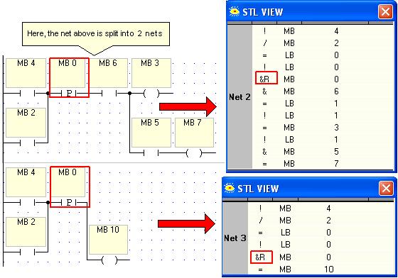
169 Ladder Example 2 159
170 U90 Ladder Software Manual Coils A coil represents a result or expression of an action. A coil can be: Memory Bit System Bit Output Timer Each contact condition is evaluated in a net to determine the coil (result or expression) condition. There are 4 types of coils: Direct Coil Inverted Coil Set Coil Reset Coil Recommended: Do not energize a coil more than once in a program. To insert a Coil from the Ladder toolbar onto a Ladder net: 1. Click once to select the desired coil. 2. Move your mouse to the desired net position. 3. Click again. There is no need to click and hold after selecting a coil. Note that, while the Direct, Set and Reset Coils are available on every menu, the Inverted Coil is not. Direct Coil A Direct Coil represents a direct result instruction of the conditions (contacts and/or function blocks) on the Ladder net before the Direct Coil. A Direct Coil instruction can be: Output Memory Bit System Bit Timer The coil result can go to an external output device (for example: a light) or an internal system element (for example: SB 2 Power Up Bit). A door buzzer contains an example of a Direct Coil. When the door buzzer button (Direct Contact) is pushed the door buzzer (Direct Coil) sounds. When you release the buzzer the sound stops. During the system scan, the processor evaluates all of the program elements on the Ladder net before the Direct Coil for power flow continuity. If no power flow continuity exists in the net (the door buzzer button is not pushed): the Direct Coil address instruction is OFF (logic 0). The door buzzer does not sound. If power flow continuity exists in the net (the door buzzer button is pressed): the Direct Coil address instruction is ON (logic 1). The door buzzer sounds. 160
171 Ladder Inverted Coil An Inverted Coil represents the opposite result instruction of the conditions (contacts and/or function blocks) on the Ladder net before the Inverted Coil. An Inverted Coil instruction can be: Output Memory Bit System Bit The result instruction can be to an external output device (for example: alarm bell) or to an internal system element (for example: SB 80 activate linearization). During the system scan, the processor evaluates all of the program elements on the Ladder net before the Inverted Coil for power flow continuity. If no power flow continuity exists in the net: the Inverted Coil address instruction is ON (logic 1). If power flow continuity exists in the net: the Inverted Coil address is OFF (logic 0). Set Coil A set coil separates the coil from the action or condition that energized the coil. Once energized, a set coil's result is no longer dependant on the action that energized it. A set coil stays energized (latched) until its condition is reset (unlatched) by a reset coil. A set coil can be: Memory Bit System Bit Output An example of a set coil is an overhead light. When we turn on a light it stays lit until we turn it off (reset or unlatch it) or the light bulb burns out. Luckily, you do not have to hold the light switch to keep the light on. An example of a coil that you do not want to be set (latched) is a car horn. You expect it to toot only when you press on the horn button and you expect it to stop when you stop pressing on the horn button. Use set and reset coils to preserve a condition in a program. Reset Coil A reset coil turns off (unlatches) a set coil, provided that there is logic continuity to the reset coil. Once a set coil is energized it stays energized, independent of the original set condition, until a reset coil with the same address resets (unlatches) the coil condition. A reset coil can be: Memory Bit System Bit Output Do not use a set coil without a reset coil in a program. Operands An element's Operand is the form in which information is stored and operated on in the U90 Ladder program. Operand lists are organized in categories, according to operand type: 161
 Timer:T (0-63) Every Operand has an Address and a Symbol. Symbols appear together with the operand every time the operand and address are used in the program.")
172 U90 Ladder Software Manual Input: I (according to model and expansion) Output: O (according to model and expansion) Memory Bit: MB (0-255) Memory Integer: MI (0-255) System Bit: SB (0-255) System Integer: SI (0-255) Timer:T (0-63) Every Operand has an Address and a Symbol. Symbols appear together with the operand every time the operand and address are used in the program. There are two types of symbols: preset and user-created. Preset symbols are descriptions that are connected to System Bits and System Integers. User-created symbols are descriptions that are written by the user for a specific project application. The user assigns a particular description to a particular operand. Power-up You can assign Power Up values to most Data Types. These values are written into the operand by the program when the controller is turned on. Outputs, MBs, SBs can be set or reset; integer values can be written into MIs and SIs. You can assign Power Up values when you place an element into a net, or by opening a Data Type list as shown below. Note If an operand has been assigned a Power-up value, it is a referenced operand and will not appear in the Unreferenced Operand list. Watch Folders Watch Folders enable you to: 162


173 Ladder Arrange related groups of operands in folders. Name the folders. View these operands in the Output Window at the bottom of the screen. To view a Watch folder, click it in the Program Navigation window. Edit the folder by right-clicking a line, then selecting the appropriate function. To add a single operand to a Watch folder, right-click it in the Ladder or in the Operand Output Window. Operand Addressing An Operand Address is the physical location in the PLC memory where the element information is stored. For example: MB 10 - "10" is the address of the MB Operand MI 35 - "35" is the address of the MI Operand T 12 - "12" is the address of the Timer Operand U90 Ladder allows you to create your own symbols before you write your program. This feature can help you to organize your project properly from the very beginning. You can also create symbols as you write your program. Symbols can be edited after you create them. Note that there is a default address setting for each operand type. The Default message box will appear if you do not specify an address: 163


174 U90 Ladder Software Manual Inputs (I) Inputs are one Operand type available for writing a project application. The number of Inputs varies according to the PLC model and any I/O Expansion Modules that may be integrated into the project. An Input is an actual hardwired input connection into the controller. Click on the Inputs folder in the Program Navigation pane to display the complete list of Inputs. Scroll down to view the complete list 164
175 Ladder Outputs (O) Outputs are one Operand type available for writing a project application. The number of Outputs varies according to the PLC model and any I/O Expansion Module integrated into the project. An Output is an actual hardwired output connection from the controller. Click on the Outputs folder in the Program Navigation pane to display the complete list of Outputs. Scroll down to view the complete list 165
176 U90 Ladder Software Manual Timers (T) U90 Ladder offers 64 On Delay Timers. Timers have a preset value, a current value, and a bit value. Timers always count down from the Preset Value. The timer value is 14 bits. Click on the Timers folder in the Program Navigation pane to display the complete list of Timers. Scroll down to view the complete list. To place a Timer in your program, place a direct coil in a net, and select T. Timer resolutions 10mS (0.01S)(from 00:00:00.01 to 00:02:43.83 ) 100mS (0.1S)(from 00:00:00.10 to 00:27:18.30) 1000mS (1.0S)(from 00:00:01.00 to 04:33:03.00 ) 10000mS (10.0S)(from 00:00:10.00 to 45:30:30.00) The first 14 bits (from the LSB) of the Timer register contains the value. The two most significant bits contain the Timer resolution. 166

177 Ladder Note that: A Timer value can be displayed in a Display as a current or elapsed value/ The Resolution field is Read-only. The resolution is a function of the Timer Preset Value. You cannot change the resolution of a timer when the application is running. A timer's current value can be changed at any time, including when the timer is active. The new value can be either greater or smaller than the previous value; storing 0 into a timer's current value stops it immediately. A change of Timer Preset value without changing the resolution will take effect when the timer restarts. Changing the resolution of the timer's preset value does not affect the current resolution; it is therefore recommended that the resolution not be changed while the timer is active. During Stop mode, timers continue to run. Memory Bits (MB) Memory Bits are one Operand type available for writing a project application. There are 256 MBs (Address MB 0 - MB 255). Memory Bits hold a bit value ( 0 or 1). Click on the Memory Bits folder in the Program Navigation pane to display the complete list of Memory Bits. Scroll down to view the complete list Memory Integers (MI) Memory Integers are one Operand type available for writing a project application. There are 256 MIs (Address MI 0 - MI 255). Memory Integers hold an integer value ( to ). Click on the Memory Integers folder in the Program Navigation pane to display the complete list of Memory Integers. Scroll down to view the complete list 167
178 U90 Ladder Software Manual System Bits System Bits are the Operating System interface to the user writing the application. System Bits are reserved by the Operating System for particular functions. Some System Bits, for example, are connected to the PLC's keypad keys. There are 256 SBs (Address SB 0 - SB 255). Only certain SBs may be written into by the programmer: SB 80: Activate Linearization SB 200 -SB 215: M90 Network Operand Click on the System Bits folder in the Program Navigation pane to display the complete list of System Bits. Scroll down to view the complete list 168
.")
179 Ladder System Integers (SI) System Integers are the Operating System interface to the user writing the application. System Integers are reserved by the Operating System for particular functions. Specific System Integers, for example, are connected to the M90's high speed counter/shaft-encoder. There are 256 SIs (Address SI 0 - SI 255). Only certain SIs may be written into by the programmer: SI 2: Current HMI Display SI 80 - SI 84: Linearization Parameters SI 200, SI 201: M90 Network Operand Click on the System Integers folder in the Program Navigation pane to display the complete list of System Integers. Scroll down to view the complete list 169


180 U90 Ladder Software Manual Assigning an Operand Address by Symbol 1. After placing the element on the net, the Select Operand and Address dialog box opens. 2. Click on the Symbol drop-down menu. 170


181 Ladder 3. Select the desired Address. 4. The element appears with the selected Address and Symbol. Changing an Operand type To change an Operand type: 1. Double click on the element's Operand. 2. The Operand and Address dialog box opens. 3. Select the new Operand type. 171


182 U90 Ladder Software Manual 4. Enter the new Operand Address and symbol. 5. Click OK. The element appears on the net with the new Operand, Address and symbol. Operand Locations List To get a list of Operand locations: If you already have one location where you know the Operand exists, you can select the Operand and then open the Find dialog box. A list of all locations of the selected Operand will appear. 1. Click on the Find icon in the Standard toolbar. 2. The Find function opens. 3. Select the name and address of the operand you wish to find. 4. Click the Find button shown below; a list appears showing every time that operand is used in the project. 5. Select the name and address of the operand you wish to replace as shown below. 172

183 Ladder 6. Select the location of the operand or description you wish to replace by clicking it within the list. 7. Replace operands or their descriptions by clicking the buttons shown below. arch Finding an Operand by symbol To find an Operand by its symbol when placing an element on a net: 1. Click in the Symbol Search box in the Select Operand and Address dialog box. 2. The Symbol Search dialog box opens. 173


184 U90 Ladder Software Manual 3. Begin entering the Symbol name for which you are searching. The list will become more specific the more letters you enter. 4. Select the desired Operand from the Symbol Search list. 174


185 Ladder 5. Click OK. The selected element appears on the net with the desired Operand and Address. Restoring System Symbols To restore System Symbol values: Keep in mind that there are SBs and SIs reserved for use by the system, such as SB 4 Divide by Zero or SI 4 Divide Remainder. Those SBs and SIs cannot be written into. If you accidentally write into them, you can recover their symbols. Note that SBs and SIs are for system use. Even those currently 'blank' may be assigned a function in a later controller model. Writing into System Bits and System Integers is solely at the discretion of the programmer and the programmer is solely responsible for any problems that may arise as a result. 175


186 U90 Ladder Software Manual Operands in use To check what Operands are being used in a project: 1. Open the Window Menu on the Main menu bar. 2. Select the Operand type you wish to check. 3. The Operand List window opens. The Operands in use are marked with a check mark in the In Use box. 176


187 Ladder Deleted Unreferenced Operands To help manage your project, you can delete unreferenced operands. The utility searches through the entire application, including Hardware Configuration, SMS, and PID. Note If an operand has been assigned a Power-up value, it is a referenced operand and will not appear in this list. 177

188 U90 Ladder Software Manual Operand Values: The integer value range is 2 16_ 1: that is to Keep this integer range in mind when creating function blocks. For example: MI 75 + #50 = MI 76 If MI 75 goes beyond 32626, the integer value returned in MI 76 will be a negative number! Functions Functions The following types of Function Blocks can be used in your program: Compare Functions Logic Functions Math Functions Store functions Clock Functions Loops: Jump to Label Special Functions: without Ladder elements VisiLogic contains special functions that are not represented by Ladder Elements. You can perform these functions by storing values into the System Integers listed here. To see a list of functions, check the Special Functions list. 178
189 Ladder Compare Functions A compare function represents a data manipulation instruction. U90 Ladder uses function blocks to operate compare functions. Each function block takes 2 inputs (MI, SI or a constant integer) and manipulates them according to the function block instruction. If the function block instructions are true (logic 1): power flows through the block. If the function block instructions are false (logic 0): power does not flow through the block. There are 6 types of Compare Functions: Greater Than Greater Than or Equal To Equal To Not Equal To Less Than or Equal To Less Than Equal The Equal function block evaluates input A to see if its constant integer value is equal to input B. If input A is equal to input B: power will flow through the function block. If input A is not equal to input B: power will not flow through the function block. Input Operands A & B must be integer values: MI, SI or # constant integer value. According to the above example: If MI 1 is equal to MI 3; then MB 55 will go to logic "1" (ON). If MI 1 is not equal to MI 3; then MB 55 will go to logic "0" (OFF). Greater or Equal The Greater Than or Equal function block evaluates input A to see if its integer value is greater than or equal to input B. If input A is greater than or equal to input B: power will flow through the function block. If input A is not greater than or not equal to input B: power will not flow through the function block. 179
190 U90 Ladder Software Manual According to the above example: If MI 1 value is greater or equal to constant integer 35; then MB 50 will go to logic "1" (ON). If MI 1 value is not greater or equal to constant integer 35; then MB 50 will go to logic "0" (OFF). Greater Than The Greater Than function block evaluates input A to see if its current value is greater than input B. If input A is greater than input B: power will flow through the function block. If input A is not greater than input B: power will not flow through the function block. According to the above example: If MI 1 value is greater than 35; then MB 50 will go to logic "1" (ON). If MI 1 not greater than 35; MB 50 will go to logic "0". Care must be taken when using greater and less than function blocks. Do not create a program with instructions for Greater Than and Less Than but without an instruction block for how to proceed in a situation where input A equals input B. Less or Equal The Less Than or Equal To function block evaluates input A to see if its current value is less than or equal to input B. If input A is less than or equal to input B: power will flow through the function block. If input A is not less than or equal to input B: power will not flow through the function block. 180
191 Ladder According to the above example: If MI 1 value is greater than the MI 3 value; then MB 51 will go to logic "1" (ON). If MI 1 not greater than the MI 3 value; MB 51 will go to logic "0". Less Than The Less Than function block evaluates input A to see if its integer value is less than input B. If input A is less than input B: power will flow through the function block. If input A is not less than input B: power will not flow through the function block. According to the above example: If MI 1 value is less than constant integer 35; then MB 60 will go to logic "1" (ON). If MI 1 value is not less than constant integer 35; MB 60 will go to logic "0" (OFF). Not Equal The Not Equal function block evaluates input A to see if its integer value is not equal to input B. If input A is not equal to input B: power will flow through the function block. If input A is equal to input B: power will not flow through the function block. Input Operands A & B must be integer values: MI, SI or # constant integer value. 181

192 U90 Ladder Software Manual According to the above example: If MI 1 is not equal to MI 3; then MB 65 will go to logic "1" (ON). If MI 1 is equal to MI 3; then MB 65 will go to logic "0" (OFF). Using the Compare function To use the Compare function: 1. Click Compare on the Standard toolbar. The Compare function list opens. 2. Select the desired Compare function. 3. Move the function block that appears to the desired net location. 4. Click to place the function block. The Select Operand and Address dialog box opens. 182


193 Ladder 5. Enter the Operands and Addresses in the dialog boxes and click OK. 6. The Compare function block appears with the selected Operands and Addresses. Logic Functions You perform logical functions in U90 Ladder by using logic function blocks. Function blocks are provided for: AND OR XOR The internal operation of a function block is transparent to the user. You input the two operands. The result is automatically output by the function block Input Operands A & B must be integer values: MI, SI or # constant integer value. 183
 in both input A and B then the output C will be true (logic 1). If input A and B is false (logic 0) - the output C will be false (logic 0).")

194 U90 Ladder Software Manual Output Operand C may be a Memory Integer or a System Integer. AND Example The AND logic function block can evaluate the state of two integers. If a bit is true (logic 1) in both input A and B then the output C will be true (logic 1). If input A and B is false (logic 0) - the output C will be false (logic 0). If either input A or B is false (logic 0) - the output C will be false (logic 0). Input Operands A & B must be integer values: MI, SI or # constant integer value. Output Operand C may be an MI or a SI. AND can be used to mask out certain bits of an input integer not relevant to a given function. Example: If a clock function block uses the first bit of a 16-bit word to decide if a given time is A.M. or P.M., you can mask out the other 15 bits. This will tell you if the current time is A.M. or P.M. All of the non-relevant bits will be turned off (logic 0) expect the A.M. / P.M. bit. 184
195 Ladder AND Example You want to determine if an MI / SI value is an odd or an even number in your application. An AND function between an integer A and #1: If integer A is an even number then the result of the AND operation = #1. If integer A is an odd number then the result of the AND operation = #0 OR The OR logic function block can evaluate the state of two integers to see if either input A or B is true. If input A OR B is true - the output C will be true (logic 1). If both input A and B are true (logic 1) - the output C will also be true (logic 1). Input Operands A & B must be integer values: MI, SI or # constant integer value. Output Operand C may be a Memory Integer or a System Integer. 185
. If both input A and B are true (logic 1) - the output C will be false (logic 0).")

196 U90 Ladder Software Manual XOR The XOR logic function block can evaluate the state of two integers to see if input A and B are equal. If either input A OR B is true - the output C will be true (logic 1). If both input A and B are true (logic 1) - the output C will be false (logic 0). If both input A and B are false (logic 0) - the output C will be false (logic 0). Input Operands A & B must be integer values: MI, SI or # constant integer value. Output Operand C may be a Memory Integer or a System Integer. Use XOR to recognize changes in an integer to check for integer bit corruption. If 2 integers are equal: the result will return logic 0. If there has been bit corruption: the corrupted bit will return logic


197 Ladder Loops Loops: Jump to Label Loops in a Ladder project cause the program to jump over certain net(s), according to specific logic conditions. A Loop contains a Jump element and a Label. When the Jump condition(s) is true, the project jumps to the associated Label. To create a Loop in your project: 1. Click Loop on the Ladder toolbar. 2. Select Set Label from the Loop menu. Place the cursor in the desired net and click. 3. The Edit Label box opens. 187

198 U90 Ladder Software Manual 4. Enter a Label name of up to eight characters. 5. The Label appears above the net. 6. Select Jump from the Loop menu. 7. Place the Jump in the desired place on the desired net Select Jump to... window appears.


199 Ladder 9. Select the desired Label name to which you want to jump. Click OK. 10. The Jump element appears with the selected Label name on the net. According to the above example, if Ladder logic is true for net 4, the program will jump over nets 5 and 6 and continue from net 7. Important note: You must take care when creating Loops not to create an endless Loop. While you can place Labels before a Jump condition and you can refer to a Label more than once, repeated referrals to a Label above a Jump element can create an endless loop which will cause the controller to stop with an error message "PROGRAM LOOP." Loop functions are featured in the sample application, such as the applications ' Shortening scan time-jump'. This application may be found by selecting Sample U90 Projects from the Help Menu. 189
200 U90 Ladder Software Manual Math Functions Math Functions You perform mathematical functions in U90 Ladder by using math function blocks. Function blocks are provided for: Addition Subtraction Multiplication Division The internal operation of a function block is transparent to the user. You simply input the two operands. The result is automatically output by the function block. The example below shows the Add function block. Input Operands A & B must be integer values: MI, SI or # constant integer value. Output Operand C may be a Memory Integer or a System Integer. You can use an Add function block to assign a real number value to an MI or SI. Add 190
201 Ladder Example The math function add is executed by the Add function block shown below. Input Operands A & B must be integer values: MI, SI or #constant integer value. Output Operand C may be a Memory Integer or a System Integer. Add Examples You can use the Add function to add an MI value to an integer value. You can use the Add function to add two MI values. You can use the Add function to add two integer values. 191
202 U90 Ladder Software Manual You can use Add function blocks in series. Divide Examples The math function divide is executed by the Divide function block shown below. 192 Input Operands A & B must be integer values: MI, SI or #constant integer value. Output Operand C may be a Memory Integer or a System Integer. The Divide function can only return whole numbers. This function does not support floating point integers. Examples: 7.2 and 9.5. Use System Integer 4 (SI 4 - Divide Remainder) to find the exact integer value of a division function that may involve a remainder. Note that you must use the remainder value in SI 4 immediately after the division function. SI 4 will be written over with the next division function and the specific remainder value will be lost. System Bit 4 (SB 4 - Divide by Zero) will activate if the division operation will inadvertently result in a division by zero and return zero in Operand C.
203 Ladder Division Examples Remember that any remainder of a Division function will be written into SI 4. You must use any remainder value immediately after the Division function because SI 4 will be written over with the next division function and the specific remainder value will be lost. SB 4 (Divide by Zero) will activate if the division operation will inadvertently result in a division by zero and it will return zero in Operand C. You can use the Division function to divide an MI value and integer value. You can use the Division function to divide two MI values. You can use the Division function to divide two integer values. You can use Math function blocks in series. 193


204 U90 Ladder Software Manual Division Function: Remainder values To get the remainder value of a Division function: 1. Enter the desired Operands into the Division function block. 2. Select System Integers from the Window Menu on the Standard Menu bar. 3. SI 4 holds the Remainder value for the most recent Division operation. 194

205 Ladder According to the above example: If MI 10 = 7 and MI 11 = 2, then MI 12 = 3 and SI 4 = 1 Multiply Examples The math function Multiply is executed by the Multiply function block shown below. Input Operands A & B must be integer values: MI, SI or #. Output Operand C may be a Memory Integer or a System Integer. Multiplication Examples You can use the Multiplication function to multiply an MI with an integer value. You can use the Multiplication function to multiply two MI values. 195
206 U90 Ladder Software Manual You can use the Multiplication function to multiply two integer values. You can use Multiplication function blocks in series. Subtract Examples The math function subtract is executed by the Sub function block shown below. 196

207 Ladder Input Operands A & B must be integer values: MI, SI or # constant integer value. Output Operand C may be a Memory Integer or a System Integer. Subtraction Examples You can use the Subtraction function to subtract between an MI value and an integer value. You can use the Subtraction function to subtract between two MI values. You can use the Subtraction function to subtract between two integer values. You can use Subtraction function blocks in series. 197
. From the Select Operand and Address dialog box select # for the Operand type and Address.")

208 U90 Ladder Software Manual Math functions: Constant integers, MI,or SI To execute a math function between an integer and MI/SI: Each Math function has 3 elements: 2 input values and 1 output value. Each of these 3 elements has the possibility of being an integer (as well as a MI or SI). From the Select Operand and Address dialog box select # for the Operand type and Address. Enter the integer (number) value in the Symbol box. Store Functions An MI Operand contains an integer value ( to ). There are two ways to store an integer value in an MI: Store Direct Store Indirect The last integer value written into a specific MI will overwrite any previous integer value stored there before. Example: MI 6 = 35. You then write the value 37 into MI 6, the value 35 will be replaced by the value 37. Store functions are featured in several sample applications, such as the application ' History of Events'. These applications may be found by selecting Sample U90 Projects from the Help Menu. 198


209 Ladder Store Direct function Store Direct allows you to write a constant, MI or SI value into another MI or SI. To use the Store Direct function: 1. Click Store on the Ladder Toolbar. 2. Select Store Direct from the Store Menu. 3. Move the Store Direct element to the desired net. 4. Enter the desired Operands and Addresses. 5. The Store Direct element appears on the net with the set Operands and Addresses. 199
210 U90 Ladder Software Manual According to the above example, the value in MI 3 will be stored in MI 100. The previous value in MI 100 is lost. The current value in MI 3 remains unchanged. Store Indirect function Store Indirect allows you to write an integer value (constant, MI or SI ) into another MI or SI using indirect addressing. For example: When using the Store Indirect MI, if the value stored in the B parameter is 5; then MI 5 is the address where the value will be stored. When using the Store Indirect SI, if the value stored in the B parameter is 2; then SI 2 is the address where the value will be stored. For example: According to the above example: If MI 30 contains the constant 5; then #27 will be stored in MI 5. If MI 30 contains the constant 35; then #27 will be stored in MI 35. There are two types of Store Indirect function: The Store Indirect MI function relates to the MI address. The Store Indirect SI function relates to the SI address. To use the Store Indirect function: 1. Click Store on the Ladder Toolbar Select Store Indirect MI on the Store menu.


211 Ladder 3. Enter the desired Operands, Addresses and Symbols. Click OK. 4. The Store Indirect MI element appears on the net. Time Functions Clock Functions You perform clock and calendar functions in the U90 Ladder with Clock function blocks. These functions are on the Clock drop-down menu of the Ladder toolbar: Time Day of the Week Day of the Month Month Year U90 Ladder provides 2 methods for executing Clock functions: Direct Indirect You set the value of Direct Clock functions when you write your project. The user sets the value of an Indirect Clock function from the PLC via the keypad. 201
212 U90 Ladder Software Manual To learn how to use Clock functions, check sample applications, such as the applications ' School Bell Direct', 'Database Log', and 'Print & Time'. To open these applications, select Sample U90 Projects from the Help Menu. Time of Day The Time function block is used for 24 hour time functions. Direct Time Function: The Direct Time function block has a 'from' (start) and a 'to' (end) time set by the programmer. If the RTC is between these two times: power will flow through the function block. If the RTC is not currently between these two times: power will not flow through the function block. According to the above example: Between 13:30 and 21:45 the function block will go to logic "1" (ON). From 21:46 to13:29 the function block will go to logic "0" (OFF). Indirect Time Function: The Indirect Time function block is linked to two consecutive MIs or SIs. These integer values are entered by the user via the keypad. If the RTC is between these two times: power will flow through the function block. If the RTC is not currently between these two times: power will not flow through the function block. You must create a Time Function Variable in Hour (CT) format for the user to enter the start and end times. Direct Clock function The Direct Clock function allows the programmer to write a Ladder program using calendar conditions for: Time of Day Day of the Week Day of the Month Month Year These functions are located on the Clock drop-down menu of the Ladder toolbar. 202

 to activate a task.")

213 Ladder You set the value of Direct Clock functions when you write your project. You must use the Indirect Clock functions if you want the user to set the value of a Clock function via the PLC's keypad. Day of the Week The Day of the Week function block is used for weekday functions, e.g. Monday, Tuesday. Direct Day of the Week: The programmer uses this function to select on which day(s) to activate a task. If the RTC coincides with a selected day of the week: power will flow through the function block. If the RTC does not coincide with a selected day of the week: power will not flow through the function block. To link a Direct Clock function: 1. Click Clock on the Ladder toolbar. 2. The Clock drop-down menu opens. 3. Select Direct Clock Functions. 4. Select Day Of The Week from the Direct Clock Functions menu. 5. Move the Day of the Week element to the desired net. 203
 only when MB 6 = 1 and on Monday or Tuesday.")
214 U90 Ladder Software Manual 6. Select the desired days from the Day Of The Week window and click OK. 7. The selected days appear in blue highlights in the element on the net. According to the above example, the net result will be true (logic 1) only when MB 6 = 1 and on Monday or Tuesday. Indirect Day of the Week: The Indirect Day of the Week function comprises: Indirect Day of the Week function block Time Function Variable in the Day of the Week format (CW) Display for entering values The Indirect Day of the Week function values are entered by the user via the 204
215 Ladder Up and Down scroll arrow keys for scrolling through the days of the week +/- keys for selecting the desired days of the week Enter key for confirming selection The Indirect Day of the Week values are entered into a 7-bit bitmap in the linked MI. According to the above example: On Monday, Wednesday and Friday the function block will go to logic "1" (ON). On Sunday, Tuesday, Thursday and Saturday the function block will go to logic "0" (OFF). Day of the Month The Day of the Month function block is used for date functions, e.g. 14th and 21st of a month. Direct Day of the Month: The Direct Day of the Month function block has thirty-one boxes for the thirty-one possible days of a month. If the RTC coincides with a selected day of the month: power will flow through the function block. If the RTC does not coincide with a selected day of the month: power will not flow through the function block. According to the above example: On the 7th, 14th, 21st and 28th the function block's output will be to logic "1" (ON). On the other days of the month the function block's output will be logic "0" (OFF). Indirect Day of the Month: The Indirect Day of the Month function comprises: Indirect Day of the Month function block Time Function Variable in Day of the Month format (CD) Display for entering values The Indirect Day of the Month function values are entered by the user utilizing 205

216 U90 Ladder Software Manual Up and Down scroll arrow keys for scrolling through the days of the month +/- keys for selecting the desired days of the month Enter key for confirming selection The Indirect Day of the Month function values are entered into two MIs to create 31-bit bitmap in the linked MIs. According to the above example: On the 12th, 14th, 19th, 21st and 28th of the month the function block's output will be logic "1" (ON). On the other days of the month the function block's output will be to logic "0" (OFF). Year The Year function block is used for yearly time functions. Direct Year Function: The Direct Year function block has a 'from' (start) and a 'to' (end) year set by the programmer. If the RTC is within these two years: power will flow through the function block. If the RTC is not currently within these two years: power will not flow through the function block. According to the above example: Between the years the function block will go to logic "1" (ON). With the year 2036 the function block will go to logic "0" (OFF). Indirect Year Function: The Indirect Year function block is linked to two consecutive MIs or SIs. These integer values are entered by the user via the keypad. If the RTC is within these two times: power will flow through the function block. 206
 format for the user to enter the start and end years.")

217 Ladder If the RTC is not currently within these two times: power will not flow through the function block. You must create a Time Function Variable in Year (CY) format for the user to enter the start and end years. Direct Clock function example You want to create a project where a machine is working in January and March beginning on the 12th day of a month, until and including the 20th in the years 2000 and 2001 between the hours 10:30 and 12: Click Clock on the Ladder toolbar. 2. Select Direct Clock Functions. The Direct Clock Functions menu opens. 3. Select Day of the Month and place it in the desired place on the net. 207


218 U90 Ladder Software Manual 4. The Day of the Month menu opens. 5. Click the desired days of the month. 6. The Days of the Month function appears on the net with the selected days of the week highlighted. 7. Select the Year function. The Year menu opens. 8. Enter the desired Year range. 208


219 Ladder 9. The Year function appears with the desired values. 10. Select Month on the Direct Clock Functions menu. 10. The Month menu opens. 11. Select the desired Months. Click OK. 12. The Month of the Year function appears with the desired Months highlighted. 13. Select Time from the Direct Clock Functions menu. 209


220 U90 Ladder Software Manual 14. Enter the desired Time range in the Hour menu. Click OK. 15. Expand the net rung as needed in the net using the Line Draw tool. 16. Select and place a Direct Coil on the net. Enter the desired Operand, Address and Symbol. 210
221 Ladder 17. The net appears as shown below. Indirect Clock function Indirect Clock functions allows the programmer to write a Ladder program where the user will enter the time value via the keypad. Functions are provided for: Indirect Time of Day Indirect Day of Week Indirect Day of Month Indirect Month Indirect Year These functions are located on the Clock drop-down menu of the Ladder toolbar. Indirect Day of Week function This example shows you how to create a project where a machine works according to a time that the user enters via the keypad. 1. Select Indirect Clock Functions from the Clock menu of the Ladder toolbar. 2. Select Day Of The Week from the Indirect Clock Function menu. 211
222 U90 Ladder Software Manual 3. Place the Day Of The Week function on the desired net. Enter the desired Operand, Address and Symbol. 4. The Day Of The Week function appears with the selected Operand, Address and Symbol on the net. 5. To enable the user to view and modify the Indirect Clock function values, you must now create HMI Displays and Variables. Click Variables on the Standard toolbar The Variable Editor opens. Select Time Functions for each Variable. Link the Variable to the appropriate MI. Select the appropriate Variable Information Format for the time. Below is the Start Time Variable for the time in hours.
223 Ladder 7. The Day of the Week Variable. When you download the application to the controller, the user will use the Up/Down arrow keys to scroll through the days of the week. When the display shows the correct day, the user selects it by pressing the Enter key. Note that in M90/91 controllers the Up key is numeric key 3, and the Down key is numeric key


224 U90 Ladder Software Manual Indirect Clock function example This example shows you how to create a project where a machine is working according to a time and date entered by the user via the keypad. 1. Select Indirect Clock Functions from the Clock menu of the Ladder toolbar. 2. Select Time from the Indirect Clock Functions menu. 3. Enter the desired Operand, Address and Symbol. 4. The Hour function appears with the selected Operand and Address. Note that the hour function is checking a range between two MIs / SIs. Therefore, two Operands are needed: the beginning and the end of the range. The program automatically takes the next Operand from the one you enter. According to the following example, you enter MI 1 and the program assigns the end of the range to MI 2, the next MI. 214


225 Ladder 5. Select Day Of The Week from the Indirect Clock Function menu. 6. Place the Day Of The Week function on the desired net. Enter the desired Operand, Address and Symbol. 7. The Day Of The Week function appears with the selected Operand, Address and Symbol on the net. 215
226 U90 Ladder Software Manual 8. Select Day of the Month from the Indirect Clock Function menu. 9. Enter the desired Operand, Address and Symbol. The Day of the Month function is a 32 - bit Bit map. Therefore it requires two MIs / SIs. The program automatically takes the next Operand from the one you enter. According to the following example, you enter MI 4 and the program assigns the end of the range to MI 5, the next MI. 10. Select Month from the Indirect Clock Functions menu. 216


227 Ladder 11. Enter the desired Operand, Address and Symbol. 12. Place a Direct Coil at the end of the rung. Enter the desired Operand, Address and Symbol. 13. The net appears as shown in the next figure. 217
228 U90 Ladder Software Manual 14. To enable the user to view and modify the Indirect Clock function values, you must now create HMI Displays and Variables. Click Variables on the Standard toolbar. 15. The Variable Editor opens. Select Time Functions for each Variable. Link the Variable to the appropriate MI. Select the appropriate Variable Information Format for the time. Below is the Start Time Variable for the time in hours. 16. The End Time Variable for the time in hours. 218


229 Ladder 17. The Day of the Week Variable. 18. The Day of Month Variable. 219

230 U90 Ladder Software Manual 19. The Month Variable. 20. Create the Displays for the Variables. Below is an example for viewing the time range in hours. 220

231 Ladder When you download the application to the controller, the user will use the Up/Down arrow keys to scroll through the days of the week, days of the month and month. When the display shows the correct day, the user selects it by pressing the Enter key. Note that in M90/91 controllers the Up key is numeric key 3, and the Down key is numeric key 6. Indirect Day of Month function This example shows you how to create a project where a machine works according to a time entered by the user via the keypad. 1. Select Indirect Clock Functions from the Clock menu of the Ladder toolbar. 2. Select Day of the Month from the Indirect Clock Function menu. 221
232 U90 Ladder Software Manual 3. Enter the desired Operand, Address and Symbol. The Day of the Month function is a 32 - bit Bitmap. Therefore it requires two MIs / SIs. The program automatically takes the next Operand from the one you enter. According to the following example, you enter MI 4 and the program assigns the end of the range to MI 5, the next MI. 4. To enable the user to view and modify the Indirect Clock function values, you must now create HMI Displays and Variables. Click Variables on the Standard toolbar. 5. The Variable Editor opens. Select Time Functions for each Variable. Link the Variable to the appropriate MI. Select the appropriate Variable Information Format for the time. Below is the Start Time Variable for the time in hours. 222
233 Ladder 6. The Day of Month Variable. When you download the application to the controller, the user will use the Up/Down arrow keys to scroll through the days of the month. When the display shows the correct day, the user selects it by pressing the Enter key. Note that in M90/91 controllers the Up key is numeric key 3, and the Down key is numeric key
234 U90 Ladder Software Manual Special Functions: without Elements Special Functions (Via SBs & SIs) List Click on the function name to view a Help topic containing specific instructions on how to implement the function. Special Functions: without Ladder elements U90Ladder contains special functions that are not represented by Ladder Elements. You can perform these functions by storing values into the System Integers listed here. To implement a special function: 1. Store the parameters of the function in the relevant SI function operands. 2. Store the command number into SI 140. Note that the command number must be stored into SI 140 after the parameters are stored into the operands. SI Description 140 Function Number 141 Function Operand #1 142 Function Operand #2 143 Function Operand #3 144 Function Operand #4 145 Function Operand #5 146 Function Operand #6 146 Function Operand #7 The example below shows the function A*B/C, which enables the PLC to multiply 2 operand values & divide the product by a third operand. 224
235 Ladder Function # (SI 140) Description 100 Multiply A x B, Divide by C Note that when you run Test (Debug) Mode, the current value in SI 140 will not be displayed. Functions activated by SI 140 Function Name A*B/C Description Parameters Execute Function, Store into SI140 Enables PLC to multiply 2 operand values & divide the product by a third operand. SI 141 Operand A (multiplicand). SI 142 Operand B (multiplicand), SI 143 Operand C (divisor). 100 Change COM Port Parameters Enables you to change the serial communication port default settings for M91 controllers. M90 models do not support this function. SI 141 Baudrate SI 142 Data bits SI 143= Parity e SI 144 Hardware flow control SI 145 = Timeout 10ms units SI 140: 310 SI 146 = Stop bits SB 141 indicates whether the COM port has been successfully initialized with the new parameters successfully: 1 = success, 0 =fail Communication Utility Enables PLC to receive data from external devices, such as barcode readers, via an RS232 port. SI 141 STX SI 142 ETX SI 143 ETX Length or Silent SI 144 Maximum Length 300 Additional Functions: Set SB 61 to Copy Data in Receive Buffer to Vector 225
236 U90 Ladder Software Manual SI 145 Start Address: Receive Buffer SI 60 # of Bytes currently in Receive Buffer SI 61 # of Bytes in Receive Buffer when SB 60=1 SI 146 Copy Data: Format Set SB 62 to Clear Receive Buffer, Clear SI 60, Clear SI 61,& Reset SB 60 SB 60 Data Successfully Received Copy Vector Sets a vector, copies source values, then writes those values into a corresponding target vector. SI 141 Source Vector SI 142 Vector Length SI 143 Target Vector Copy MIs to MIs: 20 Copy MIs to DBs: 21 Copy DBs to MIs: 22 Copy DB to DB: 23 Copy vector of MBs Sets an MB vector, copies source values, then writes those values into a corresponding target MB vector. SI 141 Source MB Vector SI 142 Target Vector SI 143 Vector Length 24 Fill Vector Copies a source value, then write that value into every operand within the target vector. SI 141 Start of Target vector, SI 142 Length of Target vector, SI 143 Fill Value; register whose value will be written into each register within the target vector Fill MI vector: 30 Fill DB vector: 31 Fill MB vector: 36 Set bit in MI vector Sets a bit within an MI vector SI 141 Start of MI vector, SI 142 Location of bit to be set within vector (offset) 37 Reset bit in MI vector Resets a bit within an MI vector SI 141 Start of MI vector, SI 142 Location of bit to be reset within vector (offset) 38 Test bit in MI Vector Selects a bit within a vector of registers, and stores its status in an MB. SI 141 Start of Target vector, SI 142 Location of bit to be set within vector (offset), SI 143 Target Bit, determines the address of the MB, where the value of the selected bit will be stored. 39 Find Mean, Maximum, and Minimum Values Finds within vector: Mean, Minimum, & Maximum. SI 141 Start of vector, SI 142 Length of vector Find in MI vector: 40 Find in DB vector: 41 GSM PIN Code via MI Interrupt Uses an MI vector to supply a GSM modem PIN code Causes program to stop immediately without regard to program scan SI 141 Start of vector 410 See Interrupt for details 500 Loadcell M91 PLCs support Loadcell via I/O Expansion modules IO-LCxx. Check the Loadcell topic for details and a commands list. Load Indirect 226 Takes value contained in a source operand and SI 141 Data source Load MI to MI: 10
237 Ladder loads that value into a target operand using indirect addressing SI 142 Load target Load SI to MI: 11 Load MI to SI: 12 Load SI to SI: 13 Load Timer Preset/Current Value MODBUS Load a preset or current timer value into another operand Enables MODBUS Master/Slave communications SI 141 to select the timer; 0-63 Load Timer Preset: 202 Load Timer Current: 203 See MODBUS for details Configure: 600, enable PC applications access (see MODBUS topic) Configure: 600 Read Coils: 601 Force Coil: 602 Force Coils: 603 Read Output Registers: 604 Preset Register: 605 Preset Registers:606 Read Output Registers in Float Format: 607 Preset Float Registers: 608 Read Input Registers: 609 Read Input Registers in Float Format: 610 Read Inputs: 611 Loopback Test: 612 SMS Phone Number: via MI Pointer Uses an MI vector to supply a phone number in the SMS phone book SI 141 Start address of the MI vector containing the phone number Store 400 into SI 140 Store Timer's Preset/Current Value Store a value into a timer to change the preset or current timer value. SI 141 to select the timer; 0-63, SI 142 to determine the timer value, Store Timer Preset: 200 Store Timer Current: 201 SI 143 to select the timer's resolution Square Root Finds the square root of a number SI 141 Store the number Store 110 into SI 140 Temperature Convert C to F SI 141 Data Source: C value 130 SI 142 Result: F value Degree value representation: 500 means 50.0 Temperature Convert F to C SI 141 Data Source:F value 131 SI 142 Result: C value Degree value representation: 500 means
238 U90 Ladder Software Manual Functions activated by SBs Function Name Description Parameters Activating SB-SI Convert MB to MI, MI to MB Converts 16 bits or more into a integer value, or an integer value into 16 bits SI 170 Address of MI containing integer value SI 171 Start address of MB array (vector) SI 172 Amount of MBs Set SB 170 to activate MB to MI Set SB 171 to activate MI to MB Copy MI to Output vector, Input vector to MI Copy a vector of Inputs (I) to a register. Copy a register value to a vector of Outputs (O) SI 170 Address of MI containing integer value SI 171 Start address of bit array (vector) SI 172 Amount of bits Set SB 170 to activate I to MI Set SB 171 to activate MI to O Database The M90/91 has a special memory area containing integers that are function as a database. Within the database, you can access and use integers 0 through 1023 via SI 40 and SI 41. See Using the Database for details. Delete SMS messages Delete SMS messages from a SIM card SI 187, Number of SMS messages to be deleted Set SB 193 to delete messages (default 20 messages) Immediate: Read Inputs & HSC, Set/Reset Outputs Perform immediate actions, without regard to the program scan. Model-dependent; see Immediate: Read Inputs & HSC, Set/Reset Outputs for details. Long Integer Functions Uses adjacent MIs in performing calculations and storing results. M91 Only. Set SB 82 to treat 2 registers as 'long integer' Linearization Convert analog values from I/Os into decimal or other integer values SI 80-85: (x,y) variable ranges. Set SB 80 to activate the Linearization function. Shift Register Load SI 87 with a value, use SBs to shift register bits left/right SI 87 Contains the number to be shifted SI 88 contains the number of bits to be shifted (Default is 1 bit) Set SB 87 to shift left Set SB 88 to shift right 'Long' Integer functions This special function is only supported by M91 controllers ( OS 91). Note that constant values are not supported, only MI value may be used. Long integer functions are activated via SB82. A long integer function uses adjacent MIs in performing calculations and storing results. When SB82 is used as the activating condition for a Math, Compare, or Store function, selecting a single MI as an input value causes the following MI to be included with the input. The selected MI value fills the 2 'lower bytes' of the long register, and the following MI fills the 2 'higher bytes'. The same logic holds for the output value. In the example below, the values in MI 0 and MI 1 provide the 'A' input, MI 2 and MI 3 provide the 'B' input. Note that MI 0 provides the value that fills the 2 'lower bytes', and MI 1 provides the value that fills the 2 'higher bytes' of the long integer. 228


239 Ladder The result is stored in MI 10 (low) and 11 (high). In the Compare function below, MI 10 contains 100, MI 11 contains 3, MI 12 contains 100, and MI13 contains 0, making the comparison true. Note that to activate Compare functions, SB 82 must be on the left ladder rail. This is not so for Math and Store functions. You can use the Store function in two ways; these can enable you to display long values on the LCD. Note that in order to display long values, the variable used to represent the 'low' byte should be configured to show leading zeros. Display is restricted to positive values within the range of 0-99,999,999. Setting SB82 before a Store function causes the 'A' value to be treated as a 32-bit 'long' value; the long value is then broken up into the 2 16-bit MIs constituting the 'B' value. Resetting SB82 before a Store function causes the 'A' value to be treated as a 2 16-bit values; the values are then stored as a long 32-bit 'B' value. 229

240 U90 Ladder Software Manual Deleting SMS messages In order to delete SMS messages from a SIM card, turn SB 193, Delete SMS Messages, ON. When used alone, SB 193 will delete 20 messages from the SIM card. Using SB 193 in conjunction with SI 187, Number of SMS messages to be deleted, enables you to delete up to 30 SMS messages. GSM PIN Code via MI Use this utility to use an MI vector to supply a GSM modem PIN code. When you use this function, the controller will look for the number in the MIs, bypassing the PIN code in the SMS message dialog box. Note that since there is no Ladder element for this function; you perform it by: Storing the start address of the MI vector needed to contain the PIN into SI 141, Storing 410 into SI 140 to select the function. Storing the function number calls the function. In your application, call the function after you have entered all of the other parameters. Note that when you run Test (Debug) Mode, the current value in SI 140 will not be displayed. The PIN code should be called before the modem is initialized; the function should therefore be called as a power-up task. Note that if the MIs contain an incorrect PIN code format, the error will be indicated by Error message #18 in SI 180--Illegal PIN Format. 230
241 Ladder Linearization Linearization can be used to convert analog values from I/Os into decimal or other integer values. An analog value from a temperature probe, for example can be converted to degrees Celsius and displayed on the controller's display screen. Linearize values for Display Note that the linearized value created in this way may be displayed-- but the value cannot be used anywhere else within the project for further calculations or operations. You can enter an Analog value, such as temperature, via the keypad, then convert that value into a Digital value for comparison with a digital value from a temperature probe by selecting Enable Linearization in the linked Variable. This conversion process is Reverse Linearization. To enable Analog to Digital conversion: 1. Create a Display for entering the analog value. 2. Create an Integer Variable. 3. Select keypad entry and enable linearization. 4. Enter the linearization values for the x and y axes.. 231
242 U90 Ladder Software Manual According to the above example: A temperature entry of C will be converted to 1023 Digital value. A temperature entry of 50 0 C will be converted to 512 Digital value. Linearize values in the Ladder You can also linearize values in your Ladder and display them on the LCD. 1. In your Ladder project, use SI to set the (x,y) variable ranges. Use SB 80 to activate the Linearization function. The linearization values created here can be displayed by linking SI 85 to a Display;the value can be used elsewhere within the project for further calculations or operations. 232
243 Ladder Example: write the variable ranges into SI 80-83, then writing an analog input into SI 84: Load Indirect Load Indirect allows you to take a value contained in a source operand and load that value into a target operand using indirect addressing. Note that since there is no Ladder element for this function; you perform it by storing values into: 233

 Offset in Vector, Source (SI 141) Offset in Vector, Target (SI 142) 10 MI MI 11 SI MI")
244 U90 Ladder Software Manual SI 141 to determine the data source, SI 142 to determine the load target, SI 140 to select the type of function. Storing the function number calls the function. In your application, call the function after you have entered all of the other parameters. To use Load Indirect: Function # (SI 140) Offset in Vector, Source (SI 141) Offset in Vector, Target (SI 142) 10 MI MI 11 SI MI 12 MI S 13 SI S Note that when you run Test (Debug) Mode, the current value in SI 140 will not be displayed. 234
. You can copy from/to a vector of MI registers or Database registers by selecting the appropriate function.")
245 Ladder Copy Vector Vector Copy enables you to set a range of operands, copy the values of each operand within that range (source), then write those values into a corresponding range of operands of the same length (target). You can copy from/to a vector of MI registers or Database registers by selecting the appropriate function. Note that since there is no Ladder element for this function; you perform it by storing values into: SI 141 to determine the source vector, SI 142 to determine the length of the vector, SI 143 to determine the target vector, SI 140 to select the type of function. Storing the function number calls the function. In your application, call the function after you have entered all of the other parameters. To use Copy Vector: Function # (SI 140) Source Vector, (SI 141) Target Vector, (SI 142) 20 MI MI 21 MI DB 22 DB MI 23 DB DB Note that when you run Test (Debug) Mode, the current value in SI 140 will not be displayed. 235
, then writes that value into every operand within the range (target vector).")
246 U90 Ladder Software Manual Fill Vector Fill Vector enables you to set a range of registers. The function copies a value from a desired operand or constant value (source), then writes that value into every operand within the range (target vector). You can fill a vector of MI registers or Database registers by selecting the appropriate function. Note that since there is no Ladder element for this function; you perform it by storing values into: SI 141 to determine the start of the target vector, SI 142 to determine the length of the target vector, SI 143 to select the Fill Value; the register whose value will be written into each register within the target vector, SI 140 to select the type of function. Storing the function number calls the function. In your application, call the function after you have entered all of the other parameters. To use Fill Vector: 236
 Mode, the current value in SI 140 will not be displayed.")

247 Ladder Function # (SI 140) Description 30 Fill MI Vector 31 Fill DB Vector 36 Fill MB vector Note that when you run Test (Debug) Mode, the current value in SI 140 will not be displayed. Find Mean, Maximum, and Minimum Values This function enables you to take a vector of registers and find the: Mean of all the values in the vector, Minimum value in the vector, Maximum value in the vector. You can base the function on a vector of MI registers or Database registers by selecting the appropriate function. 237


248 U90 Ladder Software Manual Note that since there is no Ladder element for this function; you perform it by storing values into: SI 141 to determine the start of the vector, SI 142 to determine the length of the vector, SI 140 to select the type of function. Storing the function number calls the function. In your application, call the function after you have entered all of the other parameters. The results will be placed in: SI 143: Mean SI 144: Minimum SI 145: Maximum Note that if a remainder value results from the division operation used to calculate the Mean, that remainder value will be place in SI 4, Divide Remainder. To use this function: Function # (SI 140) Description 40 Find Mean, Minimum, Maximum in MI vector 41 Find Mean, Minimum, Maximum in DB vector Note that when you run Test (Debug) Mode, the current value in SI 140 will not be displayed. 238

249 Ladder A*B/C This function enables you to: Multiply 2 operand values, Divide the product by a third operand. The product of the multiplication operation is temporarily stored in a long integer to avoid overflow problems. Since there is no Ladder element for this function; you perform it by storing values into: SI 141 to provide Operand A (multiplicand), SI 142 to provide Operand B (multiplicand), SI 143 to provide Operand C (divisor), Store 100 into SI 140 to call the function. In your application, call the function after you have entered all of the other parameters. The results will be placed in: SI 144, SI 4: Divide Remainder. If the result is out of the integer range: SB 141 will turn ON. If the value contained in Operand C (divisor) is 0: SB 4: Divide by 0, will turn ON. To use this function: Function # (SI 140) Description 100 Multiply A x B, Divide by C Note that when you run Test (Debug) Mode, the current value in SI 140 will not be displayed. 239

250 U90 Ladder Software Manual Square Root This function enables you to find the square root of a number. Since there is no Ladder element for this function; you perform it by storing the number whose square root is to be calculated into SI 141. Store 110 into SI 140 to call the function. In your application, call the function after you have entered all of the other parameters. The results will be placed in: SI 142. This contains the whole number result. SI 143. If the result is not a whole number, this contains up to 2 digits to the left of the decimal point. To use this function: Function # (SI 140) Description 110 Calculate square root Note that when you run Test (Debug) Mode, the current value in SI 140 will not be displayed. Store Timer's Preset/Current Value This function allows you to take a value and store it into a timer to change the preset or current timer value. Since there is no Ladder element for this function; you perform it by storing values into: SI 141 to select the timer; 0-63, SI 142 to determine the timer value, SI 143 to select the timer's resolution (timer units, or 'ticks'), SI 140 to select the type of function. Storing the function number calls the function. In your application, call the function after you have entered all of the other parameters. Take into account that: 240
251 Ladder Since you cannot change the resolution of a timer when the application is running, SI 143 is not used in a Store Timer's Current Value function. A timer's current value can be changed at any time, including when the timer is active. The new value can be either greater or smaller than the previous value; storing 0 into a timer's current value stops it immediately. A change of Timer Preset value without changing the resolution will take effect when the timer restarts. Changing the resolution of the timer's preset value does not affect the current resolution; it is therefore recommended that the resolution not be changed while the timer is active. The timer value is 14 bits. To use this function: Function # (SI 140) Description 200 Store Timer Preset 201 Store Timer Current Note that when you run Test (Debug) Mode, the current value in SI 140 will not be displayed. Timer Resolution (stored into SI 143) Value Resolution 0 Maintain Timer Resolution 1 10mS (0.01S) mS (0.1S) mS (1.0S) mS (10.0S) 241
252 U90 Ladder Software Manual Load Timer Preset/Current Value This function allows you to take a preset or current timer value and load it into another operand. Note that since there is no Ladder element for this function; you perform it by storing values into: SI 141 to select the timer; 0-63, SI 140 to select the type of function. Storing the function number calls the function. In your application, call the function after you have entered all of the other parameters. To use this function: Function # (SI 140) Description 202 Load Timer Preset 203 Load Timer Current Note that when you run Test (Debug) Mode, the current value in SI 140 will not be displayed. Timer Resolution (stored into SI 143) Value Resolution 1 10mS (0.01S) mS (001S) mS (1S) mS (10S) 242
253 Ladder Communication Utilities Use this utility to enable your controller to receive data from external devices, such as bar-code readers, via an RS232 port. Since there is no Ladder element for this function; you perform it by storing values into SIs. Note that the communication settings stored into these SIs only take effect at power-up. SI Parameter Value to Store Notes 141 STX (Start of Text) Select one of the 3 STX option by storing its value into SI 141: 0-255(ASCII) -1: No Start of Text (not recommended) -2: No Start of Text (Enables access by Unitronics PC applications) The STX parameter indicates where the data block begins. -1: Note that the ASCII character '/' (backslash) cannot be used to indicate the start of the data block. -2: enables applications such as U90 Ladder and Remote Access to access a networked PLC. Note that these applications use the 'backslash' character ( / ) (ASCII character 47) as the Start of Text (STX) character. 142 ETX (End of Text) Select one of the 3 ETX option by storing its value into SI 142: 0-255(ASCII) -1: ETX marked by Length -2: ETX marked by 'Silence' The ETX parameter indicates where the data block ends. When the ETX is registered by the function, SB 60 turns ON. If you use an ASCII character (0-255), note that if this character occurs after the Length parameter defined in SI 143, SB 60 turns ON. Selecting -1 causes the function to use the length of a data block alone to determine its end. Selecting -2 causes the function to use the duration of silent time following the STX to determine the end of a data block. 143 ETX Length or Silent Length: up to 128 (relevant if you store -1, Length, into SI 142 to provide ETX) Silent: up to This defines both the length of text, or silence, that signals the end of text. Note that the duration of a silent 'counter' unit is approximately ms. The 'silent' value should be lower than the TimeOut value. When defined as length, SI 143 cannot exceed SI Maximum Length Up to 128 This is the maximum legal length for 243
254 U90 Ladder Software Manual received text. When the maximum length is exceeded, the Receive Buffer is automatically cleared, and SB 60 is turned OFF, enabling new data to be received. This can be used to detect buffer overflow. 145 Start Address: Receive Buffer MI Address This MI contains the start address for the vector of registers that serves as the Receive Buffer. 60 Number of Bytes currently in Receive Buffer Read only SI 60 indicates how many bytes of data are currently in the Receive Buffer. 61 Number of Bytes in Receive Buffer when SB 60=1 Read only SI 61 indicates how many bytes of data are in the Receive Buffer when SB 60 turns ON. 146 Copy Data: Format 0: copy each received byte 1: copy in groups of 4 received bytes. 0 causes each separate byte to be copied to a separate register including STX and ETX. For example, if the PLC receives an STX character, 4 data bytes, and an ETX character, the data will be copied into a vector of 6 MIs: the first containing the STX, 4 MIs for the data bytes; the last MI will contain the ETX. 1 causes every 4 bytes to be copied to a single register, without the STX and ETX. This is used when the received data is in numeric format. For example would be copied to 2 consecutive MIs. The first MI would contain 1234, the second would contain Start receiving 300 In your application, use this to call the function after you have entered all of the other parameters. Note that when you run Test (Debug) Mode, the current value in SI 140 will not be displayed. SB Description Notes 60 Data Successfully Received Read only. Turns ON when the ETX condition is registered by the system. 61 Copy Data in Receive Buffer to MI Vector Write only. Turning this SB ON causes the buffer contents to be copied to the MI vector defined in SI 145. The data will be copied according to the format defined in SI 146. If SI 146 is set to 0, this SB can be set at any time. If SI 146 is set to 1, this SB can be set after SB 60 turns ON. 62 Clear Receive Buffer, Clear SI 60, Clear SI 61, Reset SB 60 This SB must be turned ON to enable a new message, or data block, to be received. Turn this SB ON to enable data to be received before the maximum length, defined in SI 144, is exceeded. Note that if no data is received for a period exceeding the TimeOut, you will lose the data in the buffer. To see how to use the Communications Utility, check the sample application Read Card - Display Number Value.U90. This may be found by accessing Sample U90 Projects from the Help menu. 244
255 Ladder This application demonstrates how to read a magnetic card number using an "IDTECH" card reader, then display that number on the PLC's screen. The card reader transmits the number in ASCII characters in this format: < %?[CR];xxxxx?[CR] > where xxxxx is the card number. The ASCII character used to mark the Start Of Text (STX) is < ; > (semicolon). End Of Text (ETX) is marked with the character <? >. Since the card number is 5 digits long, the card number is copied to 2 separate MIs. The MIs are linked to 2 variables that are shown on the PLC's screen in 2 separate Displays. The parameters must be written into their respective operands using one scan condition. For this purpose, it is recommended to use SB 2 Power-up bit, as shown in the sample application. MODBUS MODBUS enables you to establish master-slave communications with any connected device that supports the MODBUS protocol. Any controller in the network may function as either master or slave using any of the controller's existing COM Ports. Unitronics currently supports RTU (binary) transmission mode. Note that the M90 series does not support MODBUS; M91 models support MODBUS via built-in COM ports. Although Jazz PLCs do not comprise built-in COM ports, Jazz can support MODBUS, provided that you install an appropriate add-on port module, available separately. Note that Serial communications capabilities are determined by the type of Add-on Module. Default COM settings and pin-outs are given in the technical specifications of the relevant Addon Port. The MJ20-PRG Programming Port may be used for RS232 communications with devices that supply active (RS232 positive voltage) DTR and RTS signals. Since there are no Ladder elements for MODBUS functions; you perform them by storing values into SIs in accordance with the tables and figures shown below. MODBUS Configuration Before you can run a MODBUS command, you must configure MODBUS parameters for both Master and Slave devices. Configuration Parameters These parameters configure a controller for MODBUS communications. A device is configured for MODBUS by storing the value 600 into SI 140. To configure a slave device, build a Ladder net that stores the appropriate values into the SIs according to the following table, and that ends by storing the value 600 into SI
256 U90 Ladder Software Manual Parameter Store into SI Function Network ID 141 Range: This is the Network ID number of the device on the network. You can either assign an ID via an MI, or directly via a constant number. Do not assign the same ID number to more than one device. Time out 142 Time out units:10 msecs; a Time out value of 100 is equal to 1 second. This is the amount of time a master device will wait for an answer from a slave. Retries 143 This is the number of times a device will try to send a message. Maximum Time Delay 144 Time units: 2.5 msec. This is the maximum time interval permitted between 2 messages. This should be set to 2, setting the permitted interval to 5 msecs (n x 2.5 =interval). Baud Rate 145 Store the value into SI 145 to set the baud rate. Note that Jazz does not support the following baud rates: 110, 38400, In addition, 2 Stop Bits is not supported. In Jazz controllers, use Function 310 to modify the default settings of an Add-on Port. Legal Baud rates are:
257 Ladder (store 384) (store 57600) Call MODBUS Configuration 140 This must be the final parameter stored. Storing the value 600 into SI 140 configures the controller for MODBUS. Storing the value 599 into SI 140 configures the controller for MODBUS and also enables Unitronics' PC applications to access the PLC. PC-PLC Communication: known issue Note that Unitronics software applications, such as U90 Ladder, Remote Access, and DataXport, all use the 'backslash' character ( / ) (ASCII character 47) as the Start of Text (STX) character. Therefore, in order to enable a Unitronics' PC application to access a PLC communicating via MODBUS: Configure MODBUS by using Command Number 599 instead of 600. This means that after you store all of MODBUS Configuration parameters as shown above, you must store 599 into SI 140. Do NOT use controller ID number 47 in your network. Doing so will cause communication conflicts, since MODBUS protocol uses the controller ID number to begin communications strings while Unitronics applications use ASCII character 47 as an STX. MODBUS Commands Before you can call a MODBUS command, you store the appropriate parameter values into the correct SIs in accordance with the Command Parameters table. After this is done, call the command by storing the command number into SI 140. The figure below shows how to implement the MODBUS command Read Output Registers. 247
258 U90 Ladder Software Manual Command Parameters Parameter Store into SI Function Slave Unit Network ID 141 The ID of the slave device containing the data to be read (data source). Slave: Start of Vector 142 The start of the vector of operands in the slave. Check the Slave Address Tables below. Vector Length 143 The vector length. Note A MODBUS command cannot read/write more than 1900 bit operands at one time. In addition, 0 is not a legal length. Master: Operand Type 144 Store the number that relates to the type of operand you wish to write to in the master device. MB 1 SB 2 MI 3 SI 4 I 9 O 10 T (current) T (preset) Master start of Vector 145 MODBUS Command 140 Note While a master attempts to send a command, SB 63 Function In Progress is ON. The number of attempts that the master will make is the number in Retries +1, where '1' is the initial access attempt. When a master attempts to access a slave device, and the slave does not answer, SB 66 Function In Progress will turn ON. This bit will remain on according to the following: (the number of retries + 1) x (Time Out), where '1' is the initial access attempt. Note that the Time Out parameter is in units of 10 msec. 248
259 Ladder MODBUS Command Number MODBUS Commands U90 Command # (Value to store into SI 140 Read Coils 601 Force Coil 602 The value you enter in SI 145 (0 or 1) is written (forced) to the coil whose address is given in SI 144. Do not set Vector length (SI 143). Force Coils 603 Read Registers 604 Preset Register 605 Preset Registers 606 Read Input Registers 609 Read Inputs 611 Loopback Test 612 MODBUS Indications: SBs and SIs SB 66 Function in Progress Shows status of master's MODBUS Configuration Turns ON when: A master PLC initiates MODBUS communication. Remains ON during the MODBUS session. Turns OFF when The MODBUS: Configuration is activated. An answer is received from a slave. The TimeOut defined in the Configuration is exceeded. Certain Status Messages are given SI 66 Status Messages Shows status of master's data requests and the replies the master receives from the slaves Automatically initialized to 0 when MODBUS operation is activated. Updated at the end of each attempt to communicate via MODBUS. Indicates status of MODBUS communications, according to the table below. Note that the current value always shows the most recent status. 249
260 U90 Ladder Software Manual # Status Message 0 Status OK 1 Unknown Command Number This is received from the slave device. 2 Illegal Data Address Master: an invalid address is found by the master before a data request is sent to a slave. This may result, for example, when an MI is used to provide vector length. Slave: The slave notifies the master that the data request command includes invalid addresses. 3 Slave to Master: Illegal Data Type Quantity Number of operands requested by user exceeds the maximum Note time. A MODBUS command cannot read more than bit integers, or 1900 bit operands at one In addition, 0 is not a legal vector length. 4 Master--Time Out The amount of time the master will attempt to establish a MODBUS session 5 No Communication The MODBUS session cannot be established. Note Messages 4 & 5. TimeOut and Number of Retries are defined as Configuration Parameters. A Retry is an attempt to establish a MODBUS session. If, for example, TimeOut is defined as 2 seconds, and number of Retries as 3: - the controller will try to establish the session once, and will continue to try for 2 seconds. - If the first attempt fails, the Status Message value will be 4, Master TimeOut. -The controller will try twice more, for a total of 3 retries over 6 seconds. - If all attempts fail, the Status Message value will be 5. -If any attempt succeeds, the Status Message will be 0. *6 Master-slave data incorrectly synchronized *7 Master-slave data incorrectly synchronized 8 Master to application: Illegal Data Type Quantity Number of operands requested by user exceeds the maximum permitted for that FB operation in the master. Note A MODBUS command cannot read more than bit integers, 62 double registers, 62 float registers, or 1900 bit operands at one time. In addition, 0 is not a legal vector length. 9 Slave ID =0 An attempt does to communicate with Slave ID 0. *11 Master-slave data incorrectly synchronized * Messages 6, 7, and 11mean that the master has found incompatible elements in the data sent between master and slave. 250
261 Ladder Slave Address Tables Coils MODBUS Command Number Pointer Value From: Operand type Read Write 0000 MB #601 Read Coils #602/603 Force Coils 3000 SB #602/603 Force Coils 4000 I (read-only) Read-only 5000 O #602/603 Force Coils 6000 T(read-only) Read-only Registers MODBUS Command Number Pointer Value From: Operand type Register size Read Write 0000 MI 16 bit 4000 SI 16 bit # 604 Read Registers # 16 Preset Registers 6900 Timer preset 16 bit 7200 Timer current 16 bit Examples The examples below show that: MODBUS addressing systems start at 1. Unitronics PLC addressing starts at 0. Bit Operands Read a 10-bit vector of inputs from a slave Unitronics PLC, starting at Input 20, into MB 8 - MB 17 in a master Unitronics PLC via Read Coils (Command 601) Unitronics PLC as the MODBUS master Store 4020 into SI 142 (Slave: Start of Vector parameter), 10 into SI 143 (Read: Vector Length parameter), 1 into SI 144 (Master: Operand Type), 8 into SI 145, and 601 into SI 140. Within the slave PLC, the master PLC will read I 20 - I 29 and force their status into MB 8 - MB
262 U90 Ladder Software Manual SCADA as the MODBUS master In the SCADA application, set the Slave: Start of Vector parameter to 34021( ), and the Read: Vector Length to 10, enabling the master device to read I 20 - I 29 within the slave PLC. Write a 3-bit vector of outputs into a slave Unitronics PLC, O 8 O 10; from data source I 5 -I 7 in a master Unitronics PLC via Force Coils (Command 603). Unitronics PLC as the MODBUS master Store 5008 into SI 142 (Slave: Start of Vector parameter), 3 into SI 143 (Read: Vector Length parameter), 9 into SI 144 (Master: Operand Type), and 603 into SI 140. Within the slave PLC, the master will copy the status of its operands I 5 -I 7 to the slave's operands O 8 - O 10. SCADA as the MODBUS master In the SCADA application, set the Slave: Start of Vector parameter to ( ) and the Read: Vector Length parameter to 3, enabling the master device to write to O 8 - O 10 within the slave controller. Registers Read a 2-register long vector of 16-bit integers from a slave Unitronics controller, starting at SI 80, via Read Holding Registers (Command 604) into a master PLC registers, MI Unitronics PLC as the MODBUS master Store 4080 into SI 142 (Slave: Start of Vector parameter), 2 into SI 143 (Read: Vector Length parameter), 3 into SI 144 (Master: Operand Type),and 604 into SI 140. Within the slave PLC, the master PLC will read the values of MI 32 - MI 40 and copy them into its own registers, SI 80 - SI 81. SCADA as the MODBUS master In the SCADA application, set the Slave: Start of Vector parameter to ( ), and the Read: Vector Length parameter to 9, enabling the master device to read MI 32 - MI 41 within the slave controller. Note M91 does not support 32-bit registers. Write a 6-register long vector of 16-bit integers into a slave Unitronics controller, starting at MI 32, via Preset Registers (Command 606); the data source is MI in the Master PLC Unitronics PLC as the MODBUS master Store 32 into SI 142 (Slave: Start of Vector parameter), 6 into SI 143 (Read: Vector Length parameter), 3 into SI 144 (Master: Operand Type),and 606 into SI 140. Within the slave PLC, the master PLC will copy its internal registers values from MI into the slave's MI 32 - MI 38. SCADA as the MODBUS master In the SCADA application, set the Slave: Start of Vector parameter to 40033, and the Read: Vector Length parameter to 6, enabling the master device to write to MI 32 - MI 37 within the slave controller. Change COM Port Parameters This Special Function enables you to change the serial communication port default settings for M91 controllers. M90 models do not support this function. In Jazz controllers, use Function 310 to modify the default settings of an Add-on Port. Note that Jazz does not support the following baud rates: 110, 38400, In addition, 2 Stop Bits is not supported. 252
263 Ladder Since there are no Ladder elements for Special Functions, you perform them by storing values into SIs in accordance with the tables and figures shown below. Configuration Parameters After the parameters below have been stored into the appropriate SIs, initialize the COM port by storing 310 into SI 140. SB 141 indicates whether the COM port has been successfully initialized with the new parameters successfully: 1 = success, 0 =fail. Parameter Store into SI Function Network ID 141 Store the value into SI 141 to set the baud rate. Legal Baud rates are: (store 384) (store 57600) Data bits 142 Set Data Bits: 7 8 Parity 143 Set Parity: even = 0 odd = 1,none = 2 Hardware Flow Control 144 Set Flow Control: 1 for l 0 for none Time out 145 Time out units: 10 msecs; a Time out value of 100 is equal to 1 second. Legal values: Stop bits 146 Set Stop bits: 1 2 COM Init 140 This must be the final parameter stored. Storing the value 310 into SI 140 initializes the COM port with the new parameters. 253
264 U90 Ladder Software Manual Interrupt This function is time-based. You call an interrupt routine by storing 500 into SI 140. The interrupt function causes: The program scan to pause every msec. The interrupt causes the program to stop immediately without regard to the program scan, even if it occurs in the middle of a net. A jump to the net which follows the interrupt. The nets following the interrupt comprise the interrupt routine. Note that the interrupt routine should be as short as possible, and must not exceed approximately 0.5 msec. When the interrupt routine is finished, the program continues from where it left off. Note that the nets containing the Interrupt routine must be the last ones in the program. The format must be as shown in the example below: Store 500 into SI140 to call the function Jump to End The nets containing the actual interrupt routine. Note When you run Test (Debug) Mode, the current value in SI 140 will not be displayed. SB 180 Initialize GSM Modem cannot be written to during an interrupt routine Jazz Controllers The following table lists operands that Jazz cannot write to during Interrupt. Jazz can write to these operands during normal program cycles. SB# Description 9 Backlight Intensity 39 Force HMI Keypad Entry Complete 61 Communication: Copy Buffer Contents to MI vector 62 Communication: Clear Buffer, Clear SB 60--Enables reception of new messages 72 Initialize Modem 76 Disconnect Modem 77 Dial Remote Modem 80 Activate linear function 82 "Long" integer function 141 Function Operand 170 MB to MI 171 MI to MB 172 I to MI 173 MI to O 180 Initialize GSM Modem for SMS (M90/91 as well) 183 Send SMS 188 Ignore Received SMS 189 Print SMS message & <CR> & <LF> (0x0D & 0x0A) 190 Print SMS message & <LF> & <LF> (0x0A & 0x0A) 191 Print SMS message (No <CR>, No <LF>) 192 Get antenna quality. The quality is contained in SI 185 (GSM Quality) 254
265 Ladder 193 Delete SMS Messages 194 Print SMS message: include communication terminators STX and ETX SI# Description 8 Unit ID 30 Current Second-according to RTC 31 Current Time-according to RTC 32 Current Date-according to RTC 33 Current Year-according to RTC 71 Modem: Phone Number 80 Linear conversion: x1 value 81 Linear conversion: x2 value 82 Linear conversion: y1 value 83 Linear conversion: y2 value 84 Linear conversion: Y (result) value 140 Function Number 141 Function Operand 142 Function Operand 143 Function Operand 144 Function Operand 145 Function Operand 146 Function Operand 147 Function Operand 170 Address of MI containing integer value 171 Start address of bit array (vector) 172 Quantity of bits in array 179 Info Password 181 SMS: Send to Phone Number 182 SMS: String Number to Send 187 Number of SMS messages to be deleted 255

266 U90 Ladder Software Manual Example 256
267 Ladder Convert MB to MI, MI to MB A register is built of 16 bits. Using the MB to MI function, you can convert 16 bits or more into a integer value. Conversely, you can convert an integer value into 16 bits or more using the MI to MB function. Note that if the converted values exceed 16 bits, the function will write the value to consecutive registers. Any values in those registers will be overwritten. To apply the functions, use the following System Integers (SI) and System Bits (SB) SI Description SB SI170 Address of MI containing integer value SB170 MB to MI SI171 Start address of MB array (vector) SB171 MI to MB SI172 Amount of MBs You can use this function, for example to send an SMS when there is a change in the status of the controller' s inputs: 1. Represent the status of the inputs using MBs. 2. Convert these MBs into an MI 3. Perform a XOR operation on the result. When there is a change in input status, the XOR operation will return a value different than 0, which may then be used to trigger the sending of an SMS. Examples Example 1: 1. Store the value 7 into SI 170, 10 into SI 171 and 9 into SI Set SB 170 to ON. The program will calculate the binary value of a 9 bit array which starts with MB 10. The resulting value will be placed into MI 7. Example 2: 1. Store the value 7 into SI 170, 10 into SI 171 and 9 into SI Set SB 171 to ON The program will calculate the binary value of the value contained in MI 7. The result will be scattered on a 9 bit array which starts with MB 10. Copy MI to Output vector, Input vector to MI Using this function, you can: Copy a vector of Inputs (I) to a register. Copy a register value to a vector of Outputs (O). Note that a register contains 16 bits. If the converted values exceed 16 bits, the function will write the value to consecutive registers. Any values in those registers will be overwritten. When a register value is copied to outputs, the function will store the register value in consecutive outputs. Jazz controllers do not support this feature during Interrupt. 257

268 U90 Ladder Software Manual Input to Register SI Description SB Function SI170 Address of MI SB172 I to MI containing integer value SI171 Start address of bit array (vector) SB173 MI to O SI172 Amount of bits Example: Input to MI, SB Store the value 7 into SI 170, 2 into SI 171 and 4 into SI Set SB 172 to ON. The program takes the status of I2 to I5, and changes the status of the respective bits in MI 7. Bits in the target register that are outside of the defined range are not affected. Example: MI to Output, SB Store the value 7 into SI 170, 3 into SI 171 and 7into SI Set SB 173 to ON. The program will take the binary value of the MI 7, and change the status of the respective outputs in the defined vector, O3 to O9. SMS Phone Number: via MI Pointer Use this utility to use an MI vector as one of the phone numbers in the SMS phone book. This allows you to: Enable a number to be dialed via the PLC's keypad. Exceed the 6 number limit of the SMS phone book. Note that since there is no Ladder element for this function; you perform it by: 258


269 Ladder Storing the start address of the MI vector needed to contain the phone number into SI 141, Entering the character's MI, in capital letters, in the SMS phone book, Using the index number of that line to call the number, which enables the number in the MI vector to be called, Storing 400 into SI 140 to select the function. Storing the function number calls the function. In your application, call the function after you have entered all of the other parameters. Note that when you run Test (Debug) Mode, the current value in SI 140 will not be displayed. 259
270 U90 Ladder Software Manual Shift Register You can use the following SIs and SBs to perform Shift Left and Shift Right Functions. SI Symbol Description 87 Shift Value This register contains the number to be shifted. 88 Shift By This register contains the number of bits to be shifted (Default is 1 bit). SB Symbol 87 Shift Left 88 Shift Right Example : Shift Left To shift the number 64 left by 1 bit: 1. Use a Store function to write the number 64 into SI Use a Store function to write the number 1 into SI Turn SB 87 ON. Once the function is performed SI 87 will contain 128. In binary: Start value: = 64 After Shift Left: =128 Example : Shift Right To shift the number 64 right by 1 bit: 1. Use a Store function to write the number 64 into SI Use a Store function to write the number 1 into SI Turn SB 88 ON. Once the function is performed SI 87 will contain 32. In binary: Start value: = 64 After Shift Right: =32 Access Indirectly Addressed Registers: Using the Database The M90/91 OPLC has a special memory area containing integers that are function as a database. These integers are not related in any way to system or memory integers. Within the database, you can access and use integers 0 through 1023 via SI 40 and SI 41. Jazz controllers do not offer a Database. Note that when you run Test (Debug) Mode, the current value in SI 140 (Function Number) will not be displayed. Writing Values 1. Use SI 40 Database Index to access a particular MI. For example, to access MI 2 you store the number 2 into SI
271 Ladder 2. Use SI 41 Database Value to write a value into MI 2. For example, you can store a number value into SI 41. Reading Values When you use SI 41 Database Value in your program, the program actually reads the MI that is referenced by SI 40 Database Index. Examples Example 1: Write In the net below, 0 is stored in SI 40 when the M90 OPLC is powered up. This means that integer 0 is now the current database integer. In the net below, the analog value contained in SI 20 is stored in SI 41 every second. According to the net above, the current database integer is 0. The analog value is therefore stored in integer
272 U90 Ladder Software Manual In the next net, the value in SI 40 is incremented by 1every second, changing the current database integer. This means that the first analog value will be stored in integer 0, the second analog value in integer 1, and so on. Example 2: Read In the first part of the net below, 10 is stored into SI 40. Integer 10 is the database integer. In the second part of the net, the value in SI 41 is compared to the value in integer 4. The value in SI 41 is the value actually in integer 10 the current database integer. Loadcell Loadcell The Loadcell utility enables you to include an I/O module that is connected to a loadcell or strain-gauge in your control application. Unitronics I/O expansion loadcell modules are intelligent I/O modules that are capable of receiving analog values directly from loadcells. IO-LC1 offers 1 Loadcell input; IO-LC3 module offers 3 Loadcell inputs. Each IO-LCx module is capable of providing excitation for up to 12 loadcells. Note Both negative and positive (signed and unsigned) values can be processed by the I/O-LCx and the support software, enabling a range of applications. This feature is not supported by the M90 series. 262

273 Ladder U90 Ladder offers Special Function commands that enable you to calibrate the loadcell. You can also use the appropriate commands to tare and zero the loadcell, compensate for deadload and scale movement, and set the input range. Once you connect the loadcell and calibrate at least 2 points, you can begin to run a loadcell application. The loadcell input can be read in 6 different ways: Gross weight Net weight Net Min. Weight Net Max. Weight Scaled to uv/v Raw Value Most applications will require only the Gross or Net weight. Raw Value and uv/v readings may be useful for troubleshooting purposes. Loadcell Quickstart In order to build and run a basic loadcell application, you must first: 1. Connect a Unitronics controller to an EX-A1 Expansion Module adapter. 2. Connect the EX-A1 to a Loadcell I/O Expansion Module, such as the I/O-LC3. 3. Connect the I/O-LCx to one or more loadcells. 3. In U90 Ladder, define Hardware Configuration to suit your application. 4. Write a U90Ladder application that calibrates at least 2 points per loadcell. This is demonstrated in the Quickstart application explained below. Once the application is downloaded to the controller, the system can be run and the Loadcell input read by the controller. Loadcell Quickstart Application This section shows you the most basic elements required to build a U90Ladder Loadcell application. It is based on the loadcell module IO-LC3, and includes a single loadcell, Loadcell 3. Wiring diagrams are shown in the technical specifications supplied with the module. You can find a Loadcell Quickstart application in Help>Sample Applications. Hardware Configuration 1. Open Hardware Configuration, select the appropriate M91 controller model, then click & drag the IO- LC3 expansion module onto the DIN rail at the bottom of the window. 2. Click the IO-LC3 on the DIN Rail; itshardware Configuration opens. 3. Select the Loadcell 3 tab, the parameters are displayed. 4. Enter the Loadcell 3 parameters shown in the following figure. To learn about these parameters, check Loadcell Hardware Configuration. Note Loadcell 0 on the IO-LC3 is Loadcell 1 in Hardware Configuration; Loadcell 2 on the IO-LC3 is Loadcell 3 in Hardware Configuration. 263


274 U90 Ladder Software Manual 4. Click Exit; the Ladder Editor opens. Is the Module busy? This net enables you to check if the Loadcell I/O module is free before running a Loadcell command. Each time a command is run, Command Status Messages are indicated in the MI address stored into SI 142. The coil, linked to MB 10 Enable Loadcell Command in the following figure, will turn ON when the module is free and able to process commands. Note SB 91, I/O Expansion Module--Command Buffer Full must be OFF in order for commands to be sent to the Loadcell module. If your application comprises more than 1 Loadcell I/O module, you can send commands simultaneously by checking the status of SB 91 before sending the command. If your application comprises more than 1 Loadcell I/O module, you should use a different Command Status MI and a different Enable Loadcell bit for each module. Calibrating Points To calibrate points, the Loadcell must be hooked up to the PLC. A known weight is placed on the scale; the Calibrate Point command #8448 matches the raw value reading from the input to the weight value given in 264

275 Ladder the command parameters. After calibrating a point, you must save it with a Save Calibration command, #9219; this burns it into the module's EEPROM memory, protecting the calibration in the event of a power outage. The nets shown in the following two figures calibrate 2 points. To check whether the module is busy before running commands, use the contact status of MB 10 Enable Loadcell Command. Refer to the Help topic Calibration for detailed information regarding the calibration process. Calibrating Point 1 To calibrate point 1, store a value of 1xxx into SI 141 as shown below. The figure below shows all of the parameters required to calibrate point 1; note that the command number itself is the last value stored. Calibrating Point 2 To calibrate point 2, store a value of 2xxx into SI 141 as shown below. The figure below shows all of the parameters required to calibrate point 2; note that the command number itself is the last value stored. Note that MI 10 provides the weight value for the first calibrated point; MI 11 provides the weight value for the second calibrated point. 265


276 U90 Ladder Software Manual Acquiring Tare Although it is not required by the loadcell, most applications will require tare. The Acquire Tare FB enables you to place the items to be tared on the scale, then use a condition to read the tare weight into the loadcell. Note that a Save Calibration command saves the tare weight. Saving Calibration The net below shows how to burn calibrated points and the tare to the module's EEPROM. 266

277 Ladder General Loadcell Parameters Call Loadcell commands using the Special Function SIs. First, store the required parameters into SIs Last, store the command number into SI 140. Note The required data is stored into the SIs as decimal digits as shown below. The values you store depend on the command you wish to run. The Help topics for each command show the actual digit values that you can store into the SIs, as for example in the Calibration topic. Command parameters SI Parameter Comments SI 141 LC Number & DIN rail location This parameter is divided into 4 or 5 decimal digits, depending on the command. According to Command According to Command LC # X X 0-2 Always 0 DIN Rail Location 0-7 To Access Store this value to SI 141 LC 0, Module 0 0 LC 1, Module LC 2, Module Notes: If the selected Loadcell is not marked 'In Use', the LC Command Status Messages MI will contain 11, Illegal parameter if the module is not located in the entered location, the LC Command Status Messages MI will contain 6, Communication Error (I/O module does not exist) 267

278 U90 Ladder Software Manual SI 142 Command Status Messages Value Message 0 Function in Progress 1 Command carried out successfully 2 I/O Expansion Command Buffer is full, please retry. Can be avoided by using SB 91, I/O Expansion Module--Command Buffer Full, as a condition 3 The I/O expansion module linked to the configuration is busy 5 Timeout Exceeded 6 Communication Error (I/O module does not exist) 11 Illegal parameter 13 Power supply not connected 16 Scale is currently in motion (is only relevant if In-Motion function is applied) 17 Signal is out of range (this value occurs when the Out of Range bit is ON) 18 Illegal weight (Occurs during calibration, if the raw value of weight being calibrated is too close to the raw value of an already calibrated weight; minimum distance is 256 or 100 Hex) 19 Command not supported in uv/v mode 20 Not calibrated (This value appears when less than 2 points have been calibrated) 21 EEPROM Protection Error (Indicates when too many Save Calibration FBs are run too frequently. Check the activating conditions for the Save Calibration FB, and whether your application contains loops) Use SIs to write or read values to the Loadcell when a command, such as calibration commands, requires. The Help topic for each command show you which values you store to these operands. 268
279 Ladder SI 143 SI 144 SI 145 SI 146 SI 147 Write/Read to LC Source (MI or SI) & Length: Write: Address or Value Read to PLC Read to MI vector Commands Quick Reference List To run a command, store the command number into SI140 after storing the parameters in SIs as required by the command. The Help topics for each command contain details. Calibration Name # SI 140 Parameters Store to Description Calibrate point 8448 Calibration point #, LC #, SI 141 Matches a Raw Value with a Weight value. location These points are used to linearize the input Status indication SI 142 value. Weight value location, direct or MI, 1-2 registers according to resolution SI 143 Contain either weight value or MI link address, according to SI 143 SIs 144, 145 Edit Calibrated Point 8449 Calibration point #, LC #, location SI 141 Writes new Raw Value and Weight values for a calibrated point. Status indication SI 142 Location of Raw or Weight values SI 143 written to LC, direct or MI, 2-4 registers according to resolution Contain either Raw or Weight value or MI link address, according to SI 143 SIs 144, 145 Read Calibration Point 8705 Calibration point #, LC #, location SI 141 Status indication SI 142 Read current raw and weight values of a Calibration Point from LC, write values into PLC registers. Contain either Raw or Weight value location, direct or MI, 2-4 registers according to resolution SIs 146, 147 Delete Calibration Point 8193 Calibration point #, LC #, location SI 141 Delete a Calibration Point from the LC. Status indication SI 142 Save Calibration 9219 Calibration point #, LC #, location SI 141 Burns calibration, calibrated points, tare, zero, and input range into the module's EEPROM. Clear Calibration 9219 Status indication SI 142 1, LC #, location SI 141 Status indication SI 142 Deletes a specific Loadcell's calibration from module's memory, not EEPROM. Clear/Save Calibration use same command #; different value stored into SI 141. Disable all other Loadcells 9228 LC location SI 141 Status indication SI 142 Number & location of the LC that will not be disabled. Enable all , LC #, location SI 141 Enables all LCs on module, Disable/Enable 269
280 U90 Ladder Software Manual Loadcells Status indication SI 142 use same command #; different value stored into SI 141. Tare & Zero Name # SI 140 Parameters Store to Description Acquire Tare from LC 9224 LC #, location SI 141 Status indication SI 142 Acquires Tare weight from scale connected to LC. Acquire Zero from LC , LC #, location SI 141 Status indication SI 142 Acquires Zero value from scale; scale must be empty. Acquire Tare/Zero use same command #; different value stored into SI 141. Edit Tare Value 8456 Edit Zero Value 8456 Read Tare from LC 8712 LC #, location SI 141 Status indication SI 142 Location of Tare values, direct SI 143 or MI, 1-2 registers according to resolution Contain either Tare values or MI SI 144, 145 link address, according to SI 143 1, LC #, location SI 141 Status indication SI 142 Location of Tare values, direct SI 143 or MI, 1-2 registers according to resolution Contain either Tare values or MI SI 144, 145 link address, according to SI 143 LC #, location SI 141 Status indication SI 142 Acquires a new tare value from a register or constant value within the PLC. Acquires a new zero value from a register or constant value within the PLC. Edit Tare/Zero use same command #; different value stored into SI 141. Copies the current tare value applied to specified LC into the linked PLC registers. Store 10 ( low resolution) or 20 (high resolution) Store address of MI to contain Tare value SI 146 SI 147 Read Zero from LC , LC #, location SI 141 Status indication SI 142 Store 10 ( low resolution) or 20 (high resolution) SI 146 Copies the current zero value applied to specified LC into the linked PLC register. Read Tare/Zero use same command #; different value stored into SI 141. Store address of MI to contain Zero value SI
281 Ladder Loadcell Setup Name # SI 140 Parameters Store to Description Motion Band 8517 LC #, location SI 141 Status indication SI 142 Location of Motion Band value, direct or MI, 1-2 registers according to resolution Contain Motion Band value or MI link address, according to SI 143 SI 143 SIs 144, 145 Determines the amount of weight change the module uses to decide if the scale is in motion. Set Filter and Rounding 8452 Rounding value (0-6), LC #, location SI 141 Status indication SI 142 Changes default filter parameters, settling time, & active band. Rounding further smooths the LC reading. Location of Settling Time & Active Band values, direct or MI, 2-4 registers according to resolution SI 143 Contain Motion Band value or MI link address, according to SI 143 SI 144, 145 Auto Zero Tracking 8455 LC #, location SI 141 Status indication SI 142 Zeros gross weight, compensates for small variations at zero point. Motion Band must be applied. Number of values for Time: Scale Stable, Tracking Band, Tracking Range; 3 or 6 registers per value SI 143 MI link address, Start of vector, 3-6 registers according to SI 143. SI 144 Advanced Loadcell Functions Name # SI 140 Parameters Store to Description Set & Activate Setpoint 8454 Output #, LC value mode (0-3) LC #, location SI 141 Status indication SI 142 Number of values for Setpoint SI 143 Type, Setpoint Value, Hysteresis; 3 or 6 registers per value MI link address, Start of vector, 3-6 registers according to SI 143. SI 144 Implement a Setpoint using an LC output Location of values. Note that when Setpoint is active, the Ladder application cannot control the output value. Deactivate Setpoint 8198 Output #, LC value mode (0-3) LC #, location SI 141 Suspends Setpoint, returns output control to Ladder application. Change 9481 Representation Mode Status indication SI 142 Value to be changed (1or 2) LC #, location SI 141 Status indication SI 142 Source of Representation Mode, direct or MI Contains Representation Mode value (0-7) or MI link address, SI 143 SI 144 Changes the LC representation mode, default for first register is Net Weight, and Gross Weight for second register. 0 - Net weight 1 -Gross weight 2 - Net Min 3 - Net Max 271
282 U90 Ladder Software Manual according to SI uv/v 7 - Raw value Reset Net Min/Max Values 9226 LC #, location SI 141 Status indication SI 142 Resets the Net Minimum value to positive full-scale, & Net Maximum value to negative Input Range Name # SI 140 Parameters Store to Description Set Gain 8461 LC #, location SI 141 Status indication SI 142 Limits the input range. The gain is applied to the signal after offset compensation. Source of Gain Value, direct or MI Contains Gain Value or MI link address, according to SI 143 SI 143 SI 144 Set Offset , LC #, location SI 141 Status indication SI 142 Source of Offset Value, direct or MI SI 143 Sets offset compensation, which is applied to the input signal before the gain. Offset default is set to 0mV (no offset). Set Gain/Offset use same command #; different value stored into SI 141 Contains Offset Value or MI link address, according to SI 143 SI 144 Read Gain 8717 LC #, location SI 141 Status indication SI 142 Store 10 SI 146 Copies the Gain Value from the Loadcell to the PLC. Store address of MI containing Gain value SI 147 Read Offset , LC #, location SI 141 "Status indication SI 142 Store 10 SI 146 Copies the Offset Valuefrom the Loadcell to the PLC. Read Gain/Offset use same command #; different value stored into SI 141 Store address of MI containing Offset value SI 147 Change Excitation Mode Name # SI 140 Parameters Store to Description Change Excitation Mode (change to DC mode), LC #, location 1 (change to AC mode), LC #, location SI 141 Status indication SI 142 Temporarily change the excitation supplied to the loadcell. This method is intended to use only for diagnostic purposes, such as when using a DC millivoltmeter. 272

283 Ladder Loadcell Hardware Configuration The IO-LCx Hardware Configuration enables you to configure a loadcell, plus the digital input and digital outputs located on the module. These digital I/Os enable you to implement setpoints that are processed within the I/O module, independently of the controller and its program scan, enabling a fast response to process events. Configuring a Loadcell The number of Loadcell tabs in the Hardware Configuration window depends upon the loadcell module. Parameter Type Function In use Select 'In Use' to enable the loadcell for the application. Note A loadcell marked 'in use' can be suspended according to application conditions via the Advanced Calibration function Enable/Disable loadcell. This may be done to shorten the application's calibration time. Resolution MI Selecting High enables you to link the input value to one or 2 MIs, Normal to an MI. Note that you can process 2 MIs values as 'long' integers as explained in the Help topic Special Function 'Long' Integers. LC Input Value(s) MI When the application runs, these registers contain the weight value input to the controller from the I/O LCx. The LC values are automatically linked to successive MIs according to the Number of Input Values and Resolution you select. Take care not to overwrite these MIs during the application. Selections: One value, Resolution = Normal: the LC value is linked to 1 MI. One value, Resolution = High : the LC value is linked to 2 successive MIs. Two values, Resolution = Normal: the LC value is linked to 2 successive MIs. 273
284 U90 Ladder Software Manual Two values, Resolution = High: the LC value is linked to 4 successive MIs. The default representation mode for the first value is Net Weight, and Gross Weight for the second. Excitation AC is the default, recommended Excitation method. You may select the DC option if your application requires. Hardware Status Messages MI Provides a bitmap showing the status of the module. Bit# Description Turns ON when: Turns OFF when: 0 Scale motion Only relevant if Motion Band is included in application and activated Scale is in motion At Power-up When Scale is steady 1 Input Value Range Linked to I/O module's Out of Range LED indicator Input value is out of range Possible causes: 1 or more signal wires are disconnected A/D input voltage is out of range Input value is in range 2 Input Value Validity Input Value is invalid Possible causes: Channel is temporarily disabled, via the Disable all other Loadcells command Bit is ON at Power-up until the first input value is received from the loadcell Input Value is valid 3 Loadcell Calibration Status When less than 2 points are calibrated At least 2 points are calibrated 4 Input Power Supply Status Linked to I/O module's Out of Range LED indicators No Power Power Supply OK When the input power is not supplied, the indicators blinks rapidly Note Bits 6 & 7 are linked to Outputs 0 & 1, located on the I/O module. Bit 6 is related to Output 0, Bit 7 to Output 1. Bits 6 & 7 can be used to monitor the setpoint output's status from within the Ladder application. The I/O module itself controls the setpoint function of the outputs. The module turns the outputs ON and OFF when the current loadcell input value reaches setpoint. Since the function is based in the firmware of the expansion module, when the output's status changes as a result of reaching/departing from setpoint, the status change is not registered by the Ladder application. Examples When setpoint output 1 is assigned to load cell channel 0, Bit 7 of load cell 0 status will indicate the state of output 1. When setpoint output 0 is assigned to load cell channel 2, Bit 6 of load cell 2 status will indicate the state of output 274
285 Ladder 0. 6 Setpoint Status, Output 0 Output 0 is ON Output 0 is OFF 7 Setpoint Status, Output 1 Output 1 is ON Output 1 OFF SB91 I/O Exp. Module--Command buffer is full ON when commands cannot be sent to the I/O module. OFF when commands can be sent to the I/O module.. Calibration Calibration parameters include calibrated points, input range settings, tare and zero values. These may be burned to the module's EEPROM using the Save Calibration command. Before you can begin to implement a Loadcell application, you must calibrate at least two points, although up to 12 points may be calibrated; all other calibration parameters are optional. However, note that if the application requires you to set Input Range/Gain, you must make these settings before you calibrate points. Setting the Input Range/Gain after calibrating points invalidates these points. Calibrating Points A Calibration Point matches a Raw Value with a Weight value. These points are used to linearize the input value. To calibrate points, connect the controller to the loadcell via the I/O-LCx. Initial calibration is generally performed with known weights as shown in the following figure. After calibration has been performed, advanced calibration enables points to be added or edited via the ladder without weight being physically placed on the loadcell. 275

286 U90 Ladder Software Manual Notes If the application requires you to set Input Range/Gain, you must make these settings before you calibrate points. Setting the Input Range/Gain after calibrating points invalidates the calibrated points. Zero does not have to be calibrated. Points do not have to be calibrated in any particular order. All calibrated points must be separated by a raw value minimum of 256 (100 Hex). Calibration is an immediate operation; motion is not checked before the operation is carried out. Calibration should be performed with greater accuracy than is required by the application. For example, in an application that requires 100g accuracy, calibrate in units of 10g, then round off the represented value by 10. The highest Calibrated Point weight value should % of the scale capacity. Calibration cannot be performed if the selected representation mode is uv/v. During calibration, increase filter depth by: - Increasing Settling Time. - Disabling other Loadcells. Calibrate point, Command # 8448 Matches a Raw Value with a Weight value. These points are used to linearize the input value. Store the following parameters before storing the command number into SI 140. Command parameters 276
287 Ladder SI 141 Determines the number of a calibration point, the Loadcell to be calibrated, and the DIN rail location of the module. Four digits are stored in SI 141. Calibration Point # LC # DIN Location Always To calibrate Point 1, for LC 3, located on the last module on the DIN rail, store 1207 into SI 141. To calibrate Point 2, for the same LC, store 2207 into SI 141. SI 142 MI address; this MI will contain the Command Status indication SI 143 Determines the source of the weight value. If you have set your Hardware Configuration to High Resolution, use 2 registers to provide the weight value. Take calibration values from Store this value to SI MI 10 (in this case, store the MI address in SI 144) 2 MIs 20 (in this case, store the first MI address in SI 144) SI 144 SIs 144 & (in this case, the value in SI 144 is written to the Loadcell according to the command) 5 (in this case, the value in SIs 144 and 145 are written to the Loadcell) These two SIs provide the weight to be calibrated, either the weight value or the location of the MI containing the weight value. If the value of SI 143 is: Result SI 144, SI The weight value will be taken directly from SI 144 (low resolution) 5 The weight value will be taken directly from SI 144 and SI 145 (high resolution) 10 The number of the MI containing the weight value will be taken from SI 144 (low resolution) 20 The numbers of the first MIs containing the weight value will be taken from SI 144 (high resolution) SI 140 Command number:8448 Edit Calibrated Point, Command # 8449 Enables you to write new Raw Value and Weight values for a calibrated point. Command parameters Determines the number and location of the point to be edited. SI 141 Calibration Point # LC # DIN Location Always SI 142 MI address; this MI will contain the Command Status indication 277
288 U90 Ladder Software Manual Determines the location of the Raw and Weight values written to the Loadcell. Take values from Store this value to SI MI 10 (in this case, store the MI address in SI 144) SI MIs 20 ( store the first MI address in SI 144) 4 MIs 40 (store the first MI address in SI 144) SIs 144 (Raw Value) & 145 (Weight Value) 5) the values in SIs 144 and 145 are written to the Loadcell) These two SIs provide either the Raw and Weight values or the location of the MIs containing the weight value, that is written to the Loadcell. If the value of SI 143 is: Result SI 144 SI The Raw Value and Weight Value will be taken directly from SI 144 and SI 145 respectively 20 The value in SI 144 provides the start address of an MI vector that is 2 MIs long. The first MI provides the Raw value, the second provides the Weight value. 40 (High Resolution) The value in SI 144 provides the start address of an MI vector, that is 4 MIs long. The first 2 MIs provide the Raw value, the second 2 MIs provide the Weight value. SI 140 Command number:8449 Read Calibration Point, Command # 8705 Use this function to read the current raw and weight values of a Calibration Point from the Loadcell and write them into PLC registers. Notes If the point being read is not in use, both returned values will be (0x8000) for integer and (0x800000) for long. Command parameters Determines the number and location of the point to be read. SI 141 Calibration Point # LC # DIN Location Always SI 142 MI address; this MI will contain the Command Status indication Determines the number of MIs that will hold the data read from the Loadcell. If the value of SI 146 is: Result, SI 147 SI 146 SI The value in SI 147 provides the start address of an MI vector that is 2 MIs long. The Raw Value will be written into the first MI, the Weight Value will be written into the second. 40 (High Resolution) The value in SI 147 provides the start address of an MI vector that is 4 MIs long. The Raw Value will be written into the first 2 MIs, the Weight Value will be written into the second 2 MIs. 278
289 Ladder SI 140 Command number: 8705 Delete Calibration Point, Command # 8193 Use this function to delete a Calibration Point from the Loadcell. Notes The loadcell will stop functioning if deleting a point causes the number of Calibration Points to be less than 2. Command parameters Determines the number and location of the point to delete. SI 141 Calibration Point # LC # DIN Location Always SI 142 MI address; this MI will contain the Command Status indication SI 140 Command number: 8193 Save Calibration, Command # 9219 When you save the calibration, calibrated points, tare, zero, and input range are burned into the module's EEPROM memory. This protects the calibration in the event of a power outage, reset, or power-up. When you calibrate the Loadcell, save each point after it is calibrated. To preserve any changes made to calibrated points, input range settings, tare and zero values, use Save Calibration any time these parameters are edited. Command parameters SI 141 Determines the number and location of the point to be saved. Save Each point must be saved after it is calibrated. LC # DIN Location 0-2 Always Storing the value 202 into SI 141 and 9219 into SI 140 saves the calibration of Loadcell 3 on the 3rd module on the DIN rail. SI 142 MI address; this MI will contain the Command Status indication SI 140 Command number: 9219 Clear Calibration, Command # 9219 This deletes a specific Loadcell's calibrated points, tare, zero, and input ranges from the module's memory. However, Clear Calibration does not erase the values from the EEPROM. They may be retrieved from the EEPROM by resetting the controller. To delete all values from the EEPROM, run Clear Calibration followed by Save Calibration. Clear Calibration and Save Calibration use the same command number; the difference is the value stored into parameter SI 141. Command parameters 279
290 U90 Ladder Software Manual Determines the location of the Loadcell calibration to be cleared. Clear SI 141 Clear LC # DIN Location Always Storing the value 1202 into SI 141 and 9219 into SI 140 clears the calibration (all calibrated points) of Loadcell 3 on the 3rd module on the DIN rail. SI 142 MI address; this MI will contain the Command Status indication SI 140 Command number: 9219 Disable\Enable all other Loadcells, Command # 9228 Disable All Other Loadcells disables all loadcells in the expansion module except for the loadcell selected in the command. During Calibration, the Disable All Other Loadcells command can be used to increase filter depth for a specified settling time by eliminating the delay caused by channel change (approx. 300ms) and thus ensuring faster and more accurate calibration. To prevent channel changing from wasting settling time, use this function to disable all other loadcells except for the one you are currently calibrating. Enable All Other Loadcells re-enables all loadcells in the expansion module. Notes After this command runs, and the Command Status Messages MI linked to the selected Loadcell Configuration indicates 1, updated values for all of the enabled channels are already available at their linked operands. This indication can be used to trigger a process, such as calibration. Disabled Loadcells: the Hardware Status Messages MI linked to the selected Loadcell Configuration The status bit "Value not valid" will rise in the disabled load cells' Status Message MI. Enable and Disable use the same command number; the difference is the value stored into parameter SI 141 Command parameters SI 141 Determines the number and location of the loadcell that will not be disabled. Disable all other Loadcells LC # DIN Location 0-2 Always Storing the value 202 into SI 141 and 9219 into SI 140 disables all Loadcells on the 3rd module on the DIN rail except for Loadcell 3. Enable all Loadcells Enable LC # DIN Location Always Storing the value 1202 into SI 141 and 9219 into SI 140 enables all Loadcells on the 3rd module on the DIN rail. 280
291 Ladder SI 142 MI address; this MI will contain the Command Status indication SI 140 Command number: 9228 Tare & Zero Applying Tare and Zero accomplish the same aim: to start a weighing session with a value of zero. The Tare value may include, for example, the container of the material to be weighed. If the scale does not read 0 when empty, use Zero to compensate. When Tare is applied, it is reflected in the net weight. When Zero is applied, only the gross weight will be zero at the beginning of a weighing session. Tare & Zero Acquire Tare/Zero: Value read from Loadcell, Command #9224 Acquire Tare: In this method, the tare value is acquired from the scale. The objects comprising the tare, such as a pallet or materials container, are placed on the scale, and Acquire Tare is activated. Acquire Zero: The scale must be empty to acquire Zero. Acquire Zero is not related to the Auto-Zero Tracking function, which enables the module to compensate for the accumulation of undesired material on the scale in the course of operations. Note Loadcell Name determines from which loadcell the tare/zero will be acquired. After the tare has been acquired, the tare value will be applied to that loadcell. Use the Save Command to save Tare and Zero values to the module's EEPROM memory. Tare and Zero cannot be acquired when running uv/v mode. If the Motion Band is activated, the tare value cannot be acquired until the scale is stable. Acquire Tare/Zero use the same command number; the difference is the value stored into parameter SI 141. Command parameters SI 141 Determines the number and location of the Loadcell to be tared. Acquire Tare LC # DIN Location 0-2 Always Storing the value 103 into SI 141 and 9224 into SI 140 acquires the Tare value from Loadcell 2 on the 4th module on the DIN rail. Acquire Zero Zero LC # DIN Location Always Storing the value 1202 into SI 141 and 9224 zeros Loadcell 3 on the 3rd module on the DIN rail. 281
292 U90 Ladder Software Manual SI 142 MI address; this MI will contain the Command Status indication SI 140 Command number: 9224 Advanced Tare& Zero Functions Edit Tare/Zero: value via operand or constant, Command #8456 Enables the tare or zero value to be acquired from a register or constant value within the controller. You use Edit Tare/Zero to change a specific loadcell's existing tare/zero value. Edit Tare/Zero use the same command number; the difference is the value stored into parameter SI 141. Command parameters SI 141 Determines the number and location of the loadcell. Edit Tare LC # DIN Location 0-2 Always Edit Zero Zero LC # DIN Location Always Storing the value 1202 into SI 141 and 9224 edits Loadcell 3 on the 3rd module on the DIN rail. SI 142 MI address; this MI will contain the Command Status indication SI 143 SI 144 and SI 145 provide either the values, or the location of the MIs containing the values that are used to edit the values. If the value of SI 143 is: Result 4 The Tare/Zero value will be taken directly from SI (High Resolution) the Tare/Zero value will be taken directly from SI 144 and SI The value in SI 144 provides the address of an MI that provides the Tare/Zero value. 20 (High Resolution) The value in SI 144 provides the start address of an MI vector that is 2 MIs long; providing 2 values for the Tare/Zero Value. SI 140 Command number:8456 Read Tare/Zero: reading the current Tare or Zero Value, Command #8712 Copies the current tare or zero value applied to the specified loadcell input into the linked PLC register. Read Tare/Zero use the same command number; the difference is the value stored into parameter SI
293 Ladder Command parameters SI 141 Determines the number and location of the loadcell to be read. Read Tare. LC # DIN Location 0-2 Always Storing the value 202 into SI 141 and 9224 copies the tare value from Loadcell 3 on the 3rd module on the DIN rail. Read Zero Zero LC # DIN Location Always Storing the value 1202 into SI 141 and 9224 copies the zero value from Loadcell 3 on the 3rd module on the DIN rail. SI 142 MI address; this MI will contain the Command Status indication SI 143 SI 144 and SI 145 provide the location of the MIs to which the containing the values that are used to edit the values. If the value of SI 143 is: Result 10 The value in SI 144 provides the address of an MI that will hold the Tare/Zero value. 20 (High Resolution) The value in SI 144 provides the start address of an MI vector that is 2 MIs long; providing 2 values to hold the Tare/Zero Value. SI 140 Command number:8712 Loadcell Setup Setup commands provide additional parameters that you may require for your application. Setup includes Motion Band, Filter & Rounding, and Auto-Zero. Note Setup is not saved to EEPROM. Motion Band, Command #8517 When the weight on the scale changes, the scale needs time to stabilize. The Motion band determines the amount of weight change the module uses to decide if the scale is in motion. Bit 0, of the MI that is linked to LC Hardware Status Messages in Hardware Configuration, is the Inmotion indicator. Bit 0 is ON when the scale is in motion, and OFF when the scale is steady. As the module reads the signals from the loadcell(s) it calculates the weight value. If a weight change falls within the Motion Band, Bit 0 turns OFF. In the figure below, the in-motion indicator (Bit 0) turns ON when the weight change is below 100 grams, or more than 500 grams. When the weight change falls within the band, Bit 0 turns OFF. 283

294 U90 Ladder Software Manual Notes The In-motion indication is OFF: - at Power-up - or when the scale is not calibrated. In order for the In-Motion indication to function properly, the filter Active Band must be equal or higher than the In-Motion Tolerance. Refer to the Filter and Rounding function for description and power-up defaults. If the Motion Band is active, the tare/zero values cannot be acquired when the scale is in motion. Command parameters SI 141 Determines the Loadcell number, and the DIN rail location of the module. Four digits are stored in SI 141. LC # DIN Location 0-2 Always SI 142 MI address; this MI will contain the Command Status indication. SI 143 Use SI 143 to apply Motion Band. SI 144 and SI 145 provide either the Motion Band values, or the location of the MIs containing the values that are used to apply the Motion Band. If the value of SI 143 is: Result 4 The Motion Band value will be taken directly from SI (High Resolution) The value in SI 144 provides the start address of an MI vector, the Motion Band value will be taken directly from SI 144 and SI The value in SI 144 provides the address of an MI that provides the Motion Band value. 20 (High Resolution) The value in SI 144 provides the start address of an MI vector that is 2 MIs long. SI 140 Command number:#8517 Set Filter and Rounding, Command #8452 The Filter & Rounding command changes the default filter parameters, settling time, and the active band. Rounding further smooths the loadcell reading. 284
295 Ladder Settling Time The time, in units of 10msec, that the filter requires to settle to the final reading. Notes The default settling time is 1 second, the minimum time 1 is 12.5 milliseconds, and the maximum is 24 seconds. A value of zero disables the filter. Settling time rises with the number of active loadcells. The minimum settling times are: ms for one active loadcell ms for two active loadcells. - 1,012.5ms for three active loadcells. Using a settling time of zero sets the settling time to its minimum value without returning an error. Active Band The band of weight changes in which the filter is active. The filter is turned off by weight changes that exceed the active band. This allows a rapid response to large weight changes. When the weight changes become smaller than the active band, the filter turns on. An active band of zero forces the filter to be always active. Notes If the Motion Band is on, the filter's Active Band must be equal or higher than the Motion Band. Command parameters SI 141 Determines the value used to round, the Loadcell to be calibrated, and the DIN rail location of the module. Four digits are stored in SI 141. Rounding Value LC # DIN Location Table below 0-2 Always Setting Round by Note Value rounding will not take effect in uv/v and Raw value representation modes. SI 142 MI address; this MI will contain the Command Status indication SI 143 Use SI 143 to apply Settling Time and Active Band. SI 144 and SI 145s provide either Settling Time and Active Band values, or the location of the MIs containing the values that are used to smooth the Loadcell reading. If the value of SI 143 is: Result 5 The Settling Time and Active Band values will be taken directly from SI 144 and SI The value in SI 144 provides the start address of an MI vector that is 2 MIs long. The first MI provides the Settling Time value, the second provides the Active Band. 40 (High Resolution) The value in SI 144 provides the start address of an MI vector that is 4 MIs long. The first 2 MIs provide the Settling Time value, the second 2 MIs provide the Active Band. SI 140 Command number:
296 U90 Ladder Software Manual Auto Zero Tracking, Command #8455 When activated, Auto-Zero Tracking zeros the gross weight according to the conditions you set, enabling the module to automatically compensate for small variations at the zero point, such as those caused by a buildup of litter on the scale platform, or by temperature fluctuations near the scale. Before Auto-zero Tracking can zero the scale: The Motion Band must be applied. The In-Motion bit, Bit 0 of the MI linked to LC Hardware Status Messages in Hardware Configuration, must already have turned OFF, indicating that the scale is steady. Once these conditions are met, Auto-zero zeros the gross weight. Notes Once Auto-Zero tracking is activated, it stays active until the function is stopped. To stop the function, run the Auto Zero tracking command and write 0 to the LC Time parameter. Auto zero tracking will not function in uv/v representation mode. Auto Zero Tracking uses the following parameters to zero the scale. Command parameters Parameter Time: Scale Stable, 10 ms units Function The time in which, in units of 10 msec, the scale must be stable in order to trigger Auto-Zero Tracking. Notes To stop Auto Zero tracking, initialize this parameter to 0. Power-up default: 0 (auto zero tracking is off). To clear the auto zero tracking offset, initialize this parameter to 0, and then enter a new time value. Tracking band, Weight from last Auto-0 Tracking Range, Weight from Calib. 0 This determines the maximum distance from the point of the last zero (auto or manual) in which auto-zero tracking is activated [weight units]. This determines the maximum weight from the point of the last calibrated zero in which auto-zero is activated. Command parameters SI 141 Determines the Loadcell number, and the DIN rail location of the module. Four digits are stored in SI 141. LC # DIN Location 0-2 Always SI 142 MI address; this MI will contain the Command Status indication 286
297 Ladder SI 143 Use SI 143 to apply Time: Scale Stable. Tracking band and Tracking Range. SI 144 provides the start address for the vector of MIs the values that are used to apply Auto Zero Tracking. If the value of SI 143 is: Result 30 The value in SI 144 provides the start address of an MI vector that is 3 MIs long; providing the respective values for Time: Scale Stable. Tracking band and Tracking Range. 60 (High Resolution) The value in SI 144 provides the start address of an MI vector that is 6 MIs long, providing 2 MIs for each value. To stop Auto Zero Tracking, initialize the Time: Scale Stable parameter by running the command, when the MI used by SI 144 to provide the Time: Scale Stable parameter equals zero. To clear the auto zero tracking offset, run the command twice; the first time initialize Time Scale stable as described above, the second time with a new time value. SI 140 Command number:#8455 Advanced Loadcell Functions Setpoint Each digital output located on the I/O module is associated with a setpoint. The I/O module itself controls the setpoint function of the outputs. The module turns the outputs ON and OFF when the current loadcell input value reaches setpoint. Setpoint activity is therefore not linked to the program scan. Each output may be assigned a setpoint. Since the function is based in the firmware of the expansion module, when the output's status changes as a result of reaching/departing from setpoint, the status change is not registered by the Ladder application. To monitor the outputs' status, the Hardware Status Messages MI provides a bitmap indicating status messages; Bit 6 is related to Output 0, Bit 7 to Output 1. Therefore, use Bits 6 & 7 of the LC Hardware Status Messages MI to monitor the outputs' status, from within the Ladder application. Note Once the Setpoint is activated, it cannot be changed by setting the output via the Ladder application. The setpoint remains OFF, regardless of its N.O./N.C.setting, when the loadcell input value is: - invalid (i.e., powered off, LC disabled, out of range, loadcell not calibrated. - In uv/v mode. Examples When setpoint output 1 is assigned to load cell channel 0, Bit 7 of load cell 0 status will indicate the state of output 1. When setpoint output 0 is assigned to load cell channel 2, Bit 6 of load cell 2 status will indicate the state of output 0. Bit Description Turns ON when: Turns OFF when: 6 Setpoint Status, Output 0 Output 0 is ON Output 0 is OFF 7 Setpoint Status, Output 1 Output 1 is ON Output 1 OFF Set and Activate Setpoint, Command #8454 Use this command to implement a desired setpoint. Command parameters 287
298 U90 Ladder Software Manual Parameter Function LC Value Mode Set the input value mode for the setpoint: 0 - Net 1 - Gross 2 - Net Min 3 - Net Max LC Output Number Select output: Output - 0 Output - 1 LC Setpoint Type Select setpoint type: 0 - Normal state: Open Activation: Low 1 - Normal state: Open Activation: High 2 - Normal state: Closed Activation: Low 3 - Normal state: Closed Activation: High LC Setpoint Value The actual value assigned to the setpoint. LC Setpoint Hysteresis Sets a band in which the output will not chatter due to overshoot or vibrations. Command Parameters 288
299 Ladder SI 141 Determines the Output number, the LC Value Mode, and the DIN rail location of the module. Five digits are stored in SI 141. Output number LC Value Mode LC # DIN Location Output Net 0-2 Always Output Gross 2 - Net Min 3 - Net Max Storing the number will apply Setpoint to output 1, using Gross, on Loadcell 2, module 4 on the DIN rail. SI 142 MI address; this MI will contain the Command Status indication. SI 143 Use SI 143 to apply Setpoint Type, Setpoint Value, and Hysteresis. SI 144 provides the start address for the vector of MIs the values that are used to apply Setpoint. If the value of SI 143 is: Result 30 The value in SI 144 provides the start address of an MI vector that is 3 MIs long; providing the respective values for Setpoint Type, Setpoint Value and Setpoint Hysteresis. 60 (High Resolution) The value in SI 144 provides the start address of an MI vector that is 6 MIs long, providing 2 MIs for each value. SI 140 Command number:#8454 Deactivate Setpoint, Command #8198 Use this to suspend the activity of a particular setpoint. Note Once the Setpoint is deactivated, the output may be controlled via the Ladder application. Command parameters SI 141 Determines the Output number, the LC Value Mode, and the DIN rail location of the module. Four digits are stored in SI 141. Output number Reserved LC # DIN Location Output - 0 Always Always Output - 1 Storing the number will suspend the Setpoint of output 1, on Loadcell 2, module 4 on the DIN rail. 289
300 U90 Ladder Software Manual SI 142 MI address; this MI will contain the Command Status indication SI 140 Command number:#8198 Change Representation Mode, Command #9481 During hardware configuration, under Number of Values, you select whether to use one or two values. When you select a register for the Address: Value(s) parameter, selecting two values means that the register immediately following the register you select is used for the second value. The default representation mode for the first register is Net Weight, and Gross Weight for the second register. By writing the desired mode number to the Loadcell, you can 'read' the value as: 0 - Net (Gross if no Tare) (Power-up default for 1st value) 1 - Gross (Power-up default for 2nd value) 2 - Net Min 3 - Net Max 6 - uv/v 7 - Raw value Note When, after Change Representation Mode runs, the LC Command Status Messages MI returns '1', the requested value is already in its linked operand. This means that you can use the '1' status to trigger a process which relies on this specific representation value. The uv/v representation mode uses the default calibration. Therefore: The uv/v rep. mode indicates the actual applied differential input voltage in micro-volts per every volt of the excitation, regardless of the user-selected input range and DAC (offset) compensation. Setting one of the values representation modes to uv/v will force both values to be represented in uv/v (the rep. mode of the other value will not be overwritten). It takes approximately 330msec to change between uv/v and other different representation modes. The A/D raw value is affected by the user-selected input range (gain and DAC (offset) compensation). To cancel this effect, use the Clear Calibration command to set default calibration. To return to the last saved calibration, reset the controller (no need to re-power-up neither the unit nor the controller). Command Parameters SI 141 Determines to which value the command is applied, the Loadcell number, and the DIN rail location of the module. Four digits are stored in SI 141. Which Value LC # DIN Location 0=1st Value 0-2 Always =2nd Value To change the mode for the 2nd value reading of LC3, located on the last module on the DIN rail, store 1207 into SI
301 Ladder SI 142 MI address; this MI will contain the Command Status indication SI 143 Determines the source of the representation mode value. Take value from Store this value to SI MI 10 (in this case, store the MI address in SI 144) SI (in this case, the value in SI 144 sets the representation mode). SI 140 Command number:#9481 Reset Net Min/Max Values, Command #9226 Resets the Net Minimum value to positive full-scale, and the Net Maximum value to negative full-scale. As soon as the scale becomes stable, meaning that the In-motion indication is OFF, the Net Min and Max values will be set to the net value. A Net Min and Max reset occurs also at power-up. Command parameters SI 141 Determines the Loadcell number, and the DIN rail location of the module. Four digits are stored in SI 141. LC # DIN Location 0-2 Always SI 142 MI address; this MI will contain the Command Status indication SI 140 Command number:#9226 Input Range The Input Gain parameter sets the amplification range for the input signal. The Offset parameter is generally used to compensate for the deadload; particularly in cases where the combined weight of deadload and payload exceed the A to D converter input range. Input Range and Offset are considered part of the loadcell's calibration. To burn these values into the module's EEPROM memory and protect them in the event of a power outage, use the Save Calibration command. Set Gain/Offset, Command #8461 Set Gain limits the input range. The gain is applied to the signal after offset compensation. Setting the Gain to 0 limits the input range to ±20mV (Default setting), setting it to 1 limits the input range to ±80mV. Set Offset sets the offset compensation, which is applied to the input signal before the gain. By default, the offset is set to 0mV (no offset). Possible values are in the range of ±31, where: 1LSB 0.5mV/V (= 2.5mV at exactly 5V excitation). Hence, the maximum offset compensation is ±15.5mV/V (= ±77.5mV at exactly 5V excitation). 291
302 U90 Ladder Software Manual To calculate the offset value, measure the differential voltage at the input, between the -SG and +SG terminals, and then calculate the offset value according to 1LSB 0.5mV/V. If, for example, the differential voltage at the input is 10mV, use -4 as the offset value. Notes Changing Gain or Offset requires you to recalibrate and save all calibrated points. If the application requires you to set Input Range/Gain, you must make these settings before you calibrate points. Setting the Input Range/Gain after calibrating points invalidates the calibrated points. Offset values out of the ±31 range will be truncated and no error will be returned. The uv/v rep. mode uses its own input range settings and therefore is not affected by the command. Command parameters SI 141 Determines the number and location of the Loadcell. Set Gain LC # DIN Location 0-2 Always Storing the value 202 into SI 141 sets the gain for Loadcell 3 on the 3rd module on the DIN rail. Set Offset Offset LC # DIN Location Always Storing the value 1202 into SI 141 sets the Offset for Loadcell 3 on the 3rd module on the DIN rail. SI 142 MI address; this MI will contain the Command Status indication SI 143 SI 144 provides either the Gain/Offset value, or the location of the MI containing the value. If the value of SI 143 is: Result 4 The Gain/Offset value will be taken directly from SI The value in SI 144 provides the address of an MI that provides the Gain/Offset value. SI 140 Command number: 8461 Read Gain/Offset, Command #8717 Reads the input range Gain/Offset from the Loadcell to the PLC. Command parameters SI 141 Determines the number and location of the Loadcell. Read Gain LC # DIN Location 0-2 Always
303 Ladder Storing the value 202 into SI 141 reads the gain for Loadcell 3 on the 3rd module on the DIN rail. Read Offset Offset LC # DIN Location Always Storing the value 1202 into SI 141 reads the Offset for Loadcell 3 on the 3rd module on the DIN rail. SI 142 MI address; this MI will contain the Command Status indication SI 146 If the value of SI 146 is: Result 10 When the command runs, the value in SI 147 provides the address of an MI that will contain the Gain/Offset value. SI 140 Command number: 8717 Change Excitation Mode, Command #8270 Use this command to temporarily change the excitation supplied to the loadcell. This method is intended to use only for diagnostic purposes,such as when using a DC milli-voltmeter. Note Changing the excitation mode may add an offset to the A/D measurements. Therefore, the system should be calibrated using the same excitation mode the loadcell will work with. In general, the working excitation mode should be set via Hardware Configuration. The Change Excitation command overrides the hardware configuration excitation setting until the next system reset / power-up. Changing excitation mode may cause a momentary conversions-break (about 300msec) due to filter reset. Command parameters SI 141 Determines which excitation mode, the Loadcell number, and the DIN rail location of the module. Four digits are stored in SI 141. Mode LC # DIN Location 0=DC 1=AC 0-2 Always To switch LC3, located on the last module on the DIN rail, to DC mode, store 207 into SI 141. To switch to AC mode, store SI 142 SI 140 MI address; this MI will contain the Command Status indication Command number:#8270 MODBUS 293
 transmission mode.")
304 U90 Ladder Software Manual MODBUS enables you to establish master-slave communications with any connected device that supports the MODBUS protocol. Any controller in the network may function as either master or slave using any of the controller's existing COM Ports. Unitronics currently supports RTU (binary) transmission mode. Note that the M90 series does not support MODBUS; M91 models support MODBUS via built-in COM ports. Although Jazz PLCs do not comprise built-in COM ports, Jazz can support MODBUS, provided that you install an appropriate add-on port module, available separately. Note that Serial communications capabilities are determined by the type of Add-on Module. Default COM settings and pin-outs are given in the technical specifications of the relevant Addon Port. The MJ20-PRG Programming Port may be used for RS232 communications with devices that supply active (RS232 positive voltage) DTR and RTS signals. Since there are no Ladder elements for MODBUS functions; you perform them by storing values into SIs in accordance with the tables and figures shown below. MODBUS Configuration Before you can run a MODBUS command, you must configure MODBUS parameters for both Master and Slave devices. Configuration Parameters These parameters configure a controller for MODBUS communications. A device is configured for MODBUS by storing the value 600 into SI 140. To configure a slave device, build a Ladder net that stores the appropriate values into the SIs according to the following table, and that ends by storing the value 600 into SI 140. Parameter Store into SI Function Network ID 141 Range:
305 Ladder This is the Network ID number of the device on the network. You can either assign an ID via an MI, or directly via a constant number. Do not assign the same ID number to more than one device. Time out 142 Time out units:10 msecs; a Time out value of 100 is equal to 1 second. This is the amount of time a master device will wait for an answer from a slave. Retries 143 This is the number of times a device will try to send a message. Maximum Time Delay 144 Time units: 2.5 msec. This is the maximum time interval permitted between 2 messages. This should be set to 2, setting the permitted interval to 5 msecs (n x 2.5 =interval). Baud Rate 145 Store the value into SI 145 to set the baud rate. Note that Jazz does not support the following baud rates: 110, 38400, In addition, 2 Stop Bits is not supported. In Jazz controllers, use Function 310 to modify the default settings of an Add-on Port. Legal Baud rates are: (store 384) (store 57600) Call MODBUS Configuration 140 This must be the final parameter stored. Storing the value 600 into SI 140 configures the controller for MODBUS. Storing the value 599 into SI 140 configures the controller for MODBUS and also enables Unitronics' PC applications to access the PLC. PC-PLC Communication: known issue Note that Unitronics software applications, such as U90 Ladder, Remote Access, and DataXport, all use the 'backslash' character ( / ) (ASCII character 47) as the Start of Text (STX) character. Therefore, in order to enable a Unitronics' PC application to access a PLC communicating via MODBUS: Configure MODBUS by using Command Number 599 instead of 600. This means that after you store all of MODBUS Configuration parameters as shown above, you must store 599 into SI 140. Do NOT use controller ID number 47 in your network. Doing so will cause communication conflicts, since MODBUS protocol uses the controller ID number to begin communications strings while Unitronics applications use ASCII character 47 as an STX. MODBUS Commands Before you can call a MODBUS command, you store the appropriate parameter values into the correct SIs in accordance with the Command Parameters table. After this is done, call the command by storing the command number into SI 140. The figure below shows how to implement the MODBUS command Read Output Registers. 295

306 U90 Ladder Software Manual Command Parameters Parameter Store into SI Function Slave Unit Network ID 141 The ID of the slave device containing the data to be read (data source). Slave: Start of Vector 142 The start of the vector of operands in the slave. Check the Slave Address Tables below. Vector Length 143 The vector length. Note A MODBUS command cannot read/write more than 1900 bit operands at one time. In addition, 0 is not a legal length. Master: Operand Type 144 Store the number that relates to the type of operand you wish to write to in the master device. MB 1 SB 2 MI 3 SI 4 I 9 O 10 T (current) T (preset) Master start of Vector 145 MODBUS Command
307 Ladder Note While a master attempts to send a command, SB 63 Function In Progress is ON. The number of attempts that the master will make is the number in Retries +1, where '1' is the initial access attempt. When a master attempts to access a slave device, and the slave does not answer, SB 66 Function In Progress will turn ON. This bit will remain on according to the following: (the number of retries + 1) x (Time Out), where '1' is the initial access attempt. Note that the Time Out parameter is in units of 10 msec. MODBUS Command Number MODBUS Commands U90 Command # (Value to store into SI 140 Read Coils 601 Force Coil 602 The value you enter in SI 145 (0 or 1) is written (forced) to the coil whose address is given in SI 144. Do not set Vector length (SI 143). Force Coils 603 Read Registers 604 Preset Register 605 Preset Registers 606 Read Input Registers 609 Read Inputs 611 Loopback Test 612 MODBUS Indications: SBs and SIs SB 66 Function in Progress Shows status of master's MODBUS Configuration Turns ON when: A master PLC initiates MODBUS communication. Remains ON during the MODBUS session. Turns OFF when The MODBUS: Configuration is activated. An answer is received from a slave. The TimeOut defined in the Configuration is exceeded. Certain Status Messages are given SI 66 Status Messages Shows status of master's data requests and the replies the master receives from the slaves Automatically initialized to 0 when MODBUS operation is activated. Updated at the end of each attempt to communicate via MODBUS. Indicates status of MODBUS communications, according to the table below. Note that the current value always shows the most recent status. # Status Message 0 Status OK 1 Unknown Command Number This isreceived from the slave device. 297
308 U90 Ladder Software Manual 2 Illegal Data Address Master: an invalid address is found by the master before a data request is sent to a slave. This may result, for example, when an MI is used to provide vector length. Slave: The slave notifies the master that the data request command includes invalid addresses. 3 Slave to Master: Illegal Data Type Quantity Number of operands requested by user exceeds the maximum Note time. A MODBUS command cannot read more than bit integers, or 1900 bit operands at one In addition, 0 is not a legal vector length. 4 Master--Time Out The amount of time the master will attempt to establish a MODBUS session 5 No Communication The MODBUS session cannot be established. Note Messages 4 & 5. TimeOut and Number of Retries are defined as Configuration Parameters. A Retry is an attempt to establish a MODBUS session. If, for example, TimeOut is defined as 2 seconds, and number of Retries as 3: - the controller will try to establish the session once, and will continue to try for 2 seconds. - If the first attempt fails, the Status Message value will be 4, Master TimeOut. -The controller will try twice more, for a total of 3 retries over 6 seconds. - If all attempts fail, the Status Message value will be 5. -If any attempt succeeds, the Status Message will be 0. *6 Master-slave data incorrectly synchronized *7 Master-slave data incorrectly synchronized 8 Master to application: Illegal Data Type Quantity Number of operands requested by user exceeds the maximum permitted for that FB operation in the master. Note A MODBUS command cannot read more than bit integers, 62 double registers, 62 float registers, or 1900 bit operands at one time. In addition, 0 is not a legal vector length. 9 Slave ID =0 An attempt does to communicate with Slave ID 0. *11 Master-slave data incorrectly synchronized * Messages 6, 7, and 11mean that the master has found incompatible elements in the data sent between master and slave. Slave Address Tables Coils MODBUS Command Number Pointer Value From: Operand type Read Write 0000 MB #601 Read Coils #602/603 Force Coils 298
309 Ladder 3000 SB #602/603 Force Coils 4000 I (read-only) Read-only 5000 O #602/603 Force Coils 6000 T(read-only) Read-only Registers MODBUS Command Number Pointer Value From: Operand type Register size Read Write 0000 MI 16 bit 4000 SI 16 bit # 604 Read Registers # 16 Preset Registers 6900 Timer preset 16 bit 7200 Timer current 16 bit Examples The examples below show that: MODBUS addressing systems start at 1. Unitronics PLC addressing starts at 0. Bit Operands Read a 10-bit vector of inputs from a slave Unitronics PLC, starting at Input 20, into MB 8 - MB 17 in a master Unitronics PLC via Read Coils (Command 601) Unitronics PLC as the MODBUS master Store 4020 into SI 142 (Slave: Start of Vector parameter), 10 into SI 143 (Read: Vector Length parameter), 1 into SI 144 (Master: Operand Type), 8 into SI 145, and 601 into SI 140. Within the slave PLC, the master PLC will read I 20 - I 29 and force their status into MB 8 - MB 17. SCADA as the MODBUS master In the SCADA application, set the Slave: Start of Vector parameter to 34021( ), and the Read: Vector Length to 10, enabling the master device to read I 20 - I 29 within the slave PLC. Write a 3-bit vector of outputs into a slave Unitronics PLC, O 8 O 10; from data source I 5 -I 7 in a master Unitronics PLC via Force Coils (Command 603). Unitronics PLC as the MODBUS master Store 5008 into SI 142 (Slave: Start of Vector parameter), 3 into SI 143 (Read: Vector Length parameter), 9 into SI 144 (Master: Operand Type), and 603 into SI 140. Within the slave PLC, the master will copy the status of its operands I 5 -I 7 to the slave's operands O 8 - O
310 U90 Ladder Software Manual SCADA as the MODBUS master In the SCADA application, set the Slave: Start of Vector parameter to ( ) and the Read: Vector Length parameter to 3, enabling the master device to write to O 8 - O 10 within the slave controller. Registers Read a 2-register long vector of 16-bit integers from a slave Unitronics controller, starting at SI 80, via Read Holding Registers (Command 604) into a master PLC registers, MI Unitronics PLC as the MODBUS master Store 4080 into SI 142 (Slave: Start of Vector parameter), 2 into SI 143 (Read: Vector Length parameter), 3 into SI 144 (Master: Operand Type),and 604 into SI 140. Within the slave PLC, the master PLC will read the values of MI 32 - MI 40 and copy them into its own registers, SI 80 - SI 81. SCADA as the MODBUS master In the SCADA application, set the Slave: Start of Vector parameter to ( ), and the Read: Vector Length parameter to 9, enabling the master device to read MI 32 - MI 41 within the slave controller. Note M91 does not support 32-bit registers. Write a 6-register long vector of 16-bit integers into a slave Unitronics controller, starting at MI 32, via Preset Registers (Command 606); the data source is MI in the Master PLC Unitronics PLC as the MODBUS master Store 32 into SI 142 (Slave: Start of Vector parameter), 6 into SI 143 (Read: Vector Length parameter), 3 into SI 144 (Master: Operand Type),and 606 into SI 140. Within the slave PLC, the master PLC will copy its internal registers values from MI into the slave's MI 32 - MI 38. SCADA as the MODBUS master In the SCADA application, set the Slave: Start of Vector parameter to 40033, and the Read: Vector Length parameter to 6, enabling the master device to write to MI 32 - MI 37 within the slave controller. 300
311 Ladder Counter Building a Counter If you want to use a counter in your application, you build it using: Math function Compare function Store function Use a Positive / Negative Transition contact on the event operand to activate the counter. Example: You want to count the gross number of a product traveling across a conveyor belt. There is a sensor (e.g. photocell, limit switch or proximity switch) at a specific point across the conveyor belt which senses the product as it passes. The sensor is connected to an input. The Positive Transition from this input advances the counter by one. When the counter value reaches the maximum defined value, the counter will reset to 0. Counter Ladder example: Input 1 is the sensor MI 2 is the Counter The maximum defined value is Keep in mind when building your counter that adding a number to will return a negative number. Counters are featured in several sample applications, such as the applications ' Time Interval- SI 1', 'Outputsactivate in sequence', and 'Logging analog values'. These applications may be found by selecting Sample U90 Projects from the Help Menu. Timers Timers (T) U90 Ladder offers 64 On Delay Timers. Timers have a preset value, a current value, and a bit value. Timers always count down from the Preset Value. The timer value is 14 bits. 301
(from 00:00:00.01 to 00:02:43.83 ) 100mS (0.1S)(from 00:00:00.10 to 00:27:18.30) 1000mS (1.")
312 U90 Ladder Software Manual Click on the Timers folder in the Program Navigation pane to display the complete list of Timers. Scroll down to view the complete list. To place a Timer in your program, place a direct coil in a net, and select T. Timer resolutions 10mS (0.01S)(from 00:00:00.01 to 00:02:43.83 ) 100mS (0.1S)(from 00:00:00.10 to 00:27:18.30) 1000mS (1.0S)(from 00:00:01.00 to 04:33:03.00 ) 10000mS (10.0S)(from 00:00:10.00 to 45:30:30.00) The first 14 bits (from the LSB) of the Timer register contains the value. The two most significant bits contain the Timer resolution. Note that: A Timer value can be displayed in a Display as a current or elapsed value/ The Resolution field is Read-only. The resolution is a function of the Timer Preset Value. You cannot change the resolution of a timer when the application is running. A timer's current value can be changed at any time, including when the timer is active. The new value can be either greater or smaller than the previous value; storing 0 into a timer's current value stops it immediately. A change of Timer Preset value without changing the resolution will take effect when the timer restarts. Changing the resolution of the timer's preset value does not affect the current resolution; it is therefore recommended that the resolution not be changed while the timer is active. During Stop mode, timers continue to run. Setting Timers 302

(from 00:00:00.01 to 00:02:43.83 ) 100mS (0.1S)(from 00:00:00.10 to 00:27:18.30) 1000mS (1.0S)(from 00:00:01.")
313 Ladder To set a Timer's time: After selecting the Timer's Address, the Timer value field is activated. 1. Enter the time. 2. You can also write the time into a Timer via the Timer list window Note that the Resolution field is Read-only. The resolution is a function of the Timer Preset Value; A Timer's maximum preset value is: Note that the time format is: HH:MM:SS.hh. Timer resolutions 10mS (0.01S)(from 00:00:00.01 to 00:02:43.83 ) 100mS (0.1S)(from 00:00:00.10 to 00:27:18.30) 1000mS (1.0S)(from 00:00:01.00 to 04:33:03.00 ) 10000mS (10.0S)(from 00:00:10.00 to 45:30:30.00) Note that: 303

314 U90 Ladder Software Manual A Timer value can be displayed in a Display as a current or elapsed value/ The Resolution field is Read-only. The resolution is a function of the Timer Preset Value. You cannot change the resolution of a timer when the application is running. A timer's current value can be changed at any time, including when the timer is active. The new value can be either greater or smaller than the previous value; storing 0 into a timer's current value stops it immediately. A change of Timer Preset value without changing the resolution will take effect when the timer restarts. Changing the resolution of the timer's preset value does not affect the current resolution; it is therefore recommended that the resolution not be changed while the timer is active. How Timers work A Timer operand allows you to count time according to certain logic conditions. A Timer has Preset value Current value Start and Run condition Bit Value When the timer's Start & Run Condition is OFF, the timer's Bit Value is also OFF. When the timer's Start & Run Condition rises, the timer's Preset Value is loaded into the timer's Current Value. The timer begins to run. Note that the timer's Bit Value is OFF. If the timer's Start & Run Condition remains ON during subsequent PLC cycles, the Current Value of the timer continues to decrement. When the timer has decremented to 0, and the timer's Start & Run Condition is still ON, the timer's Bit Value turns ON. Note that when the timer has finished running, its Current Value is 0. If the timer's Start & Run Condition falls while the timer is decrementing, the timer stops running. The current value of the timer remains. Timer Reset takes precedence over the timer's Start & Run Condition. When the timer' Reset Condition rises, the timer's Bit Value turns OFF. The timer's Preset Value is loaded into the Current Value, and the timer's Start & Run Condition cannot activate the timer as long as Reset is ON. When the timer's Reset Condition falls while the timer's Start & Run Condition is ON, the timer begins to run, exactly the same as when the timer's Start & Run Condition rises. Below, pressing Key #1 on the Vision keypad activates TD1, which is preset to 5 seconds. If Key #1 is held down for 5 seconds, TD1 decrements to zero. O1 switches on. If, however, Key #1 is released before TD1 has finished, the timer stops. When Key #1 is pressed again, TD1 again begins to decrement from 5 seconds. 304
315 Ladder Either the current or elapsed timer value may be shown on the HMI display screen. According to the above example: When MB 1 goes to logic 1 (ON), T 20 will begin to count down. When T 20 finished counting and goes to logic 1 (ON), MB 7 will go to logic 1 (ON) and the motor will start. To place a Timer in your program, place a direct coil in a net, and select T. Timer resolutions 10mS (0.01S)(from 00:00:00.01 to 00:02:43.83 ) 100mS (0.1S)(from 00:00:00.10 to 00:27:18.30) 1000mS (1.0S)(from 00:00:01.00 to 04:33:03.00 ) 10000mS (10.0S)(from 00:00:10.00 to 45:30:30.00) Note that: 305
316 U90 Ladder Software Manual A Timer value can be displayed in a Display as a current or elapsed value/ The Resolution field is Read-only. The resolution is a function of the Timer Preset Value. You cannot change the resolution of a timer when the application is running. A timer's current value can be changed at any time, including when the timer is active. The new value can be either greater or smaller than the previous value; storing 0 into a timer's current value stops it immediately. A change of Timer Preset value without changing the resolution will take effect when the timer restarts. Changing the resolution of the timer's preset value does not affect the current resolution; it is therefore recommended that the resolution not be changed while the timer is active. Store Timer's Preset/Current Value This function allows you to take a value and store it into a timer to change the preset or current timer value. Since there is no Ladder element for this function; you perform it by storing values into: SI 141 to select the timer; 0-63, SI 142 to determine the timer value, SI 143 to select the timer's resolution (timer units, or 'ticks'), SI 140 to select the type of function. Storing the function number calls the function. In your application, call the function after you have entered all of the other parameters. Take into account that: Since you cannot change the resolution of a timer when the application is running, SI 143 is not used in a Store Timer's Current Value function. A timer's current value can be changed at any time, including when the timer is active. The new value can be either greater or smaller than the previous value; storing 0 into a timer's current value stops it immediately. A change of Timer Preset value without changing the resolution will take effect when the timer restarts. Changing the resolution of the timer's preset value does not affect the current resolution; it is therefore recommended that the resolution not be changed while the timer is active. The timer value is 14 bits. To use this function: 306
 Value Resolution 0 Maintain Timer Resolution 1 10mS (0.01S) 10 100mS (0.1S) 100 1000mS (1.0S) 1000 10000mS (10.")

317 Ladder Function # (SI 140) Description 200 Store Timer Preset 201 Store Timer Current Note that when you run Test (Debug) Mode, the current value in SI 140 will not be displayed. Timer Resolution (stored into SI 143) Value Resolution 0 Maintain Timer Resolution 1 10mS (0.01S) mS (0.1S) mS (1.0S) mS (10.0S) Load Timer Preset/Current Value This function allows you to take a preset or current timer value and load it into another operand. Note that since there is no Ladder element for this function; you perform it by storing values into: SI 141 to select the timer; 0-63, SI 140 to select the type of function. Storing the function number calls the function. In your application, call the function after you have entered all of the other parameters. To use this function: 307
 Mode, the current value in SI 140 will not be")
 10 100mS (001S) 100 1000mS (1S) 1000 10000mS (10S) Presetting Timers via Keypad You can")
318 U90 Ladder Software Manual Function # (SI 140) Description 202 Load Timer Preset 203 Load Timer Current Note that when you run Test (Debug) Mode, the current value in SI 140 will not be displayed. Timer Resolution (stored into SI 143) Value Resolution 1 10mS (0.01S) mS (001S) mS (1S) mS (10S) Presetting Timers via Keypad You can choose to set a timer via the keypad. 308

319 Ladder To enter values via keypad, you must select the full timer format. Selecting a Timer Display format 1. Click the Add New Variable icon on the HMI toolbar. 2. Select Timer, then link the desired T operand. 3. Open the Timer format drop-down menu in the Variable Editor. 309


320 U90 Ladder Software Manual 3. Select the Timer format from the drop-down menu in the Variable Editor. 4. The selected format is displayed in the Format window. 310
321 PID PID Function The PID function uses system feedback to continuously control a dynamic process. The purpose of PID control is to keep a process running as close as possible to a desired Set Point. The M90 can run 4 closed PID loops. About PID and Process Control A common type of control is On-Off control. Many heating systems work on this principle. The heater is off when the temperature is above the Set Point, and turns on when the temperature is below the Set Point. The lag in the system response time causes the temperature to overshoot and oscillate around the Set Point. PID control enables you to minimize overshoot and damp the resulting oscillations. PID enables your controller to automatically regulate your process by: 1. Taking the output signal from the process, called the Process Variable (PV), 2. Comparing this output value with the process Set Point. The difference between the output Process Variable and the Set Point is called the Error signal. 3. Using the Error signal to regulate the controller output signal, called the Control Variable (CV), to keep the process running at the Set Point. Note that this output signal may be an analog or time-proportional variable value. In the figure below, a system is regulated according to temperature. 311
322 U90 Ladder Software Manual Inside the PID Function The PID function is based on 3 actions, Proportional, Integral, and Derivative. The PID output is the combined output of all 3 actions. All of the PID functions are activated by changes in the process Error, the difference between the Process Value and the process Set Point value (E = SP PV). Proportional Band The proportional band is a range defined around the Set Point. It is expressed as a percentage of the total Process Value (PV). When the PV is within this range, the PID function is active. Note that the proportional band may exceed 100%. In this case, PID control is applied over the entire system range. Proportional Action Proportional action begins after the PV enters the proportional band; at this point, the Error is 100%. The action outputs a value that is in direct linear proportion to the size of the Error value. A broad proportional band causes a more gradual initial response from the controller. Typically, Set Point overshoot is low; but when the system stabilizes, oscillations around the Set Point tend to be greater. 312
323 PID A narrow band causes a rapid response that typically overshoots the Set Point by a greater margin. However, the system does tend to stabilize closer to the set point. Note that a proportional band set at 0.0% actually forces the controller into On-Off mode. The drawback of proportional control is that it can cause the system to stabilize below set point. This occurs because when the system is at set point, Error is zero and the control value output is therefore pegged at zero as well. The majority of systems require continuous power to run at set point. This is achieved by integrating integral and derivative control into the system. Direct and Reverse Action Direct action causes the output to change in the same direction as the change in Error, meaning that a positive change in Error causes a positive change in the proportional band s output. Reverse action creates an inverse change in the output, meaning that a positive change in Error causes a negative change in output. Integral Action Integral action responds to the rate of change in the controller s CV output relative to the change in Error. The integral time you set is the amount of time, as calculated by the controller, required to bring the process to Set Point. Note that if you set a short integral time, the function will respond very quickly and may overshoot the Set Point. Setting a larger integral time value will cause a slower response. Integral time is sometimes called Reset. The controller s CV output may reach and remain at 100%, a condition called saturation. This may occur, for example, if the process is unable to reach Set Point. This causes the Error signal to remain stuck in either the positive or negative range. In this situation, the integral action will grow larger and larger as the Error accumulates over time. This is called integral "wind up", which can cause the controller to overshoot the set point by a wide margin. This situation can be prevented by setting an MB to clear the accumulated Integral error when saturation occurs. 313

324 U90 Ladder Software Manual Derivative Action Derivative action responds to the rate and direction of change in the Error. This means that a fast change in error causes a strong response from the controller. The derivative action anticipates the PV s value in relation to the Set Point and adjusts the controller s CV output accordingly, thus shortening the PID function s response time. Defining a PID function 1. Select PID from the Controller menu. The PID parameter box opens as shown below. The parameters are arranged in three groups. Each group is linked to a vector of operands. 2. Link operands to the PID parameters by: -Clicking the MI Address or MB Address buttons, OR -Clicking a parameter; the Select Operand & Address box opens. 3. Enter a vector's Start Address, then click OK; the parameters are linked to operands in that vector. 4. Repeat the procedure for each of the four PID loops. 5. Before you can use a PID loop, you must activate it by clicking the appropriate check box under Active Loops. 314

325 PID PID Function Parameters Operand Type Parameters Function MI PV: Process Value PV is the feedback from the process. PV is output from the process and input to the PID function. In a heating system, the temperature measured by a temperature sensor provides the PV. SP: Set Point SP is the target value for the process. In a heating system, this is the temperature value set for the system. Note that the Set Point and Process value must be given in the same type of units (degrees Celsius, bars, meters per second, etc.) CV: Control Value CV is the output from the PID function. CV is output from the PID function and input to the process. Note that this output signal may be an analog or timeproportional variable value. ST: Sample Time Use this parameter to define the intervals between PID function updates, in units of 10mSecs. Kp: Proportional Band Use this parameter to define the proportional band, in units of 0.1%. The proportional band is a percentage of the total Process Value (PV). It is a range defined around the Set Point. When the PV is within this range, the PID function is active. Ti: Integral Time Use this parameter to define the integral time, in units of 1 second. Integral action responds to the rate of change in the controller s CV output relative to the change in Error. The integral time you set is the amount of time, as 315
326 U90 Ladder Software Manual calculated by the controller, required to bring the process to Set Point. Td: Derivative Time Use this parameter to define the derivative time, in units of 1 second. Derivative action responds to the rate and direction of change in the Error. This means that a fast change in error causes a strong response from the controller. The derivative action 'anticipates the PV s value in relation to the Set Point and adjusts the CV accordingly, thus shortening the PID function s response time. Reserved Reserved for future use. SPPV: Set Point for Process Value High: Use this parameter to define the upper limit for the Process Value. Low: Use this parameter to define the lower limit for the Process Value. CV: Set Point for Control Value High: Use this parameter to define the upper limit for the Control Value. Low: Use this parameter to define the lower limit for the Control Value. Reserved Reserved for future use. MB Enable PID Use this parameter in your program to turn the PID loop on and off. ON activates PID action: OFF deactivates PID action. Reverse Use this parameter in your program to control PID output direction. Off activates Reverse Action, ON activates Direct Action. Direct action causes the output value to change in the same direction as the change in PV. Reverse action causes the output value to change in the opposite direction as the change in PV. Note In the case of a temperature control application, Reverse Action is heating, Direct Action is cooling. RST INTGL: Reset Integral Error Use this parameter to clear integral error. If the system does not reach setpoint within the time defined in the parameter Intgl. Time, Integral error occurs and may increase. Use this parameter to prevent the error from growing large enough to interfere with the Integral operation. Ctrl Ntype: Negative slope control Negative slope control. When the system is 'cooling' down, this helps to control undershoot and stabilize oscillations around the setpoint. When the MB is OFF, Negative Slope Control is ON; when the MB is ON, Negative Slope Control is suspended. For example, in a temperature application, when a heater turns off and the temperature drops sharply, falling below the minimum setpoint (SP),if this MB is OFF, the system will register the sharp drop and turn the heater on before the temperature reaches the low setpoint. The slope of change will be less steep, and the temperature will be more stable around setpoint. Reserved Reserved for future use. Reserved Reserved for future use. SI 316 CV(P): Proportional This is the Proportional component of the PID function, calculated by the controller.
327 PID Value CV(I): Integral Value This is the Integral component of the PID function, calculated by the controller. CV(P): Derivative Value This is the Derivative component of the PID function, calculated by the controller. Auto-tuning PID Loops--PID Server You can auto-tune PID loops by using Unitronics PID Server. This utility is located under the Tools menu. 317
328

329 Drum Drum Sequencer The Drum Sequencer utility simulates a mechanical drum sequencer as shown below. Drum instructions are best suited for repetitive processes that consist of a finite number of steps. The utility is supported by the M91 OS 3.72 Build 01, Jazz OS 1.00 Build 2, and higher. Note that the M90 series does not support Drum. The U90 Ladder Drum Configuration supports two 'drums'. For each drum, you can: Define the number of steps on a 'drum'' Specify the Start step Define the time duration of a step Define the number of output columns Link a coil (O or MB) to an output column. In each step, determine the status of each coil. Once you have defined a drum, you start it and stop by toggling the status of SB 150 Drum1 Run/Stop or SB152 Drum2 Run/Stop. Drum Configuration You can configure and run two drums independently of each other. A drum configuration contains rows of output bits. Each row is a Sequence Step, which correspond to the 'process steps' on a drum. 319


330 U90 Ladder Software Manual Name Description # This is the Step Index number. Use this together with the Go To Step SBs to progress to a particular step. Start When the Drum Sequencer starts, this is the first step in the sequence by default. Duration This is the amount of time the drum stays in the step before progressing to the next step. If you do not set a Time, the drum will remain in that step, unless you use Go to Step SBs to change the current step. Current Step Index This MI contains the Step Index number of the current drum process step. You write to this MI to determine the destination step when you turn on a Go to Step SB. Starting and Stopping a Drum To start and stop a drum, toggle the status of the relevant SBs, either SB 150 Drum1 Run/Stop or SB152 Drum2 Run/Stop. Note that these SBs are off by default. When a drum stops, it does not progress to the next step. The status of the drum's outputs is not affected. When the 320


331 Drum Power-off or Reset In order to restart a drum after power-up, or reset, you must turn on SBs 150 or 152. At restart, if the drum was in the Stop state prior to power-up/reset, the drum starts at the Start Step. If the drum was in the Run state, the drum restarts at the step in was in at power-up/reset. Note that the timer starts counting down from the full preset time, and not from the time that had already elapsed. Note Program download M91: If you download an application containing a drum, the controller is reset at download even if there are no changes in the drum. Note that you can deselect Drum at download. Jazz: Reset at every program download. Progressing through Steps Set a Duration time This is done in the Configuration. If you do not set a time, the drum will remain in that step, unless you use Go to Step SB. When the duration time set for the first step elapses, the drum progresses to the next step. When the last step in the drum is complete, the drum continues with the Start Step. Go to Step SBs SBs 151 Drum1 Go to Step and 153 Drum2 Go to Step enable you to jump to another step at any time, even if the drum is in the middle of a different step: Jump to the next step by turning on the appropriate SB for that drum Jump to a specific step by storing a value into the MI you use for the Current Step Index in the Drum Configuration, and then turning on the appropriate SB in your Ladder application. Final Step In order to mark the final step in the drum, use a step that includes an output that you dedicate to that purpose. You can then use the changing output status to drive any task. 321

332 U90 Ladder Software Manual Note If an application is configured for Drum and you download it to a controller with an outdated OS, the download will stop. If you choose to install a compatible OS, the PLC will stop and reset. If the PLC contains an application configured for Drum, and you download an application without Drum, the PLC will stop and reset. If the PLC contains an application configured for Drum, and you download an application containing changes in Drum, the PLC will stop and reset. Jazz PLCs are reset at every download. 322
333 Database Access Indirectly Addressed Registers: Using the Database The M90/91 OPLC has a special memory area containing integers that are function as a database. These integers are not related in any way to system or memory integers. Within the database, you can access and use integers 0 through 1023 via SI 40 and SI 41. Jazz controllers do not offer a Database. Note that when you run Test (Debug) Mode, the current value in SI 140 (Function Number) will not be displayed. Writing Values 1. Use SI 40 Database Index to access a particular MI. For example, to access MI 2 you store the number 2 into SI Use SI 41 Database Value to write a value into MI 2. For example, you can store a number value into SI 41. Reading Values When you use SI 41 Database Value in your program, the program actually reads the MI that is referenced by SI 40 Database Index. Examples Example 1: Write In the net below, 0 is stored in SI 40 when the M90 OPLC is powered up. This means that integer 0 is now the current database integer. 323


334 U90 Ladder Software Manual In the net below, the analog value contained in SI 20 is stored in SI 41 every second. According to the net above, the current database integer is 0. The analog value is therefore stored in integer 0. In the next net, the value in SI 40 is incremented by 1every second, changing the current database integer. This means that the first analog value will be stored in integer 0, the second analog value in integer 1, and so on. Example 2: Read In the first part of the net below, 10 is stored into SI 40. Integer 10 is the database integer. In the second part of the net, the value in SI 41 is compared to the value in integer 4. The value in SI 41 is the value actually in integer 10 the current database integer. Database Utility 324 You can use this utility to:

335 Database Download values to the Database in the controller. Read/Write up to 1000 values at one time, between the project and the controller. Note that Jazz controllers do not contain a Database. Downloading Values 1. Click the Database button to open the utility, then define regions and enter values. 2. At download, select the Database option to write the values to the selected integers. Immediate Action If you are connected to a controller: Click Read Regions to read data from the PLC into those regions in the project's data base. Click Write Regions to write data from the project into those regions in the PLC's Data Base. Note that since the Copy/Paste tools use the Windows Clipboard, you can copy and paste values to from other applications, such as Excel. This can be helpful in the case of 'Look-up' tables, where you can give the values required for any non-linear function. 325
336
337 Utilities Information Mode Information Mode allows you to display and edit data, and to perform certain preset actions. The system data is displayed on the LCD screen and may be edited via the keypad. You can enter Information Mode at any time, without regard to what is currently displayed on the HMI screen. Viewing data does not affect the PLC program. Note that when you are in Information Mode, the keypad is dedicated to that purpose. The keypad cannot be used for normal application functions until you exit Information Mode. To enter Information Mode, press the <i> key for several seconds. You navigate through the main menu to reach the category of data you want. Selecting a category opens a submenu. The list below shows the categories of information that are available for viewing. Using Information Mode, you can access: I/O status Analog Inputs: Operating range and current value Counter values MB and SB Status MI and SI current values Timers: Current timer value, preset value, and timer status PLC ID number RS232 Parameters Time and Date System Information You can also restart your program, as well as initialize MBs and MIs. A full description of Information mode is included in PLC user guides. Update Real-Time-Clock (RTC) You can update the RTC by storing values into the following SIs. SI Description Values to Store SI 32 Current Date - according to RTC Store the day and month as 4 digits. For example, 0402 is February4th; 3012 is December 30th SI 33 Current Year - according to RTC Store the year. For example, 1961, or SI 34 Current Day of Week - according to RTC 1 to 7, where 1= Sunday, 7 = Saturday Testing your project (Debug mode) To test a project: 1. Connect the PLC to your PC. 2. Download your program into the M90 from your PC. 3. Click the Test icon on the Standard toolbar. 327


338 U90 Ladder Software Manual 4. The left Ladder bar and any net with Logic flow will turn red. The current values of all MIs and SIs appear above the Operand Symbol. 5. During Test mode the Title Bar notifies you that you are On-Line. If you are working in a M90 network, the unit ID number appears as well. You can also view a fully functional, working representation of the PLC, by selecting Debug HMI from the View menu as shown below. You can choose to see only the current HMI display, or the complete PLC, 328


339 Utilities complete with keypad keys. You can test the keypad keys by clicking them, or by using the corresponding numeric keys on your PC's keyboard. Test Mode: Changing an MI or MB value To update a MI or MB value during Test Mode: 1. Enter Test Mode. 2. Click on the MI / MB value that you want to modify. 3. The Modify Window opens. 329


340 U90 Ladder Software Manual 4. Enter the new value for the MB / MI in the New field. 5. Click Send. The new value is assigned. Notes: Make sure that communication exists between the PC and controller. You cannot modify a MB / MI value if the application is writing into it in every cycle. Verify Project The Verify utility shows the differences between the project open in your PC and the program currently installed in the controller. To use Verify: 1. Connect your PC to the controller using a program download cable 2. Select Verify from the Connection menu. Verify marks different sections with an X, as shown below. 330

341 Utilities Project Downloader The Project Downloader utility is included in Unitronics Remote Access software, which is located on the Unitronics Setup CD. The Downloader makes it possible to install.d90 files in local or remote controllers without using U90 Ladder. About.d90 files.d90 files are complete applications in a compressed format. You create.dvi files when, using U90 Ladder, you download programs to a controller..d90 files cannot be opened by U90 Ladder or Remote Access. To install a.dvi file can be installed into a PLC, use the Program Downloader, which is a utility included in Remote Access. U90 Ladder cannot be used to download.d90 files. Creating Download files Notes Both the PLC used to make the download file (source), and the M90 that is installed with the.d90 file (target) should be installed with the same OS version. To avoid errors in the.d90 file, the Download process must run smoothly, without being aborted or affected by PC faults. Database values can also be stored in the.d90 file.. 1. Click Download, then click the Select All button. 2. Click the Advanced button and Check Create Download file. 331

342 U90 Ladder Software Manual 3. A dialog box opens, enabling you to select a Save location. Select a location, then click OK, a.d90 file is created. Checking the integrity of the Download file Although you do not need to have the Downloader installed on your PC in order to create.d90 files, you need to install it in order to check.d90 files. 1. After you have created the.d90 file, save the U90 Ladder project from which it was downloaded. 2. Open a new, empty project and download it--using the Select All option--to the PLC. 3. Start Remote Access,and select the desired PLC model Click the Project Downloader which is located on the Remote Access Tools menu. 5. Using the Downloader, navigate to the.d90 file and download it into the PLC.
343 Utilities 6. Reopen the original U90 Ladder project used to create the.d90 file. 7. Select Verify from the Controller menu; the Verify process will compare the U90 project in your PC with the.d90 application installed in the PLC. 8. If the Verify process is successful, the.d90 file is valid. For more information regarding the M90 Downloader, check the Remote Access Help. Downloading.dvi files This can only be done using the Program Downloader utility in Remote Access. Battery Back-up values M90/91 and Jazz controllers have an internal battery back-up for certain values during a power failure. M90 models The battery backs up values from: MI 0 - MI 15 MB 0 - MB 15 RTC value This means that only these values are saved if the controller is powered off. All other data types, including database registers, are initialized. Therefore, any Operand that must retain its value during a power failure must be written into one of the above Operands. M91/Jazz models All system data, including Database and the RTC value are backed up. You can control the back-up feature via Download options: The Retain Values Battery Backup option. This is checked by default. This option saves all values, including Database register values, in the event that the controller is powered off. Initialize Data Types Options excluding MI & MB 0-15 (M90 style). If you select this option, and the controller is powered off, only the values in MI & MB 0-15 and the RTC value are retained. All other data types, including database registers, are initialized. This makes the backup function like the M90. This may be useful in projects written initially for the M

344 U90 Ladder Software Manual Find and Replace U90 Ladder offers 3 Find operations which may be accessed via the Find button on the U90 Ladder toolbar: Find and Replace Operand Find Comment Text Find Label Find and Replace Operand 1. Select Find, or press Ctrl + F; the Find utility opens. 2. Select the name and address of the operand you wish to find. 3. Click the Find button shown below; a list appears showing every time that operand is used in the project. 334

345 Utilities 4. Select the name and address of the operand you wish to replace as shown below. 5. Select the location of the operand or description you wish to replace by clicking it within the list. 6. Replace operands or their descriptions by clicking the buttons shown below. Find Comment Text 1. Click the Find button, then select Find Text in Comment. 2. Enter the text, and then either click Go Find, or press Ctrl +J to start the search; the Find Text utility closes, and the search begins. If the text is found, the Ladder will scroll to display that comment. 3. To continue searching through the Ladder for the same text, press Ctrl + J. Note that every time you press Ctrl + J, the utility will continue to search down, even though the Find Comment window does not open. 335

346 U90 Ladder Software Manual Find Label 1. Click the Find button, then select Label; the utility displays the list of Labels in the Ladder in the left window. 2. Select a Label name; the utility displays the locations of the jumps linked to that Label. search Program Password Protection When you download a password-protected project into the controller: The project cannot be uploaded without the password. Project sections cannot be downloaded without the password. Applying a password 1. Display project properties by selecting Properties from the Project menu. The project Properties box opens. 2. Enable the password field by clicking on the Upload Password check box. When the box is checked, the keys turns and the field turns red. Note that if the box is not checked, you cannot access the password. 3. Enter the password. It must contain 4 digits as shown below--no symbols. 336

347 Utilities 4. Click the Download icon on the Standard toolbar. The Download Window opens showing Download Sections. Note the ' password protected' key symbol. 5. Click on Set All. All of the sections are automatically checked as shown below. 337
348 U90 Ladder Software Manual 6. Click OK. The project downloads. Note that: This process resets the M90, and initializes all bit and integer values. If the controller already contains a password-protected project, you need to supply the password to download sections. If the controller already contains a password-protected program, you cannot upload the program without a password. Display Integer values as ASCII or Hexadecimal You can: Display the values in an MI vector as ASCII characters. Display a register value in hexadecimal format. To do this, attach a numeric Variable to a Display. The variable uses linearization to display the value(s) in the desired format. Note that non-supported ASCII characters will be shown as <space> characters. ASCII -Hexadecimal character table Vector as ASCII 338


349 Utilities When the application shown in the example below is downloaded, the ASCII characters 'Hello' will be displayed on the display screen when Key #3 is pressed. 1. Create a Variable Field in a Display, then attach a Variable. 2. Define the Variable as shown below. 3. The Ladder net below sets the Variable pointer and stores ASCII values into the MI vector. 339


350 U90 Ladder Software Manual Register Value in Hexadecimal When the application shown in the example below is downloaded, the hexadecimal value of 63 will be displayed on the display screen. 1. Create a Variable Field in a Display, then attach a Variable. Note that if the field is too short, only the right-most characters are displayed. For example, the hex value 63(3F) cannot be shown in a field one character long. 2. Define the Variable as shown below. 340

351 Utilities 3. The Ladder net below stores the value into the MI. 1 Second Pulse Oscillator There is a built-in 1 second pulse oscillator that generates a 1 Hz pulse. This pulse oscillator is embedded in SB 3. You can use this pulse oscillator as: Direct Contact Inverted Contact Positive Transition Contact Negative Transition Contact. The following example creates a counter that progresses by one every one second. 10mS Counter The value in SI 1 increments every 10mS. You can store a value into SI 1 at any time during your program, such as 0 to reset the counter. Last number received: SMS When the M90 receives an SMS, the number is stored in an SI vector: 341
352 U90 Ladder Software Manual SI 188 Last received SMS number, number of digits SI 189 Last received SMS number, '+' sign SI 190 Last received SMS number, 1st group of 4 digits SI 191 Last received SMS number, 2nd group of 4 digits SI 192 Last received SMS number, 3rd group of 4 digits Note that the vector is overwritten each time the M90 receives an SMS. Linearization Linearization can be used to convert analog values from I/Os into decimal or other integer values. An analog value from a temperature probe, for example can be converted to degrees Celsius and displayed on the controller's display screen. Linearize values for Display Note that the linearized value created in this way may be displayed-- but the value cannot be used anywhere else within the project for further calculations or operations. You can enter an Analog value, such as temperature, via the keypad, then convert that value into a Digital value for comparison with a digital value from a temperature probe by selecting Enable Linearization in the linked Variable. This conversion process is Reverse Linearization. To enable Analog to Digital conversion: 1. Create a Display for entering the analog value. 2. Create an Integer Variable. 3. Select keypad entry and enable linearization. 4. Enter the linearization values for the x and y axes.. 342

 variable ranges. Use SB 80 to activate the Linearization function.")
353 Utilities According to the above example: A temperature entry of C will be converted to 1023 Digital value. A temperature entry of 50 0 C will be converted to 512 Digital value. Linearize values in the Ladder You can also linearize values in your Ladder and display them on the LCD. 1. In your Ladder project, use SI to set the (x,y) variable ranges. Use SB 80 to activate the Linearization function. The linearization values created here can be displayed by linking SI 85 to a Display;the value can be used elsewhere within the project for further calculations or operations. 343


354 U90 Ladder Software Manual Example: write the variable ranges into SI 80-83, then writing an analog input into SI 84: 344
355 Troubleshooting CANbus network problems SB 236 indicates that there is an error in the CANbus network. SI 236 CANbus Network: Failed Unit ID. Note that the first 3 bits turn ON only when the controller is unable to broadcast via the CANbus port. The value of SI 236 indicates the following messages: Value Message May result from: 0 No Acknowledgement CANbus power failure, crossed wires, incorrectly set termination points. 1 CANbus OFF 2 CANbus Warning error Poor transmission quality due to faulty wiring, or if the cable length exceeds recommendations. 4 One or more networked units cannot be read. If this bit is ON, check SI 238, SI SI 237 CANbus Network Communication Error Code is a bitmap that indicates the LAST unit that cannot be read. Note that each controller can receive messages from up to 8 others. Example: Assume that there are 6 controllers in the network (3,6,8,13,17,34). Controller 3 is waiting for data from controllers 8 and 13 and 17. If the controller does not receive data from controller 13 (assume a 1 second timeout) then SI 237 will contain a value of 13. Bit 4 in SI 236 will also turn ON. Once controller 3 has received the data, Bit 4 turns OFF. SIs 240, 241, 242, and 243 serve as a bitmap indicating which unit is in error. If, for example, the network includes unit ID numbers 8, 9 and 13, and PLC #9 cannot be accessed, then the ninth bit in SI 240 will turn ON. When the error is fixed, the bit falls to OFF. Problem Possible cause Recommended Action Failed communication Baud rate settings All M90's in the network must be set to the same CANbus baud rate. These may be edited in the M90 OPLC Advanced settings. Termination resistors Check the M90 user guide for details. CANbus power supply Check that the CANbus power supply is properly connected, and that the voltage is in the permissible range as described in the M90 User Guide. Incorrect ID number You may not have assigned the correct unit ID number in your operand addresses (between 1-63). Check in the M90 OPLC settings. PC cannot communicate with bridge Incorrect ID number When you communicate with the M90 unit that you are using as a bridge to the network, select Unit ID number 0, or select Stand-alone project in the M90 OPLC settings. PC cannot communicate with network Communication settings If you are trying to communicate with an M90 network via a bridge, you must define your project as a Network project--however, U90 Ladder cannot automatically detect communication settings in a Network project. Make sure the current RS232 parameters in your project are the same as the parameters that are actually in the bridge. 345
356 U90 Ladder Software Manual Incorrect baud rate The bridge's RS232 port's baud rate cannot be set below Direct Communication problems If your PC is not able to establish direct communications with a locally connected PLC, refer to the following table: Problem Possible Cause Recommended Action No Communications PLC is not turned on Turn the PLC on. If the PLC does not turn on, click here. Communication cable Check that: You are using the correct communication cable. The RS232 port of the PLC is connected to your PC's communication port according to the instructions in the product's User Guide. Communication settings Refer to Communications Settings. If you are trying to communicate with an M90 network via a bridge, you must define your project as a Network project--however, U90 Ladder cannot automatically detect communication settings in a Network project. Make sure the current RS232 parameters in your project are the same as the parameters that are actually in the bridge. Remember: to download via an M90 bridge to a networked M90, you must select the unique ID of the networked M90. COM port is not enabled Check that your PC communication port is enabled. This means checking your PC's BIOS/CMOS setup. COM port is defective Refer to How do I use a PC to access an M90 via GSM modem? COM port is occupied Close the application that is accessing the port. For more information, refer to How do I use a PC to access a PLC via GSM modem? If you are still unable to establish communications: Contact your local Unitronics distributor. Why does the Controller display the 'Restart' message? The most common reason for this event is a peak in electromagnetic (EMF) 'noise'. This may result from contactors, power relays, solenoid valves, etc. switching on and off, as well as from power transformers and motor speed drivers. Recommendations 346
357 Troubleshooting Use different power supplies - highly recommended - one for the controller (CPU and inputs), and a different one for other electromagnetic devices; Use suppressors - reverse connected diodes for DC loads and RC filters for AC loads; Where possible, place the signal cables, including the 24V power supply, far away from power lines, especially from cables, coming in and out of motor drivers; If needed, use shielded cables for signals, including for 24 VDC and for power cables between the motor driver and the motor itself. Taking these precautions should help prevent ' Controller Restart'. If the problem persists, contact support@unitronics or your local Unitronics representative. Modem communication problems If your controller is transferring data via modem, you can begin troubleshooting by entering Information Mode. You can then check the status of relevant System Bits and Integers to help diagnose the problem. To begin diagnosing the problem, check the error code contained in SI 70. Refer to the error code table in How the M90 works with a modem. The tables below show the more common causes of modem communication problems. Problem SI 70 value Possible Cause & Recommended Action Modem fails to initialize 2: Modem Did Not Reply PLC-to-modem cable: Make sure that the cable is securely connected. Check the modem connection and pin-out of the PLC-to-modem adapter cables. Note that if you use cables comprising this pin-out, you must set the RS232 parameter Flow Control to N (none). Incompatible communication settings. Most modems automatically match the parameters of incoming data: baud rate, data bits, parity & stop bits. The M90's embedded modem settings are: 9600, 8 data bits, no parity, 1 stop bit. You may need to manually change your modem's communication settings to match these. 0: No Error SB 72 OFF: In order to work with a modem, you must select 'Use modem' in the M90 Modem Configuration box. This causes SB 72 Initialize Modem to turn ON when the M90 powers up. Note that if the M90 has also been configured to use SMS messaging, that the M90 will not be able to connect to a modem because the SMS feature overrides the modem. Check too, that SB 72 is not disabled in your program. 6: Modem Report Error Check the modem initialization commands. Refer to Configuring the M90 to use a modem. Other problems: Problem Possible cause Recommended action Modem is busy Modem is engaged Check that the modem is free. Connection established, but the PLC does not reply Modem adapter cable Check the PLC modem adapter cable pin-out, particularly that the DSR is connected to the RTS on the modem side. PLC does not dial Incorrect phone Check the PLC's phone book. Refer to Configuring the controller to use a 347
358 U90 Ladder Software Manual number modem. PC modem communication problems If your PC is unable to communicate with a remote PLC via modem, refer to the table below. Note The PC-modem cable is not the same type of cable used to connect between the controller and the modem. Ensure that the cable used to connect the PC to the modem provides connection points for all of the modem's pins. Internal modems must be used in conjunction with the driver provided by the modem's manufacturer. Problem Possible Cause Recommended Action Modem fails to initialize PC-to-modem cable Make sure that the cable is securely connected, and that it is the original cable that was supplied with your modem. Incorrect initialization commands To learn how to edit initialization commands, refer to Configuring my PC's modem. Incompatible communication settings Most modems automatically match the parameters of incoming data: baud rate, data bits, parity & stop bits. The U90's modem communication settings are: 9600, 8 data bits, no parity, 1 stop bit. You may need to manually change your modem's communication settings to match these. Incorrect Com port Assign the correct modem Com port. Refer to Configuring my PC's modem. Com port not enabled Check that your PC communication port is enabled. This means checking your PC's BIOS/CMOS setup. Com port occupied Close the application that is accessing the port. Modem initializes, but no connection is established Remote PLC's modem failed to initialize Refer to PLC-to-Modem connections Remote PLC is not connected to modem Check that the remote PLC is connected to the modem. PLC-to-modem cable Make sure that the cable is securely connected, and that it is the original cable that was supplied with your modem. Modem is not connected to telephone line Check that the modem of both the local PC and the remote PLC is correctly connected to a functioning telephone line. Incorrect phone number Check the PC modem Phone Book. Refer to Configuring my PC's modem. No power supply to modem Check the power supply to both the PC's and the M90's modem. Modems connect, but the PLC's modem does not 348 PLC's modem did not initialize Refer to PLC modem communication problems.
.")
359 Troubleshooting answer. PLC-to-modem cable Check the pin-out of the PLC-to-modem adapter cables. Note that if you use cables comprising this pin-out, you must set the PLC's RS232 parameter Flow Control to N (none). Using Hyperterminal for Modem Troubleshooting You can use a standard Windows application called Hyperterminal to perform certain tasks, such as changing a modem s communication rate. Note The modem driver does not need to be installed in order to access the modem via Hyperterminal. Using Hyperterminal 1. Open Hyperterminal. The program can generally be located by clicking the Start button in the lower left corner of your screen, then selecting Programs>Accessories>Communications>Hyperterminal. The New Connection window opens as shown below. Note Hyperterminal generally starts by pointing to the internal modem, if one is installed on the PC. 2. Enter a name for the new connection and select an icon, and then click OK. The Connect To box opens. 3. Select a COM port for the modem, and then click OK. 349


360 U90 Ladder Software Manual 4. The Port Settings box opens as shown below. To enable your PC to communicate with the modem, set the COM port parameters to a BPS of either 9600 or 19200, Data bits=8, Parity=N, Stop bits=1, Flow control=none, and then click OK. 5. Open the modem s Properties box by clicking on the Properties button, then open ASCII Setup. 350

361 Troubleshooting 6. Select the options shown below, and then click OK. Hyperterminal is now connected to your PC via Com 1; the ASCII settings now enable you to enter commands via the PC keyboard and see the replies from the modem within the Hyperterminal window. To test the connection, type AT; if the connection is valid the modem will respond 'OK'. To change the modem s baud rate, type AT+IPR=19200&W; the command '&W' burns the new baud rate into the modem's non-volatile memory. 351

362 U90 Ladder Software Manual Typical initialization strings used with an Siemens M20-type modem are shown below. Modem Commands Note The modem must reply with either OK or READY to each command entered. If the modem fails to answer, the command has not been processed. +++ Escape Sequence. This causes the modem to close connections and go back to command mode AT AT&F ATZ ATE0 V1 Q0 X4 &D0 &D2 &D1 &S0 &S1 This command means Attention; and is used to begin a session Restores factory default settings Resets the modem. This command may take time to implement, so the response from the modem may be delayed No Echo Enable Verbose (long) response Respond Detailed answers Ignore DTR Once DTR falls, disconnect and go to command mode Once DTR falls, disconnect DSR always ON. Since the DSR can be permanently set to ON, connecting it to the RTS causes the terminal always be ready to transmit\receive data DSR OFF in command and test modes 352
 S10=15 Sets the time ( in units of 0.1 sec) from the time when CD is not detected, until the string NO CARRIER is shown.")
363 Troubleshooting &C1 &C0 ATS0=1 Give the user a signal for the DCD Don t give the user a signal for the DCD (refers to LED indications where relevant) Auto-Answer after 1 ring S0=0 Modem doesn't answer. Forces PLC to answer with ATA (pickup) S10=15 Sets the time ( in units of 0.1 sec) from the time when CD is not detected, until the string NO CARRIER is shown. If the value is 255, then the CD signal will not fall even if the modems are no longer connected S7=30 TimeOut: If this time is exceeded, the modem notifies that dial has failed S12 &W The modem register that defines the time interval during which the line must remain clear, before and after the +++ command. Note In the M90, this value is fixed on the M90 side and is not entered into the modem. If the controller cannot hang up, register S12 should be checked to ensure that the pause =1.2 sec Burn the configuration into the modem s non-volatile memory Initializing the modem to SMS mode via Hyperterminal Once the modem is successfully initialized, you can use Hyperterminal to initialize the modem to SMS mode. Command Description Notes at+cpin=? Is a pin number required? at+pin= xxxx at+creg? at+cmgf=1 Is the pin number set in the application? Has the SIM card been registered with the local cellular provider? Go to text mode XXXX is the PIN number coming from the U90 application. Should return one of two answers: +CREG: 0,1 The SIM is registered with its local provider. +CREG: 0,5 The SIM is in roaming mode. Notes Commands including question marks are run for verification twice. If the command is not verified during the second attempt, the attempts stop. 353
364 U90 Ladder Software Manual If the SIM requests the PUK number, the SIM must be taken out of the modem and installed into a phone to enable the number to be entered. If the SIM is full, the SIM must be taken out of the modem and installed into a phone to enable the SIM to be cleared. The modem must be able to support Text mode. P.D.U. mode is not supported. When a controller sends an SMS text message The controller uses the Send command, containing the number to be called: AT+CMGS= phone number. The controller then waits for the reply '>'. When the '>' is received, the controller sends the message, ending the line with CTRL_Z If the message is successfully sent, the controller will receive a message of confirmation,+cmgs:xx. When this message is received by the controller, SB 184 turns ON. The confirmation message is acknowledged by OK. If : the message of confirmation is not received within 15 seconds, or the '>' is not received within 3 seconds, SB 185 turns ON. When the controller receives an SMS text message: It receives the command: +CMTI: SM,xx. Xx is a number in the controller's memory, 1 to 20. When the message is received, the controller asks the modem for the text via the command AT+CMGR=xx The modem replies with +CMGR, including the phone number, status, text, and concluding with OK. Note When a Com port has been successfully initialized, the relevant bit turns ON: SB 80, 82, 83 or 84. If initialization fails, SB 81, 83, 85, or 87 will turn ON. 'The Sniffer'--Viewing communication strings The instructions below show you how to construct a communications 'Sniffer'. This device enables you to use Hyperterminal to view communication strings flowing between a PLC and an external, connected device such as a bar code reader. Sniffer is connected to the external device. COM is connected to the PLC. 354


365 Troubleshooting The completed Sniffer is connected to a PLC communication port, PC and external device. Note that communication cables are the programming cable provided by Unitronics. To make a Sniffer, you need: An adapter. Two 1N4148 or 1N914 diodes. 1. Open the adapter carefully via the 4 snaps in its sides. 2. Cut the red and green wires as shown below. 355


366 U90 Ladder Software Manual 3. Solder one diode to the red wire, and one diode to the green wire. The soldered point provides the anode. 4. Put isolating material on the soldered points. 5. Solder both diodes cathodes to the red wire. 6. Put isolating material on the solder. 7. Close the Sniffer. 8. Label the connectors as shown. Note In order to run view the strings in Hyperterminal, you must set the program to display ASCII strings as described above in Using Hyperterminal. Using Hyperterminal to check PC-PLC direct communications 356


367 Troubleshooting If the PC port is defective or in use by another application, you may be unable to access a directly connected controller with your PC. Via Hyperterminal, you can check the PLC-PC communication connection by sending a simple text command, Get ID. If the connection is in order, the controller replies with its ID; if the connection is faulty, the controller will not reply. 1. Open Hyperterminal. 2. Enter a name for the new connection and select an icon, and then click OK. The Connect To box opens. 3. Select the PC COM port that connects the PC to the controller, and then click OK. 4. The Port Settings box opens as shown below. To enable your PC to communicate with the controller, set the COM port parameters to the M90 default settings:bps 9600, Data bits=7, Parity=N, Stop bits=1, Flow control=none, and then click OK. 357

368 U90 Ladder Software Manual 5. Open the Properties box by clicking on the Properties button, then open ASCII Setup. 6. Select the options shown below, and then click OK. 358


369 Troubleshooting 7. To synchronize the controller's communication settings, enter Info mode. Navigate to System>RS232>Restore Defaults, and then press the Enter key. 8. Open Notepad, enter the text /00IDED, press Enter, and save the file. This is the Get ID command, where 00 is the 'placeholder' for the controller's Unit ID number. 00 enables any directly controller to answer, no matter what it's actual ID number is. ED is the command's checksum. Note Pressing Enter places a Carriage Return command at the end of the text. Although the Carriage Return is not visible, the command will not be processed without it. 9. Select Send Text file from the Transfer menu, and open the text file. 10. If you have configured everything according to the instructions above, and the port is functioning properly, the controller with its ID number. If the port is out of order, the controller will not reply. 359
370 U90 Ladder Software Manual In the figure above, the characters in the string that is returned by the controller, /A00IDR1 B30000E5 may be interpreted as follows: A 00 ID (PLC model) B (Hardware Version) E5 CR (ETX) Answer Requested number M90-R1 OS V3.00 (00) Checksum Not visible Compatibility: HW, OS, SW Both the OS that runs the PLC and your current software version must support the hardware, such as I/O Expansion Modules, that you use in your applications. Hardware Supported by OS Version Supported by U90Ladder Version M91-2-R B M90/91 and Jazz, Memory and Features Ladder program size, Maximum Application download size, Maximum Displays, Maximum Variables, Maximum M90 3K 32K (1) K List Vars Size, Maximum M91 (single line) M91 (2 lines, English only) M91 (2 lines multilingual) 3K 32K K 3K 32K K 3K 32K (2) K Jazz 2K 24K K (1) M90-XX-B1A maximum Ladder program size is 1K (2) Jazz memory is composed of Flash only. It is dynamic. Note that the 24K includes upload data. This means that in certain cases, if a program is too large to download, you may be able to download it after selecting Download: Disable program upload. PID loops, Maximum Supports Data Tables M90 4 Y N Supports Drum M91 (single line) M91 (2 lines, English only) 4 Y Y 4 Y Y M91 (2 lines multilingual) 4 Y Y Jazz 0 N Y Download: Stop and Reset Jazz controllers always Stop and Reset at project download. M90/91 controller Stop/Reset under the following conditions Reason Stop PLC Reset PLC Hardware configuration is checked in download, even if no changes have been made. YES YES HMI language in project differs from the language in PLC YES YES 360
371 Troubleshooting The project's Drum configuration differs from the Drum in the PLC YES YES The Project Password in the project differs from the Password in the PLC NO YES Reducing Program Size When downloading a project that exceeds the memory capacity of the controller, the program stops the download process and displays a warning. There are several steps you can take to decrease program size: Delete Comments via the Edit menu. Select the Disable Upload option in Controller> Download. Delete unreferenced operands via View>Unused Operands. Note The memory capacity of M90/91 is 16K. The capacity of Jazz controllers is 8K. PLC does not turn on When the PLC is turned on, the display screen is lit. Note that the screen can display messages only after you download HMI displays to the PLC. If you have not downloaded displays, check the screen by pressing the 'i' button for a few seconds to enter Information Mode. If no text appears on the screen, the PLC may not be receiving turned on. If your PLC does not turn on Check that the power supply's voltage is in the permissible range in accordance to the technical specifications for your model. Check the PLC's connections. The +24VDC must be connected to the + V terminal, and the ground connected to the 0V terminal. Make sure that the 24VDC output power supply is connected to a functioning AC power source. Check your fuses or circuit breakers. These must allow power flow. Make certain that the power is ON. If you have checked all of the above, and the PLC does not turn on, contact your local distributor. Replacing or Removing the battery After replacing the PLC battery, initialize the PLC via Info Mode Info>System>Working Mode> Init. Note When you replace the battery, you lose RAM values. Backing up the PLC RAM Unitronics Remote Access PC utility offers the tool 'Backup PLC RAM'. Using this tool, you can read all PLC RAM values such as Data Tables and register values into an Excel file on your PC, and later write these Excel values back into the PLC's RAM. Remote Access may be installed from the Setup CD, or downloaded from Power-up Modes 361
 Exit Stop Mode by entering Information Mode, and then selecting System> Reset. < I > < I > Note During Stop mode, timers continue to run.")
372 U90 Ladder Software Manual You can force the controller to enter Bootstrap or Stop mode by turning on the power supply while pressing specific keypad keys. Mode M90 M91 Bootstrap < I > + < 7 > < I > + < 7 > Stop (O/S) Exit Stop Mode by entering Information Mode, and then selecting System> Reset. < I > < I > Note During Stop mode, timers continue to run. Communication Log When you dial a remote modem using U90 Ladder, a window opens up in the bottom of your screen. The log of events is quickly displayed in this window. The log also appears during download and upload if there are communication problems. This log is stored as a.txt file. You can view this log by navigating to Unitronics\U90_Ladder\U90Ldxxx and opening a file named ComLog.txt. In this file, the most recent log of events appears last. 362
U90 Ladder Software Manual. Version 3.50, 6/03
 U90 Ladder Software Manual Version 3.50, 6/03 Table Of Contents Welcome to U90 Ladder... 1 Program Editors... 1 Project Navigation Tree...1 Browse Sequences...1 Printing Documentation...2 Interface Language...
No part of this document may be used for any purpose other than for the purposes specifically indicated herein nor may it be reproduced or
 No part of this document may be used for any purpose other than for the purposes specifically indicated herein nor may it be reproduced or transmitted in any form or by any means, electronic or mechanical,
V G23 Rev: 12/04
 Software Manual HMI V230-21-G23 Rev: 12/04 No part of this document may be used for any purpose other than for the purposes specifically indicated herein nor may it be reproduced or transmitted in any
Wide Ladder Nets Ladder nets are now wide, and reach completely across your PC screen - no empty areas. This gives you twice the editing space
 U90 Ladder 6.6.36 Features Document version: 17/9/17 model JZ20-UN20 Digital Inputs including one HSC, 2 Analog/Digital Inputs, 1 Analog Input, 1 PT100/TC, 5 Relay Outputs, and 2 Transistor Outputs. Wide
No part of this document may be used for any purpose other than for the purposes specifically indicated herein nor may it be reproduced or
 UniDDE Server No part of this document may be used for any purpose other than for the purposes specifically indicated herein nor may it be reproduced or transmitted in any form or by any means, electronic
Jazz-J. Jazz. Features:
 An All-in-One that is as affordable as a "smart relay" - full-function PLC combined with a textual HMI and keyboard, with up to 40 onboard I/Os Meet the New Jazz 2 series Advantages: Faster performance
Distributors News. December, 2004 Unitronics has announced a major market release. The release includes:
 MAJOR RELEASE VISILOGIC 4.00, VISION 290, REMOTE ACCESS 4.00 & DATAXPORT 2.00 Unitronics has announced a major market release. The release includes: PID: includes internal Auto-tune Trends: Real-Time HMI
Jazz-J. Jazz. Features:
 An All-in-One that is as affordable as a "smart relay" - full-function PLC combined with a textual HMI and keyboard, with up to 40 onboard I/Os Meet the New Jazz 2 series Advantages: Faster performance
IO-AO6X I/O Expansion Module 6 Isolated Analog Outputs
 IO-AO6X I/O Expansion Module 6 Isolated Analog Outputs The IO-AO6X is an I/O Expansion Module that can be used in conjunction with specific Unitronics OPLC controllers. The module offers 6 12-bit isolated
V E2B Snap-in I/O Module
 i4 Automation Ltd - 01480 395256 V200-18-E2B Snap-in I/O Module The V200-18-E2B plugs directly into the back of compatible Unitronics OPLCs, creating a selfcontained PLC unit with a local I/O configuration.
V350-T38 V350J-T38.
 Vision OPLC V130/ V350/ Technical Specifications Order Information V130-33-T38 PLC with Classic panel, Monochrome display 2.4" V130-J-T38 PLC with Flat panel, Monochrome display 2.4" V350-35-T38 PLC with
V E1B Snap-in I/O Module
 V200-18-E1B Snap-in I/O Module The V200-18-E1B plugs directly into the back of compatible Unitronics OPLCs, creating a selfcontained PLC unit with a local I/O configuration. Features 16 isolated digital
All Analog Outputs, voltage/current 20mA 35mA 5mA 48mA/30mA* *If the analog outputs are not configured, then subtract the higher value.
 Vision OPLC V350-35-TA24/V350-J-TA24 Technical Specifications The Unitronics V350-35-TA24/V350-J-TA24 offers the following onboard I/Os: 12 Digital Inputs, configurable via wiring to include 2 Analog,
Item SM35-J-TA22 SM43-J-TA22 SM70-J-TA22
 Samba PLC+HMI SM35-J-TA22 SM43-J-TA22 SM70-J-TA22 Technical Specifications Ordering Information Item SM35-J- TA22 PLC with Flat panel, Color touch display 3.5 SM43-J- TA22 PLC with Flat panel, Color touch
20.4VDC to 28.8VDC with less than 10% ripple Max. current consumption See Note 1 npn inputs
 Vision OPLC V130-33-T38 Technical Specifications The Unitronics V130-33-T38 offers the following onboard I/Os: 22 Digital Inputs, configurable via wiring to include 2 Analog and 2 HSC/Shaft-encoder Inputs
Item SM35-J-T20 SM43-J-T20 SM70-J-T20
 Samba OPLC SM35-J-T20 SM43-J-T20 SM70-J-T20 Technical Specifications Ordering Information Item SM35-J-T20 PLC with Flat panel, Color touch display 3.5 SM43-J-T20 PLC with Flat panel, Color touch display
Power Supply Input voltage 20.4VDC to 28.8VDC with less than 10% ripple Max. current consumption See Note 1
 Vision OPLC V130-33-TR34 Technical Specifications The Unitronics V130-33-TR34 offers the following onboard I/Os: 22 Digital Inputs, configurable via wiring to include 2 Analog and 3 HSC/Shaft-encoder Inputs
Power Supply Input voltage 20.4VDC to 28.8VDC with less than 10% ripple Max. current consumption See Note 1
 Vision OPLC V350-35-TRA22 Technical Specifications The Unitronics V350-35-TRA22 offers the following onboard I/Os: 12 Digital Inputs, configurable via wiring to include 2 Analog, 2 PT100/TC and 1 HSC/Shaftencoder
20.4VDC to 28.8VDC with less than 10% ripple Max. current consumption See Note 1
 Vision OPLC V130-33-R34 /V130-J-R34 Technical Specifications The Unitronics V130-33-R34 /V130-J-R34 offers the following onboard I/Os: 22 Digital Inputs, configurable via wiring to include 2 Analog and
Samba PLC+HMI SM35-J-RA22
 Samba PLC+HMI SM35-J-RA22 SM43-J-RA22 Technical Specifications Ordering Information Item SM35-J-RA22 PLC with Flat panel, Color touch display 3.5 SM43-J-RA22 PLC with Flat panel, Color touch display 4.3
Vision OPLC. Distributed by: M.A. Selmon Company, Inc 4 Oxford Rd. Milford, CT V R34/V350-J-R34 Technical Specifications
 Vision OPLC V350-35-R34/V350-J-R34 Technical Specifications The Unitronics V350-35-R34/V350-J-R34 offers the following onboard I/Os: 22 Digital Inputs, configurable via wiring to include 2 Analog and 3
Power Supply Input voltage 20.4VDC to 28.8VDC with less than 10% ripple Max. current consumption See Note 1
 Vision OPLC V130-33-TR6/V130-J-TR6 Technical Specifications The Unitronics V130-33-TR6/V130-J-TR6 offers the following onboard I/Os: 8 Digital Inputs, configurable via wiring to include 2 Analog (current/voltage)
Power Supply Input voltage 20.4VDC to 28.8VDC with less than 10% ripple Max. current consumption See Note 1
 Vision OPLC V130-33-TR20/V130-J-TR20 Technical Specifications The Unitronics V130-33-TR20/V130-J-TR20 offers the following onboard I/Os: 12 Digital Inputs, configurable via wiring to include 2 Analog (current/voltage)
All Analog Outputs, voltage/current 10mA 35mA 5mA 48mA/30mA* *If the analog outputs are not configured, then subtract the higher value.
 Vision OPLC V350-35-TRA22/V350-J-TRA22 Technical Specifications The Unitronics V350-35-TRA22/V350-J-TRA22 offers the following onboard I/Os: 12 Digital Inputs, configurable via wiring to include 2 Analog,
20.4VDC to 28.8VDC with less than 10% ripple. Input impedance 10mSec typical, when used as normal digital inputs
 Vision OPLC V130-33-RA22 Technical Specifications This guide provides specifications for Unitronics model V130-33-RA22. General features include: 12 pnp/npn Digital, including 2 Analog, 2 PT100/TC, 1 HSC/Shaft-encoder
Samba OPLC SM35-J-T20
 Samba OPLC SM35-J-T20 Technical Specifications The Unitronics SM35-J-T20 offers the following onboard I/Os: 12 Digital Inputs, configurable via wiring to include: 3 HSC/Shaft-encoder Input, 2 Analog inputs
SOFTWARE MANUAL VISILOGIC - GETTING STARTED. V G23 Rev: 3:00
 SOFTWARE MANUAL VISILOGIC - GETTING STARTED V230-21-G23 Rev: 3:00 www.klinkmann.com The information in this document reflects products at the date of printing. Unitronics reserves the right, subject to
350 TM. Features: V350-J Flat Panel. V350 Classic Panel HMI PLC. Communication
 350 TM Advanced PLC integrated with a 3.5" color touchscreen. Includes an onboard I/O configuration; expand up to 5 I/Os Features: HMI 1024 user-designed screens 250 images per application HMI graphs -
20.4VDC to 28.8VDC with less than 10% ripple Max. current consumption See Note 1 npn inputs
 Vision OPLC V350-35-T38 Technical Specifications The Unitronics V350-35-T38 offers the following onboard I/Os: 22 Digital Inputs, configurable via wiring to include 2 Analog and 2 HSC/Shaft-encoder Inputs
V350-RA22 V350J-RA22.
 Vision PLC+HMI V130/ V350/ Technical Specifications Order Information V130-33-RA22 PLC with Classic panel, Monochrome display 2.4" V130-J-RA22 PLC with Flat panel, Monochrome display 2.4" V350-35-RA22
V430J-TR34 V350-TR34 V350J-TR34. pnp inputs
 Vision PLC+HMI Order Information V130-33-TR34/V130-J-TR34 V350-35-TR34/V350-J-TR34 V430-J-TR34 Technical Specifications V130-33-TR34 PLC with Classic panel, Monochrome display 2.4" V130-J-TR34 PLC with
No part of this document may be used for any purpose other than for the purposes specifically indicated herein nor may it be reproduced or
 UniOPC 3/07 No part of this document may be used for any purpose other than for the purposes specifically indicated herein nor may it be reproduced or transmitted in any form or by any means, electronic
350 TM. Features: V350-J Flat Panel. V350 Classic Panel HMI PLC. Communication
 350 TM Advanced PLC integrated with a 3.5" color touchscreen. Includes an onboard I/O configuration; expand up to 5 I/Os Features: HMI 1024 user-designed screens 250 images per application HMI graphs -
Vision OPLC. Technical Specifications. V T34 Technical Specifications
 Vision OPLC V570-57-T34 Technical Specifications The Unitronics V570-57-T34 offers the following onboard I/Os via HE-10 connectors: 16 isolated Digital Inputs, configurable via wiring to include2 HSC/Shaft-encoder
Vision570 TM /560 TM. Color OPLC TM. Color Vision570 TM /560 TM Series Featuring:
 Vision570 TM /560 TM Color OPLC TM Color Vision570 TM /560 TM Series Featuring: HMI Up to 1024 user-designed screens 500 images per application HMI graphs color-code Trends Built-in alarm screens Text
1 General Information
 2013 PLC 1 General Information Controller configuration: main block Visio V230-13-B20 standard version addit. module Snap-in I/0 V200-18-E1B or V200-18-E2B Program uses operands with fixed addresses: I
V350-RA22 V350J-RA22.
 Vision OPLC V130/ V350/ Technical Specifications Order Information V130-33-RA22 PLC with Classic panel, Monochrome display 2.4" V130-J-RA22 PLC with Flat panel, Monochrome display 2.4" V350-35-RA22 PLC
 Vision PLC+HMI V130/V130J-TA24 V350/V350J-TA24 V350S/V350JS-TA24 Technical Specifications Order Information V130-33-TA24 PLC with Classic panel, Monochrome display 2.4" V130-J-TA24 PLC with Flat panel,
i4 Automation Ltd V G23 Rev: 12/04
 Software Manual Function Blocks V230-21-G23 Rev: 12/04 No part of this document may be used for any purpose other than for the purposes specifically indicated herein nor may it be reproduced or transmitted
PLC + HMI in One Unit
 PRODUCT OVERVIEW www.klinkmann.fi PLC + HMI in One Unit Total automation with just one integrated controller unit for: machine automation energy applications like boilers, remote RTUs etc water and waste
Vision OPLC. V TR6 Technical Specifications. Technical Specifications.
 V350-35-TR6 Technical Specifications The Unitronics V350-35-TR6 offers the following onboard I/Os: 8 Digital Inputs, configurable via wiring to include 2 Analog (current/voltage) and 1 HSC/Shaft-encoder
1210 TM /1040 TM. Features: V1210 Flat Panel. V1040 Classic Panel HMI PLC. Communication
 Features: HMI Up to 1024 user-designed screens 500 images per application HMI graphs - color-code Trends Built-in alarm screens Text String Library - easy localization Memory and communication monitoring
V E4XB Snap-in I/O Module
 Cara Bereck Levy V200-18-E4XB Snap-in I/O Module The V200-18-E4XB plugs directly into the back of compatible Unitronics OPLCs, creating a selfcontained PLC unit with a local I/O configuration. Features
3 Digital, 3 Digital/Analog, 3 PT1000/NI1000 Inputs, 5 Relay, 1 pnp/npn Outputs
 JZ10-11-PT15 3 Digital, 3 Digital/Analog, 3 PT1000/NI1000 Inputs, 5 Relay, 1 pnp/npn Outputs Jazz Micro-OPLCTechnical Specifications Power supply Input voltage Permissible range 20.4VDC to 28.8VDC with
IO-LC1, IO-LC3 I/O Expansion Modules 1-3 Loadcell Inputs, 1 Digital In, 2 Out
 IO-LC1, IO-LC3 I/O Expansion Modules 1-3 Loadcell Inputs, 1 Digital In, 2 Out The IO-LC1 and IO-LC3 are I/O Expansion Modules that can be used in conjunction with specific Unitronics OPLC controllers.
From single machine automation to wide distributed remote concepts
 2009 PLC + Display = in one device From single machine automation to wide distributed remote concepts Serial and Fieldbus interfaces, Ethernet and Internet, SMS, GPRS, 3G and WLAN www.klinkmann.com V260
IO-DI8-TO8, IO-DI8-TO8-L I/O Expansion Modules 8 Inputs, 8 Outputs
 IO-DI8-TO8, IO-DI8-TO8-L I/O Expansion Modules 8 Inputs, 8 Outputs The IO-DI8-TO8 and IO-DI8-TO8-L are I/O expansion modules that can be used in conjunction with specific Unitronics OPLC controllers. The
V E3XB Snap-in I/O Module
 V200-18-E3XB Snap-in I/O Module The V200-18-E3XB plugs directly into the back of compatible Unitronics OPLCs, creating a selfcontained PLC unit with a local I/O configuration. Features 18 isolated digital
Mobile Designer Enter your company name
 Mobile Designer Note: To change the product logo for your own print manual or PDF, click "Tools > Manual Designer" and modify the print manual template. Title page 1 Use this page to introduce the product
PID Server. Table Of Contents 6/6/04
 PID Server 6/6/04 Table Of Contents PID Server... 1 How Auto-tune works... 1 Vision Auto-tune... 3 Auto-tuning with PID Server (Vision)... 3 Controlling the Physical Output... 5 M90/91 Auto-tune... 7 Auto-tuning
PLC HMI VISION SAMBA JAZZ. Powerful Software Outstanding Support Complete Range of PLCs ALL IN ONE
 PLC HMI ALL IN ONE Powerful Software Outstanding Support Complete Range of PLCs VISION SAMBA JAZZ Powerful Software Single, intuitive, feature-rich programming environment & utilities suite Unitronics
IO-DI8-TO8 I/O Expansion Module 8 Inputs, 8 Outputs
 IO-DI8-TO8 I/O Expansion Module 8 Inputs, 8 Outputs The IO-DI8-TO8 is an I/O expansion module that can be used in conjunction with specific Unitronics OPLC controllers. The module offers 8 digital inputs,
Machine Controller MP900/MP2000 Series New Ladder Editor USER'S MANUAL
 YASKAWA Machine Controller MP900/MP2000 Series New Ladder Editor USER'S MANUAL YASKAWA MANUAL NO. SIEZ-C887-13.2B Copyright 2001 YASKAWA ELECTRIC CORPORATION All rights reserved. No part of this publication
WINDOWS NT BASICS
 WINDOWS NT BASICS 9.30.99 Windows NT Basics ABOUT UNIVERSITY TECHNOLOGY TRAINING CENTER The University Technology Training Center (UTTC) provides computer training services with a focus on helping University
UserGuide_TempSensor_with_Alarms Issue 4/
 SPECTECS TEMPERATURE SENSOR WITH ALARMS ( Wi-Fi enabled with optional module ) Embedded control EMC1001 sensor Range 0C to +125C Resolution 0.25C Accuracy +/-1.5C, 40 to 85C USB powered or external 2.2-16V
Vision OPLC. V T38 Installation Guide. General Description
 Vision OPLC V130-33-T38 Installation Guide The Unitronics V130-33-T38 offers the following onboard I/Os: 22 Digital Inputs, configurable via wiring to include 2 Analog and 2 HSC/Shaft-encoder Inputs 16
10 x Digital inputs, 24VDC, sink/source 2 x Analog inputs, 0 10V / 0 20mA, 12 bits
 UniStream 5" Technical Specifications US5-B5-B1, US5-B10-B1 US5-B5-TR22, US5-B10-TR22 US5-B5-T24, US5-B10-T24 Unitronics UniStream 5" are PLC+HMI All-in-One programmable controllers that comprise built-in
ICP DAS WISE User Manual for WISE-71xx Series. [Version 1.03]
![ICP DAS WISE User Manual for WISE-71xx Series. [Version 1.03]](/thumbs/77/75426268.jpg "ICP DAS WISE User Manual for WISE-71xx Series. [Version 1.03]") ICP DAS WISE User Manual for WISE-71xx Series [Version 1.03] Warning ICP DAS Inc., LTD. assumes no liability for damages consequent to the use of this product. ICP DAS Inc., LTD. reserves the right to
ICP DAS WISE User Manual for WISE-71xx Series [Version 1.03] Warning ICP DAS Inc., LTD. assumes no liability for damages consequent to the use of this product. ICP DAS Inc., LTD. reserves the right to
Chapter 2 Using XG5000 Software. 2.1 Screen Configuration. XG5000 screen is composed as shown below. [Screen of XG5000]
![Chapter 2 Using XG5000 Software. 2.1 Screen Configuration. XG5000 screen is composed as shown below. [Screen of XG5000]](/thumbs/95/123656432.jpg "Chapter 2 Using XG5000 Software. 2.1 Screen Configuration. XG5000 screen is composed as shown below. [Screen of XG5000]") 2.1 Screen Configuration XG5000 screen is composed as shown below. [Screen of XG5000] a b f c d e [Description of screen component] a. Menu bar: It is the basic menu bar for the XG5000 software. b. Tool
2.1 Screen Configuration XG5000 screen is composed as shown below. [Screen of XG5000] a b f c d e [Description of screen component] a. Menu bar: It is the basic menu bar for the XG5000 software. b. Tool
Reference Manual. Version 4.10
 Reference Manual Version 4.10 WindLDR Reference Manual 2001, IDEC Corporation. All rights reserved. Produced and printed in the United States of America. Important Information While every effort has been
Layout and display. STILOG IST, all rights reserved
 2 Table of Contents I. Main Window... 1 1. DEFINITION... 1 2. LIST OF WINDOW ELEMENTS... 1 Quick Access Bar... 1 Menu Bar... 1 Windows... 2 Status bar... 2 Pop-up menu... 4 II. Menu Bar... 5 1. DEFINITION...
Component identification
 IO-ATC8 I/O Expansion Module 8 Analog/Thermocouple Inputs The IO-ATC8 is an I/O Expansion Module that can be used in conjunction with specific Unitronics OPLC controllers. The module offers 8 inputs that
PLC HMI Powerful Software Outstanding Support Complete Range of PLCs ALL IN ONE
 www.klinkmann.fi PLC HMI ALL IN ONE Powerful Software Outstanding Support Complete Range of PLCs Powerful Software Single, intuitive, feature-rich programming environment & utilities suite Unitronics provides
TelePACE Studio Ladder Logic Training Manual
 TelePACE Studio Ladder Logic Training Manual SCADA products... for the distance TelePACE Studio Ladder Editor Training Manual 1999-2009 Control Microsystems Inc. All rights reserved. Printed in Canada.
Software User's Guide
 Software User's Guide The contents of this guide and the specifications of this product are subject to change without notice. Brother reserves the right to make changes without notice in the specifications
EZPLC Software Manual Manual Part Number EZPLC-EDIT-M Revision A.6. Introduction
 EZPLC Software Manual Manual Part Number EZPLC-EDIT-M Revision A.6 Introduction This page intentionally left blank. EZPLC Software Manual Manual Part Number EZPLC-EDIT-M Revision A.6 Introduction WARNING!
If a project set to Samba includes a Socket Init function set to protocol HTTP, a compilation error now results. (Samba does not support web server)
") VisiLogic V9.8.65 Bugs Fixed SAMBA The RS485 for COM2 is now visible in COM INIT. Data Table grid scroll bar width is now standard. Trend - Title of operand window to matching to variable field. (Trend
VisiLogic V9.8.65 Bugs Fixed SAMBA The RS485 for COM2 is now visible in COM INIT. Data Table grid scroll bar width is now standard. Trend - Title of operand window to matching to variable field. (Trend
GC-10 Wireless Control Box. User Guide
 Wireless Control Box User Guide 1. Introduction This Installation and User Guide will assist you in installing and configuring the Brodersen SMS Alarm Unit. The guide covers the installation of the configuration
This guide provides basic information for Unitronics controller model V T2.
 Vision OPLC 12 pnp/npn Digital, including 2 Analog, 3 HSC/Shaftencoder Inputs, 12 Transistor Outputs This guide provides basic information for Unitronics controller model V350-35-T2. General Description
DaqPRO Solution. User Guide INNOVATIVE MONITORING SOLUTIONS ALL IN ONE SOLUTION FOR DATA LOGGING AND ANALYSIS.
 INNOVATIVE MONITORING SOLUTIONS www.fourtec.com User Guide including DaqLab FACTORIES Monitoring product quality throughout the entire manufacturing cycle TESTING STANDARDS Ensuring quality control and
For Palm TM Handhelds. Version 1.2. User s Guide
 For Palm TM Handhelds Version 1.2 User s Guide Copyright 1999-2000 America Online, Inc. All rights reserved. AOL Mail, version 1.2, User s Guide Fourth Printing, April 2000 This document contains valuable
PLC HMI VISION SAMBA JAZZ. Powerful Software Outstanding Support Complete Range of PLCs ALL IN ONE
 PLC HMI ALL IN ONE Powerful Software Outstanding Support Complete Range of PLCs VISION SAMBA JAZZ Powerful Software Single, intuitive, feature-rich programming environment & utilities suite Unitronics
Tutorial 3: Using the Waveform Viewer Introduces the basics of using the waveform viewer. Read Tutorial SIMPLIS Tutorials SIMPLIS provide a range of t
 Tutorials Introductory Tutorials These tutorials are designed to give new users a basic understanding of how to use SIMetrix and SIMetrix/SIMPLIS. Tutorial 1: Getting Started Guides you through getting
EXCEL BASICS: MICROSOFT OFFICE 2007
 EXCEL BASICS: MICROSOFT OFFICE 2007 GETTING STARTED PAGE 02 Prerequisites What You Will Learn USING MICROSOFT EXCEL PAGE 03 Opening Microsoft Excel Microsoft Excel Features Keyboard Review Pointer Shapes
Section 1 Microsoft Excel Overview
 Course Topics: I. MS Excel Overview II. Review of Pasting and Editing Formulas III. Formatting Worksheets and Cells IV. Creating Templates V. Moving and Navigating Worksheets VI. Protecting Sheets VII.
V E1B Snap-in I/O Module
 V200-18-E1B Snap-in I/O Module The V200-18-E1B plugs directly into the back of compatible Unitronics OPLCs, creating a selfcontained PLC unit with a local I/O configuration. Features 16 isolated digital
MadLab JellyBean. version 1.0. Written by James Hutchby Copyright MadLab Ltd All Rights Reserved.
 MadLab JellyBean version 1.0 Written by James Hutchby Copyright MadLab Ltd. 2010 All Rights Reserved info@madlab.org www.madlab.org MadLab is a registered service mark of MadLab Ltd. in the UK. PIC is
Excel Select a template category in the Office.com Templates section. 5. Click the Download button.
 Microsoft QUICK Excel 2010 Source Getting Started The Excel Window u v w z Creating a New Blank Workbook 2. Select New in the left pane. 3. Select the Blank workbook template in the Available Templates
Software User's Guide
 Software User's Guide Brother QL-series The contents of this guide and the specifications of this product are subject to change without notice. Brother reserves the right to make changes without notice
Automationdirect.com. D i r e c t L o g i c M a g n e t i c P u l s e I n p u t C o p r o c e s s o r F 4-8 M P I
 Automationdirect.com D i r e c t L o g i c 0 5 M a g n e t i c P u l s e I n p u t C o p r o c e s s o r F - 8 M P I Manual Order Number: F-8MPI-M TRADEMARKS AutomationDirect.com is a Trademark of Automationdirect.com
Word 2016 Advanced. North American Edition SAMPLE
 Word 2016 Advanced Word 2016 Advanced North American Edition WORD 2016 ADVANCED Page 2 2015 Cheltenham Group Pty. Ltd. All trademarks acknowledged. E&OE. No part of this document may be copied without
Software User's Guide
 Software User's Guide The contents of this guide and the specifications of this product are subject to change without notice. Brother reserves the right to make changes without notice in the specifications
WEEK NO. 12 MICROSOFT EXCEL 2007
 WEEK NO. 12 MICROSOFT EXCEL 2007 LESSONS OVERVIEW: GOODBYE CALCULATORS, HELLO SPREADSHEET! 1. The Excel Environment 2. Starting A Workbook 3. Modifying Columns, Rows, & Cells 4. Working with Worksheets
EXCEL BASICS: MICROSOFT OFFICE 2010
 EXCEL BASICS: MICROSOFT OFFICE 2010 GETTING STARTED PAGE 02 Prerequisites What You Will Learn USING MICROSOFT EXCEL PAGE 03 Opening Microsoft Excel Microsoft Excel Features Keyboard Review Pointer Shapes
ASIC-200 Version 5.0. integrated industrial control software. HMI Guide
 ASIC-200 Version 5.0 integrated industrial control software HMI Guide Revision Description Date C Name change, correct where applicable with document 4/07 HMI Guide: 139168(C) Published by: Pro-face 750
User Manual. MPPTracker. Management Software for Solar Charge Controller. Version: 1.2
 User Manual MPPTracker Management Software for Solar Charge Controller Version: 1.2 Table of Contents 1. MPPTracker Overview... 1 1.1. Introduction... 1 1.2. Features... 1 2. MPPTracker Install and Uninstall...
Beyond 20/20. Browser - English. Version 7.0, SP3
 Beyond 20/20 Browser - English Version 7.0, SP3 Notice of Copyright Beyond 20/20 Desktop Browser Version 7.0, SP3 Copyright 1992-2006 Beyond 20/20 Inc. All rights reserved. This document forms part of
Océ Engineering Exec. Advanced Import and Index
 Océ Engineering Exec Advanced Import and Index Océ-Technologies B.V. Copyright 2004, Océ-Technologies B.V. Venlo, The Netherlands All rights reserved. No part of this work may be reproduced, copied, adapted,
V E2B Snap-in I/O Module
 V200-18-E2B Snap-in I/O Module The V200-18-E2B plugs directly into the back of compatible Unitronics OPLCs, creating a selfcontained PLC unit with a local I/O configuration. Features 16 isolated digital
OPLC Installation Guide
 Samba OPLC SM35-J-R20/SM43-J-R20 SM70-J-R20 SM35-J-T20/SM43-J-T20 SM70-J-T20 OPLC Installation Guide 12 Digital Inputs, include 1 HSC/Shaft-encoder Input, 2 Analog inputs (only when the digital inputs
OPERATING MANUAL. WINDOWS Temperature Controller. Digi -Sense
 OPERATING MANUAL WINDOWS Temperature Controller Digi -Sense WinTC warranty information and licensing agreement The software and its accompanying documentation and instructions are provided AS IS without
ME scopeves 5.0. Reference Manual. Volume IIA Basic Operations. (August 2008)
") ME scopeves 5.0 Reference Manual Volume IIA Basic Operations (August 2008) i ME'scope Reference Volume IIA - Basic Operations ii Table Of Contents Notice Information in this document is subject to change
ME scopeves 5.0 Reference Manual Volume IIA Basic Operations (August 2008) i ME'scope Reference Volume IIA - Basic Operations ii Table Of Contents Notice Information in this document is subject to change
NEW CEIBO DEBUGGER. Menus and Commands
 NEW CEIBO DEBUGGER Menus and Commands Ceibo Debugger Menus and Commands D.1. Introduction CEIBO DEBUGGER is the latest software available from Ceibo and can be used with most of Ceibo emulators. You will
Operator Manual. MS1000 Software. Trencher Monitoring System
 Operator Manual MS1000 Software Trencher Monitoring System MS1000 Software Trencher Monitoring System Operator Manual Release 1.2 This manual provides you with the basic information required to operate
ICP DAS WISE User Manual for WISE-71xx Series. [Version 1.27]
![ICP DAS WISE User Manual for WISE-71xx Series. [Version 1.27]](/thumbs/81/84542809.jpg "ICP DAS WISE User Manual for WISE-71xx Series. [Version 1.27]") ICP DAS WISE User Manual for WISE-71xx Series [Version 1.27] Warning ICP DAS Inc., LTD. assumes no liability for damages consequent to the use of this product. ICP DAS Inc., LTD. reserves the right to
ICP DAS WISE User Manual for WISE-71xx Series [Version 1.27] Warning ICP DAS Inc., LTD. assumes no liability for damages consequent to the use of this product. ICP DAS Inc., LTD. reserves the right to
SmartView. User Guide - Analysis. Version 2.0
 SmartView User Guide - Analysis Version 2.0 Table of Contents Page i Table of Contents Table Of Contents I Introduction 1 Dashboard Layouts 2 Dashboard Mode 2 Story Mode 3 Dashboard Controls 4 Dashboards
Vision OPLC V TR20
 Vision OPLC V130-33-TR20 Installation Guide The Unitronics V130-33-TR20 offers the following onboard I/Os: 12 Digital Inputs, configurable via wiring to include 2 Analog, and 3 HSC/Shaft-encoder Inputs
13-1. This chapter explains how to use different objects.
 13-1 13.Objects This chapter explains how to use different objects. 13.1. Bit Lamp... 13-3 13.2. Word Lamp... 13-5 13.3. Set Bit... 13-10 13.4. Set Word... 13-13 13.5. Function Key... 13-21 13.6. Toggle
Part 1: Understanding Windows XP Basics
 542362 Ch01.qxd 9/18/03 9:54 PM Page 1 Part 1: Understanding Windows XP Basics 1: Starting Up and Logging In 2: Logging Off and Shutting Down 3: Activating Windows 4: Enabling Fast Switching between Users
V E3XB Snap-in I/O Module
 V200-18-E3XB Snap-in I/O Module The V200-18-E3XB plugs directly into the back of compatible Unitronics OPLCs, creating a selfcontained PLC unit with a local I/O configuration. Features 18 isolated digital