COURSE FILE COMPUTER ORGANIZATION. IV B.Tech. - I Semester. Department of Computer Science and Engineering
|
|
|
- Gloria Tucker
- 6 years ago
- Views:
Transcription

1 COURSE FILE COMPUTER ORGANIZATION IV B.Tech. - I Semester Department of Computer Science and Engineering GAYATRI VIDYA PARISHAD COLLEGE OF ENGINEERING FOR WOMEN by AICTE & Affiliated to JNTUK)Estd Gandhi Nagar, Madhurawada, Visakhapatnam, Andhra Pradesh
2 Course Objectives & Outcomes Course Objectives:-- Comprehensive knowledge of computer system including the analysis and design of components of the system Understanding RTL, Micro operations, ALU, Organization of stored program computer, types of instructions and design of basic components of the system Illustration of data paths and control flow for sequencing in CPUs, Microprogramming of control unit of CPU Illustration of algorithms for basic arithmetic operations using binary and decimal representation Description of different parameters of a memory system, organization and mapping of various types of memories Describes the means of interaction devices with CPU, their characteristics, modes and introduction multiprocessors. Course Outcomes:-- After completing this Course, the student should be able to: Understand the architecture of a modern computer with its various processing units. Also the performance measurement of the computer system. In addition to this the management system of computer. Students have a thorough understanding of the basic structure and operation of a digital computer. Able to discuss in detail the operation of the arithmetic unit including the algorithms & implementation of fixed-point and floating-point addition, subtraction, multiplication & division. Able to discuss in detail the operation of the arithmetic unit including the algorithms & implementation of fixed-point and floating-point addition, subtraction, multiplication & division. Students have a thorough understanding of Micro Program Control
3 Students can calculate the effective address of an operand by addressing modes Understanding of how a computer performs arithmetic operation of positive and negative numbers. Explain the function of each element of a memory hierarchy, Cache memory and its importance. Students can understand how cache mapping occurs in computer and can solve various problems related to this. Study the hierarchical memory system including cache memories and virtual memory. Able to identify and compare different methods for computer I/O Able to discuss about advantages of parallel processing, multiprocessors.
4 1. Syllabus UNIT-I BASIC STRUCTURE OF COMPUTERS: Computer Types, Functional units, Basic operational concepts, Bus structures, Software, Performance, multiprocessors and multi computers. Data types, Complements, Data Representation. Fixed Point Representation. Floating Point Representation. Error Detection codes. COMPUTER ARITHMETIC: Addition and subtraction, multiplication algorithms, Division Algorithms, Floating point Arithmetic operations. Decimal Arithmetic unit, Decimal Arithmetic operations. UNIT-II REGISTER TRANSFER LANGUAGE AND MICRO-OPERATIONS: Register Transfer language. Register Transfer, Bus and memory transfer, Arithmetic Microoperations, logic micro operations, shift micro-operations, Arithmetic logic shift unit. Instruction codes. Computer Registers Computer instructions Instruction cycle. Memory Reference Instructions. Input Outputand Interrupt. CENTRAL PROCESSING UNIT - Stack organization. Instruction formats. Addressing modes. DATA Transfer and manipulation. Program control. Reduced Instruction set computer UNIT-III MICRO PROGRAMMED CONTROL: Control memory, Address sequencing, micro program example, Design of control unit-hard wired control. Micro programmed control. UNIT-IV THE MEMORY SYSTEM: Memory Hierarchy, Main memory, Auxiliary memory, Associative memory, Cache memory, Virtual memory, Memory management hardware UNIT-V INPUT-OUTPUT ORGANIZATION : Peripheral Devices, Input-Output Interface, Asynchronous data transfer Modes of Transfer, Priority Interrupt, Direct memory Access, Input Output Processor (IOP), SerialCommunication; UNIT-VI PIPELINE AND VECTOR PROCESSING: Parallel Processing, Pipelining, Arithmetic Pipeline, Instruction Pipeline, RISC Pipeline Vector Processing, Array Processors. Multi processors: Characteristics of Multiprocessors, Interconnection Structures, Inter processor Arbitration. Inter processor Communication and Synchronization, Cache Coherence. Text Books: 1. M. Moris Mano (2006), Computer System Architecture, 3 rd edition, Pearson/PHI, India. 2. Carl Hamacher, ZvonksVranesic, SafeaZaky (2002), Computer Organization, 5 th edition, McGraw Hill, New Delhi, India. Reference Books: 1. Computer Organization Architecture- William Stallings (2006), 7 th edition, PHI/PEARSON.
5 2. Computer Architecture and Organization-John P.Hayes,McGraw Hill, International editions,2002. Lecture Plan Lecture Unit Topic no. Number 1. I Introduction to Computer architecture and Organization 2. I Computer Types, functional Units and Basic Operational Concepts, Bus structure, software, performance multi processor and multi computer 3. I Data Types,Number systems, octal and hexadecimal nos, decimal and alphanumeric representation 4. I Complments-10 s and 9 s Complements; 2 s ans 1 s Complements; Subtraction of unsigned Nos; fixed point representation and Integer representation; 5. I Addition of two numbers in signed magnitude system; 2 s complement addition, subtraction; overflow and overflow detection and decimal fixed point representation 6. I Floating point representation& Error detection codes 7. I Introduction to computer Arithmetic, addition and subtraction algorithm for signed magnitude numbers and hardware implementation; addition and subtraction for signed 2 s complement data 8. I Multiplication algorithm: Hardware implementation for signed magnitude data, hardware & algorithm; 9. I Booth multiplication algorithm; Array multiplier 10. I Division Algorithm: Hardware implementation for signed magnitude data, hardware algorithm and other algorithm. 11. I Floating point Arithmetic operations: Basic considerations, register configurations, addition, subtraction, multiplication and division 12. I Decimal Arithmetic Unit: BCD Adder and BCD Subtraction 13. I Hardware and algorithm for Decimal Arithmetic Operations: Addition and subtraction.
6 14. I Hardware and algorithm for Decimal Arithmetic Operations: multiplication and division, floating point operations 15. II Register transfer Language, Register Transfer, Bus and Memory Transfer 16. II Arithmetic Micro operations; Logic Micro operations 17. II Shift micro operations, Arithmetic logic shift unit 18. II Instruction Codes, Computer register 19. II Computer Instruction and format, Instruction Cycle 20. II Memory Reference Instructions, Input-Output and Interrupt 21. II Stack Organization, register Stack, memory stack, Reverse polish notation, Conversion to RPN, Evaluation of arithmetic expression 22. II Instruction Formats, 3-types of CPU organization, 3,2,1,0 address instruction formats, RISC Instructions 23. II Addressing modes; Data Transfer and manipulation instructions 24. II Program Control Instructions, Subroutine call and return instructions, Program interrupts and types of interrupts 25. II RISC Vs CISC; Overlapping Register windows; Berkeley RISCI 26. III Control memory 27. III Address Sequencing 28. III Micro Program Example: computer configuration, instruction format and symbolic microinstructions; The fetch routine, symbolic microprogram and binary microprogram 29. III Design of Control Unit: Hard wired control.and Micro programmed control 30. IV Memory Hierarchy, Main memory: RAM and ROM chips, memory address map, memory connection to CPU; Auxiliary memory: Magnetic Disks and Magnetic Tapes 31. IV Associative Memory: Hardware Organization, Match Logic, read operation and write operation
7 32. IV Direct mapping, Set-Associative Mapping, Writing into cache and cache initialization 33. IV Virtual memory: Address Space and Memory Space, Address Mapping using pages; Associative memory page table, Page replacement 34. IV Memory management hardware: Segmented page mapping, Numerical example, Memory Protection 35. V Peripheral Devices, I/O Interface: I/O bus and interface modules; I/O vs Memory Bus, Isolated vs memory mapped I/O, Examples of I/O Interface 36. V Asynchronous Data Transfer: Strobe Control, handshaking, asynchronous serial transfer; Asynchronous Commn Interface, First-infirst out buffer 37. V Modes of Transfer: Examples of Programmed I/O, Interrupt initiated I/O software considerations; Priority Interrupt: Daisy Chaining Priority, parallel priority Interrupt, priority encoder, 38. V Interrupt cycle, software routines and initial and final operations, Direct Memory Access: DMA Controller and DMA Transfer 39. V Input Output Processor(IOP): CPU IOP Communication, 40. V IBM 370 I/o channel, Intel 8089 IOP 41. V Serial Communication: Character oriented protocol, 42. V Transmission example, Data transparency and Bit-oriented protocol 43. VI Parallel Processing 44. VI Pipelining, general considerations 45. VI Arithmetic Pipeline, Instruction Pipeline 46. VI RISC Pipeline; Vector Processing: vector operations, matrix multiplication, memory interleaving, 47. VI superscalar processors and super computers 48. VI Array Processors: Attached Array Processor, SIMD Array Processor 49. VI Characteristics of multi processors
8 50. VI Interconnection Structure: Timeshared Common Bus, Multiport Memory, Crossbar Switch, Multistage switching network, Hypercube Interconnection 51. VI Inter processor arbitration: serial arbitration procedure, parallel arbitration logic and dynamic arbitration algorithms 52. VI Inter processor communication and synchronization, cache coherence Unit I Basic structure of computers and Computer arithmetic BASIC STRUCTURE OF COMPUTERS: Computer Types, Functional units, Basic operational concepts, Bus structures, Software, Performance, multiprocessors and multi computers. Data types, Complements, Data Representation. Fixed Point Representation. Floating Point Representation. Error Detection codes. COMPUTER ARITHMETIC: Addition and subtraction, multiplication Algorithms, Division Algorithms, Floating point Arithmetic operations. Decimal Arithmetic unit, Decimal Arithmetic operations Unit Objectives: After reading this Unit, the reader should be able to understand: - The definition of computer architecture, organization and computer hardware. - The design aspects of computer hardware and software. - Functions provided by a digital computer and functional units of a digital computer. - Processes involved in executing a task, instruction types, connections between memory and processor and data transfer mechanism between memory and processor. - Processor registers and their functions interrupt and interrupt service routines. - Bus, single bus, buffer registers, functions of system software and multiprogramming, processor performance and performance parameters. - Multi Processors and multi computers. - Data types and their representation, number system and their representation. - Using complements for subtraction - Fixed point and floating point representation of signed numbers - Error generation, error detection and error correction codes
9 Unit Outcomes: - Student is able to differentiate the various computer types, hardware Vs software, RISC Vs CISC. - Student is able to give an outline of functional parts of the computer. - Student is able to explain basic operational concept of a computer, bus structure & software. - Student is able to bring out the various performance parameters of a computer - Student is able to give representation of various data types in Binary Coded format. - Student is able to do arithmetic operations on signed, fixed point & floating point numbers using complements. - Student is able to develop algorithms for arithmetic operations in fixed point & floating point and decimal numbers and design hardware circuits for them. - Student is able to make error detection codes and build error detection circuits.
10 Lecture1 lecture-1.docx Lecture-2 lecture-2.pptx Lecture-3 lecture-3'.pptx Lecture-4 lecture-4.pptx Lecture-5 Floatinpoint number representation: Fixed point numbers represents integers and floating point numbers represent real numbers. Numeric Format: A number expressed in scientific notation has a sign, a fractionor significant( or mantissa) and an expoenent. Ex: The number is : Scientific notation is : * Here the sign is negative, the significant is and exponent is 3 and the base is 10. Computers use base as 2. Disadvantages of Scientific notation:
11 Most of the numbers can be expressed in many different ways. Ex: *10 3 = * 10-3 = etc. Computers are more efficient and have much simpler hardware if each number is uniquely represented. Normalization as Solution to the problem: The floating point number must be normalzed, that is, each number s significant is a fraction with no leading zeros. Thus the only valid floating point representation for is * Note IEEE 754 uses an exception for this rule. Special cases: The number zero has only zeros in its significand and can not be normaliuzed.for this reason a special value is assigned to zero. Arithmetic algorithms must explicitly check for zero values and treat them as special cases. + and - also have special representation and require special treatment. NaN: NaN means Not a Number. It represents the result of illegal operations, such as or taking the square root of a negative number. As with zero and infinity, NaN requires a special treatment in floating point arithmetic algorithms. A predefined format for computer storage of floating point number: Each number is stored in it s normal form. Take the number: X = ; That is X= X S X F X E X S is the sign of X; X F is it s significand and X E is it s exponent Since the radix point is located to the left of the most significant bit of the significand, the radix point is not stored.thus the value X = would be stored as X S = 1, X F = and X E = 4 Biasing: In the above representation foe exponent, there is no sign bit for exponent. We can use 2 s complement form but prevalent practice is to use biasing. If X E has 4 bits, then it can represent 16 items. That is the numbers from -8 to +7. To do this, a set bias value is added to the actual exponent. The result is ten stored in X E.. For this the bias should be set to 8. The smallest possible exponent, -8, is represented as -8+bias = -8+8=0 or 0000 in binary. The largest possible exponent, +7, is represented as +7+ bias =+7+8= 15= 1111 in binary. The arithmetic algorithms must account for the bias when generating their results. Characteristics of floating point numbers:
12 The characteristics are 1. Precision 2. Gap 3. Range Precision: It characterizes how precise a floating point value can be. It is defined as the number of bits in the significand. The greater the number of bits in the significand, the greater is the CPU s precision and the more precise is it s value. Many CPUs have 2 representations for floating point numbers. They are called single precision and double precision here double precision has twice the number of bits. Gap: The gap is the difference between two adjacent values. It s value depends on the value of the exponent. Take the number: X = * 2 3. It s adjacent values are : * 2 3 and * 2 3. Each number produce a gap of * 2 3. In general the gap for floating point value X can be expressed as 2 ( Xe-precision) Range: The range of a floating point representation is bounded by it s smallest and largest possible values. Overflow and underflow; Overflow occurs when an operation produces a result that can not be stored in computers s floating point registers. Underflow occurs when an operation produces a result between zero and either the positive or negative smallest possible value. IEEE 754 Floating point standard: This standard specifies 2 precision for floating point numbers which are called single precision and double precision floating point representations. Single Precision Format: This format has 32 bits. 1 bit for sign; 8 bits for the exponent; 23 for the significand. The significand also includes an implied 1 to the left of its radix point( except for special values and denormalized numbers).
13 Floating point representation.docx Error Detecting codes.docx Error Detection codes: Information is stored as binary codes and are transmitted by serial or parallel communication. During transmission noise is added to the signal and it may change binary bits in the code from 1 to 0, and vice versa. An error detection code is a binary code that detects digital errors during transmission. The detected errors can not be corrected but their presence is indicated. Parity bit: The most common error detection code used is the parity bit. A parity bit is an extra bit included with a binary message to make the total number of 1 s either odd or even. If the message consists of n bits, then the error detection code consists of n+1 bits. If the bit added to the message makes the sum of 1 s odd in the error detection code, then the scheme is called odd-parity. If the sum of bits is even, the scheme is called even parity scheme. Message xyz P(odd) P(even) Error detection code, odd parity Error detection code, even parity
14 Parity Generator and Parity Checker: X Y z odd Parity out Parity Checker: X Y z Parity out from generator Error Indication
15 The circuit arrangement checks the occurrence of error any odd number of times. An even number of errors is not detected. We note that P(even) function is the exclusive OR x,y,z because it is equal to 1 when either one or all 3 of the variables are equal to 1. The P(odd) function is the complement of the P(even) function. Assume at the sending end the message bits and odd parity bit is generated. The EX-OR gates generate P(even ) function and to generate P(odd), the complement of P(even) is used. The 4 bits transmitted has an odd number of I s. If an error occurs during transmission, then the number of 1 s become even. Hence parity checker checks for even parity Lecture-6 COMPUTER ARITHMETIC: Addition, subtraction, multiplication are the four basic arithmetic operations. Using these operations other arithmetic functions can be formulated and scientific problems can be solved by numerical analysis methods. Arithmetic Processor: It is the part of a processor unit that executes arithmetic operations. The arithmetic instructions definitions specify the data type that should be present in the registers used. The arithmetic instruction may specify binary or decimal data and in each case the data may be in fixed-point or floating point form. Fixed point numbers may represent integers or fractions. The negative numbers may be in signedmagnitude or signed- complement representation. The arithmetic processor is very simple if only a binary fixed point add instruction is included. It would be more complicated if it includes all four arithmetic operations for binary and decimal data in fixed and floating point representations. Algorithm: Algorithm can be defined as a finite number of well defined procedural steps to solve a problem. Usually, an algorithm will contain a number of procedural steps which are dependent on results of previous steps. A convenient method for presenting an algorithm is a flowchart which consists of rectangular and diamond shaped boxes. The computational steps are specified in the rectangular boxes and the decision steps are indicated inside diamond-shaped boxes from which 2 or more alternate path emerge. Addition and Subtraction: 3 ways of representing negative fixed point binary numbers:
16 1. Signed-magnitude representation---- used for the representation of mantissa for floating point operations by most computers. 2. Signed-1 s complement 3. Signed -2 s complement Most computers use this form for performing arithmetic operation with integers Addition and subtraction algorithm for signed-magnitude data Let the magnitude of two numbers be A & B. When signed numbers are added or subtracted, there are 4 different conditions to be considered for each addition and subtraction depending on the sign of the numbers. The conditions are listed in the table below. The table shows the operation to be performed with magnitude(addition or subtraction) are indicated for different conditions. Sl.No Operation Add Magnitudes Subtract magnitudes When A> B When A< B When A=B 1 ( +A ) + (+B ) + ( A + B ) 2 ( +A ) + (-B ) +( A-B ) -( B-A ) +( A-B ) 3 ( -A ) + (+B ) -( A-B ) +( B-A ) +( A-B ) 4 ( -A ) + (-B ) - ( A + B ) 5 ( +A ) - (+B ) +( A-B ) -( B-A ) +( A-B ) 6 ( +A ) - (-B ) + ( A + B ) 7 ( -A ) - (+B ) - ( A + B ) 8 ( -A ) - (-B ) -( A-B ) +( B-A ) +( A-B ) The last column is needed to prevent a negative zero. In other words, when two equal numbers are subtracted, the result should be +0 not -0. The algorithm for addition and subtraction ( from the table above): Addition Algorithm: When the signs of A and B are identical, add two magnitudes and attach the sign of A to the result. When the sign of A and B are different, compare the magnitudes and subtract the smaller number from the larger. Choose the sign of the result to be the same as A if A>B or the

17 complement of sign of A if A < B. If the two magnitudes are equal, subtract B from A and make te sign of the result positive. Subtraction algorithm: When the signs of A and B are different, add two magnitudes and attach the sign of A to the result. When the sign of A and B are identical, compare the magnitudes and subtract the smaller number from the larger. Choose the sign of the result to be the same as A if A>B or the complement of sign of A if A < B. If the two magnitudes are equal, subtract B from A and make te sign of the result positive. Hardware Implementation: Let A and B are two registers that hold the numbers. A S and B S are 2, flip-flops that hold sign of corresponding numbers. The result is stored In A and A S.and thus they form Accumulator register. We need to perform micro operation, A+ B and hence a parallel adder. A comparator is needed to establish if A> B, A=B, or A<B. We need to perform micro operations A-B and B-A and hence two parallel subtractor. An exclusive OR gate can be used to determine the sign relationship, that is, equal or not. Thus the hardware components required are a magnitude comparator, an adder, and two subtractors. Reduction of hardware by using different procedure: 1. We know subtraction can be done by complement and add. 2. The result of comparison can be determined from the end carry after the subtraction. We find An adder and a complementer can do subtraction and comparison if 2 s complement is used for subtraction. Hardware forsigned-magnitude addition and subtraction: AVF Add overflow flip flop. It hold the overflow bit when A & B are added.
18 Flip flop E Output carry is transferred to E. It can be checked to see the relative magnitudes of the two numbers. A-B = A +( -B )= Adding a and 2 s complement of B. The A register provides other micro operations that may be needed when the sequence of steps in the algorithm is specified. The complementer Passes the contents of B or the complement of B to the Parallel Adder depending on the state of the mode control B. It consists of EX-OR gates and the parallel adder consists of full adder circuits. The M signal is also applied to the input carry of the adder. When input carry M=0, the sum of full adder is A +B. When M=1, S = A + B +1= A B Hardware algorithm: Flow Chart for Add and Subtract operations: The EX-OR gate provides 0 as output when the signs are identical. It is 1 when the signs are different. A + B is computed for the following and the sum is stored in EA: 1. When the signs are same and addition operation is required. 2. When the signs are different and subtract operation is required. The carry in E after addition indicates an overflow if it is 1 and it is transferred to AVF, the addoverflow flag A-B = A+ B +1 computed for the following: 1. When the signs are different and addition operation is required. 2. When the signs are same and subtract operation is required. No overflow can occur if the numbers are subtracted and hence AVF is cleared to Zero. [ the subtraction of 2 n-digit un signed numbers M-N ( N 0) in base r can be done as follows: 1. Add minuend M to thee r s complement of the subtrahend N. This performs M-N +r n. 2. If M N, The sum will produce an end carry r n which is discarded, and what is left is the result M-N. 3. If M< N, the sum does not produce an end carry and is equal to r n ( N-M ), which is the r s complement of the sum and place a negative sign in front.] A 1 in E indicates that A B and the number in A is the correct result. If this number in A is zero, the sign A S must be made positive to avoid a negative zero. A 0 in E indicates that A< B. For this case it is necessary to take the 2 s complement of the value in A. In the algorithm shown in flow chart, it is assumed that A register has circuits for micro operations complement and increment. Hence two complement of value in A is obtained in 2, micro operations. In other paths of the flow chart, the sign of the result is the same as the sign of A, so no change in A S is required.
19 However When A < B, the sign of the result is the complement of original sign of A. Hence The complement of A S stored in A S. Final Result: A S A Flow chart for ADD and Subtract operations: Addition and Subtraction with signed-2 s complement Data.: Arithmetic Addition: This method does not need a comparison or subtraction but only addition and complementation. The procedure is as below: 1. Represent the negative numbers in 2 s complement form. 2. Add the two numbers including the sign bits and discard any carry out of sign bit position. 3. The overflow bit V is set to 1 if there is a carry into sign bit and no carry out of sign bit or if there is a no carry into sign bit and a carry out of sign bit. Otherwise it is set to zero. 4. If the result is negative, take the 2 s complement of the result to get a correct negative result. Arithmetic Subtraction: 1. Represent the negative numbers in 2 s complement form.
20 2. Take the 2 s complement of the subtrahend including the sign bit and add it to the minuend including the sign bit. 3. The overflow bit V is set to 1 if there is a carry into sign bit and no carry out of sign bit or if there is a no carry into sign bit and a carry out of sign bit. Otherwise it is set to zero. 4. Discard the carry out of the sign bit position. Note: A subtraction operation can be changed to an addition operation if the sign of the subtrahend is changed. BR Register V Complementer&Parallel Adder Overflow AC Register Fig: Hardware for Signed 2/s complement for addition/ subtractioin. lecture-6.docx

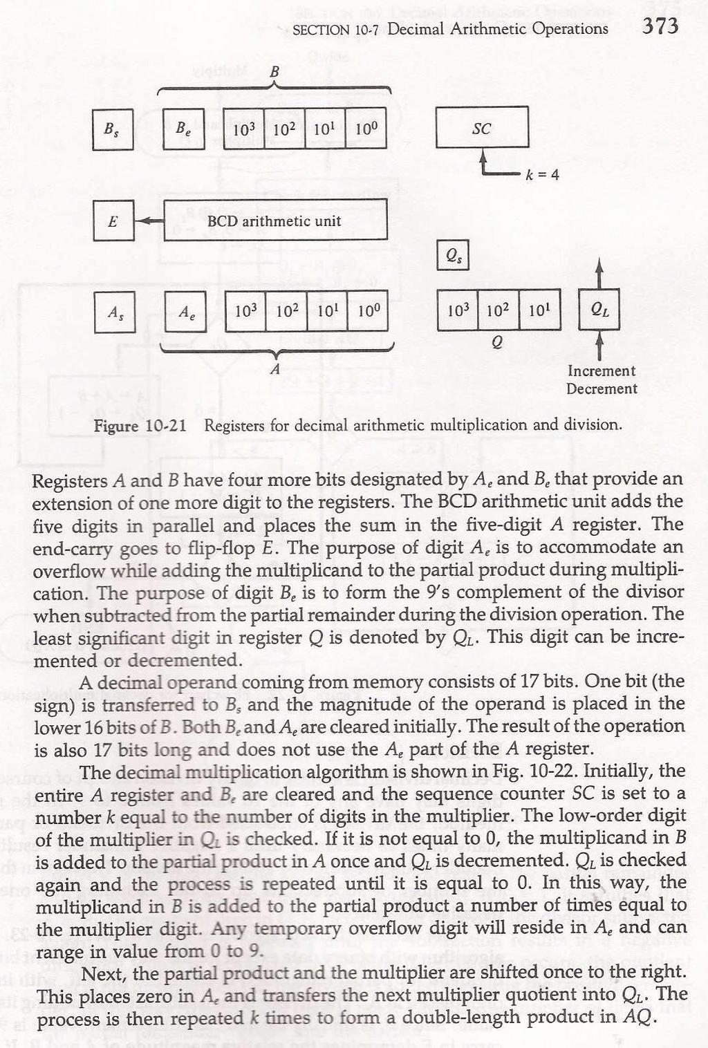
21 Lecture-7 Multiplication Algorithm: Hardware implementation of multiplication of numbers in signed magnitude form: 1. A adder is provided to add two binary numbers and the partial product is accumulated in a register. 2. Instead of shifting the multiplicand to the left, the partial product is shifted to the right, which result in leaving the partial product and the multiplicand in the required relative positions. 3. When the corresponding bit of the multiplier is zero, there is no need to add all zeros to the partial product, since it will not alter it s value. The hardware consists of 4 flipflops, 3 registers, one sequence counter, an adder and complementer. Q register&q S flip flop : contains multiplier & Its sign Sequence counter : It is set to a value equal to the number of bits in the multiplier B Register& B S flipflop : It contains the multiplicand,& its sign A Register, E Flip flop : Initialized to 0. A S denotes sign of partial product EA Register : hold partial product, with carry generated in addition being shifted to E. Qn : Rightmost bit of the multiplier; AQ : will contain the final product. As AQ represent product register, both A S Q S represent the sign of the partial product or product. The number to be multiplied are stores in memory as n bit sign magnitude numbers and when transferred to register msb bit go to sign flipflop and remaining n-1 bits go to registers. Hence SC is initially set to n-1. Let the lower order bit of the multiplier in Q n tested. If it is 1, the multiplicand in B is added to the present partial product in A. If it is a 0, nothing is done. Register EAQ is then shifted once to the right to form the new partial product. The sequence counter is decremented by 1 and it s new value checked. If it is not equal to zero, the process is repeated and a new partial product is formed. The process stops when SC = 0.
22 The final product is available in both A and Q, with A holding the most significant bits and Q holding the least significant bits. Flowchart for multiply operation: Numerical Example for the above algorithm: Multiplicand B= E A Q SC Multiplier in Q Q n =1;add B First Partial Product Shift Right EAQ Q n =1;add B Second Partial Product
23 Shift Right EAQ Q n =0; Shift Right EAQ Q n =0; Shift Right EAQ Q n =1;add B Fifth Partial Product Shift Right EAQ Final Product in AQ AQ = lecture-7.docx Lecture-8 Booth Multiplication Algorithm: Multiplication of signed- 2 s complement integers: This algorithm uses the following facts. 1. A string of 0 s in the multiplier requires no addition but just shifting. 2. A string of 1 s in the multiplier from bit weight 2 k to weight 2 m can be treated as 2 k+1-2 m. Example: Consider the binary number: ( +14 ) The number has a string of 1 s from 2 3 to 2 1. Hence k = 3 and m= 1. As other bits are 0 s, the number can be represented as 2 k+1-2 m = = 16-2 = 14. Therefore the multiplication M * 14, where M is the multiplicand and 14 the multiplier can be done as Mx 2 4 M x 2 1. This can be achieved by shifting binary multiplicand M four times to the left and subtracting M shifted left once which is equal to (Mx 2 4 M x 2 1. ). Shifting and addition/subtraction rules for multiplicand in Booth s Algorithm: 1. The multiplicand is subtracted from the partial product upon encountering the first least significand 1 in a string of I s in the multiplier.
24 2. The multiplicand is added to the partial product upon encountering the first 0 ( provided that there was a previous 1)in a string of 0 s in the multiplier. 3. The partial product does not change when the multiplier bit is identical to the previous multiplier bit Hardware Implementation of Booth Algorithm: Note: Sign bit is not separated from register. QR register contains the multiplier register and Q n represent the least significant bit of the multiplier in QR. Q n+1 is an extra flip flop appended to QR to facilitate a double bit inspection of the multiplier. AC register and appended Q n+1 are initially cleared to 0. Sequence counter Sc is set to the number n which is equal to the number of bits of bits In the multiplier. Q n Q n+1 are to successive bits in the multiplier Example for multiplication using Boot h algorithm: Q n Q n+1 BR = 1011,BR +1 = AC QR Q n+1 SC 10 Initial Subtract BR ashr ashr Add BR ashr ashr Subtract BR 01001
25 Ashr Algorithm in flowchart for multiplication of signed 2 s complement numbers. Array Multiplier: 2 -bit by 2- bit Array Multiplier: Multiplicand bits are b 1 and b 0.Multiplier bits are a 1 and a 0. The first partial product is obtained by multiplying a 0 by b 1 b 0. The bit multiplication is implemented by AND gate. First partial product is made by two AND gates. Second partial product is made by two AND gates. The two partial products are added with two half adder circuits.

26 Combinational circuit binary multiplier: A bit of the multiplier is ANDed with each bit of the multiplicand in as many levels as there bits in the multiplier. The binary output in each level of the AND gates is added in parallel with the partial product of the previous level to form a ne partial product. The last level produces the product. For j multiplier and k multiplicand bits, we need j*k AND Gates and (j-1)*k bit adders to ptoduce a product of j+k bits. 4- bit by 3-bit Array Multiplier: lecture-8.docx

27 Lecture-9 Division Algorithms: Division Process for division of fixed point binary number in signed magnitude representation: Let dividend A consists of 10 bits and divisor B consists of 5 bits. 1. Compare the 5 most significant bits of the dividend with that of divisor. 2. If the 5 bit number is smaller than divisor B, then take 6 bits of the dividend and compare with the 5 bit divisor. 3. The 6 bit number is greater than divisor B. Hence place a 1 for the quotient bit in the sixth position above the dividend. Shift the divisor once to the right and subtracted from the dividend. The difference is called partial remainder. 4. Repeat the process with the partial remainder and divisor. If the partial remainder is equal or greater than or equal to the divisor, the quotient bit is equal to 1.The divisor is then shifted right and subtracted from the partial remainder. If the partial remainder is small than the divisor, then the quotient bit is zero and no subtraction is needed. The divisor is shifted once to the right in any case,. Hardware Implementation of division for signed magnitude fixed point numbers: To implement division using a digital computer, the process is changed slightly for convenience. 1. Instead of shifting the divisor to the right, the dividend or the partial remainder, is shifted to the left so as to leave the two numbers in the required relative position. 2. Subtraction may be achieved by adding A (dividend)to the 2 s complement of B(divisor). The information about the relative magnitude is then available from end carry. 3. Register EAQ is now shifted to the left with 0 inserted into Q n and the previous value of E is lost.. 4. The divisor is stored in B register and the double length dividend is stored in registers A and Q. 5. The dividend is shifted to the left and the divisor is subtracted by adding it s 2 s complement value. 6. If E= 1, it signifies that A B.A quotient bit is inserted into Q n and the partial remainder is shifted to the left to repeat the process. 7. If E = 0, it signifies that A < B so the quotient Q n remains 0( inserted during the shift). The value of B is then added to restore the partial remainder in A to its previous value. The partial remainder is shifted to the left and the process is repeated again until all 5 quotient bits are formed. 8. At the end Q contains the quotient and A the remainder. If the sign of dividend and divisor are alike, the quotient is positive and if unalike, it is negative. The sign of the remainder is the same as dividend.
28 B Register Sequence Counter( SC) Complementer and parallel adder Qn A S Q S E A Register Q Register 0 Hardware for implementing division of fixed point signed- Magnitude Numbers Example of Binary division with digital hardware: Divisor B = 10001, B + 1 = E A Q SC Dividend: Shl EAQ Add, B E = Set Q n = Shl EAQ Add, B E = Set Q n = Shl EAQ Add, B E= 0; Leave Q n = Add B 10001
29 Restore remainder Shl EAQ Add, B E = Set Q n = Shl EAQ Add, B E= 0; Leave Q n = Add B Restore remainder Neglect E Remainder in A Quotient in Q Divide overflow: When the dividend is twice as long as the divisor, the condition for overflow can be stated as follows: A divide-overflow condition occurs if the higher order half bits of the dividend constitute a number greater than or equal to the divisor. If the divisor is zero, then the dividend will definitely be greater than or equal to divisor. Hence divide overflow condition occurs and hence the divide-overflow flip flop will be set. Let the flip flop be called DVF. Handling DVF: 1. Check if DVF is set after each divide instruction. If DVF is set, then the program branches to a subroutine that takes corrective measures such as rescaling the data to avoid overflow. 2. An interrupt is generated if DVF is set. The interrupt causes the processor to suspend the current program and branch to interrupt service routine to take corrective measure. The most
30 common corrective measure is to remove the program and type an error message that explains the reasons. 3. The divide overflow can be handled very simply if the numbers are represented in floating point representation. Flow chart for divide operation: Assumption: Operands are transferred from memory to registers as n bit words.n-1 bit form magnitude and 1 bit shows the sign.
31 A divide overflow condition is tested by subtracting the divisor in B from half of the bits of dividend stored in A. If va B, the DVF is set and the operation is terminated prematurely. If A < B, no DVF occurs and so the value of dividend is restored by adding B to A. The division of the magnitudes starts by shifting the dividend in AQ to the left, with the higher order bit shifted into E. If the bit shifted into E is 1, we know that EA is greater than B because EA consists of a 1 followed by n-1 bits while B consists of only n-1 bits. In this case, B must be subtracted from EA and 1 inserted into Q n for the quotient bit. Since register A is missing the higher order bit of the dividend (which is in E), it s value is EA 2 n-1. Adding to this value the 2 s complement of B results in (EA-2 n-1 ) + ( 2 n-1 B )= E-B. The carry from the addition is not transferred to E if we want E to remain a 1. If the shift left operation inserts a zero into E, the divisor is subtracted by adding it s 2 s complement value and the carry is transferred into E. If E = 1, it signifies that A B and hence Q n is set to 1. If E = 0, it signifies that A < B and the original number is restored by adding B to A. In the latter case we leave a 0 in Q n. ( 0 was inserted during the shift). This process is repeated again with register A holding the partial remainder. After n-1 times, the quotient magnitude is formed in the register Q and the remainder is found in register A. lecture-9.docx Lecture-10 Lecture-10 CO UNIT4 floating point arithmetic.ppt
32
33 2.
34
35
36
37
38
39
40
41

42 Lecture-11 lecture-10.docx
43
44 3.
45
46
47

48 Lecture-12 lecture-11.docx
49

50 Lecture-13 lecture-12.docx
51
52
53
54 2
 s complement of N is defined as e.")
55 lecture-13.docx Test Questions a.docx b.docx true or false.docx Fill in the blanks type of questions <Minimum of ten> a. The decimal representation for hex number F3 is. b. The binary equivalent for the decimal number is c. The BCD code for the decimal number 248 is. d. For a given number N in base r having n digits, the (r-1) s complement of N is defined as e. The 10 s complement of a decimal number is obtained by adding to the 9 s complement value.
56 f. When 2 unsigned numbers are added, an overflow is detected from the of the most significant position. g. An overflow for addition/ subtraction of two signed numbers is detected when the carry into the sign bit position and carry out of the sign bit position are. h. Booth multiplication algorithm is followed when the binary integers are represented in i. When Booth algorithm is used for multiplication, the partial product does not change when the multiplier.is identical to the previous multiplier. j. Floating point multiplication and division do not require an alignment of the. Answers: ( 1). 243 (2) (3) (4) ( r n -1)-N (5) 1 (6) carry out (7) not equal (8) signed 2 s complement representation for negative integers. (9) bit, bit (10) mantissa Multiple choice questions<minimum of ten> 1. Floating point representation is used to store (A) Boolean values (B) whole numbers (C) real integers (D) integers Ans: C 2. In computers, subtraction is generally carried out by (A) 9 s complement (B) 10 s complement (C) 1 s complement (D) 2 s complement Ans: D 3. The circuit used to store one bit of data is known as (A) Register (B) Encoder (C) Decoder (D) Flip Flop Ans: D 4. Which of the following is not a weighted code? (A) Decimal Number system (B) Excess 3-cod (C) Binary number System (D) None of these Ans: B 5. Assembly language (A) uses alphabetic codes in place of binary numbers used in machine language (B) is the easiest language to write programs (C) need not be translated into machine language
57 (D) None of these Ans: A 6. The multiplicand register & multiplier register of a hardware circuit implementing booth's algorithm have (11101) & (1100). The result shall be (A) (812) 10 (B) (-12) 10 (C) (12) 10 (D) (-812) 10 Ans: A 7. What characteristic of RAM memory makes it not suitable for permanent storage? (A) too slow (B) unreliable (C) it is volatile (D) too bulky Ans: C 8. (2FAOC) 16 is equivalent to (A) ( ) 10 (B) ( ) 2 (C) Both (A) and (B) (D) None of these Ans: B 9. The average time required to reach a storage location in memory and obtain its contents is called the (A) seek time (B) turnaround time (C) access time (D) transfer time Ans: C 10. In signed-magnitude binary division, if the dividend is (11100) 2 and divisor is (10011) 2 then the result is (A) (00100) 2 (B) (10100) 2 (C) (11001) 2 (D) (01100) 2 k. Ans: B True or False questions<minimum of ten> Fill the blank with true or false. 1. EEPROM comes under volatile memory category. 2. Thumb drive or pen drive is semiconductor memory. 3. The control unit generates the appropriate signal at the right moment. 4. While executing a program, CPU brings instruction and data from disk memory. 5. A memory module of capacity 16 * 4, indicates a storage of 128 bits. 6. A memory module of capacity of 1024 locations, the required address bus size is The program counter PC is used to store the address of the next instruction to be fetched from Accumulator..
58 8. For n-bit signed integer, the range of numbers that can be represented is 2 n-1 to 2 n Given a number N in base r having n digits, the (r-1) s complement of N is defined as ( r n -1 ) r. 10. Floating point representation uses mantissa and an exponent part of radix R. Answers: ( 1). false (2) true (3) true (4) false (5) false (6) true (7) false (8) false (9)false (10) true Review Questions a.docx b.docx d.docx e.docx c.docx a. Objective type of questions(very short notes)<minimum of ten> b. Analytical type questions<minimum of ten> c. Essay type Questions<As per requirements> d. Problems<As per required Number> e. Case study<as per required Number> Skill Building Exercises/Assignments a. Take the mother board of a computer and identify CPU, memory, peripheral ICs, BUS etc. b. Buy the components of a computer, assemble, install the software and make it to function. Eg:- -Prepare a model of something -Trace something -Prepare a report on something etc., Previous Questions (Asked by JNTUK from the concerned Unit) JNTUK questions unit-1.docx GATE Questions (Where relevant)
59 Subject is not in gate syllabus Interview questions (which are frequently asked in a Technical round-placements) docx Real-Word (Live) Examples/Case studies wherever applicable a. List out the intel CPUs in various generation with their specifications. Write how the performance was improved in each generation Suggested Expert Guest Lectures (both from in and outside of the campus) Literature references of Relevant NPTEL Videos/Web/You Tube videos etc. neptel vidieo ref.docx Any Lab requirements; if so link it to Lab Lesson Plan. No Reference Text Books / with Journals Chapters etc. T1: M. Moris Mano (2006), Computer System Architecture, 3 rd edition, Pearson/PHI, India. T2: Carl Hamacher, ZvonksVranesic, SafeaZaky (2002), Computer Organization, 5 th edition, McGraw Hill, New Delhi, India R1: Computer Organization Architecture- William Stallings (2006), 7 th edition, PHI/PEARSON.
UNIT - I: COMPUTER ARITHMETIC, REGISTER TRANSFER LANGUAGE & MICROOPERATIONS
 UNIT - I: COMPUTER ARITHMETIC, REGISTER TRANSFER LANGUAGE & MICROOPERATIONS (09 periods) Computer Arithmetic: Data Representation, Fixed Point Representation, Floating Point Representation, Addition and
CHETTINAD COLLEGE OF ENGINEERING AND TECHNOLOGY COMPUTER ARCHITECURE- III YEAR EEE-6 TH SEMESTER 16 MARKS QUESTION BANK UNIT-1
 CHETTINAD COLLEGE OF ENGINEERING AND TECHNOLOGY COMPUTER ARCHITECURE- III YEAR EEE-6 TH SEMESTER 16 MARKS QUESTION BANK UNIT-1 Data representation: (CHAPTER-3) 1. Discuss in brief about Data types, (8marks)
PART A (22 Marks) 2. a) Briefly write about r's complement and (r-1)'s complement. [8] b) Explain any two ways of adding decimal numbers.
![PART A (22 Marks) 2. a) Briefly write about r's complement and (r-1)'s complement. [8] b) Explain any two ways of adding decimal numbers.](/thumbs/96/128058841.jpg "PART A (22 Marks) 2. a) Briefly write about r's complement and (r-1)'s complement. [8] b) Explain any two ways of adding decimal numbers.") Set No. 1 IV B.Tech I Semester Supplementary Examinations, March - 2017 COMPUTER ARCHITECTURE & ORGANIZATION (Common to Electronics & Communication Engineering and Electronics & Time: 3 hours Max. Marks:
Set No. 1 IV B.Tech I Semester Supplementary Examinations, March - 2017 COMPUTER ARCHITECTURE & ORGANIZATION (Common to Electronics & Communication Engineering and Electronics & Time: 3 hours Max. Marks:
COMPUTER ARCHITECTURE AND ORGANIZATION. Operation Add Magnitudes Subtract Magnitudes (+A) + ( B) + (A B) (B A) + (A B)
 + ( B) + (A B) (B A) + (A B)") Computer Arithmetic Data is manipulated by using the arithmetic instructions in digital computers. Data is manipulated to produce results necessary to give solution for the computation problems. The Addition,
Computer Arithmetic Data is manipulated by using the arithmetic instructions in digital computers. Data is manipulated to produce results necessary to give solution for the computation problems. The Addition,
(+A) + ( B) + (A B) (B A) + (A B) ( A) + (+ B) (A B) + (B A) + (A B) (+ A) (+ B) + (A - B) (B A) + (A B) ( A) ( B) (A B) + (B A) + (A B)
 + ( B) + (A B) (B A) + (A B) ( A) + (+ B) (A B) + (B A) + (A B) (+ A) (+ B) + (A - B) (B A) + (A B) ( A) ( B) (A B) + (B A) + (A B)") COMPUTER ARITHMETIC 1. Addition and Subtraction of Unsigned Numbers The direct method of subtraction taught in elementary schools uses the borrowconcept. In this method we borrow a 1 from a higher significant
COMPUTER ARITHMETIC 1. Addition and Subtraction of Unsigned Numbers The direct method of subtraction taught in elementary schools uses the borrowconcept. In this method we borrow a 1 from a higher significant
Course Description: This course includes concepts of instruction set architecture,
 Computer Architecture Course Title: Computer Architecture Full Marks: 60+ 20+20 Course No: CSC208 Pass Marks: 24+8+8 Nature of the Course: Theory + Lab Credit Hrs: 3 Course Description: This course includes
Computer Organisation CS303
 Computer Organisation CS303 Module Period Assignments 1 Day 1 to Day 6 1. Write a program to evaluate the arithmetic statement: X=(A-B + C * (D * E-F))/G + H*K a. Using a general register computer with
COMPUTER ORGANIZATION AND ARCHITECTURE
 COMPUTER ORGANIZATION AND ARCHITECTURE For COMPUTER SCIENCE COMPUTER ORGANIZATION. SYLLABUS AND ARCHITECTURE Machine instructions and addressing modes, ALU and data-path, CPU control design, Memory interface,
SRM ARTS AND SCIENCE COLLEGE SRM NAGAR, KATTANKULATHUR
 SRM ARTS AND SCIENCE COLLEGE SRM NAGAR, KATTANKULATHUR 603203 DEPARTMENT OF COMPUTER SCIENCE & APPLICATIONS LESSON PLAN (207-208) Course / Branch : M.Sc CST Total Hours : 50 Subject Name : Computer Architecture
COMPUTER ORGANIZATION AND ARCHITECTURE
 Page 1 1. Which register store the address of next instruction to be executed? A) PC B) AC C) SP D) NONE 2. How many bits are required to address the 128 words of memory? A) 7 B) 8 C) 9 D) NONE 3. is the
INTELLIGENCE PLUS CHARACTER - THAT IS THE GOAL OF TRUE EDUCATION UNIT-I
 UNIT-I 1. List and explain the functional units of a computer with a neat diagram 2. Explain the computer levels of programming languages 3. a) Explain about instruction formats b) Evaluate the arithmetic
D I G I T A L C I R C U I T S E E
 D I G I T A L C I R C U I T S E E Digital Circuits Basic Scope and Introduction This book covers theory solved examples and previous year gate question for following topics: Number system, Boolean algebra,
SIDDHARTH GROUP OF INSTITUTIONS :: PUTTUR Siddharth Nagar, Narayanavanam Road QUESTION BANK (DESCRIPTIVE) UNIT-I
 UNIT-I") SIDDHARTH GROUP OF INSTITUTIONS :: PUTTUR Siddharth Nagar, Narayanavanam Road 517583 QUESTION BANK (DESCRIPTIVE) Subject with Code : CO (16MC802) Year & Sem: I-MCA & I-Sem Course & Branch: MCA Regulation:
SIDDHARTH GROUP OF INSTITUTIONS :: PUTTUR Siddharth Nagar, Narayanavanam Road 517583 QUESTION BANK (DESCRIPTIVE) Subject with Code : CO (16MC802) Year & Sem: I-MCA & I-Sem Course & Branch: MCA Regulation:
CHW 261: Logic Design
 CHW 261: Logic Design Instructors: Prof. Hala Zayed Dr. Ahmed Shalaby http://www.bu.edu.eg/staff/halazayed14 http://bu.edu.eg/staff/ahmedshalaby14# Slide 1 Slide 2 Slide 3 Digital Fundamentals CHAPTER
UNIT-IV COMPUTER ARITHMETIC
 UNIT-IV COMPUTER ARITHMETIC Introduction: Data is manipulated by using the arithmetic instructions in digital computers. Data is manipulated to produce results necessary to give solution for the computation
Chapter 5 : Computer Arithmetic
 Chapter 5 Computer Arithmetic Integer Representation: (Fixedpoint representation): An eight bit word can be represented the numbers from zero to 255 including = 1 = 1 11111111 = 255 In general if an nbit
Computer Organization
 Computer Organization It describes the function and design of the various units of digital computers that store and process information. It also deals with the units of computer that receive information
Chapter 10 - Computer Arithmetic
 Chapter 10 - Computer Arithmetic Luis Tarrataca luis.tarrataca@gmail.com CEFET-RJ L. Tarrataca Chapter 10 - Computer Arithmetic 1 / 126 1 Motivation 2 Arithmetic and Logic Unit 3 Integer representation
Module 2: Computer Arithmetic
 Module 2: Computer Arithmetic 1 B O O K : C O M P U T E R O R G A N I Z A T I O N A N D D E S I G N, 3 E D, D A V I D L. P A T T E R S O N A N D J O H N L. H A N N E S S Y, M O R G A N K A U F M A N N
SYLLABUS. osmania university CHAPTER - 1 : REGISTER TRANSFER LANGUAGE AND MICRO OPERATION CHAPTER - 2 : BASIC COMPUTER
 Contents i SYLLABUS osmania university UNIT - I CHAPTER - 1 : REGISTER TRANSFER LANGUAGE AND MICRO OPERATION Difference between Computer Organization and Architecture, RTL Notation, Common Bus System using
CHAPTER TWO. Data Representation ( M.MORRIS MANO COMPUTER SYSTEM ARCHITECTURE THIRD EDITION ) IN THIS CHAPTER
 IN THIS CHAPTER") 1 CHAPTER TWO Data Representation ( M.MORRIS MANO COMPUTER SYSTEM ARCHITECTURE THIRD EDITION ) IN THIS CHAPTER 2-1 Data Types 2-2 Complements 2-3 Fixed-Point Representation 2-4 Floating-Point Representation
1 CHAPTER TWO Data Representation ( M.MORRIS MANO COMPUTER SYSTEM ARCHITECTURE THIRD EDITION ) IN THIS CHAPTER 2-1 Data Types 2-2 Complements 2-3 Fixed-Point Representation 2-4 Floating-Point Representation
JNTUWORLD. 1. Discuss in detail inter processor arbitration logics and procedures with necessary diagrams? [15]
![JNTUWORLD. 1. Discuss in detail inter processor arbitration logics and procedures with necessary diagrams? [15]](/thumbs/96/128058746.jpg "JNTUWORLD. 1. Discuss in detail inter processor arbitration logics and procedures with necessary diagrams? [15]") Code No: 09A50402 R09 Set No. 2 1. Discuss in detail inter processor arbitration logics and procedures with necessary diagrams? [15] 2. (a) Discuss asynchronous serial transfer concept? (b) Explain in
Code No: 09A50402 R09 Set No. 2 1. Discuss in detail inter processor arbitration logics and procedures with necessary diagrams? [15] 2. (a) Discuss asynchronous serial transfer concept? (b) Explain in
Digital Fundamentals
 Digital Fundamentals Tenth Edition Floyd Chapter 2 2009 Pearson Education, Upper 2008 Pearson Saddle River, Education NJ 07458. All Rights Reserved Decimal Numbers The position of each digit in a weighted
COURSE DESCRIPTION. CS 232 Course Title Computer Organization. Course Coordinators
 COURSE DESCRIPTION Dept., Number Semester hours CS 232 Course Title Computer Organization 4 Course Coordinators Badii, Joseph, Nemes 2004-2006 Catalog Description Comparative study of the organization
Computer Architecture
 Computer Architecture Lecture 1: Digital logic circuits The digital computer is a digital system that performs various computational tasks. Digital computers use the binary number system, which has two
CPE300: Digital System Architecture and Design
 CPE300: Digital System Architecture and Design Fall 2011 MW 17:30-18:45 CBC C316 Arithmetic Unit 10122011 http://www.egr.unlv.edu/~b1morris/cpe300/ 2 Outline Recap Fixed Point Arithmetic Addition/Subtraction
An instruction set processor consist of two important units: Data Processing Unit (DataPath) Program Control Unit
 Program Control Unit") DataPath Design An instruction set processor consist of two important units: Data Processing Unit (DataPath) Program Control Unit Add & subtract instructions for fixed binary numbers are found in the
DataPath Design An instruction set processor consist of two important units: Data Processing Unit (DataPath) Program Control Unit Add & subtract instructions for fixed binary numbers are found in the
BINARY SYSTEM. Binary system is used in digital systems because it is:
 CHAPTER 2 CHAPTER CONTENTS 2.1 Binary System 2.2 Binary Arithmetic Operation 2.3 Signed & Unsigned Numbers 2.4 Arithmetic Operations of Signed Numbers 2.5 Hexadecimal Number System 2.6 Octal Number System
Computer Arithmetic Ch 8
 Computer Arithmetic Ch 8 ALU Integer Representation Integer Arithmetic Floating-Point Representation Floating-Point Arithmetic 1 Arithmetic Logical Unit (ALU) (2) Does all work in CPU (aritmeettis-looginen
SAE5C Computer Organization and Architecture. Unit : I - V
 SAE5C Computer Organization and Architecture Unit : I - V UNIT-I Evolution of Pentium and Power PC Evolution of Computer Components functions Interconnection Bus Basics of PCI Memory:Characteristics,Hierarchy
1. NUMBER SYSTEMS USED IN COMPUTING: THE BINARY NUMBER SYSTEM
 1. NUMBER SYSTEMS USED IN COMPUTING: THE BINARY NUMBER SYSTEM 1.1 Introduction Given that digital logic and memory devices are based on two electrical states (on and off), it is natural to use a number
UNIT-II. Part-2: CENTRAL PROCESSING UNIT
 Page1 UNIT-II Part-2: CENTRAL PROCESSING UNIT Stack Organization Instruction Formats Addressing Modes Data Transfer And Manipulation Program Control Reduced Instruction Set Computer (RISC) Introduction:
TYPICAL QUESTIONS & ANSWERS
 TYPICAL QUESTIONS & ANSWERS PART-I Each Question carries 2 marks. OBJECTIVE TYPE QUESTIONS Choose the correct or best alternative in the following: Q.1 In Reverse Polish notation, expression A*B+C*D is
Numbering systems. Dr Abu Arqoub
 Numbering systems The decimal numbering system is widely used, because the people Accustomed (معتاد) to use the hand fingers in their counting. But with the development of the computer science another
The ALU consists of combinational logic. Processes all data in the CPU. ALL von Neuman machines have an ALU loop.
 CS 320 Ch 10 Computer Arithmetic The ALU consists of combinational logic. Processes all data in the CPU. ALL von Neuman machines have an ALU loop. Signed integers are typically represented in sign-magnitude
Computer Arithmetic Ch 8
 Computer Arithmetic Ch 8 ALU Integer Representation Integer Arithmetic Floating-Point Representation Floating-Point Arithmetic 1 Arithmetic Logical Unit (ALU) (2) (aritmeettis-looginen yksikkö) Does all
DC57 COMPUTER ORGANIZATION JUNE 2013
 Q2 (a) How do various factors like Hardware design, Instruction set, Compiler related to the performance of a computer? The most important measure of a computer is how quickly it can execute programs.
Divide: Paper & Pencil
 Divide: Paper & Pencil 1001 Quotient Divisor 1000 1001010 Dividend -1000 10 101 1010 1000 10 Remainder See how big a number can be subtracted, creating quotient bit on each step Binary => 1 * divisor or
Computer Architecture: Part V. First Semester 2013 Department of Computer Science Faculty of Science Chiang Mai University
 Computer Architecture: Part V First Semester 2013 Department of Computer Science Faculty of Science Chiang Mai University Outline Addition and Subtraction Multiplication Algorithm Array Multiplier Peripheral
PESIT Bangalore South Campus
 INTERNAL ASSESSMENT TEST III Date : 21/11/2017 Max Marks : 40 Subject & Code : Computer Organization (15CS34) Semester : III (A & B) Name of the faculty: Mrs. Sharmila Banu Time : 11.30 am 1.00 pm Answer
Organisasi Sistem Komputer
 LOGO Organisasi Sistem Komputer OSK 8 Aritmatika Komputer 1 1 PT. Elektronika FT UNY Does the calculations Arithmetic & Logic Unit Everything else in the computer is there to service this unit Handles
Number Systems and Computer Arithmetic
 Number Systems and Computer Arithmetic Counting to four billion two fingers at a time What do all those bits mean now? bits (011011011100010...01) instruction R-format I-format... integer data number text
2. (a) Compare the characteristics of a floppy disk and a hard disk. (b) Discuss in detail memory interleaving. [8+7]
![2. (a) Compare the characteristics of a floppy disk and a hard disk. (b) Discuss in detail memory interleaving. [8+7]](/thumbs/96/127320205.jpg "2. (a) Compare the characteristics of a floppy disk and a hard disk. (b) Discuss in detail memory interleaving. [8+7]") Code No: A109211202 R09 Set No. 2 1. (a) Explain the purpose of the following registers: i. IR ii. PC iii. MDR iv. MAR. (b) Explain with an example the steps in subtraction of two n-digit unsigned numbers.
Code No: A109211202 R09 Set No. 2 1. (a) Explain the purpose of the following registers: i. IR ii. PC iii. MDR iv. MAR. (b) Explain with an example the steps in subtraction of two n-digit unsigned numbers.
2 MARKS Q&A 1 KNREDDY UNIT-I
 2 MARKS Q&A 1 KNREDDY UNIT-I 1. What is bus; list the different types of buses with its function. A group of lines that serves as a connecting path for several devices is called a bus; TYPES: ADDRESS BUS,
CO212 Lecture 10: Arithmetic & Logical Unit
 CO212 Lecture 10: Arithmetic & Logical Unit Shobhanjana Kalita, Dept. of CSE, Tezpur University Slides courtesy: Computer Architecture and Organization, 9 th Ed, W. Stallings Integer Representation For
UNIT-III COMPUTER ARTHIMETIC
 UNIT-III COMPUTER ARTHIMETIC INTRODUCTION Arithmetic Instructions in digital computers manipulate data to produce results necessary for the of activity solution of computational problems. These instructions
Floating-Point Data Representation and Manipulation 198:231 Introduction to Computer Organization Lecture 3
 Floating-Point Data Representation and Manipulation 198:231 Introduction to Computer Organization Instructor: Nicole Hynes nicole.hynes@rutgers.edu 1 Fixed Point Numbers Fixed point number: integer part
COMPUTER ARCHITECTURE AND ORGANIZATION Register Transfer and Micro-operations 1. Introduction A digital system is an interconnection of digital
 Register Transfer and Micro-operations 1. Introduction A digital system is an interconnection of digital hardware modules that accomplish a specific information-processing task. Digital systems vary in
The functional block diagram of 8085A is shown in fig.4.1.
 Lecture-13 Internal Architecture of Intel 05A The functional block diagram of 05A is shown in fig.4.1. INTA INTR RST7.5 RST5.5 RST6.5 TRAP SOD SID INTERRUPT SERIAL I/O (Internal Bus) FR(S) IR() B() C()
COA. Prepared By: Dhaval R. Patel Page 1. Q.1 Define MBR.
 Q.1 Define MBR. MBR( Memory buffer register) A Memory Buffer Register (MBR) is the register in a computers processor that stores the data being transferred to and from the devices It allowing the processor
UNIT I DATA REPRESENTATION, MICRO-OPERATIONS, ORGANIZATION AND DESIGN
 UNIT I DATA REPRESENTATION, MICRO-OPERATIONS, ORGANIZATION AND DESIGN Data representation: Data types, complements, fixed point representation, floating-point representation, other binary codes, error
Chapter 2. Data Representation in Computer Systems
 Chapter 2 Data Representation in Computer Systems Chapter 2 Objectives Understand the fundamentals of numerical data representation and manipulation in digital computers. Master the skill of converting
MACHINE LEVEL REPRESENTATION OF DATA
 MACHINE LEVEL REPRESENTATION OF DATA CHAPTER 2 1 Objectives Understand how integers and fractional numbers are represented in binary Explore the relationship between decimal number system and number systems
Advanced Parallel Architecture Lesson 3. Annalisa Massini /2015
 Advanced Parallel Architecture Lesson 3 Annalisa Massini - 2014/2015 Von Neumann Architecture 2 Summary of the traditional computer architecture: Von Neumann architecture http://williamstallings.com/coa/coa7e.html
9/3/2015. Data Representation II. 2.4 Signed Integer Representation. 2.4 Signed Integer Representation
 Data Representation II CMSC 313 Sections 01, 02 The conversions we have so far presented have involved only unsigned numbers. To represent signed integers, computer systems allocate the high-order bit
Arithmetic Logic Unit
 Arithmetic Logic Unit A.R. Hurson Department of Computer Science Missouri University of Science & Technology A.R. Hurson 1 Arithmetic Logic Unit It is a functional bo designed to perform "basic" arithmetic,
Number Systems Standard positional representation of numbers: An unsigned number with whole and fraction portions is represented as:
 N Number Systems Standard positional representation of numbers: An unsigned number with whole and fraction portions is represented as: a n a a a The value of this number is given by: = a n Ka a a a a a
CPE 323 REVIEW DATA TYPES AND NUMBER REPRESENTATIONS IN MODERN COMPUTERS
 CPE 323 REVIEW DATA TYPES AND NUMBER REPRESENTATIONS IN MODERN COMPUTERS Aleksandar Milenković The LaCASA Laboratory, ECE Department, The University of Alabama in Huntsville Email: milenka@uah.edu Web:
Internal Data Representation
 Appendices This part consists of seven appendices, which provide a wealth of reference material. Appendix A primarily discusses the number systems and their internal representation. Appendix B gives information
CPE 323 REVIEW DATA TYPES AND NUMBER REPRESENTATIONS IN MODERN COMPUTERS
 CPE 323 REVIEW DATA TYPES AND NUMBER REPRESENTATIONS IN MODERN COMPUTERS Aleksandar Milenković The LaCASA Laboratory, ECE Department, The University of Alabama in Huntsville Email: milenka@uah.edu Web:
Principles of Computer Architecture. Chapter 3: Arithmetic
 3-1 Chapter 3 - Arithmetic Principles of Computer Architecture Miles Murdocca and Vincent Heuring Chapter 3: Arithmetic 3-2 Chapter 3 - Arithmetic 3.1 Overview Chapter Contents 3.2 Fixed Point Addition
COMPUTER ARITHMETIC (Part 1)
") Eastern Mediterranean University School of Computing and Technology ITEC255 Computer Organization & Architecture COMPUTER ARITHMETIC (Part 1) Introduction The two principal concerns for computer arithmetic
Eastern Mediterranean University School of Computing and Technology ITEC255 Computer Organization & Architecture COMPUTER ARITHMETIC (Part 1) Introduction The two principal concerns for computer arithmetic
Advanced Parallel Architecture Lesson 3. Annalisa Massini /2015
 Advanced Parallel Architecture Lesson 3 Annalisa Massini - Von Neumann Architecture 2 Two lessons Summary of the traditional computer architecture Von Neumann architecture http://williamstallings.com/coa/coa7e.html
Honorary Professor Supercomputer Education and Research Centre Indian Institute of Science, Bangalore
 COMPUTER ORGANIZATION AND ARCHITECTURE V. Rajaraman Honorary Professor Supercomputer Education and Research Centre Indian Institute of Science, Bangalore T. Radhakrishnan Professor of Computer Science
Chapter 3 Arithmetic for Computers (Part 2)
") Department of Electr rical Eng ineering, Chapter 3 Arithmetic for Computers (Part 2) 王振傑 (Chen-Chieh Wang) ccwang@mail.ee.ncku.edu.tw ncku edu Depar rtment of Electr rical Eng ineering, Feng-Chia Unive
Department of Electr rical Eng ineering, Chapter 3 Arithmetic for Computers (Part 2) 王振傑 (Chen-Chieh Wang) ccwang@mail.ee.ncku.edu.tw ncku edu Depar rtment of Electr rical Eng ineering, Feng-Chia Unive
MIPS Integer ALU Requirements
 MIPS Integer ALU Requirements Add, AddU, Sub, SubU, AddI, AddIU: 2 s complement adder/sub with overflow detection. And, Or, Andi, Ori, Xor, Xori, Nor: Logical AND, logical OR, XOR, nor. SLTI, SLTIU (set
M. Sc (CS) (II Semester) Examination, Subject: Computer System Architecture Paper Code: M.Sc-CS-203. Time: Three Hours] [Maximum Marks: 60
![M. Sc (CS) (II Semester) Examination, Subject: Computer System Architecture Paper Code: M.Sc-CS-203. Time: Three Hours] [Maximum Marks: 60](/thumbs/87/96339673.jpg "M. Sc (CS) (II Semester) Examination, Subject: Computer System Architecture Paper Code: M.Sc-CS-203. Time: Three Hours] [Maximum Marks: 60") M. Sc (CS) (II Semester) Examination, 2012-13 Subject: Computer System Architecture Paper Code: M.Sc-CS-203 Time: Three Hours] [Maximum Marks: 60 Note: Question Number 1 is compulsory. Answer any four
M. Sc (CS) (II Semester) Examination, 2012-13 Subject: Computer System Architecture Paper Code: M.Sc-CS-203 Time: Three Hours] [Maximum Marks: 60 Note: Question Number 1 is compulsory. Answer any four
CHAPTER 2 Data Representation in Computer Systems
 CHAPTER 2 Data Representation in Computer Systems 2.1 Introduction 37 2.2 Positional Numbering Systems 38 2.3 Decimal to Binary Conversions 38 2.3.1 Converting Unsigned Whole Numbers 39 2.3.2 Converting
Floating Point Arithmetic
 Floating Point Arithmetic CS 365 Floating-Point What can be represented in N bits? Unsigned 0 to 2 N 2s Complement -2 N-1 to 2 N-1-1 But, what about? very large numbers? 9,349,398,989,787,762,244,859,087,678
EE260: Logic Design, Spring n Integer multiplication. n Booth s algorithm. n Integer division. n Restoring, non-restoring
 EE 260: Introduction to Digital Design Arithmetic II Yao Zheng Department of Electrical Engineering University of Hawaiʻi at Mānoa Overview n Integer multiplication n Booth s algorithm n Integer division
Inf2C - Computer Systems Lecture 2 Data Representation
 Inf2C - Computer Systems Lecture 2 Data Representation Boris Grot School of Informatics University of Edinburgh Last lecture Moore s law Types of computer systems Computer components Computer system stack
Digital Fundamentals. CHAPTER 2 Number Systems, Operations, and Codes
 Digital Fundamentals CHAPTER 2 Number Systems, Operations, and Codes Decimal Numbers The decimal number system has ten digits: 0, 1, 2, 3, 4, 5, 6, 7, 8, and 9 The decimal numbering system has a base of
Chapter 2. Data Representation in Computer Systems
 Chapter 2 Data Representation in Computer Systems Chapter 2 Objectives Understand the fundamentals of numerical data representation and manipulation in digital computers. Master the skill of converting
COMPUTER ORGANIZATION AND DESIGN. 5 th Edition. The Hardware/Software Interface. Chapter 3. Arithmetic for Computers Implementation
 COMPUTER ORGANIZATION AND DESIGN The Hardware/Software Interface 5 th Edition Chapter 3 Arithmetic for Computers Implementation Today Review representations (252/352 recap) Floating point Addition: Ripple
Computer Sc. & IT. Digital Logic. Computer Sciencee & Information Technology. 20 Rank under AIR 100. Postal Correspondence
 GATE Postal Correspondence Computer Sc. & IT 1 Digital Logic Computer Sciencee & Information Technology (CS) 20 Rank under AIR 100 Postal Correspondence Examination Oriented Theory, Practice Set Key concepts,
Chapter 03: Computer Arithmetic. Lesson 09: Arithmetic using floating point numbers
 Chapter 03: Computer Arithmetic Lesson 09: Arithmetic using floating point numbers Objective To understand arithmetic operations in case of floating point numbers 2 Multiplication of Floating Point Numbers
CS 5803 Introduction to High Performance Computer Architecture: Arithmetic Logic Unit. A.R. Hurson 323 CS Building, Missouri S&T
 CS 5803 Introduction to High Performance Computer Architecture: Arithmetic Logic Unit A.R. Hurson 323 CS Building, Missouri S&T hurson@mst.edu 1 Outline Motivation Design of a simple ALU How to design
Data Representation Type of Data Representation Integers Bits Unsigned 2 s Comp Excess 7 Excess 8
 Data Representation At its most basic level, all digital information must reduce to 0s and 1s, which can be discussed as binary, octal, or hex data. There s no practical limit on how it can be interpreted
Chapter 3. Arithmetic Text: P&H rev
 Chapter 3 Arithmetic Text: P&H rev3.29.16 Arithmetic for Computers Operations on integers Addition and subtraction Multiplication and division Dealing with overflow Floating-point real numbers Representation
DLD VIDYA SAGAR P. potharajuvidyasagar.wordpress.com. Vignana Bharathi Institute of Technology UNIT 1 DLD P VIDYA SAGAR
 UNIT I Digital Systems: Binary Numbers, Octal, Hexa Decimal and other base numbers, Number base conversions, complements, signed binary numbers, Floating point number representation, binary codes, error
UNIVERSITY OF MASSACHUSETTS Dept. of Electrical & Computer Engineering. Digital Computer Arithmetic ECE 666
 UNIVERSITY OF MASSACHUSETTS Dept. of Electrical & Computer Engineering Digital Computer Arithmetic ECE 666 Part 4-A Floating-Point Arithmetic Israel Koren ECE666/Koren Part.4a.1 Preliminaries - Representation
±M R ±E, S M CHARACTERISTIC MANTISSA 1 k j
 ENEE 350 c C. B. Silio, Jan., 2010 FLOATING POINT REPRESENTATIONS It is assumed that the student is familiar with the discussion in Appendix B of the text by A. Tanenbaum, Structured Computer Organization,
Chapter 4. Operations on Data
 Chapter 4 Operations on Data 1 OBJECTIVES After reading this chapter, the reader should be able to: List the three categories of operations performed on data. Perform unary and binary logic operations
Floating-point Arithmetic. where you sum up the integer to the left of the decimal point and the fraction to the right.
 Floating-point Arithmetic Reading: pp. 312-328 Floating-Point Representation Non-scientific floating point numbers: A non-integer can be represented as: 2 4 2 3 2 2 2 1 2 0.2-1 2-2 2-3 2-4 where you sum
Kinds Of Data CHAPTER 3 DATA REPRESENTATION. Numbers Are Different! Positional Number Systems. Text. Numbers. Other
 Kinds Of Data CHAPTER 3 DATA REPRESENTATION Numbers Integers Unsigned Signed Reals Fixed-Point Floating-Point Binary-Coded Decimal Text ASCII Characters Strings Other Graphics Images Video Audio Numbers
Floating-Point Arithmetic
 ENEE446---Lectures-4/10-15/08 A. Yavuz Oruç Professor, UMD, College Park Copyright 2007 A. Yavuz Oruç. All rights reserved. Floating-Point Arithmetic Integer or fixed-point arithmetic provides a complete
Chapter 4. MARIE: An Introduction to a Simple Computer
 Chapter 4 MARIE: An Introduction to a Simple Computer Chapter 4 Objectives Learn the components common to every modern computer system. Be able to explain how each component contributes to program execution.
MaanavaN.Com CS1202 COMPUTER ARCHITECHTURE
 DEPARTMENT OF COMPUTER SCIENCE AND ENGINEERING QUESTION BANK SUB CODE / SUBJECT: CS1202/COMPUTER ARCHITECHTURE YEAR / SEM: II / III UNIT I BASIC STRUCTURE OF COMPUTER 1. What is meant by the stored program
CHAPTER 2 Data Representation in Computer Systems
 CHAPTER 2 Data Representation in Computer Systems 2.1 Introduction 37 2.2 Positional Numbering Systems 38 2.3 Decimal to Binary Conversions 38 2.3.1 Converting Unsigned Whole Numbers 39 2.3.2 Converting
By, Ajinkya Karande Adarsh Yoga
 By, Ajinkya Karande Adarsh Yoga Introduction Early computer designers believed saving computer time and memory were more important than programmer time. Bug in the divide algorithm used in Intel chips.
s complement 1-bit Booth s 2-bit Booth s
 ECE/CS 552 : Introduction to Computer Architecture FINAL EXAM May 12th, 2002 NAME: This exam is to be done individually. Total 6 Questions, 100 points Show all your work to receive partial credit for incorrect
COMP Overview of Tutorial #2
 COMP 1402 Winter 2008 Tutorial #2 Overview of Tutorial #2 Number representation basics Binary conversions Octal conversions Hexadecimal conversions Signed numbers (signed magnitude, one s and two s complement,
MARIE: An Introduction to a Simple Computer
 MARIE: An Introduction to a Simple Computer Outline Learn the components common to every modern computer system. Be able to explain how each component contributes to program execution. Understand a simple
CHAPTER V NUMBER SYSTEMS AND ARITHMETIC
 CHAPTER V-1 CHAPTER V CHAPTER V NUMBER SYSTEMS AND ARITHMETIC CHAPTER V-2 NUMBER SYSTEMS RADIX-R REPRESENTATION Decimal number expansion 73625 10 = ( 7 10 4 ) + ( 3 10 3 ) + ( 6 10 2 ) + ( 2 10 1 ) +(
DIGITAL SYSTEM FUNDAMENTALS (ECE 421) DIGITAL ELECTRONICS FUNDAMENTAL (ECE 422) COURSE / CODE NUMBER SYSTEM
 DIGITAL ELECTRONICS FUNDAMENTAL (ECE 422) COURSE / CODE NUMBER SYSTEM") COURSE / CODE DIGITAL SYSTEM FUNDAMENTALS (ECE 421) DIGITAL ELECTRONICS FUNDAMENTAL (ECE 422) NUMBER SYSTEM A considerable subset of digital systems deals with arithmetic operations. To understand the
COURSE / CODE DIGITAL SYSTEM FUNDAMENTALS (ECE 421) DIGITAL ELECTRONICS FUNDAMENTAL (ECE 422) NUMBER SYSTEM A considerable subset of digital systems deals with arithmetic operations. To understand the
Thomas Polzer Institut für Technische Informatik
 Thomas Polzer tpolzer@ecs.tuwien.ac.at Institut für Technische Informatik Operations on integers Addition and subtraction Multiplication and division Dealing with overflow Floating-point real numbers VO
Register Transfer and Micro-operations
 Register Transfer Language Register Transfer Bus Memory Transfer Micro-operations Some Application of Logic Micro Operations Register Transfer and Micro-operations Learning Objectives After reading this
Ms Sandhya Rani Dash UNIT 2: NUMBER SYSTEM AND CODES. 1.1 Introduction
 Ms Sandhya Rani Dash UNIT 2: NUMBER SYSTEM AND CODES Structure 2.1 Introduction 2.2 Objectives 2.3 Binary Numbers 2.3.1 Binary-to-Decimal conversion 2.3.2 Decimal-to-Binary Conversion 2.4 Octal Numbers
b) Write basic performance equation.
 Write basic performance equation.") 1. a) What is use of buffers? Ans: The Buffer Register prevents the high speed processor from being locked to a slow I/O device during a sequence of data transfer or reduces speed mismatch between faster
1. a) What is use of buffers? Ans: The Buffer Register prevents the high speed processor from being locked to a slow I/O device during a sequence of data transfer or reduces speed mismatch between faster
Topics. 6.1 Number Systems and Radix Conversion 6.2 Fixed-Point Arithmetic 6.3 Seminumeric Aspects of ALU Design 6.4 Floating-Point Arithmetic
 6-1 Chapter 6 Computer Arithmetic and the Arithmetic Unit Chapter 6: Computer Arithmetic and the Arithmetic Unit Topics 6.1 Number Systems and Radix Conversion 6.2 Fixed-Point Arithmetic 6.3 Seminumeric