Speaker: Shao-Wei Feng Adviser: Prof. An-Yeu Wu Date: 2010/09/28
|
|
|
- Reynard Williamson
- 6 years ago
- Views:
Transcription
1 99-1 Under-Graduate Project Verilog Simulation & Debugging Tools Speaker: Shao-Wei Feng Adviser: Prof. An-Yeu Wu Date: 2010/09/28 ACCESS IC LAB
2 Outline Basic Concept of Verilog HDL Gate Level Modeling Simulation & Verification Summary P. 2
3 What is Verilog HDL? Hardware Description Language Mixed level modeling Behavioral Algorithmic ( like high level language) Register transfer (Synthesizable) Register Transfer Level (RTL) Describing a system by the flow of data and control signals within and between functional blocks Define the model in terms of cycles, based on a defined clock Structural Gate (AND, OR ) Switch (PMOS, NMOS, JFET ) P. 3
4 An Example 1-bit Multiplexer to select output sel sel in1 in2 out in1 in2 0 1 out if (sel==0) out=in1; else out=in2; out = (sel in1) + (sel in2) P. 4
 in the code P.")
5 Gate Level Description in1 in2 iv_sel n1 a1 a2 a1_o a2_o o 1 out sel iv_sel Gate Level: you see only netlist (gates and wires) in the code P. 5
 (cannot be the first character) underscore ( _ ) $ symbol (only for system tasks and functions) Max length of 1024 symbols Terminate lines with semicolon ; Single line comments: // A")
6 Verilog Language Rules Verilog is a case sensitive language (with a few exceptions) Identifiers (space-free sequence of symbols) upper and lower case letters from the alphabet digits (0, 1,..., 9) (cannot be the first character) underscore ( _ ) $ symbol (only for system tasks and functions) Max length of 1024 symbols Terminate lines with semicolon ; Single line comments: // A single-line comment goes here Multi-line comments: /* Multi-line comments like this */ P. 6

7 Verilog HDL Syntax module name in/out port declaration syntax port/wire declaration kernel hardware gate-connection/ behavior P. 7
8 Module Basic building block in Verilog. Module 1. Created by declaration (can t be nested) 2. Used by instantiation Interface is defined by ports May contain instances of other modules All modules run concurrently P. 8
9 Instances A module provides a template from which you can create actual objects. When a module is invoked, Verilog creates a unique object from the template. Each object has its own name, variables, parameters and I/O interface. P. 9


10 Module Instantiation Adder instance example Adder Adder Adder_tree P. 10
 FA1 fa2(.a(a),.b(b),.co(c_o),.ci(c_i),.s(sum)); Recommended P.")
11 Port Connection Connect module port by order list FA1 fa1(c_o, sum, a, b, c_i); Connect module port by name.portname( NetName ) FA1 fa2(.a(a),.b(b),.co(c_o),.ci(c_i),.s(sum)); Recommended P. 11
12 Value Sets 4-value logic system in Verilog Four values: 0, 1, x or X, z or Z // Not case sensitive here P. 12
13 Registers Register and Net Keyword : reg, integer, time, real Event-driven modeling Storage element (modeling sequential circuit) Assignment in always block Default value is X Nets Keyword : wire, wand, wor, tri triand, trior, supply0, supply1 Doesn t store value, just a connection input, output, inout are default wire Can t appear in always block assignment Default value is Z P. 13
14 Wire & Reg reg A variable in Verilog Use of reg data type is not exactly synthesized to a really register. Use of wire & reg When use wire usually use assign and assign does not appear in always block When use reg only use a=b, always appear in always block module test(a,b,c,d); input a,b; output c,d; reg d; assign c=a; d=b; endmodule P. 14

15 Choosing the Correct Data Types An input or inout port must be a net. An output port can be a register data type. A signal assigned a value in a procedural block must be a register data type. P. 15
16 Number Representation Format: <size> <base_format><number> <size> - decimal specification of number of bits default is unsized and machine-dependent but at least 32 bits <base format> - ' followed by arithmetic base of number <d> <D> - decimal - default base if no <base_format> given <h> <H> - hexadecimal <o> <O> - octal <b> <B> - binary <number> - value given in base of <base_format> _ can be used for reading clarity If first character of sized, binary number 0, 1, x or z, will extend 0, 1, x or z (defined later!) P. 16
17 Examples: Number Representation 6 b010_111 gives b0110 gives bx01 gives xx01 16 H3AB gives gives O36 gives Hx 8 hz gives xxxxxxxxxxxxxxxx gives zzzzzzzz P. 17
18 Net Concatenations A easy way to group nets Representation {cout, sum} {b[7:4],c[3:0]} {a,b[3:1],c,2 b10} Meanings {cout, sum} {b[7], b[6], b[5], b[4], c[3], c[2], c[1], c[0]} {a, b[3], b[2], b[1], c, 1 b1, 1 b0} {4{2 b01}} 8 b {{8{byte[7]}},byte} Sign extension P. 18
19 `define `define RAM_SIZE 16 Compiler Directives Defining a name and gives a constant value to it. `include `include adder.v Including the entire contents of other verilog source file. `timescale `timescale 100ns/1ns Setting the reference time unit and time precision of your simulation. P. 19
20 System Tasks $monitor $monitor ($time,"%d %d %d",address,sinout,cosout); Displays the values of the argument list whenever any of the arguments change except $time. $display $display ("%d %d %d",address,sinout,cosout); Prints out the current values of the signals in the argument list $finish $finish Terminate the simulation P. 20
21 Gate Level Modeling ACCESS IC LAB
22 Steps Gate Level Modeling Develop the boolean function of output Draw the circuit with logic gates/primitives Connect gates/primitives with net (usually wire) HDL: Hardware Description Language Figure out architecture first, then write code. P. 22
23 Primitives Primitives are modules ready to be instanced Smallest modeling block for simulator Verilog build-in primitive gate and, or, not, buf, xor, nand, nor, xnor prim_name inst_name( output, in0, in1,... ); EX. and g0(a, b, c); User defined primitive (UDP) building block defined by designer P. 23
24 Case Study 1-bit Full Adder A B Ci A B Co S Co Full Adder Ci S P. 24
25 Case Study 1-bit Full Adder co = (a b) + (b ci) + (ci a); a b b c c a co P. 25
26 Case Study 1-bit Full Adder a b c sum = a b ci sum a b c sum P. 26
27 Case Study 1-bit Full Adder Full Adder Connection Instance ins_c from FA_co Instance ins_s from FA_sum a b b c c a full adder carry out connection co a b c sum connection sum P. 27
28 Timing and Delays ACCESS IC LAB
29 Delay Specification in Primitives Delay specification defines the propagation delay of that primitive gate. not #10 (out,in); P. 29
30 Types of Delay Models Distributed Delay Specified on a per element basic Delay value are assigned to individual in the circuit a b c d #5 #7 e f #4 out module and4(out, a, b, c, d); and #5 a1(e, a, b); and #7 a2(f, c, d); and #4 a3(out, e, f); endmodule P. 30
; and a1(e, a, b); and a2(f, c, d); and #11 a3(out, e, f); endmodule P.")
31 Lumped Delay Types of Delay Models They can be specified as a single delay on the output gate of the module The cumulative delay of all paths is lumped at one location a b c d e f #11 out module and4(out, a, b, c, d); and a1(e, a, b); and a2(f, c, d); and #11 a3(out, e, f); endmodule P. 31
32 Pin-to-Pin Delay Types of Delay Models Delays are assigned individually to paths from each input to each output. Delays can be separately specified for each input/output path. a b c d e f out Path a-e-out, delay = 9 Path b-e-out, delay =9 Path c-f-out, delay = 11 Path d-f-out, delay = 11 P. 32
; endspecify specify $hold(posedge clock, data, 5);")
33 Timing Checks setup and hold checks clock data setup time hold time specify $setup(data, posedge clock, 3); endspecify specify $hold(posedge clock, data, 5); endspecify P. 33
34 Simulation & Verification ACCESS IC LAB
35 Test Methodology Test bench Systematically verify the functionality of a model. data_i Simulation: (1) detect syntax violations in input ports source code (2) simulate behavior (3) monitor results Design Top Module answer_o output ports Equal? data_o P. 35
36 Testbench for Full Adder module t_full_add(); reg a, b, cin; // for stimulus waveforms wire sum, c_out; full_add M1 (sum, c_out, a, b, cin); //DUT initial #200 $finish; // Stopwatch initial begin // Stimulus patterns $fsdbdumpfile( t_full_add.fsdb ); $fsdbdumpvars; #10 a = 0; b = 0; cin = 0; // Statements execute in sequence #10 a = 0; b = 1; cin = 0; #10 a = 1; b = 0; cin = 0; #10 a = 1; b = 1; cin = 0; #10 a = 0; b = 0; cin = 1; #10 a = 0; b = 1; cin = 1; #10 a = 1; b = 0; cin = 1; #10 a = 1; b = 1; cin = 1; end endmodule P. 36

37 Simulation Results MODELING TIP A Verilog simulator assigns an initial value of x to all variables. P. 37
38 Example: Propagation Delay Unit-delay simulation reveals the chain of events module Add_full (sum, c_out, a, b, c_in); output sum, c_out; input a, b, c_in; wire w1, w2, w3; Add_half M1 (w1, w2, a, b); Add_half M2 (sum, w3, w1, c_in); or #1 M3 (c_out, w2, w3); endmodule module Add_half (sum, c_out, a, b); output sum, c_out; input a, b; xor and endmodule #1 M1 (sum, a, b); // single delay value format #1 M2 (c_out, a, b); // others are possible P. 38

39 Simulation with delay P. 39
40 Summary Design module Gate-level or RT-level Real hardware Instance of modules exist all the time Each module has architecture figure Plot architecture figures before you write verilog codes Test bench Feed input data and compare output values versus time Usually behavior level Not real hardware, just like C/C++ P. 40
41 Note Verilog is a platform Support hardware design (design module) Also support C/C++ like coding (test bench) How to write verilog well Know basic concepts and syntax Get a good reference (a person or some code files) Form a good coding habit Naming rule, comments, format partition (assign or always block) Hardware Combinational circuits 畫圖 (architecture), then 連連看 (coding) Sequential circuits register: element to store data P. 41
42 Simulation & Debugging Tools ACCESS IC LAB
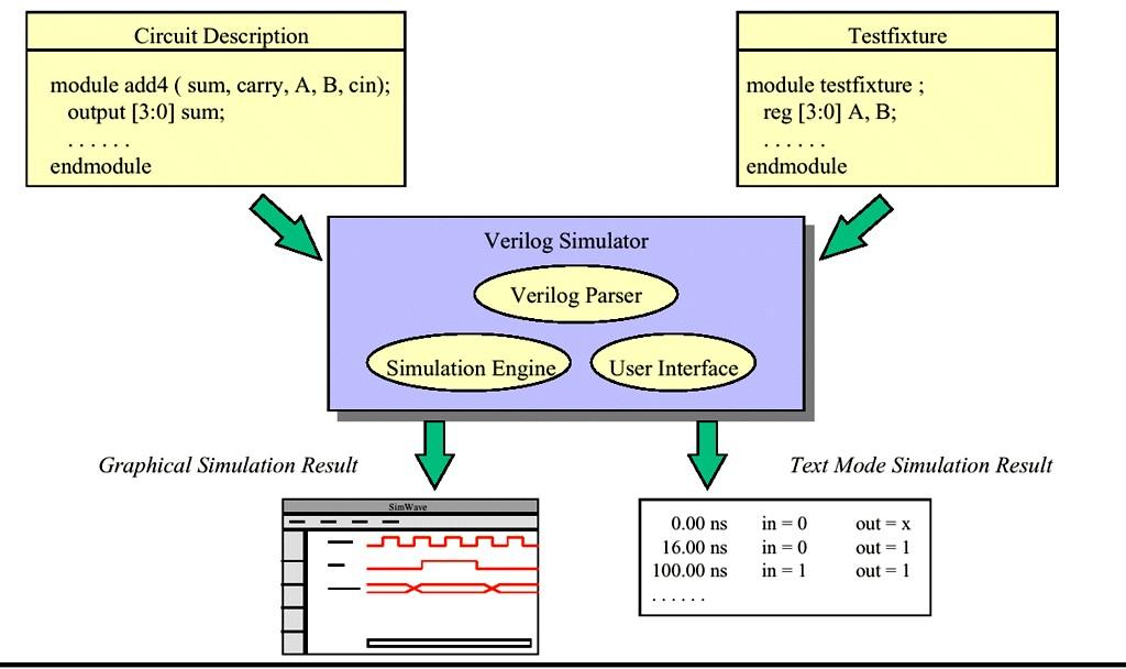
43 Verilog Simulator(1/2) P. 43
44 Verilog Simulator(2/2) Xilinx ISE Inventing the field programmable gate array (FPGA) Verilog Simulation Synthesis for FPGA ModelSim Verilog Simulation Only (But Powerful) P. 44
 P.")
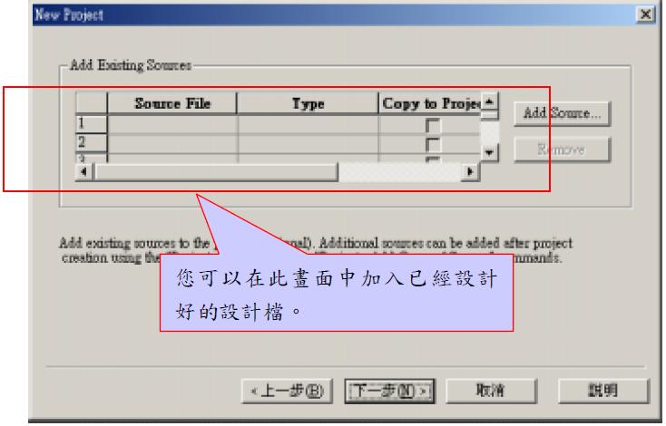
45 Xilinx ISE (1/5) Create a New Project File -> New Project Project Name & Location Type of top module (Can choose HDL) P. 45

46 Xilinx ISE (2/5) Next -> Project Wizard switches to the ``Device Properties'' window Your FPGA specification P. 46
")
47 Xilinx ISE (3/5) P. 47


48 Xilinx ISE (4/5) Project -> Add Source Double click Can modify your code P. 48

49 Xilinx ISE (5/5) Processes -> Xilinx ISE Simulator P. 49
 in library, you can see then by edit. P.")
50 ModelSim (1/8) There are some packages (for VHDL) in library, you can see then by edit. P. 50


51 ModelSim (2/8) File \ New \ Project... Insert the project name and location There are Viterbi.cr.mti Viterbi.mpf in the work forder.mpf include information of the project, so when you want to open the project, File \ Open \ Project... Open.mpf Add items to the project P. 51


52 ModelSim (3/8) Or use File \ Add to Project \ Existing Files... The direction path can not use Chiness. You can add and remove in work space. P. 52
")

53 ModelSim (4/8) Compile P. 53
 P.")
54 ModelSim (5/8) P. 54
")
 P.")
55 Simulate (Loading) ModelSim (6/8) P. 55
 Open")

56 ModelSim (7/8) Open signals window:view \ Signals P. 56
 Add to")

57 ModelSim (8/8) Add to Wave \ Selected Signals P. 57
101-1 Under-Graduate Project Digital IC Design Flow
 101-1 Under-Graduate Project Digital IC Design Flow Speaker: Ming-Chun Hsiao Adviser: Prof. An-Yeu Wu Date: 2012/9/25 ACCESS IC LAB Outline Introduction to Integrated Circuit IC Design Flow Verilog HDL
Verilog HDL Introduction
 EEE3050 Theory on Computer Architectures (Spring 2017) Prof. Jinkyu Jeong Verilog HDL Introduction 2017.05.14 TA 이규선 (GYUSUN LEE) / 안민우 (MINWOO AHN) Modules The Module Concept Basic design unit Modules
FPGA Design Challenge :Techkriti 14 Digital Design using Verilog Part 1
 FPGA Design Challenge :Techkriti 14 Digital Design using Verilog Part 1 Anurag Dwivedi Digital Design : Bottom Up Approach Basic Block - Gates Digital Design : Bottom Up Approach Gates -> Flip Flops Digital
Verilog Tutorial (Structure, Test)
") Digital Circuit Design and Language Verilog Tutorial (Structure, Test) Chang, Ik Joon Kyunghee University Hierarchical Design Top-down Design Methodology Bottom-up Design Methodology Module START Example)
Digital Circuit Design and Language Verilog Tutorial (Structure, Test) Chang, Ik Joon Kyunghee University Hierarchical Design Top-down Design Methodology Bottom-up Design Methodology Module START Example)
Graduate Institute of Electronics Engineering, NTU Basic Concept of HDL
 Basic Concept of HDL Lecturer: ( ) Date: 2004.03.05 ACCESS IC LAB Outline Hierarchical Design Methodology Basic Concept of Verilog HDL Switch Level Modeling Gate Level Modeling Simulation & Verification
CSE241 VLSI Digital Circuits Winter Recitation 1: RTL Coding in Verilog
 CSE241 VLSI Digital Circuits Winter 2003 Recitation 1: RTL Coding in Verilog CSE241 R1 Verilog.1 Kahng & Cichy, UCSD 2003 Topic Outline Introduction Verilog Background Connections Modules Procedures Structural
Verilog. What is Verilog? VHDL vs. Verilog. Hardware description language: Two major languages. Many EDA tools support HDL-based design
 Verilog What is Verilog? Hardware description language: Are used to describe digital system in text form Used for modeling, simulation, design Two major languages Verilog (IEEE 1364), latest version is
Contents. Appendix D Verilog Summary Page 1 of 16
 Appix D Verilog Summary Page 1 of 16 Contents Appix D Verilog Summary... 2 D.1 Basic Language Elements... 2 D.1.1 Keywords... 2 D.1.2 Comments... 2 D.1.3 Identifiers... 2 D.1.4 Numbers and Strings... 3
Lecturer: Chihhao Chao ( 趙之昊 ) Date:
 Date:") Basic Concept of Hardware Description Language Lecturer: ( 趙之昊 ) Date: 2009.02.25 The lecture note is based on Ch.4 of the textbook Review: Logic Design and Ch.2~Ch.3 of the textbook ACCESS IC LAB Overview
Basic Concept of Hardware Description Language Lecturer: ( 趙之昊 ) Date: 2009.02.25 The lecture note is based on Ch.4 of the textbook Review: Logic Design and Ch.2~Ch.3 of the textbook ACCESS IC LAB Overview
Introduction to Verilog
 Introduction to Verilog COE 202 Digital Logic Design Dr. Muhamed Mudawar King Fahd University of Petroleum and Minerals Presentation Outline Hardware Description Language Logic Simulation versus Synthesis
Online Verilog Resources
 EECS 427 Discussion 6: Verilog HDL Reading: Many references EECS 427 F08 Discussion 6 1 Online Verilog Resources ASICs the book, Ch. 11: http://www.ge.infn.it/~pratolo/verilog/verilogtutorial.pdf it/ pratolo/verilog/verilogtutorial
Schematic design. Gate level design. 0 EDA (Electronic Design Assistance) 0 Classical design. 0 Computer based language
 0 Classical design. 0 Computer based language") 1 / 15 2014/11/20 0 EDA (Electronic Design Assistance) 0 Computer based language 0 HDL (Hardware Description Language) 0 Verilog HDL 0 Created by Gateway Design Automation Corp. in 1983 First modern hardware
1 / 15 2014/11/20 0 EDA (Electronic Design Assistance) 0 Computer based language 0 HDL (Hardware Description Language) 0 Verilog HDL 0 Created by Gateway Design Automation Corp. in 1983 First modern hardware
Speaker: Kayting Adviser: Prof. An-Yeu Wu Date: 2009/11/23
 98-1 Under-Graduate Project Synthesis of Combinational Logic Speaker: Kayting Adviser: Prof. An-Yeu Wu Date: 2009/11/23 What is synthesis? Outline Behavior Description for Synthesis Write Efficient HDL
14:332:231 DIGITAL LOGIC DESIGN. Hardware Description Languages
 14:332:231 DIGITAL LOGIC DESIGN Ivan Marsic, Rutgers University Electrical & Computer Engineering Fall 2013 Lecture #22: Introduction to Verilog Hardware Description Languages Basic idea: Language constructs
Digital Design with FPGAs. By Neeraj Kulkarni
 Digital Design with FPGAs By Neeraj Kulkarni Some Basic Electronics Basic Elements: Gates: And, Or, Nor, Nand, Xor.. Memory elements: Flip Flops, Registers.. Techniques to design a circuit using basic
A Verilog Primer. An Overview of Verilog for Digital Design and Simulation
 A Verilog Primer An Overview of Verilog for Digital Design and Simulation John Wright Vighnesh Iyer Department of Electrical Engineering and Computer Sciences College of Engineering, University of California,
Introduction to Verilog HDL. Verilog 1
 Introduction to HDL Hardware Description Language (HDL) High-Level Programming Language Special constructs to model microelectronic circuits Describe the operation of a circuit at various levels of abstraction
Verilog Design Principles
 16 h7fex // 16-bit value, low order 4 bits unknown 8 bxx001100 // 8-bit value, most significant 2 bits unknown. 8 hzz // 8-bit value, all bits high impedance. Verilog Design Principles ECGR2181 Extra Notes
Chapter 2 Using Hardware Description Language Verilog. Overview
 Chapter 2 Using Hardware Description Language Verilog CSE4210 Winter 2012 Mokhtar Aboelaze based on slides by Dr. Shoab A. Khan Overview Algorithm development isa usually done in MATLAB, C, or C++ Code
Hardware Description Languages (HDLs) Verilog
 Verilog") Hardware Description Languages (HDLs) Verilog Material from Mano & Ciletti book By Kurtulus KULLU Ankara University What are HDLs? A Hardware Description Language resembles a programming language specifically
Hardware Description Languages (HDLs) Verilog Material from Mano & Ciletti book By Kurtulus KULLU Ankara University What are HDLs? A Hardware Description Language resembles a programming language specifically
EN2911X: Reconfigurable Computing Topic 02: Hardware Definition Languages
 EN2911X: Reconfigurable Computing Topic 02: Hardware Definition Languages Professor Sherief Reda http://scale.engin.brown.edu School of Engineering Brown University Spring 2014 1 Introduction to Verilog
Verilog Design Principles
 16 h7fex // 16-bit value, low order 4 bits unknown 8 bxx001100 // 8-bit value, most significant 2 bits unknown. 8 hzz // 8-bit value, all bits high impedance. Verilog Design Principles ECGR2181 Extra Notes
Advanced Digital Design with the Verilog HDL
 Copyright 2001, 2003 MD Ciletti 1 Advanced Digital Design with the Verilog HDL M. D. Ciletti Department of Electrical and Computer Engineering University of Colorado Colorado Springs, Colorado ciletti@vlsic.uccs.edu
Department of Computer Science and Electrical Engineering. Intro to Verilog II
 Department of Computer Science and Electrical Engineering Intro to Verilog II http://6004.csail.mit.edu/6.371/handouts/l0{2,3,4}.pdf http://www.asic-world.com/verilog/ http://www.verilogtutorial.info/
Design Using Verilog
 EGC220 Design Using Verilog Baback Izadi Division of Engineering Programs bai@engr.newpaltz.edu Basic Verilog Lexical Convention Lexical convention are close to C++. Comment // to the of the line. /* to
EECS 427 Lecture 14: Verilog HDL Reading: Many handouts/references. EECS 427 W07 Lecture 14 1
 EECS 427 Lecture 14: Verilog HDL Reading: Many handouts/references EECS 427 W07 Lecture 14 1 Online Verilog Resources ASICs the book, Ch. 11: http://www.ge.infn.it/~pratolo/verilog/verilogtutorial.pdf
Computer Aided Design Basic Syntax Gate Level Modeling Behavioral Modeling. Verilog
 Verilog Radek Pelánek and Šimon Řeřucha Contents 1 Computer Aided Design 2 Basic Syntax 3 Gate Level Modeling 4 Behavioral Modeling Computer Aided Design Hardware Description Languages (HDL) Verilog C
N-input EX-NOR gate. N-output inverter. N-input NOR gate
 Hardware Description Language HDL Introduction HDL is a hardware description language used to design and document electronic systems. HDL allows designers to design at various levels of abstraction. It
What is Verilog HDL? Lecture 1: Verilog HDL Introduction. Basic Design Methodology. What is VHDL? Requirements
 What is Verilog HDL? Lecture 1: Verilog HDL Introduction Verilog Hardware Description Language(HDL)? A high-level computer language can model, represent and simulate digital design Hardware concurrency
RIZALAFANDE CHE ISMAIL TKT. 3, BLOK A, PPK MIKRO-e KOMPLEKS PENGAJIAN KUKUM. SYNTHESIS OF COMBINATIONAL LOGIC (Chapter 8)
") RIZALAFANDE CHE ISMAIL TKT. 3, BLOK A, PPK MIKRO-e KOMPLEKS PENGAJIAN KUKUM SYNTHESIS OF COMBINATIONAL LOGIC (Chapter 8) HDL-BASED SYNTHESIS Modern ASIC design use HDL together with synthesis tool to create
RIZALAFANDE CHE ISMAIL TKT. 3, BLOK A, PPK MIKRO-e KOMPLEKS PENGAJIAN KUKUM SYNTHESIS OF COMBINATIONAL LOGIC (Chapter 8) HDL-BASED SYNTHESIS Modern ASIC design use HDL together with synthesis tool to create
Synthesizable Verilog
 Synthesizable Verilog Courtesy of Dr. Edwards@Columbia, and Dr. Franzon@NCSU http://csce.uark.edu +1 (479) 575-6043 yrpeng@uark.edu Design Methodology Structure and Function (Behavior) of a Design HDL
EECS150 - Digital Design Lecture 10 Logic Synthesis
 EECS150 - Digital Design Lecture 10 Logic Synthesis September 26, 2002 John Wawrzynek Fall 2002 EECS150 Lec10-synthesis Page 1 Logic Synthesis Verilog and VHDL stated out as simulation languages, but quickly
EECS150 - Digital Design Lecture 10 Logic Synthesis
 EECS150 - Digital Design Lecture 10 Logic Synthesis February 13, 2003 John Wawrzynek Spring 2003 EECS150 Lec8-synthesis Page 1 Logic Synthesis Verilog and VHDL started out as simulation languages, but
Hardware description languages
 Specifying digital circuits Schematics (what we ve done so far) Structural description Describe circuit as interconnected elements Build complex circuits using hierarchy Large circuits are unreadable Hardware
Introduction to Verilog/System Verilog
 NTUEE DCLAB Feb. 27, 2018 Introduction to Verilog/System Verilog Presenter: Yao-Pin Wang 王耀斌 Advisor: Prof. Chia-Hsiang Yang 楊家驤 Dept. of Electrical Engineering, NTU National Taiwan University What is
Lab #1. Topics. 3. Introduction to Verilog 2/8/ Programmable logic. 2. Design Flow. 3. Verilog --- A Hardware Description Language
 Lab #1 Lecture 8, 9, &10: FPGA Dataflow and Verilog Modeling February 9, 11, 13, 2015 Prof R Iris Bahar Lab #1 is posted on the webpage wwwbrownedu/departments/engineering/courses/engn1640 Note for problem
Hardware description language (HDL)
") Hardware description language (HDL) A hardware description language (HDL) is a computer-based language that describes the hardware of digital systems in a textual form. It resembles an ordinary computer
Hardware description language (HDL) A hardware description language (HDL) is a computer-based language that describes the hardware of digital systems in a textual form. It resembles an ordinary computer
Combinational Logic Design with Verilog. ECE 152A Winter 2012
 Combinational Logic Design with Verilog ECE 152A Winter 2012 Reading Assignment Brown and Vranesic 2 Introduction to Logic Circuits 2.10 Introduction to Verilog 2.10.1 Structural Specification of Logic
Verilog Fundamentals. Shubham Singh. Junior Undergrad. Electrical Engineering
 Verilog Fundamentals Shubham Singh Junior Undergrad. Electrical Engineering VERILOG FUNDAMENTALS HDLs HISTORY HOW FPGA & VERILOG ARE RELATED CODING IN VERILOG HDLs HISTORY HDL HARDWARE DESCRIPTION LANGUAGE
Verilog Design Entry, Synthesis, and Behavioral Simulation
 ------------------------------------------------------------- PURPOSE - This lab will present a brief overview of a typical design flow and then will start to walk you through some typical tasks and familiarize
Introduction To Verilog Design. Chun-Hung Chou
 Introduction To Verilog Design Chun-Hung Chou 1 Outline Typical Design Flow Design Method Lexical Convention Data Type Data Assignment Event Control Conditional Description Register Description Synthesizable
C-Based Hardware Design
 LECTURE 6 In this lecture we will introduce: The VHDL Language and its benefits. The VHDL entity Concurrent and Sequential constructs Structural design. Hierarchy Packages Various architectures Examples
ENGN1640: Design of Computing Systems Topic 02: Design/Lab Foundations
 ENGN1640: Design of Computing Systems Topic 02: Design/Lab Foundations Professor Sherief Reda http://scale.engin.brown.edu School of Engineering Brown University Spring 2017 1 Topics 1. Programmable logic
Graduate Institute of Electronics Engineering, NTU. Lecturer: Chihhao Chao Date:
 Synthesizable Coding of Verilog Lecturer: Date: 2009.03.18 ACCESS IC LAB Outline Basic concepts of logic synthesis Synthesizable Verilog coding subset Verilog coding practices Coding for readability Coding
Introduction to Verilog design. Design flow (from the book)
") Introduction to Verilog design Lecture 2 ECE 156A 1 Design flow (from the book) ECE 156A 2 1 Hierarchical Design Chip Modules Cells Primitives A chip contain many modules A module may contain other modules
Introduction to Verilog design Lecture 2 ECE 156A 1 Design flow (from the book) ECE 156A 2 1 Hierarchical Design Chip Modules Cells Primitives A chip contain many modules A module may contain other modules
This Lecture. Some components (useful for the homework) Verilog HDL (will continue next lecture)
 Verilog HDL (will continue next lecture)") Last Lecture The basic component of a digital circuit is the MOS transistor Transistor have instrinsic resistance and capacitance, so voltage values in the circuit take some time to change ( delay ) There
Last Lecture The basic component of a digital circuit is the MOS transistor Transistor have instrinsic resistance and capacitance, so voltage values in the circuit take some time to change ( delay ) There
Hardware Description Language VHDL (1) Introduction
 Introduction") Hardware Description Language VHDL (1) Introduction Digital Radiation Measurement and Spectroscopy NE/RHP 537 Introduction Hardware description language (HDL) Intended to describe circuits textually, for
Hardware Description Language VHDL (1) Introduction Digital Radiation Measurement and Spectroscopy NE/RHP 537 Introduction Hardware description language (HDL) Intended to describe circuits textually, for
Verilog HDL. A Guide to Digital Design and Synthesis. Samir Palnitkar. SunSoft Press A Prentice Hall Title
 Verilog HDL A Guide to Digital Design and Synthesis Samir Palnitkar SunSoft Press A Prentice Hall Title Table of Contents About the Author Foreword Preface Acknowledgments v xxxi xxxiii xxxvii Part 1:
Introduction to Verilog. Mitch Trope EECS 240 Spring 2004
 Introduction to Verilog Mitch Trope mtrope@ittc.ku.edu EECS 240 Spring 2004 Overview What is Verilog? Verilog History Max+Plus II Schematic entry Verilog entry System Design Using Verilog: Sum of Products
CSE140L: Components and Design Techniques for Digital Systems Lab
 CSE140L: Components and Design Techniques for Digital Systems Lab Tajana Simunic Rosing Source: Vahid, Katz, Culler 1 Announcements & Outline Lab 4 due; demo signup times listed on the cse140l site Check
A Brief Introduction to Verilog Hardware Definition Language (HDL)
") www.realdigital.org A Brief Introduction to Verilog Hardware Definition Language (HDL) Forward Verilog is a Hardware Description language (HDL) that is used to define the structure and/or behavior of digital
www.realdigital.org A Brief Introduction to Verilog Hardware Definition Language (HDL) Forward Verilog is a Hardware Description language (HDL) that is used to define the structure and/or behavior of digital
EEL 4783: HDL in Digital System Design
 EEL 4783: HDL in Digital System Design Lecture 15: Logic Synthesis with Verilog Prof. Mingjie Lin 1 Verilog Synthesis Synthesis vs. Compilation Descriptions mapped to hardware Verilog design patterns for
Spiral 1 / Unit 4 Verilog HDL. Digital Circuit Design Steps. Digital Circuit Design OVERVIEW. Mark Redekopp. Description. Verification.
 1-4.1 1-4.2 Spiral 1 / Unit 4 Verilog HDL Mark Redekopp OVERVIEW 1-4.3 1-4.4 Digital Circuit Design Steps Digital Circuit Design Description Design and computer-entry of circuit Verification Input Stimulus
FPGA: FIELD PROGRAMMABLE GATE ARRAY Verilog: a hardware description language. Reference: [1]
![FPGA: FIELD PROGRAMMABLE GATE ARRAY Verilog: a hardware description language. Reference: [1]](/thumbs/80/81661285.jpg "FPGA: FIELD PROGRAMMABLE GATE ARRAY Verilog: a hardware description language. Reference: [1]") FPGA: FIELD PROGRAMMABLE GATE ARRAY Verilog: a hardware description language Reference: [] FIELD PROGRAMMABLE GATE ARRAY FPGA is a hardware logic device that is programmable Logic functions may be programmed
FPGA: FIELD PROGRAMMABLE GATE ARRAY Verilog: a hardware description language Reference: [] FIELD PROGRAMMABLE GATE ARRAY FPGA is a hardware logic device that is programmable Logic functions may be programmed
CSE140L: Components and Design
 CSE140L: Components and Design Techniques for Digital Systems Lab Tajana Simunic Rosing Source: Vahid, Katz, Culler 1 Grade distribution: 70% Labs 35% Lab 4 30% Lab 3 20% Lab 2 15% Lab 1 30% Final exam
ENGN1640: Design of Computing Systems Topic 02: Design/Lab Foundations
 ENGN1640: Design of Computing Systems Topic 02: Design/Lab Foundations Professor Sherief Reda http://scale.engin.brown.edu School of Engineering Brown University Spring 2016 1 Topics 1. Programmable logic
CSE140L: Components and Design Techniques for Digital Systems Lab. Verilog HDL. Instructor: Mohsen Imani UC San Diego. Source: Eric Crabill, Xilinx
 CSE140L: Components and Design Techniques for Digital Systems Lab Verilog HDL Instructor: Mohsen Imani UC San Diego Source: Eric Crabill, Xilinx 1 Hardware description languages Used to describe & model
Abi Farsoni, Department of Nuclear Engineering and Radiation Health Physics, Oregon State University
 Hardware description language (HDL) Intended to describe circuits textually, for a computer to read Evolved starting in the 1970s and 1980s Popular languages today include: VHDL Defined in 1980s by U.S.
Introduction to Verilog design. Design flow (from the book) Hierarchical Design. Lecture 2
 Hierarchical Design. Lecture 2") Introduction to Verilog design Lecture 2 ECE 156A 1 Design flow (from the book) ECE 156A 2 Hierarchical Design Chip Modules Cells Primitives A chip contain many modules A module may contain other modules
Introduction to Verilog design Lecture 2 ECE 156A 1 Design flow (from the book) ECE 156A 2 Hierarchical Design Chip Modules Cells Primitives A chip contain many modules A module may contain other modules
Introduction to Verilog HDL
 Introduction to Verilog HDL Ben Abdallah Abderazek National University of Electro-communications, Tokyo, Graduate School of information Systems May 2004 04/09/08 1 What you will understand after having
Synthesis vs. Compilation Descriptions mapped to hardware Verilog design patterns for best synthesis. Spring 2007 Lec #8 -- HW Synthesis 1
 Verilog Synthesis Synthesis vs. Compilation Descriptions mapped to hardware Verilog design patterns for best synthesis Spring 2007 Lec #8 -- HW Synthesis 1 Logic Synthesis Verilog and VHDL started out
Advanced Digital Design Using FPGA. Dr. Shahrokh Abadi
 Advanced Digital Design Using FPGA Dr. Shahrokh Abadi 1 Venue Computer Lab: Tuesdays 10 12 am (Fixed) Computer Lab: Wednesday 10-12 am (Every other odd weeks) Note: Due to some unpredicted problems with
Digital Design Using VHDL Using Xilinx s Tool for Synthesis and ModelSim for Verification
 Digital Design Using VHDL Using Xilinx s Tool for Synthesis and ModelSim for Verification Ahmed Abu-Hajar, Ph.D. abuhajar@digitavid.net Digitavid, Inc San Jose, CA Session One Outline Introducing VHDL
Logic Synthesis. EECS150 - Digital Design Lecture 6 - Synthesis
 Logic Synthesis Verilog and VHDL started out as simulation languages, but quickly people wrote programs to automatically convert Verilog code into low-level circuit descriptions (netlists). EECS150 - Digital
Verilog. Like VHDL, Verilog HDL is like a programming language but:
 Verilog Verilog Like VHDL, Verilog HDL is like a programming language but: Statements can execute simultaneously unlike programming e.g. nand(y1,a1,b1); nand(y2,a2,b2); or (out,y1,y2); a1 b1 all statements
EGC220 - Digital Logic Fundamentals
 EGC220 - Digital Logic Fundamentals VERILOG Hardware Description Language - 1 Hardware description language is a text based programming language that is used to model a piece of hardware. VERILOG is a
Combinational Logic II
 Combinational Logic II Ranga Rodrigo July 26, 2009 1 Binary Adder-Subtractor Digital computers perform variety of information processing tasks. Among the functions encountered are the various arithmetic
Lab 7 (All Sections) Prelab: Introduction to Verilog
 Prelab: Introduction to Verilog") Lab 7 (All Sections) Prelab: Introduction to Verilog Name: Sign the following statement: On my honor, as an Aggie, I have neither given nor received unauthorized aid on this academic work 1 Objective The
Lab 7 (All Sections) Prelab: Introduction to Verilog Name: Sign the following statement: On my honor, as an Aggie, I have neither given nor received unauthorized aid on this academic work 1 Objective The
ECE 353 Lab 4. Verilog Review. Professor Daniel Holcomb With material by Professor Moritz and Kundu UMass Amherst Fall 2016
 ECE 353 Lab 4 Verilog Review Professor Daniel Holcomb With material by Professor Moritz and Kundu UMass Amherst Fall 2016 Recall What You Will Do Design and implement a serial MIDI receiver Hardware in
ENGN1640: Design of Computing Systems Topic 02: Lab Foundations
 ENGN1640: Design of Computing Systems Topic 02: Lab Foundations Professor Sherief Reda http://scale.engin.brown.edu School of Engineering Brown University Spring 2014 1 Topics 1. Programmable logic 2.
Lecture 15: System Modeling and Verilog
 Lecture 15: System Modeling and Verilog Slides courtesy of Deming Chen Intro. VLSI System Design Outline Outline Modeling Digital Systems Introduction to Verilog HDL Use of Verilog HDL in Synthesis Reading
Chap 3. Modeling structure & basic concept of Verilog HDL
 Chap 3. Modeling structure & basic concept of Verilog HDL Fall semester, 2016 Prof. Jaeseok Kim School of Electrical & Electronics Eng. Yonsei university jaekim@yonsei.ac.kr Digital System Design 3-1 Chapter
Synthesis of Combinational and Sequential Circuits with Verilog
 Synthesis of Combinational and Sequential Circuits with Verilog What is Verilog? Hardware description language: Are used to describe digital system in text form Used for modeling, simulation, design Two
Verilog introduction. Embedded and Ambient Systems Lab
 Verilog introduction Embedded and Ambient Systems Lab Purpose of HDL languages Modeling hardware behavior Large part of these languages can only be used for simulation, not for hardware generation (synthesis)
ECEN 468 Advanced Digital System Design
 ECEN 468 Advanced Digital System Design Lecture 19: Logic Design with Verilog Verilog Module v Description of internal structure/function o Implicit semantic of time associated with each data object/ signal
Module 4. Design of Embedded Processors. Version 2 EE IIT, Kharagpur 1
 Module 4 Design of Embedded Processors Version 2 EE IIT, Kharagpur 1 Lesson 23 Introduction to Hardware Description Languages-III Version 2 EE IIT, Kharagpur 2 Instructional Objectives At the end of the
ECE 353 Lab 3 (Verilog Design Approach)
") ECE 353 Lab 3 (Verilog Design Approach) Prof Daniel Holcomb Recall What You Will Do Design and implement a serial MIDI receiver Hardware in an Altera Complex Programmable Logic Device (CPLD) MAX 7000S
ECE 353 Lab 3 (Verilog Design Approach) Prof Daniel Holcomb Recall What You Will Do Design and implement a serial MIDI receiver Hardware in an Altera Complex Programmable Logic Device (CPLD) MAX 7000S
Chapter 2a: Structural Modeling
 Chapter 2a: Structural Modeling Prof. Ming-Bo Lin Department of Electronic Engineering National Taiwan University of Science and Technology Digital System Designs and Practices Using Verilog HDL and FPGAs
VHDL for Synthesis. Course Description. Course Duration. Goals
 VHDL for Synthesis Course Description This course provides all necessary theoretical and practical know how to write an efficient synthesizable HDL code through VHDL standard language. The course goes
Lab 7 (Sections 300, 301 and 302) Prelab: Introduction to Verilog
 Prelab: Introduction to Verilog") Lab 7 (Sections 300, 301 and 302) Prelab: Introduction to Verilog Name: Sign the following statement: On my honor, as an Aggie, I have neither given nor received unauthorized aid on this academic work
Lab 7 (Sections 300, 301 and 302) Prelab: Introduction to Verilog Name: Sign the following statement: On my honor, as an Aggie, I have neither given nor received unauthorized aid on this academic work
CSE 591: Advanced Hardware Design and Verification (2012 Spring) LAB #0
 LAB #0") Lab 0: Tutorial on Xilinx Project Navigator & ALDEC s Active-HDL Simulator CSE 591: Advanced Hardware Design and Verification Assigned: 01/05/2011 Due: 01/19/2011 Table of Contents 1 Overview... 2 1.1
Lab 0: Tutorial on Xilinx Project Navigator & ALDEC s Active-HDL Simulator CSE 591: Advanced Hardware Design and Verification Assigned: 01/05/2011 Due: 01/19/2011 Table of Contents 1 Overview... 2 1.1
structure syntax different levels of abstraction
 This and the next lectures are about Verilog HDL, which, together with another language VHDL, are the most popular hardware languages used in industry. Verilog is only a tool; this course is about digital
Here is a list of lecture objectives. They are provided for you to reflect on what you are supposed to learn, rather than an introduction to this
 This and the next lectures are about Verilog HDL, which, together with another language VHDL, are the most popular hardware languages used in industry. Verilog is only a tool; this course is about digital
Verilog 1 - Fundamentals
 Verilog 1 - Fundamentals FA FA FA FA module adder( input [3:0] A, B, output cout, output [3:0] S ); wire c0, c1, c2; FA fa0( A[0], B[0], 1 b0, c0, S[0] ); FA fa1( A[1], B[1], c0, c1, S[1] ); FA fa2( A[2],
The Verilog Language COMS W Prof. Stephen A. Edwards Fall 2002 Columbia University Department of Computer Science
 The Verilog Language COMS W4995-02 Prof. Stephen A. Edwards Fall 2002 Columbia University Department of Computer Science The Verilog Language Originally a modeling language for a very efficient event-driven
Chap 6 Introduction to HDL (d)
") Design with Verilog Chap 6 Introduction to HDL (d) Credit to: MD Rizal Othman Faculty of Electrical & Electronics Engineering Universiti Malaysia Pahang Ext: 6036 VERILOG HDL Basic Unit A module Module
Design with Verilog Chap 6 Introduction to HDL (d) Credit to: MD Rizal Othman Faculty of Electrical & Electronics Engineering Universiti Malaysia Pahang Ext: 6036 VERILOG HDL Basic Unit A module Module
Tutorial on Verilog HDL
 Tutorial on Verilog HDL HDL Hardware Description Languages Widely used in logic design Verilog and VHDL Describe hardware using code Document logic functions Simulate logic before building Synthesize code
EE 8351 Digital Logic Circuits Ms.J.Jayaudhaya, ASP/EEE
 EE 8351 Digital Logic Circuits Ms.J.Jayaudhaya, ASP/EEE 1 Logic circuits for digital systems may be combinational or sequential. A combinational circuit consists of input variables, logic gates, and output
Verilog Hardware Description Language ROOM: B405
 Verilog Hardware Description Language HONG@IS.NAIST.JP ROOM: B405 Content Lecture 1: Computer organization and performance evaluation metrics Lecture 2: Processor architecture and memory system Lecture
ECE U530 Digital Hardware Synthesis. Course Accounts and Tools
 ECE U530 Digital Hardware Synthesis Prof. Miriam Leeser mel@coe.neu.edu Sept 13, 2006 Lecture 3: Basic VHDL constructs Signals, Variables, Constants VHDL Simulator and Test benches Types Reading: Ashenden
Synthesis of Language Constructs. 5/10/04 & 5/13/04 Hardware Description Languages and Synthesis
 Synthesis of Language Constructs 1 Nets Nets declared to be input or output ports are retained Internal nets may be eliminated due to logic optimization User may force a net to exist trireg, tri0, tri1
Lecture 2: Data Types, Modeling Combinational Logic in Verilog HDL. Variables and Logic Value Set. Data Types. Why use an HDL?
 Why use an HDL? Lecture 2: Data Types, Modeling Combinational Logic in Verilog HDL Increase digital design engineer s productivity (from Dataquest) Behavioral HDL RTL HDL Gates Transistors 2K 10K gates/week
Under-Graduate Project Logic Design with Behavioral Models
 97-1 1 Under-Graduate Project Logic Design with Behavioral Models Speaker: 吳佳謙 Adviser: Prof. An-Yeu Wu Date: 2008/10/20 ACCESS IC LAB Operation Assignment Outline Blocking and non-blocking Appendix pp.
Image Courtesy CS250 Section 2. Yunsup Lee 9/4/09
 CS250 Section 2 Image Courtesy www.intel.com Yunsup Lee 9/4/09 Upcoming dates! 9/8/09 (12:30pm) - Lab 1 due (No late days for Lab 1!)! Submit using SVN (source, build, writeup)! 9/8/09 - Lab 2 out! Write
UNIT V: SPECIFICATION USING VERILOG HDL
 UNIT V: SPECIFICATION USING VERILOG HDL PART -A (2 Marks) 1. What are identifiers? Identifiers are names of modules, variables and other objects that we can reference in the design. Identifiers consists
Introduction. Why Use HDL? Simulation output. Explanation
 Introduction Verilog HDL is a Hardware Description Language (HDL) HDL is a language used to describe a digital system, for example, a computer or a component of a computer. Most popular HDLs are VHDL and
Lecture 3: Modeling in VHDL. EE 3610 Digital Systems
 EE 3610: Digital Systems 1 Lecture 3: Modeling in VHDL VHDL: Overview 2 VHDL VHSIC Hardware Description Language VHSIC=Very High Speed Integrated Circuit Programming language for modelling of hardware
DIGITAL SYSTEM DESIGN
 DIGITAL SYSTEM DESIGN Prepared By: Engr. Yousaf Hameed Lab Engineer BASIC ELECTRICAL & DIGITAL SYSTEMS LAB DEPARTMENT OF ELECTRICAL ENGINEERING Digital System Design 1 Name: Registration No: Roll No: Semester:
Combinational Logic. Prof. Wangrok Oh. Dept. of Information Communications Eng. Chungnam National University. Prof. Wangrok Oh(CNU) 1 / 93
 1 / 93") Combinational Logic Prof. Wangrok Oh Dept. of Information Communications Eng. Chungnam National University Prof. Wangrok Oh(CNU) / 93 Overview Introduction 2 Combinational Circuits 3 Analysis Procedure
Combinational Logic Prof. Wangrok Oh Dept. of Information Communications Eng. Chungnam National University Prof. Wangrok Oh(CNU) / 93 Overview Introduction 2 Combinational Circuits 3 Analysis Procedure
Verilog 1 - Fundamentals
 Verilog 1 - Fundamentals FA FA FA FA module adder( input [3:0] A, B, output cout, output [3:0] S ); wire c0, c1, c2; FA fa0( A[0], B[0], 1 b0, c0, S[0] ); FA fa1( A[1], B[1], c0, c1, S[1] ); FA fa2( A[2],