CHAPTER ASSEMBLY LANGUAGE PROGRAMMING
|
|
|
- Sybil Perkins
- 6 years ago
- Views:
Transcription

1 CHAPTER ASSEMBLY LANGUAGE PROGRAMMING
2 Registers Register are used to store information temporarily: A byte of data to be processed An address pointing to the data to be fetched The vast majority of 8051 register are 8- bit registers There is only one data type, 8 bits The 8 bits of a register are labeled from MSB D7 to the LSB D0
 Any data larger than 8 bits must be broken into")
3 Registers (cont.) Any data larger than 8 bits must be broken into 8-bit chunks before it is processed
4 Registers (cont.) The most widely used registers: A (Accumulator) For all arithmetic and logic instructions B, R0, R1, R2, R3, R4, R5, R6, R7 DPTR (data pointer) PC (program counter)
5 Registers (cont.)
6 MOV Instruction MOV destination, source ;copy source to dest. The instruction tells the CPU to move (in reality, COPY) the source operand to the destination operand
 Notes on programming Value (proceeded with #) can be")
7 MOV Instruction (cont.) Notes on programming Value (proceeded with #) can be loaded directly to registers A, B, or R0 R7
8 MOV Instruction (cont.) If #23H is not preceded with #, it means to load from a memory location For #0F9H, add a 0 to indicate F is a hex number and not a letter If values 0 to F moved into an 8-bit register, the rest of the bits are assumed all zeros MOV A, #5, the result will be A=05 i.e., A = in binary Moving a value that is too large into a register will cause an error MOV A, #7F2H ILLEGAL: 7F2H > 8 bits (FFH)
9 ADD Instruction ADD A, source ;ADD the source operand to the accumulator The ADD instruction tells the CPU to add the source byte to register A and put the result in register A Source operand can be either a register or immediate data, but the destination must always be register A ADD R4, A and ADD R2, #12H are invalid since A must be the destination of any arithmetic operation
10 ADD Instruction (cont.)
11 Structure of Assembly Language In the early days of the computer, programmers coded in machine language Consisting of 0s and 1s Tedious, slow and prone to error Assembly languages provide mnemonics for the machine code instructions, plus other features An Assembly language program consist of a series of lines of Assembly language instructions
12 Structure of Assembly Language (cont.) Assembly language is referred to as a lowlevel language It deals directly with the internal structure of the CPU Assembly language instruction includes: A mnemonic (abbreviation easy to remember) The commands to the CPU, telling it what those to do with those items Optionally followed by one or two operands The data items being manipulated
13 Structure of Assembly Language (cont.) A given Assembly language program is a series of statements, or lines Assembly language instructions Tell the CPU what to do Directives (or pseudo-instructions) Give directions to the assembler An Assembly language instruction consists of four fields: [label:] Mnemonic [operands] [;comment]
14 Structure of Assembly Language (cont.) Directives do not generate any machine code and are used only by the assembler Mnemonics produce opcodes The label field allows the program to refer to a line of code by name Comments may be at the end of a line or on a line by themselves The assembler ignores comments
15 Structure of Assembly Language (cont.)
16 Steps to Create a Program
17 abs and hex Files The linker program takes one or more object code files and produce an absolute object file With the extension abs This abs file is used by 8051 trainers that have a monitor program Next the abs file is fed into a program called OH (object to hex converter) Creating a file with extension hex that is ready to burn into ROM
18 lst File The lst (list) file lists all the opcodes and addresses as well as errors that the assembler detected The programmer uses the lst file to find the syntax errors or debug
19 Program Counter The program counter points to the address of the next instruction to be executed As the CPU fetches the opcode from the program ROM, the program counter is increasing to point to the next instruction The program counter is 16 bits wide This means that it can access program addresses 0000 to FFFFH A total of 64K bytes of code

20 Power up All 8051 members start at memory address 0000 when they re powered up Program Counter has the value of 0000 The first opcode is burned into ROM address 0000H This is where the 8051 looks for the first instruction when it is booted We achieve this by the ORG statement in the source program
21 Placing Code in ROM
22 Placing Code in ROM (cont.) After the program is burned into ROM, the opcode and operand are placed in ROM memory location starting at 0000
23 Executing a program byte by byte Assuming that the above program is burned into the ROM of an 8051 chip (or 8751, AT8951, or DS5000), the following is a step-by-step description of the action of the 8051 upon applying power to it. 1. When the 8051 is powered up, the PC (program counter) has 0000 and starts to fetch the first opcode from location 0000 of the program ROM. 2. Upon executing the opcode 7F, the value 34H is moved into R7. Then the program counter is incremented to 0004.

24 3.ROM location 0004 has the opcode for the instruction MOV A,#0. This instruction is executed and now PC = Now PC = 0006 points to the next instruction, which is ADD A,R5. This is a 1-byte instruction. 5.The location 0007 has the opcode 2F, which belongs to the instruction ADD A,R7. This also is a 1-byte instruction.

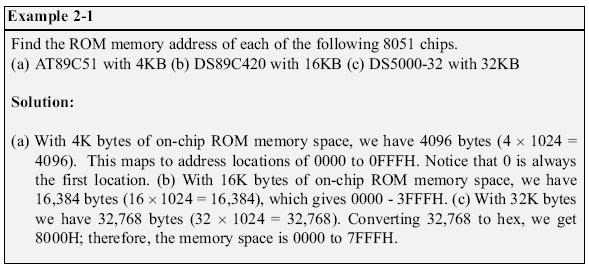
25 ROM Memory Map in 8051 Family No member of 8051 family can access more than 64K bytes of opcode The program counter is a 16-bit register
26
27 Data Type 8051 microcontroller has only one data type - 8 bits The size of each register is also 8 bits It is the job of the programmer to break down data larger than 8 bits 00 to FFH, or 0 to 255 in decimal The data types can be positive or negative
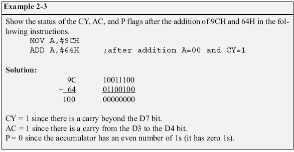
28 Program Status Word The program status word (PSW) register is an 8 bit register Also referred to as the flag register Only 6 bits are used These four are called conditional flags They indicate some conditions that resulted after an instruction was executed CY (carry): Carry out from the D7 bit AC (auxiliary carry): A carry from D3 to D4 P (parity): Reflect the number of 1s in register A
29 Program Status Word (cont.) OV (overflow): The result of signed number operation is too large, causing the high-order bit to overflow into the sign bit The PSW3 and PSW4 are designed as RS0 and RS1 Used to change the bank The two unused bits are user-definable
30
31
32 The flag bits affected by the ADD instruction are CY, P, AC, and OV
33

34
35 RAM Memory Space Allocation There are 128 bytes of RAM in the 8051 Assigned addresses 00 to 7FH Divided into three different groups as follows: 1) A total of 32 bytes from locations 00 to 1F hex are set aside for register banks and the stack 2) A total of 16 bytes from locations 20H to 2FH are set aside for bit-addressable read/write memory 3) A total of 80 bytes from locations 30H to 7FH are used for read and write storage Called scratch pad

36 RAM Memory Space Allocation (cont.)
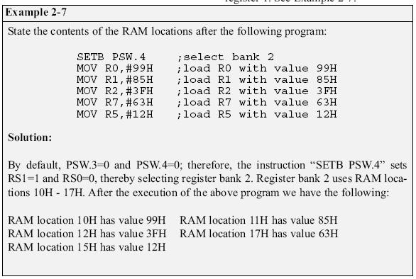
37 Register Banks These 32 bytes are divided into 4 banks of registers Each bank has 8 registers, R0-R7 RAM location from 0 to 7 are set aside for bank 0 of R0-R7 R0 is RAM location 0, R1 is RAM location 1, R2 is RAM location 2, and so on, until memory location 7 which belongs to R7 of bank 0 It is much easier to refer to these RAM locations with names such as R0, R1, and so on, than by their memory locations
38 Register Banks (cont.) Register bank 0 is the default when 8051 is powered up Register banks and their RAM address
39 Register Banks (cont.) We can switch to other banks by use of the PSW register Bits D4 and D3 of the PSW are used to select the desired register bank Use the bit-addressable instructions SETB and CLR to access PSW.4 and PSW.3
40
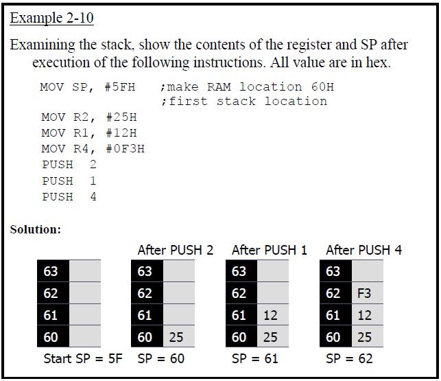
41 Stack The stack is a section of RAM used by the CPU to store information temporarily This information could be data or an address The register used to access the stack is called the SP (stack pointer) register The stack pointer in the 8051 is 8 bit wide It can only take value of 00 to FFH When the 8051 is powered up, the SP register contains value 07
42 Stack (cont.) RAM location 08 is the first location begin used for the stack by the 8051 The storing of a CPU register in the stack is called a PUSH SP is pointing to the last used location of the stack As we push data onto the stack, the SP is incremented by one This is different from many microprocessors
43 Stack (cont.) Loading the contents of the stack back into a CPU register is called a POP With every pop, the top byte of the stack is copied to the register specified by the instruction The stack pointer is decremented once
44
45
46 CALL Instruction And Stack The CPU also uses the stack to save the address of the instruction just below the CALL instruction This is how the CPU knows where to resume when it returns from the called subroutine
47 Incrementing Stack Pointer The reason of incrementing SP after push: Make sure that the stack is growing toward RAM location 7FH From lower to upper addresses Ensure that the stack will not reach the bottom of RAM and run out of stack space If the stack pointer were decremented after push We would be using RAM locations 7, 6, 5, etc. which belong to R7 to R0 of bank 0, the default register bank
48 Stack and Bank 1 Conflict When 8051 is powered up, register bank 1 and the stack are using the same memory space Because locations 08-1FH of RAM are reserved for register bank 1 We can reallocate another section of RAM to the stack By using the instruction MOV SP, #XX
49
ELEG3924 Microprocessor
 Department of Electrical Engineering University of Arkansas ELEG3924 Microprocessor Ch.2 Assembly Language Programming Dr. Jing Yang jingyang@uark.edu 1 OUTLINE Inside 8051 Introduction to assembly programming
ELEG3923 Microprocessor Ch.2 Assembly Language Programming
 Department of Electrical Engineering University of Arkansas ELEG3923 Microprocessor Ch.2 Assembly Language Programming Dr. Jingxian Wu wuj@uark.edu OUTLINE 2 Inside 8051 Introduction to assembly programming
8051 Microcontrollers
 8051 Microcontrollers Richa Upadhyay Prabhu NMIMS s MPSTME richa.upadhyay@nmims.edu March 8, 2016 Controller vs Processor Controller vs Processor Introduction to 8051 Micro-controller In 1981,Intel corporation
The 8051 Microcontroller and Embedded Systems
 The 8051 Microcontroller and Embedded Systems CHAPTER 2 8051 ASSEMBLY LANGUAGE PROGRAMMING OBJECTIVES List the registers of the 8051 microcontroller Manipulate data using the registers and MOV instructions
8051 Overview and Instruction Set
 8051 Overview and Instruction Set Curtis A. Nelson Engr 355 1 Microprocessors vs. Microcontrollers Microprocessors are single-chip CPUs used in microcomputers Microcontrollers and microprocessors are different
Assembly Language programming (1)
") EEE3410 Microcontroller Applications LABORATORY Experiment 1 Assembly Language programming (1) Name Class Date Class No. Marks Familiarisation and use of 8051 Simulation software Objectives To learn how
EEE3410 Microcontroller Applications LABORATORY Experiment 1 Assembly Language programming (1) Name Class Date Class No. Marks Familiarisation and use of 8051 Simulation software Objectives To learn how
8051 Microcontroller
 8051 Microcontroller EE4380 Fall 2001 Pari vallal Kannan Center for Integrated Circuits and Systems University of Texas at Dallas 8051 Architecture Programmer s View Register Set Instruction Set Memory
 Contents 8051 Instruction Set BY D. BALAKRISHNA, Research Assistant, IIIT-H Chapter I : Control Transfer Instructions Lesson (a): Loop Lesson (b): Jump (i) Conditional Lesson (c): Lesson (d): Lesson (e):
EEE3410 Microcontroller Applications Department of Electrical Engineering Lecture 4 The 8051 Architecture
 Department of Electrical Engineering Lecture 4 The 8051 Architecture 1 In this Lecture Overview General physical & operational features Block diagram Pin assignments Logic symbol Hardware description Pin
The Microcontroller. Lecture Set 3. Major Microcontroller Families. Example Microcontroller Families Cont. Example Microcontroller Families
 The Microcontroller Lecture Set 3 Architecture of the 8051 Microcontroller Microcontrollers can be considered as self-contained systems with a processor, memory and I/O ports. In most cases, all that is
Microcontroller Intel [Instruction Set]
![Microcontroller Intel [Instruction Set]](/thumbs/82/86620819.jpg "Microcontroller Intel [Instruction Set]") Microcontroller Intel 8051 [Instruction Set] Structure of Assembly Language [ label: ] mnemonic [operands] [ ;comment ] Example: MOV R1, #25H ; load data 25H into R1 2 8051 Assembly Language Registers
Microcontroller Intel 8051 [Instruction Set] Structure of Assembly Language [ label: ] mnemonic [operands] [ ;comment ] Example: MOV R1, #25H ; load data 25H into R1 2 8051 Assembly Language Registers
Memory organization Programming model - Program status word - register banks - Addressing modes - instruction set Programming examples.
 MICROCONTROLLERS AND APPLICATIONS 1 Module 2 Module-2 Contents: Memory organization Programming model - Program status word - register banks - Addressing modes - instruction set Programming examples. MEMORY
Figure Programming model
 LAB 1: Intel 8051 CPU PROGRAMMING DATA TRANSFER INSTRUCTIONS OBJECTIVES At the end of the laboratory works, you should be able to write simple assembly language programs for the Intel 8051 CPU using data
CC411: Introduction To Microprocessors
 CC411: Introduction To Microprocessors OBJECTIVES this chapter enables the student to: Describe the Intel family of microprocessors from 8085 to Pentium. In terms of bus size, physical memory & special
Principle and Interface Techniques of Microcontroller
 Principle and Interface Techniques of Microcontroller --8051 Microcontroller and Embedded Systems Using Assembly and C LI, Guang ( 李光 ) Prof. PhD, DIC, MIET WANG, You ( 王酉 ) PhD, MIET 杭州 浙江大学 2014 Chapter
UNIT-III ASSEMBLY LANGUAGE PROGRAMMING. The CPU can access data in various ways, which are called addressing modes
 8051 Software Overview: 1. Addressing Modes 2. Instruction Set 3. Programming 8051 Addressing Modes: UNIT-III ASSEMBLY LANGUAGE PROGRAMMING The CPU can access data in various ways, which are called addressing
8051 Microcontrollers
 8051 Microcontrollers Richa Upadhyay Prabhu NMIMS s MPSTME richa.upadhyay@nmims.edu March 15, 2016 8051 INSTRUCTIONS JUMP, LOOP AND CALL INSTRUCTIONS 8051 INSTRUCTIONS Repeating a sequence of instructions
Module Contents of the Module Hours COs
 Microcontrollers (EE45): Syllabus: Module Contents of the Module Hours COs 1 8051 MICROCONTROLLER ARCHITECTURE: Introduction to Microprocessors and Microcontrollers, the 8051 Architecture, 08 1 and pin
8051 Programming using Assembly
 8051 Programming using Assembly The Instruction Addressing Modes dest,source ; dest = source A,#72H ;A=72H A, # r ;A= r OR 72H R4,#62H ;R4=62H B,0F9H ;B=the content of F9 th byte of RAM DPTR,#7634H DPL,#34H
Lecture 5. EEE3410 Microcontroller Applications Department of Electrical Engineering Assembly Language Programming (1)
") Department of Electrical Engineering Lecture 5 8051 Assembly Language Programming (1) 1 In this Lecture 8051 programming model Assembly language syntax Operation codes and operands Machine instructions
Department of Electrical Engineering Lecture 5 8051 Assembly Language Programming (1) 1 In this Lecture 8051 programming model Assembly language syntax Operation codes and operands Machine instructions
ORG ; TWO. Assembly Language Programming
 Dec 2 Hex 2 Bin 00000010 ORG ; TWO Assembly Language Programming OBJECTIVES this chapter enables the student to: Explain the difference between Assembly language instructions and pseudo-instructions. Identify
EXPERIMENT NO. 1 THE MKT 8085 MICROPROCESSOR TRAINER
 OBJECT: EXPERIMENT NO. 1 THE MKT 8085 MICROPROCESSOR TRAINER To understand the structure and operating instruction of the microprocessor trainer. INTRODUCTION: The MKT 8085 is a single-board microcomputer,
ENE 334 Microprocessors
 Page 1 ENE 334 Microprocessors Lecture 9: MCS-51: Moving Data : Dejwoot KHAWPARISUTH http://webstaff.kmutt.ac.th/~dejwoot.kha/ ENE 334 MCS-51 Moving Data Page 2 Moving Data: Objectives Use commands that
VARDHAMAN COLLEGE OF ENGINEERING (AUTONOMOUS) Shamshabad, Hyderabad
 Shamshabad, Hyderabad") Introduction to MS-DOS Debugger DEBUG In this laboratory, we will use DEBUG program and learn how to: 1. Examine and modify the contents of the 8086 s internal registers, and dedicated parts of the memory
Introduction to MS-DOS Debugger DEBUG In this laboratory, we will use DEBUG program and learn how to: 1. Examine and modify the contents of the 8086 s internal registers, and dedicated parts of the memory
 8051 Memory Organization BY D. BALAKRISHNA, Research Assistant, IIIT-H Chapter 1: Memory Organization There are 2 types of memories available in 8051 microcontroller. Program memory/c code memory (ROM)
8051 microcontrollers
 8051 microcontrollers Presented by: Deepak Kumar Rout Synergy Institute of Engineering and Technology, Dhenkanal Chapter 2 Introduction Intel MCS-51 family of microcontrollers consists of various devices
Instruction : A command to the microprocessor to perform a given task on specified data. Each instruction has two parts
 Lecture 4 Instruction : A command to the microprocessor to perform a given task on specified data. Each instruction has two parts One part is the task to be performed, called operation code or opcode in
Assembly Language programming (2)
") EEE3410 Microcontroller Applications LABORATORY Experiment 2 Assembly Language programming (2) Name Class Date Class No. Marks Arithmetic, Logic and Jump instructions Objectives To learn and practice the
EEE3410 Microcontroller Applications LABORATORY Experiment 2 Assembly Language programming (2) Name Class Date Class No. Marks Arithmetic, Logic and Jump instructions Objectives To learn and practice the
SN8F5000 Family Instruction Set
 SONiX Technology Co., Ltd. 8051-based Microcontroller 1 Overview SN8F5000 is 8051 Flash Type microcontroller supports comprehensive assembly instructions and which are fully compatible with standard 8051.
ENE 334 Microprocessors
 Page 1 ENE 334 Microprocessors Lecture 10: MCS-51: Logical and Arithmetic : Dejwoot KHAWPARISUTH http://webstaff.kmutt.ac.th/~dejwoot.kha/ ENE 334 MCS-51 Logical & Arithmetic Page 2 Logical: Objectives
ET2640 Microprocessors
 ET2640 Microprocessors Unit -2 Processor Programming Concepts Basic Control Instructor : Stan Kong Email : skong@itt-tech.edu Figure 2 4 Bits of the PSW Register 8051 REGISTER BANKS AND STACK 80 BYTES
8051 Microcontroller
 8051 Microcontroller 1 Salient Features (1). 8 bit microcontroller originally developed by Intel in 1980. (2). High-performance CMOS Technology. (3). Contains Total 40 pins. (4). Address bus is of 16 bit
Microcomputer Architecture and Programming
 IUST-EE (Chapter 1) Microcomputer Architecture and Programming 1 Outline Basic Blocks of Microcomputer Typical Microcomputer Architecture The Single-Chip Microprocessor Microprocessor vs. Microcontroller
Principle and Interface Techniques of Microcontroller
 Principle and Interface Techniques of Microcontroller --8051 Microcontroller and Embedded Systems Using Assembly and C LI, Guang ( 李光 ) Prof. PhD, DIC, MIET WANG, You ( 王酉 ) PhD, MIET 杭州 浙江大学 2011 Chapter
Architecture & Instruction set of 8085 Microprocessor and 8051 Micro Controller
 of 8085 microprocessor 8085 is pronounced as "eighty-eighty-five" microprocessor. It is an 8-bit microprocessor designed by Intel in 1977 using NMOS technology. It has the following configuration 8-bit
1. INTRODUCTION TO MICROPROCESSOR AND MICROCOMPUTER ARCHITECTURE:
 1. INTRODUCTION TO MICROPROCESSOR AND MICROCOMPUTER ARCHITECTURE: A microprocessor is a programmable electronics chip that has computing and decision making capabilities similar to central processing unit
Microprocessors 1. The 8051 Instruction Set. Microprocessors 1 1. Msc. Ivan A. Escobar Broitman
 Microprocessors 1 The 8051 Instruction Set Microprocessors 1 1 Instruction Groups The 8051 has 255 instructions Every 8-bit opcode from 00 to FF is used except for A5. The instructions are grouped into
Assembly Language Programming of 8085
 Assembly Language Programming of 8085 Topics 1. Introduction 2. Programming model of 8085 3. Instruction set of 8085 4. Example Programs 5. Addressing modes of 8085 6. Instruction & Data Formats of 8085
Assembly Language Programming
 Experiment 3 Assembly Language Programming Every computer, no matter how simple or complex, has a microprocessor that manages the computer s arithmetical, logical and control activities. A computer program
Module I. Microcontroller can be classified on the basis of their bits processed like 8bit MC, 16bit MC.
 MICROCONTROLLERS AND APPLICATIONS 1 Module 1 Module I Introduction to Microcontrollers: Comparison with Microprocessors Harvard and Von Neumann Architectures - 80C51 microcontroller features - internal
CS401 - Computer Architecture and Assembly Language Programming Glossary By
 CS401 - Computer Architecture and Assembly Language Programming Glossary By absolute address : A virtual (not physical) address within the process address space that is computed as an absolute number.
E3940 Microprocessor Systems Laboratory. Introduction to the Z80
 E3940 Microprocessor Systems Laboratory Introduction to the Z80 Andrew T. Campbell comet.columbia.edu/~campbell campbell@comet.columbia.edu E3940 Microprocessor Systems Laboratory Page 1 Z80 Laboratory
ET355 Microprocessors Friday 6:00 pm 10:20 pm
 ITT Technical Institute ET355 Microprocessors Friday 6:00 pm 10:20 pm Unit 3 Chapter 4, pp. 100-106 Chapter 5, pp. 109-135 Unit 3 Objectives Lecture: Review I/O Ports and Flags of 805x Microprocessor Review
CHAPTER 3 JUMP, LOOP, AND CALL INSTRUCTIONS
 CHAPTER 3 JUMP, LOOP, AND CALL INSTRUCTIONS Looping Repeating a sequence of instructions a certain number of times is called a loop Loop action is performed by DJNZ reg, Label The register is decremented
Programming of 8085 microprocessor and 8051 micro controller Study material
 8085 Demo Programs Now, let us take a look at some program demonstrations using the above instructions Adding Two 8-bit Numbers Write a program to add data at 3005H & 3006H memory location and store the
Assembly Language programming (3)
") EEE3410 Microcontroller Applications LABORATORY Experiment 3 Assembly Language programming (3) Name Class Date Class No. Marks Conditional Program Branching and Subroutine Call in 8051 Objectives To learn
EEE3410 Microcontroller Applications LABORATORY Experiment 3 Assembly Language programming (3) Name Class Date Class No. Marks Conditional Program Branching and Subroutine Call in 8051 Objectives To learn
Chapter 9. Programming Framework
 Chapter 9 Programming Framework Lesson 1 Registers Registers Pointers Accumulator Status General Purpose Outline CPU Registers Examples 8-bitA (Accumulator) Register 8-bit B Register 8-bitPSW (Processor
CPEG300 Embedded System Design. Lecture 3 Memory
 CPEG300 Embedded System Design Lecture 3 Memory Hamad Bin Khalifa University, Spring 2018 Review Von Neumann vs. Harvard architecture? System on Board, system on chip? Generic Hardware Architecture of
JUMP, LOOP AND CALL INSTRUCTIONS
 JUMP, LOOP AND CALL INSTRUCTIONS After you have understood the tutorial on Introduction to assembly language which includes simple instruction sets like input/output operations, now it s time to learn
Question Bank Microprocessor and Microcontroller
 QUESTION BANK - 2 PART A 1. What is cycle stealing? (K1-CO3) During any given bus cycle, one of the system components connected to the system bus is given control of the bus. This component is said to
EE 5340/7340 Motorola 68HC11 Microcontroler Lecture 1. Carlos E. Davila, Electrical Engineering Dept. Southern Methodist University
 EE 5340/7340 Motorola 68HC11 Microcontroler Lecture 1 Carlos E. Davila, Electrical Engineering Dept. Southern Methodist University What is Assembly Language? Assembly language is a programming language
e-pg Pathshala Subject : Computer Science Paper: Embedded System Module: 8051 Architecture Module No: CS/ES/5 Quadrant 1 e-text
 e-pg Pathshala Subject : Computer Science Paper: Embedded System Module: 8051 Architecture Module No: CS/ES/5 Quadrant 1 e-text In this lecture the detailed architecture of 8051 controller, register bank,
Microcontroller. Instruction set of 8051
 UNIT 2: Addressing Modes and Operations: Introduction, Addressing modes, External data Moves, Code Memory, Read Only Data Moves / Indexed Addressing mode, PUSH and POP Opcodes, Data exchanges, Example
Module 8: Atmega32 Stack & Subroutine. Stack Pointer Subroutine Call function
 Module 8: Atmega32 Stack & Subroutine Stack Pointer Subroutine Call function Stack Stack o Stack is a section of RAM used by the CPU to store information temporarily (i.e. data or address). o The CPU needs
Chapter Addressing Modes
 Chapter 5 8051 Addressing Modes 1 Sections 5.1 Immediate and register addressing modes 5.2 Accessing memory using various address modes 2 Objective 程式中的資料可能是放在 Register 中, 或在 RAM 中某一位址上, 或在 ROM 一塊特殊區域放置資料,
CSIS1120A. 10. Instruction Set & Addressing Mode. CSIS1120A 10. Instruction Set & Addressing Mode 1
 CSIS1120A 10. Instruction Set & Addressing Mode CSIS1120A 10. Instruction Set & Addressing Mode 1 Elements of a Machine Instruction Operation Code specifies the operation to be performed, e.g. ADD, SUB
MICROCONTROLLER UNIT 1
 MICROCONTROLLER UNIT 1 OUTLINE INTRODUCTION MICROCONTROLLERS AND EMBEDDED PROCESSORS OVERVIEW OF THE 8051 8051 MICTROCONTROLLER HARDWARE ADDRESSING MODES INTRODUCTION The first task to use a new computer
ET355 Microprocessors Thursday 6:00 pm 10:20 pm
 ITT Technical Institute ET355 Microprocessors Thursday 6:00 pm 10:20 pm Unit 4 Chapter 6, pp. 139-174 Chapter 7, pp. 181-188 Unit 4 Objectives Lecture: BCD Programming Examples of the 805x Microprocessor
 Question Bank Part-A UNIT I- THE 8086 MICROPROCESSOR 1. What is microprocessor? A microprocessor is a multipurpose, programmable, clock-driven, register-based electronic device that reads binary information
Mark II Aiken Relay Calculator
 Introduction to Embedded Microcomputer Systems Lecture 6.1 Mark II Aiken Relay Calculator 2.12. Tutorial 2. Arithmetic and logical operations format descriptions examples h 8-bit unsigned hexadecimal $00
icroprocessor istory of Microprocessor ntel 8086:
 Microprocessor A microprocessor is an electronic device which computes on the given input similar to CPU of a computer. It is made by fabricating millions (or billions) of transistors on a single chip.
DR bit RISC Microcontroller. Instructions set details ver 3.10
 DR80390 8-bit RISC Microcontroller Instructions set details ver 3.10 DR80390 Instructions set details - 2 - Contents 1. Overview 7 1.1. Document structure. 7 2. Instructions set brief 7 2.1. Instruction
The Instruction Set. Chapter 5
 The Instruction Set Architecture Level(ISA) Chapter 5 1 ISA Level The ISA level l is the interface between the compilers and the hardware. (ISA level code is what a compiler outputs) 2 Memory Models An
UNIT 2 THE 8051 INSTRUCTION SET AND PROGRAMMING
 UNIT 2 THE 8051 INSTRUCTION SET AND PROGRAMMING Instructions Alphabetical List of Instructions ACALL: Absolute Call ADD, ADDC: Add Accumulator (With Carry) AJMP: Absolute Jump ANL: Bitwise AND CJNE: Compare
1. Internal Architecture of 8085 Microprocessor
 Practical 1 Date : AIM : Introduction Of Microprocessor 8085. 1. Internal Architecture of 8085 Microprocessor Control Unit Generates signals within µp to carry out the instruction, which has been decoded.
CHAPTER 6 ARITHMETIC, LOGIC INSTRUCTIONS, AND PROGRAMS
 CHAPTER 6 ARITHMETIC, LOGIC INSTRUCTIONS, AND PROGRAMS Addition of Unsigned Numbers The instruction ADD is used to add two operands Destination operand is always in register A Source operand can be a register,
ENE 334 Microprocessors
 Page 1 ENE 334 Microprocessors Lecture 7: MCS-51 Architecture I : Dejwoot KHAWPARISUTH http://webstaff.kmutt.ac.th/~dejwoot.kha/ ENE 334 MCS-51 Architecture I Page 2 Outlines: 8051 Microcontroller Hardware
TUTORIAL Assembly Language programming (2)
") 8051 Assembly Language programming (2) TUTORIAL 4 EEE3410 Microcontroller Applications 1. Write the instructions to move value 34h into register A and value 3Fh into register B, then add them together.
8051 Assembly Language programming (2) TUTORIAL 4 EEE3410 Microcontroller Applications 1. Write the instructions to move value 34h into register A and value 3Fh into register B, then add them together.
Engr. A. N. Aniedu Electronic and Computer Engineering Nnamdi Azikiwe University, Awka
 Engr. A. N. Aniedu Electronic and Computer Engineering Nnamdi Azikiwe University, Awka INTRODUCTION Microcontroller vs General Purpose Microprocessor General-purpose microprocessors contains No RAM No
What Registers are available? Programming in Assembler. Assembler Programming - like early Basic. Assembler Data Movement Instructions
 Programming in Assembler Need knowledge of CPU 8051 Programmers model what registers are available? what memory is available? code memory (for programs) data memory (for variables and the stack) what instructions
SOEN228, Winter Revision 1.2 Date: October 25,
 SOEN228, Winter 2003 Revision 1.2 Date: October 25, 2003 1 Contents Flags Mnemonics Basic I/O Exercises Overview of sample programs 2 Flag Register The flag register stores the condition flags that retain
8051 Microcontroller Assembly Programming
 8051 Microcontroller Assembly Programming EE4380 Fall 2002 Class 3 Pari vallal Kannan Center for Integrated Circuits and Systems University of Texas at Dallas Topics Machine code 8051 Addressing Modes
Q. Classify the instruction set of 8051 and list out the instructions in each type.
 INTRODUCTION Here is a list of the operands and their meanings: A - accumulator; Rn - is one of working registers (R0-R7) in the currently active RAM memory bank; Direct - is any 8-bit address register
94 CPU (CM8051) Incompatible Instruction ERRATA AND DATASHEET CLARIFICATION V1.0. Leader of Microcontroller Technology A Fabless Semiconductor Company
 Incompatible Instruction ERRATA AND DATASHEET CLARIFICATION V1.0. Leader of Microcontroller Technology A Fabless Semiconductor Company") 94 CPU (CM8051) Incompatible Instruction ERRATA AND DATASHEET CLARIFICATION V1.0 Leader of Microcontroller Technology A Fabless Semiconductor Company Document information Info Keywords Abstract Content
94 CPU (CM8051) Incompatible Instruction ERRATA AND DATASHEET CLARIFICATION V1.0 Leader of Microcontroller Technology A Fabless Semiconductor Company Document information Info Keywords Abstract Content
Assembly Language Programming of 8085
 Assembly Language Programming of 8085 1. Introduction A microprocessor executes instructions given by the user Instructions should be in a language known to the microprocessor Microprocessor understands
(2) Explain the addressing mode of OR What do you mean by addressing mode? Explain diff. addressing mode for 8085 with examples.
 Explain the addressing mode of OR What do you mean by addressing mode? Explain diff. addressing mode for 8085 with examples.") (1) Explain instruction format and Opcode format of 8085 μp with example. OR With help of examples, explain the formation of opcodes of 8085 OR What is an instruction? List type of instruction based on
(1) Explain instruction format and Opcode format of 8085 μp with example. OR With help of examples, explain the formation of opcodes of 8085 OR What is an instruction? List type of instruction based on
C51 Family. Architectural Overview of the C51 Family. Summary
 Architectural Overview of the C51 Family C51 Family Summary 1. Introduction............................................................ I.1. 1.1. TSC80C51/80C51/80C31.................................................................
The due date for submitting this assignment has passed. 1) Which of the following statements regarding a microcomputer, a
 Which of the following statements regarding a microcomputer, a") and Microcontrollers - - Unit 3... X reviewer2@nptel.iitm.ac.in Courses» and Microcontrollers Unit 3 - Week 2 Announcements Course Ask a Question Progress Mentor Course outline How to access the portal
and Microcontrollers - - Unit 3... X reviewer2@nptel.iitm.ac.in Courses» and Microcontrollers Unit 3 - Week 2 Announcements Course Ask a Question Progress Mentor Course outline How to access the portal
Practical Course File For
 Practical Course File For Microprocessor (IT 473) B.Tech (IT) IV-SEM Department of IT University Institute of Engineering & Technology Panjab University, Chandigarh Page 1 INTRODUCTION... 4 EXPERIMENT-1:
Instruction set of 8085
 Instruction set of 05 /23/2016 ptkarule@rediffmail.com 1 Instruction set of 05 Instruction set is divided into various groups depending on the operations performed: 1. Data transfer 2. rithmetic 3. Logical
1. Internal Architecture of 8085 Microprocessor
 Practical 1 Date : AIM : Introduction Of Microprocessor 8085. 1. Internal Architecture of 8085 Microprocessor Control Unit Generates signals within µp to carry out the instruction, which has been decoded.
Microprocessor and Assembly Language Week-5. System Programming, BCS 6th, IBMS (2017)
") Microprocessor and Assembly Language Week-5 System Programming, BCS 6th, IBMS (2017) High Speed Memory Registers CPU store data temporarily in these location CPU process, store and transfer data from one
Microprocessor and Assembly Language Week-5 System Programming, BCS 6th, IBMS (2017) High Speed Memory Registers CPU store data temporarily in these location CPU process, store and transfer data from one
MODULE-1. Short Answer Questions
 MODULE-1 Short Answer Questions 1. Give the comparison between microprocessor and microcontroller. It is very clear from figure that in microprocessor we have to interface additional circuitry for providing
Introduction to Microprocessor
 Introduction to Microprocessor The microprocessor is a general purpose programmable logic device. It is the brain of the computer and it performs all the computational tasks, calculations data processing
MICROPROCESSORS AND MICROCONTROLLERS MATERIAL. Features of 8051:
 DEPARTMENT OF ECE MICROPROCESSORS AND MICROCONTROLLERS MATERIAL UNIT V 8051 MICROCONTROLLERS To make a complete microcomputer system, only microprocessor is not sufficient. It is necessary to add other
Microcontrollers. Microcontroller
 Microcontrollers Microcontroller A microprocessor on a single integrated circuit intended to operate as an embedded system. As well as a CPU, a microcontroller typically includes small amounts of RAM and
UNIT-II. Part-2: CENTRAL PROCESSING UNIT
 Page1 UNIT-II Part-2: CENTRAL PROCESSING UNIT Stack Organization Instruction Formats Addressing Modes Data Transfer And Manipulation Program Control Reduced Instruction Set Computer (RISC) Introduction:
UNIT THE 8051 INSTRUCTION SET AND PROGRAMMING
 UNIT THE 8051 INSTRUCTION SET AND PROGRAMMING Instructions Alphabetical List of Instructions ACALL: Absolute Call ADD, ADDC: Add Accumulator (With Carry) AJMP: Absolute Jump ANL: Bitwise AND CJNE: Compare
Arithmetic and Logic Instructions And Programs
 Dec Hex Bin 3 3 00000011 ORG ; FOUR Arithmetic and Logic Instructions And Programs OBJECTIVES this chapter enables the student to: Demonstrate how 8-bit and 16-bit unsigned numbers are added in the x86.
CPU: SOFTWARE ARCHITECTURE INSTRUCTION SET (PART
 General Introduction CPU: SOFTWARE ARCHITECTURE INSTRUCTION SET (PART 1) General Introduction (1/5): On Instructions Instruction operate with data or with the flow of the program The following information
SOLUTION MANUAL FOR THE 8051 MICROCONTROLLER 4TH EDITION BY MACKENZIE AND PHAN
 SOLUTION MANUAL FOR THE 8051 MICROCONTROLLER 4TH EDITION BY MACKENZIE AND PHAN Chapter 1 - Introduction to Microcontrollers 1. (a)the first widely used microprocessor was the 8080. (b) The 8080 was introduced
Chapter 7 Central Processor Unit (S08CPUV2)
") Chapter 7 Central Processor Unit (S08CPUV2) 7.1 Introduction This section provides summary information about the registers, addressing modes, and instruction set of the CPU of the HCS08 Family. For a more
Chapter 7 Central Processor Unit (S08CPUV2) 7.1 Introduction This section provides summary information about the registers, addressing modes, and instruction set of the CPU of the HCS08 Family. For a more
1. Introduction to Assembly Language
 www.vchowk.com 1. Introduction to Assembly Language Solved EXERCISE 1 Note: Dear fellows I tried my best to solve this exercise questions if there s any mistake or doubt in any question correct it and
CS 320. Computer Architecture Core Architecture
 CS 320 Computer Architecture 8051 Core Architecture Evan Hallam 19 April 2006 Abstract The 8051 is an 8-bit microprocessor designed originally in the 1980 s by the Intel Corporation. This inexpensive and
CPU Design John D. Carpinelli, All Rights Reserved 1
 CPU Design 1997 John D. Carpinelli, All Rights Reserved 1 Outline Register organization ALU design Stacks Instruction formats and types Addressing modes 1997 John D. Carpinelli, All Rights Reserved 2 We
William Stallings Computer Organization and Architecture 8 th Edition. Chapter 11 Instruction Sets: Addressing Modes and Formats
 William Stallings Computer Organization and Architecture 8 th Edition Chapter 11 Instruction Sets: Addressing Modes and Formats Addressing Modes Immediate Direct Indirect Register Register Indirect Displacement
Tutorial Letter 103/3/2012 Computer Organization COS2621 Semesters 1 & 2
 COS2621/103/3/2012 Tutorial Letter 103/3/2012 Computer Organization COS2621 Semesters 1 & 2 School of Computing Solutions to self tests Bar code 2 Self-test A Question 1 Alternative 1 Which one of the
COSC 243. Instruction Sets And Addressing Modes. Lecture 7&8 Instruction Sets and Addressing Modes. COSC 243 (Computer Architecture)
") COSC 243 Instruction Sets And Addressing Modes 1 Overview This Lecture Source Chapters 12 & 13 (10 th editition) Textbook uses x86 and ARM (we use 6502) Next 2 Lectures Assembly language programming 2
COSC 243 Instruction Sets And Addressing Modes 1 Overview This Lecture Source Chapters 12 & 13 (10 th editition) Textbook uses x86 and ARM (we use 6502) Next 2 Lectures Assembly language programming 2
9/25/ Software & Hardware Architecture
 8086 Software & Hardware Architecture 1 INTRODUCTION It is a multipurpose programmable clock drive register based integrated electronic device, that reads binary instructions from a storage device called
Sencer Yeralan and Helen Emery Gainesville, Florida January 2000
 Preface This book is an outgrowth of the notes and experiments developed for the graduate classes at the University of Florida. It is intended for students, hobbyists, engineers, and scientists who would