Verilog Module 1 Introduction and Combinational Logic
|
|
|
- Cori Lewis
- 6 years ago
- Views:
Transcription
1 Verilog Module 1 Introduction and Combinational Logic Jim Duckworth ECE Department, WPI 1 Module 1
2 Verilog background 1983: Gateway Design Automation released Verilog HDL Verilog and simulator 1985: Verilog enhanced version Verilog-XL 1987: Verilog-XL becoming more popular (same year VHDL released as IEEE standard) 1989: Cadence bought Gateway 1995: Verilog adopted by IEEE as standard 1364 Verilog HDL, Verilog : First major revision (cleanup and enhancements) Standard (or Verilog 2001) System Verilog under development Better system simulation and verification support 2 Verilog Module Rev B
3 Books FPGA Prototyping by Verilog Examples, 2008, Pong P. Chu, Wiley Verilog by Example A concise introduction for FPGA Design by Blaine C. Readler, 2011, Full Arc Press Starters Guide to Verilog 2001 by Ciletti, 2004, Prentice Hall Fundamentals of Digital Logic with Verilog Design by Brown and Vranesic, 2003, McGraw-Hill, Advanced Digital Design with the Verilog HDL, by Ciletti, 2003, Prentice-Hall, HDL Chip Design by Smith, 1996, Doone Publications, Verilog Styles for Synthesis of Digital Systems by Smith and Franzon, 2000, Prentice Hall, Verilog for Digital Design by Vhadi and Lysecky, 2007, Wiley, Verilog Module Rev B


4 Create Verilog Module 4 Verilog Module Rev B
5 Module Created No separate entity and arch just module Ports can be input, output, or inout Note: Verilog 2001 has alternative port style: (input a, b, sel, output y); Also place in column: ( input a, input b, input sel, output y ); 5 Verilog Module Rev B


6 Add assign statement Similar to VHDL conditional signal assignment continuous assignment Same hardware produced as with VHDL 6 Verilog Module Rev B
7 Verilog - general comments VHDL is like ADA and Pascal in style Strongly typed more robust than Verilog In Verilog it is easier to make mistakes Watch for signals of different widths No default required for case statement, etc Verilog is more like the c language Verilog IS case sensitive White space is OK Statements terminated with semicolon (;) Verilog statements between module and endmodule Comments // single line and /* and */ 7 Verilog Module Rev B
8 Verilog and VHDL Reminder VHDL - like Pascal and Ada programming languages Verilog - more like C programming language But remember they are Hardware Description Languages - They are NOT programming languages FPGAs do NOT contain an hidden microprocessor or interpreter or memory that executes the VHDL or Verilog code Synthesis tools prepare a hardware design that is inferred from the behavior described by the HDL A bit stream is transferred to the programmable device to configure the device No shortcuts! Need to understand combinational/sequential logic Uses subset of language for synthesis Check - could you design circuit from description? 8 Module 1
9 Verilog Combinational Logic Verilog for Synthesis 9
10 Verilog logic and numbers Four-value logic system 0 logic zero, or false condition 1 logic 1, or true condition x, X unknown logic value z, Z - high-impedance state Number formats b, B binary d, D decimal (default) h, H hexadecimal o, O octal 16 H789A 16-bit number in hex format 1 b0 1-bit 10
11 Verilog types Constants parameter DIME = 10; parameter width = 32, nickel = 5; parameter quarter = 8 b0010_0101; Nets wire clock, reset_n; wire[7:0] a_bus; Registers reg clock, reset_n; reg[7:0] a_bus; Integer only for use as general purpose variables in loops integer n; 11
12 Operators Bitwise ~ negation Verilog VHDL & and y = a & b; y = a AND b; inclusive or y = a b; y = A OR b; ^ exclusive or y = a ^ b; y = a XOR b; y = ~(a & b); y = A NAND b; y = ~ a; y = NOT a; Reduction (no direct equivalent in VHDL) Accept single bus and return single bit result & and y = & a_bus; ~& nand or ^ exclusive or y = a_bus; 12
13 Operators (cont d) Relational (return 1 for true, 0 for false) < less than, <= > greater than >= Equality == logical equality!= logical inequality Logical Comparison Operators! logical negation && logical and logical or Arithmetic Operators + - * 13
14 Operators (cont d) Shift << logical shift left, (<<< arithmetic) >> logical shift right (>>> arithmetic) Conditional Only in Verilog - selects one of pair expressions? : Logical expression before? is evaluated If true, the expression before : is assigned to output If false, expression after : is assigned to output Y = (A > B)? 1 : 0 Y = (A == B)? A + B : A B 14

15 Simple Combinational Example 15
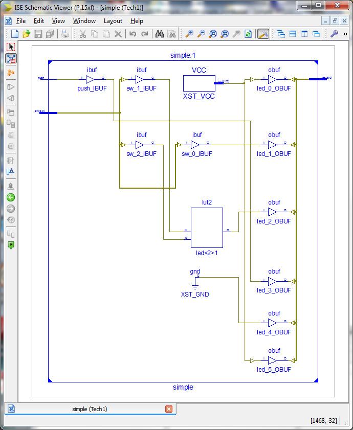
16 View Technology Schematic 16

17 Decoder Tutorial Demo Example sw0 sw1 sw2 led0 led1 led2 led3 led4 led5 led6 led7 17 Module 1

18 Verilog Source Code 18 Module 1
19 VHDL Process Signal assignments Verilog Concurrent statements always statement Continuous assignment - assign 19
20 Verilog wire and register data objects Wire net, connects two signals together wire clk, en; wire [15:0] a_bus; Reg register, holds its value from one procedural assignment statement to the next Does not imply a physical register depends on use reg [7:0] b_bus; 20
 & 0 ; Verilog Use colon : Concatenation {,} assign c_bus[3:0] = b_bus[7:4]; assign c_bus[5:0] = {b_bus[7], a_bus[6:3], 1 b0};")
21 Index and Slice VHDL Use to and downto to specify slice Concatenation & c_bus(3 downto 0) <= b_bus(7 downto 4); c_bus(5 downto 0) <= b_bus(7) & a_bus(6 downto 3) & 0 ; Verilog Use colon : Concatenation {,} assign c_bus[3:0] = b_bus[7:4]; assign c_bus[5:0] = {b_bus[7], a_bus[6:3], 1 b0}; 21
22 Declare internal wires: Internal wires 22
23 VHDL reside in process statement Verilog Sequential Statements reside in an always statement if statements (no endif) case statements (endcase) for, repeat while loop statements Note: use begin and end to block sequential statements 23
 event control operator begin.. end block statement note reg for y 24")
24 Decoder always statement 2 to 4 decoder with enable Combinational logic using always statement with sensitivity list similar to VHDL process for cyclic behavior (@) event control operator begin.. end block statement note reg for y 24
25 Decoder (cont d) Combinational logic using always statement with sensitivity list similar to VHDL process for cyclic behavior event control operator begin.. end block statement Statements execute sequentially if statement Sensitivity list case statement (a or b or c) Note: case expression can concatenate signals ({,}) Verilog 2001 allows comma-separated list (a, b, c) 25

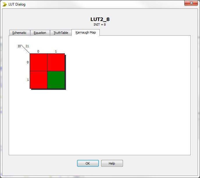
26 Decoder CASE statement CASE is better for this type of design - no priority Exactly same logic produced 26

27 Decoder 3 to 8 with CASE 27
 i0 i1 i2 i3 q a b")
28 MUX example Example multiplexer with conditional operator Selects different values for the target signal priority associated with series of conditions (similar to an IF statement) i0 i1 i2 i3 q a b 28

 + (I0 *!")
29 Synthesis Results Technology Schematic O = ((I0 * I1 * I3) + (!I0 * I1 * I4) + (!I0 *!I1 * I5) + (I0 *!I1 * I2)); 29

30 Mux with CASE statement Include all inputs on sensitivity list Elaborating module <mux_case>. WARNING:HDLCompiler:91 - "C:\ece3829\mux_case\mux_case.v" Line 34: Signal <i> missing in the sensitivity list is added for synthesis purposes. HDL and postsynthesis simulations may differ as a result. 30

31 Mux fixed sensitivity list Exact same logic produced as using conditional operator 31

32 Priority Encoder Priority Encoder using conditional operator Priority order determined by sequence similar to if-else statement 32

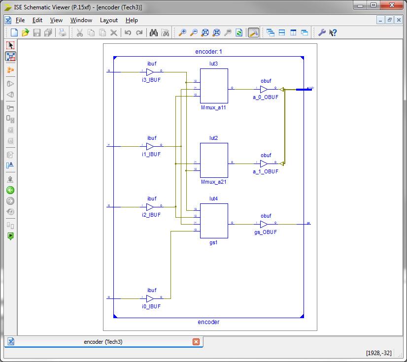
33 Encoder Technology Schematic ========================================================================= * HDL Synthesis * ========================================================================= Synthesizing Unit <encoder>. Related source file is "C:\ece3829\encoder\encoder.v". WARNING:Xst:647 - Input <i0> is never used. This port will be preserved and left unconnected if it belongs to a top-level block or it belongs to a sub-block and the hierarchy of this sub-block is preserved. Summary: inferred 2 Multiplexer(s). Unit <encoder> synthesized. =============================================================== HDL Synthesis Report Macro Statistics # Multiplexers : 2 2-bit 2-to-1 multiplexer : 2 =============================================================== 33

34 Add gs output 34
35 Synthesize - Design Summary ========================================================================= * Design Summary * ========================================================================= Clock Information: No clock signals found in this design Asynchronous Control Signals Information: No asynchronous control signals found in this design Timing Summary: Speed Grade: -3 Minimum period: No path found Minimum input arrival time before clock: No path found Maximum output required time after clock: No path found Maximum combinational path delay: 5.456ns ========================================================================= 35
36 Implement Design Device Utilization Summary: Slice Logic Utilization: Number of Slice Registers: 0 out of 18,224 0% Number of Slice LUTs: 2 out of 9,112 1% Number used as logic: 2 out of 9,112 1% Number using O6 output only: 1 Number using O5 output only: 0 Number using O5 and O6: 1 Number used as ROM: 0 Number used as Memory: 0 out of 2,176 0% Slice Logic Distribution: Number of occupied Slices: 2 out of 2,278 1% Number of MUXCYs used: 0 out of 4,556 0% Number of LUT Flip Flop pairs used: 2 Number with an unused Flip Flop: 2 out of 2 100% Number with an unused LUT: 0 out of 2 0% Number of fully used LUT-FF pairs: 0 out of 2 0% Number of slice register sites lost to control set restrictions: 0 out of 18,224 0% 36
37 Creating adder using LUTs 37
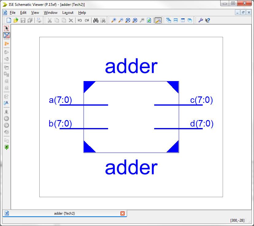
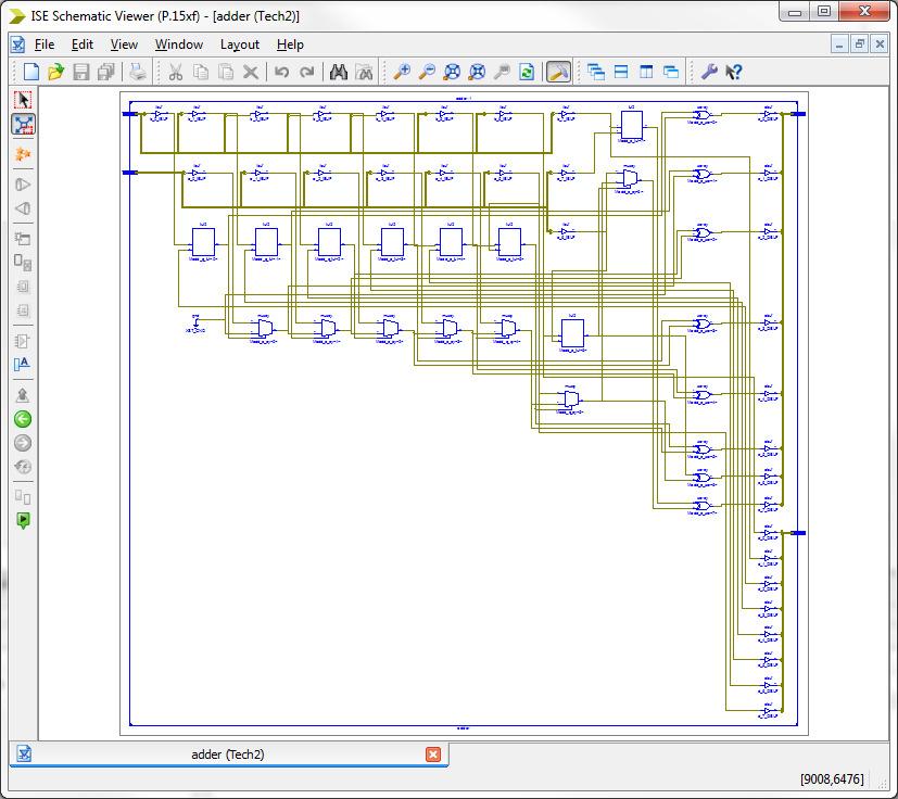
38 Technology Schematic 38

39 Example of simple mistake No errors or warnings! 39
40 Top-Down Design Hierarchy Instantiate module (counter example with decoder) module decoder( input [3:0] count, output [6:0] seven_seg ); // instantiate decoder module in counter // using position of ports decoder d1 (count_val, seven_seg_val); // or using formal and actual names decoder d1 (.count(count_val),.seven_seg(seven_seg_val)); 40


41 Tri-state example Using conditional operator in continuous assignment 41
Verilog. Verilog for Synthesis
 Verilog Verilog for Synthesis 1 Verilog background 1983: Gateway Design Automation released Verilog HDL Verilog and simulator 1985: Verilog enhanced version Verilog-XL 1987: Verilog-XL becoming more popular
EE260: Digital Design, Spring 2018
 Topics Verilog Module 1 Introduction Yao Zheng (Based on the slides of Prof. Jim Duckworth) Background to Verilog Introduction to language Programmable Logic Devices CPLDs and FPGAs FPGA architecture Nexys
Verilog Sequential Logic. Verilog for Synthesis Rev C (module 3 and 4)
") Verilog Sequential Logic Verilog for Synthesis Rev C (module 3 and 4) Jim Duckworth, WPI 1 Sequential Logic Module 3 Latches and Flip-Flops Implemented by using signals in always statements with edge-triggered
Verilog Sequential Logic Verilog for Synthesis Rev C (module 3 and 4) Jim Duckworth, WPI 1 Sequential Logic Module 3 Latches and Flip-Flops Implemented by using signals in always statements with edge-triggered
ECE 2300 Digital Logic & Computer Organization. More Sequential Logic Verilog
 ECE 2300 Digital Logic & Computer Organization Spring 2018 More Sequential Logic Verilog Lecture 7: 1 Announcements HW3 will be posted tonight Prelim 1 Thursday March 1, in class Coverage: Lectures 1~7
ECE 574: Modeling and Synthesis of Digital Systems using Verilog and VHDL. Fall 2017 Final Exam (6.00 to 8.30pm) Verilog SOLUTIONS
 Verilog SOLUTIONS") ECE 574: Modeling and Synthesis of Digital Systems using Verilog and VHDL Fall 2017 Final Exam (6.00 to 8.30pm) Verilog SOLUTIONS Note: Closed book no notes or other material allowed apart from the one
ECE 574: Modeling and Synthesis of Digital Systems using Verilog and VHDL Fall 2017 Final Exam (6.00 to 8.30pm) Verilog SOLUTIONS Note: Closed book no notes or other material allowed apart from the one
Hardware Description Language VHDL (1) Introduction
 Introduction") Hardware Description Language VHDL (1) Introduction Digital Radiation Measurement and Spectroscopy NE/RHP 537 Introduction Hardware description language (HDL) Intended to describe circuits textually, for
Hardware Description Language VHDL (1) Introduction Digital Radiation Measurement and Spectroscopy NE/RHP 537 Introduction Hardware description language (HDL) Intended to describe circuits textually, for
Computer Aided Design Basic Syntax Gate Level Modeling Behavioral Modeling. Verilog
 Verilog Radek Pelánek and Šimon Řeřucha Contents 1 Computer Aided Design 2 Basic Syntax 3 Gate Level Modeling 4 Behavioral Modeling Computer Aided Design Hardware Description Languages (HDL) Verilog C
Lab 3: Standard Combinational Components
 Lab 3: Standard Combinational Components Purpose In this lab you will implement several combinational circuits on the DE1 development board to test and verify their operations. Introduction Using a high-level
Lecture #2: Verilog HDL
 Lecture #2: Verilog HDL Paul Hartke Phartke@stanford.edu Stanford EE183 April 8, 2002 EE183 Design Process Understand problem and generate block diagram of solution Code block diagram in verilog HDL Synthesize
Digital Design with FPGAs. By Neeraj Kulkarni
 Digital Design with FPGAs By Neeraj Kulkarni Some Basic Electronics Basic Elements: Gates: And, Or, Nor, Nand, Xor.. Memory elements: Flip Flops, Registers.. Techniques to design a circuit using basic
Abi Farsoni, Department of Nuclear Engineering and Radiation Health Physics, Oregon State University
 Hardware description language (HDL) Intended to describe circuits textually, for a computer to read Evolved starting in the 1970s and 1980s Popular languages today include: VHDL Defined in 1980s by U.S.
Note: Closed book no notes or other material allowed, no calculators or other electronic devices.
 ECE 574: Modeling and Synthesis of Digital Systems using Verilog and VHDL Fall 2017 Exam Review Note: Closed book no notes or other material allowed, no calculators or other electronic devices. One page
FPGA Design Challenge :Techkriti 14 Digital Design using Verilog Part 1
 FPGA Design Challenge :Techkriti 14 Digital Design using Verilog Part 1 Anurag Dwivedi Digital Design : Bottom Up Approach Basic Block - Gates Digital Design : Bottom Up Approach Gates -> Flip Flops Digital
14:332:231 DIGITAL LOGIC DESIGN. Hardware Description Languages
 14:332:231 DIGITAL LOGIC DESIGN Ivan Marsic, Rutgers University Electrical & Computer Engineering Fall 2013 Lecture #22: Introduction to Verilog Hardware Description Languages Basic idea: Language constructs
FPGA: FIELD PROGRAMMABLE GATE ARRAY Verilog: a hardware description language. Reference: [1]
![FPGA: FIELD PROGRAMMABLE GATE ARRAY Verilog: a hardware description language. Reference: [1]](/thumbs/80/81661285.jpg "FPGA: FIELD PROGRAMMABLE GATE ARRAY Verilog: a hardware description language. Reference: [1]") FPGA: FIELD PROGRAMMABLE GATE ARRAY Verilog: a hardware description language Reference: [] FIELD PROGRAMMABLE GATE ARRAY FPGA is a hardware logic device that is programmable Logic functions may be programmed
FPGA: FIELD PROGRAMMABLE GATE ARRAY Verilog: a hardware description language Reference: [] FIELD PROGRAMMABLE GATE ARRAY FPGA is a hardware logic device that is programmable Logic functions may be programmed
Introduction to Verilog HDL
 Introduction to Verilog HDL Ben Abdallah Abderazek National University of Electro-communications, Tokyo, Graduate School of information Systems May 2004 04/09/08 1 What you will understand after having
Verilog. What is Verilog? VHDL vs. Verilog. Hardware description language: Two major languages. Many EDA tools support HDL-based design
 Verilog What is Verilog? Hardware description language: Are used to describe digital system in text form Used for modeling, simulation, design Two major languages Verilog (IEEE 1364), latest version is
Introduction. Why Use HDL? Simulation output. Explanation
 Introduction Verilog HDL is a Hardware Description Language (HDL) HDL is a language used to describe a digital system, for example, a computer or a component of a computer. Most popular HDLs are VHDL and
Verilog for High Performance
 Verilog for High Performance Course Description This course provides all necessary theoretical and practical know-how to write synthesizable HDL code through Verilog standard language. The course goes
CSE140L: Components and Design Techniques for Digital Systems Lab
 CSE140L: Components and Design Techniques for Digital Systems Lab Tajana Simunic Rosing Source: Vahid, Katz, Culler 1 Announcements & Outline Lab 4 due; demo signup times listed on the cse140l site Check
EEL 4783: Hardware/Software Co-design with FPGAs
 EEL 4783: Hardware/Software Co-design with FPGAs Lecture 8: Short Introduction to Verilog * Prof. Mingjie Lin * Beased on notes of Turfts lecture 1 Overview Recap + Questions? What is a HDL? Why do we
Register Transfer Level in Verilog: Part I
 Source: M. Morris Mano and Michael D. Ciletti, Digital Design, 4rd Edition, 2007, Prentice Hall. Register Transfer Level in Verilog: Part I Lan-Da Van ( 范倫達 ), Ph. D. Department of Computer Science National
Verilog. Reminder: Lab #1 due tonight! Fall 2008 Lecture 3
 Verilog Hardware Description Languages Verilog -- structural: modules, instances -- dataflow: continuous assignment -- sequential behavior: always blocks -- pitfalls -- other useful features Reminder:
A Verilog Primer. An Overview of Verilog for Digital Design and Simulation
 A Verilog Primer An Overview of Verilog for Digital Design and Simulation John Wright Vighnesh Iyer Department of Electrical Engineering and Computer Sciences College of Engineering, University of California,
Department of Computer Science and Electrical Engineering. Intro to Verilog II
 Department of Computer Science and Electrical Engineering Intro to Verilog II http://6004.csail.mit.edu/6.371/handouts/l0{2,3,4}.pdf http://www.asic-world.com/verilog/ http://www.verilogtutorial.info/
Lecture 3: Modeling in VHDL. EE 3610 Digital Systems
 EE 3610: Digital Systems 1 Lecture 3: Modeling in VHDL VHDL: Overview 2 VHDL VHSIC Hardware Description Language VHSIC=Very High Speed Integrated Circuit Programming language for modelling of hardware
Verilog Design Principles
 16 h7fex // 16-bit value, low order 4 bits unknown 8 bxx001100 // 8-bit value, most significant 2 bits unknown. 8 hzz // 8-bit value, all bits high impedance. Verilog Design Principles ECGR2181 Extra Notes
Verilog Fundamentals. Shubham Singh. Junior Undergrad. Electrical Engineering
 Verilog Fundamentals Shubham Singh Junior Undergrad. Electrical Engineering VERILOG FUNDAMENTALS HDLs HISTORY HOW FPGA & VERILOG ARE RELATED CODING IN VERILOG HDLs HISTORY HDL HARDWARE DESCRIPTION LANGUAGE
CSE140L: Components and Design
 CSE140L: Components and Design Techniques for Digital Systems Lab Tajana Simunic Rosing Source: Vahid, Katz, Culler 1 Grade distribution: 70% Labs 35% Lab 4 30% Lab 3 20% Lab 2 15% Lab 1 30% Final exam
EEL 4783: HDL in Digital System Design
 EEL 4783: HDL in Digital System Design Lecture 15: Logic Synthesis with Verilog Prof. Mingjie Lin 1 Verilog Synthesis Synthesis vs. Compilation Descriptions mapped to hardware Verilog design patterns for
Digital Design with SystemVerilog
 Digital Design with SystemVerilog Prof. Stephen A. Edwards Columbia University Spring 25 Synchronous Digital Design Combinational Logic Sequential Logic Summary of Modeling Styles Testbenches Why HDLs?
A Brief Introduction to Verilog Hardware Definition Language (HDL)
") www.realdigital.org A Brief Introduction to Verilog Hardware Definition Language (HDL) Forward Verilog is a Hardware Description language (HDL) that is used to define the structure and/or behavior of digital
www.realdigital.org A Brief Introduction to Verilog Hardware Definition Language (HDL) Forward Verilog is a Hardware Description language (HDL) that is used to define the structure and/or behavior of digital
!"#$%&&"'(')"*+"%,%-".#"'/"'.001$$"
*+%,%-.#'/'.001$$") !"#$%&&"'(')"*+"%,%-".#"'/"'.001$$"!!"#$%&'#()#*+"+#,-."/0110#230#4."50",+"+#)6# 6+-+#(.6+-0#)4475.8)60#0/#.65-0#230#9+**+"+# 2.48).-0#(.6+-0#! 2+"*5."5*:#,."/0110#;)**0! *),".6*:#-.99-0*0"5."+#2+660,.40"5)#;)*)2)#
!"#$%&&"'(')"*+"%,%-".#"'/"'.001$$"!!"#$%&'#()#*+"+#,-."/0110#230#4."50",+"+#)6# 6+-+#(.6+-0#)4475.8)60#0/#.65-0#230#9+**+"+# 2.48).-0#(.6+-0#! 2+"*5."5*:#,."/0110#;)**0! *),".6*:#-.99-0*0"5."+#2+660,.40"5)#;)*)2)#
structure syntax different levels of abstraction
 This and the next lectures are about Verilog HDL, which, together with another language VHDL, are the most popular hardware languages used in industry. Verilog is only a tool; this course is about digital
Here is a list of lecture objectives. They are provided for you to reflect on what you are supposed to learn, rather than an introduction to this
 This and the next lectures are about Verilog HDL, which, together with another language VHDL, are the most popular hardware languages used in industry. Verilog is only a tool; this course is about digital
VERILOG 2: LANGUAGE BASICS
 VERILOG 2: LANGUAGE BASICS Verilog module Modules are basic building blocks. These are two example module definitions which you should use: // Safer traditional method module abc (in1, in2, out); input
Combinational Logic II
 Combinational Logic II Ranga Rodrigo July 26, 2009 1 Binary Adder-Subtractor Digital computers perform variety of information processing tasks. Among the functions encountered are the various arithmetic
Introduction to Verilog/System Verilog
 NTUEE DCLAB Feb. 27, 2018 Introduction to Verilog/System Verilog Presenter: Yao-Pin Wang 王耀斌 Advisor: Prof. Chia-Hsiang Yang 楊家驤 Dept. of Electrical Engineering, NTU National Taiwan University What is
Verilog for Synthesis Ing. Pullini Antonio
 Verilog for Synthesis Ing. Pullini Antonio antonio.pullini@epfl.ch Outline Introduction to Verilog HDL Describing combinational logic Inference of basic combinational blocks Describing sequential circuits
Verilog 1 - Fundamentals
 Verilog 1 - Fundamentals FA FA FA FA module adder( input [3:0] A, B, output cout, output [3:0] S ); wire c0, c1, c2; FA fa0( A[0], B[0], 1 b0, c0, S[0] ); FA fa1( A[1], B[1], c0, c1, S[1] ); FA fa2( A[2],
Spring 2017 EE 3613: Computer Organization Chapter 5: Processor: Datapath & Control - 2 Verilog Tutorial
 Spring 2017 EE 3613: Computer Organization Chapter 5: Processor: Datapath & Control - 2 Verilog Tutorial Avinash Kodi Department of Electrical Engineering & Computer Science Ohio University, Athens, Ohio
EN2911X: Reconfigurable Computing Lecture 05: Verilog (2)
") EN2911X: Lecture 05: Verilog (2) Prof. Sherief Reda Division of Engineering, Brown University Fall 09 http://scale.engin.brown.edu Dataflow modeling Module is designed by specifying the data flow, where
EN2911X: Lecture 05: Verilog (2) Prof. Sherief Reda Division of Engineering, Brown University Fall 09 http://scale.engin.brown.edu Dataflow modeling Module is designed by specifying the data flow, where
Hardware Description Languages (HDLs) Verilog
 Verilog") Hardware Description Languages (HDLs) Verilog Material from Mano & Ciletti book By Kurtulus KULLU Ankara University What are HDLs? A Hardware Description Language resembles a programming language specifically
Hardware Description Languages (HDLs) Verilog Material from Mano & Ciletti book By Kurtulus KULLU Ankara University What are HDLs? A Hardware Description Language resembles a programming language specifically
Schematic design. Gate level design. 0 EDA (Electronic Design Assistance) 0 Classical design. 0 Computer based language
 0 Classical design. 0 Computer based language") 1 / 15 2014/11/20 0 EDA (Electronic Design Assistance) 0 Computer based language 0 HDL (Hardware Description Language) 0 Verilog HDL 0 Created by Gateway Design Automation Corp. in 1983 First modern hardware
1 / 15 2014/11/20 0 EDA (Electronic Design Assistance) 0 Computer based language 0 HDL (Hardware Description Language) 0 Verilog HDL 0 Created by Gateway Design Automation Corp. in 1983 First modern hardware
EECS150 - Digital Design Lecture 4 - Verilog Introduction. Outline
 EECS150 - Digital Design Lecture 4 - Verilog Introduction Feb 3, 2009 John Wawrzynek Spring 2009 EECS150 - Lec05-Verilog Page 1 Outline Background and History of Hardware Description Brief Introduction
HDL. Hardware Description Languages extensively used for:
 HDL Hardware Description Languages extensively used for: Describing (digital) hardware (formal documentation) Simulating it Verifying it Synthesizing it (first step of modern design flow) 2 main options:
Brief Introduction to Verilog HDL (Part 1)
") BUDAPEST UNIVERSITY OF TECHNOLOGY AND ECONOMICS FACULTY OF ELECTRICAL ENGINEERING AND INFORMATICS DEPARTMENT OF MEASUREMENT AND INFORMATION SYSTEMS Brief Introduction to Verilog HDL (Part 1) Tamás Raikovich
BUDAPEST UNIVERSITY OF TECHNOLOGY AND ECONOMICS FACULTY OF ELECTRICAL ENGINEERING AND INFORMATICS DEPARTMENT OF MEASUREMENT AND INFORMATION SYSTEMS Brief Introduction to Verilog HDL (Part 1) Tamás Raikovich
Programming with HDLs
 Programming with HDLs Paul Chow February 11, 2008 1 Introduction The purpose of this document is to encourage the proper approach or mindset for programming in a hardware description language (HDL), particularly
HDLs and SystemVerilog. Digital Computer Design
 HDLs and SystemVerilog Digital Computer Design Logic Arrays Gates can be organized into regular arrays. If the connections are made programmable, these logic arrays can be configured to perform any function
Verilog introduction. Embedded and Ambient Systems Lab
 Verilog introduction Embedded and Ambient Systems Lab Purpose of HDL languages Modeling hardware behavior Large part of these languages can only be used for simulation, not for hardware generation (synthesis)
EN2911X: Reconfigurable Computing Topic 02: Hardware Definition Languages
 EN2911X: Reconfigurable Computing Topic 02: Hardware Definition Languages Professor Sherief Reda http://scale.engin.brown.edu School of Engineering Brown University Spring 2014 1 Introduction to Verilog
Advanced Digital Design Using FPGA. Dr. Shahrokh Abadi
 Advanced Digital Design Using FPGA Dr. Shahrokh Abadi 1 Venue Computer Lab: Tuesdays 10 12 am (Fixed) Computer Lab: Wednesday 10-12 am (Every other odd weeks) Note: Due to some unpredicted problems with
Verilog Design Principles
 16 h7fex // 16-bit value, low order 4 bits unknown 8 bxx001100 // 8-bit value, most significant 2 bits unknown. 8 hzz // 8-bit value, all bits high impedance. Verilog Design Principles ECGR2181 Extra Notes
CSCB58 - Lab 3. Prelab /3 Part I (in-lab) /2 Part II (in-lab) /2 TOTAL /8
 /2 Part II (in-lab) /2 TOTAL /8") CSCB58 - Lab 3 Latches, Flip-flops, and Registers Learning Objectives The purpose of this exercise is to investigate the fundamental synchronous logic elements: latches, flip-flops, and registers. Prelab
CSCB58 - Lab 3 Latches, Flip-flops, and Registers Learning Objectives The purpose of this exercise is to investigate the fundamental synchronous logic elements: latches, flip-flops, and registers. Prelab
Synthesis vs. Compilation Descriptions mapped to hardware Verilog design patterns for best synthesis. Spring 2007 Lec #8 -- HW Synthesis 1
 Verilog Synthesis Synthesis vs. Compilation Descriptions mapped to hardware Verilog design patterns for best synthesis Spring 2007 Lec #8 -- HW Synthesis 1 Logic Synthesis Verilog and VHDL started out
EECS150 - Digital Design Lecture 5 - Verilog Logic Synthesis
 EECS150 - Digital Design Lecture 5 - Verilog Logic Synthesis Jan 31, 2012 John Wawrzynek Spring 2012 EECS150 - Lec05-verilog_synth Page 1 Outline Quick review of essentials of state elements Finite State
Spiral 1 / Unit 4 Verilog HDL. Digital Circuit Design Steps. Digital Circuit Design OVERVIEW. Mark Redekopp. Description. Verification.
 1-4.1 1-4.2 Spiral 1 / Unit 4 Verilog HDL Mark Redekopp OVERVIEW 1-4.3 1-4.4 Digital Circuit Design Steps Digital Circuit Design Description Design and computer-entry of circuit Verification Input Stimulus
Lecture 12 VHDL Synthesis
 CPE 487: Digital System Design Spring 2018 Lecture 12 VHDL Synthesis Bryan Ackland Department of Electrical and Computer Engineering Stevens Institute of Technology Hoboken, NJ 07030 1 What is Synthesis?
N-input EX-NOR gate. N-output inverter. N-input NOR gate
 Hardware Description Language HDL Introduction HDL is a hardware description language used to design and document electronic systems. HDL allows designers to design at various levels of abstraction. It
EN164: Design of Computing Systems Lecture 06: Lab Foundations / Verilog 2
 EN164: Design of Computing Systems Lecture 06: Lab Foundations / Verilog 2 Professor Sherief Reda http://scaleenginbrownedu Electrical Sciences and Computer Engineering School of Engineering Brown University
Introduction to Verilog HDL. Verilog 1
 Introduction to HDL Hardware Description Language (HDL) High-Level Programming Language Special constructs to model microelectronic circuits Describe the operation of a circuit at various levels of abstraction
Logic Synthesis. EECS150 - Digital Design Lecture 6 - Synthesis
 Logic Synthesis Verilog and VHDL started out as simulation languages, but quickly people wrote programs to automatically convert Verilog code into low-level circuit descriptions (netlists). EECS150 - Digital
Arithmetic Operators There are two types of operators: binary and unary Binary operators:
 Verilog operators operate on several data types to produce an output Not all Verilog operators are synthesible (can produce gates) Some operators are similar to those in the C language Remember, you are
ENGN1640: Design of Computing Systems Topic 02: Design/Lab Foundations
 ENGN1640: Design of Computing Systems Topic 02: Design/Lab Foundations Professor Sherief Reda http://scale.engin.brown.edu School of Engineering Brown University Spring 2017 1 Topics 1. Programmable logic
Building Combinatorial Circuit Using Behavioral Modeling Lab
 Building Combinatorial Circuit Using Behavioral Modeling Lab Overview: In this lab you will learn how to model a combinatorial circuit using behavioral modeling style of Verilog HDL. You will model a combinatorial
Hardware Description Languages: Verilog
 Hardware Description Languages: Verilog Verilog Structural Models (Combinational) Behavioral Models Syntax Examples CS 150 - Fall 2005 - Lecture #4: Verilog - 1 Quick History of HDLs ISP (circa 1977) -
Digital Design (VIMIAA01) Introduction to the Verilog HDL
 Introduction to the Verilog HDL") BUDAPEST UNIVERSITY OF TECHNOLOGY AND ECONOMICS FACULTY OF ELECTRICAL ENGINEERING AND INFORMATICS DEPARTMENT OF MEASUREMENT AND INFORMATION SYSTEMS Digital Design (VIMIAA01) Introduction to the Verilog
BUDAPEST UNIVERSITY OF TECHNOLOGY AND ECONOMICS FACULTY OF ELECTRICAL ENGINEERING AND INFORMATICS DEPARTMENT OF MEASUREMENT AND INFORMATION SYSTEMS Digital Design (VIMIAA01) Introduction to the Verilog
Sequential Logic - Module 5
 Sequential Logic Module 5 Jim Duckworth, WPI 1 Latches and Flip-Flops Implemented by using signals in IF statements that are not completely specified Necessary latches or registers are inferred by the
register:a group of binary cells suitable for holding binary information flip-flops + gates
 9 차시 1 Ch. 6 Registers and Counters 6.1 Registers register:a group of binary cells suitable for holding binary information flip-flops + gates control when and how new information is transferred into the
ECE 448 Lecture 3. Combinational-Circuit Building Blocks. Data Flow Modeling of Combinational Logic
 ECE 448 Lecture 3 Combinational-Circuit Building Blocks Data Flow Modeling of Combinational Logic George Mason University Reading Required P. Chu, FPGA Prototyping by VHDL Examples Chapter 3, RT-level
Recommended Design Techniques for ECE241 Project Franjo Plavec Department of Electrical and Computer Engineering University of Toronto
 Recommed Design Techniques for ECE241 Project Franjo Plavec Department of Electrical and Computer Engineering University of Toronto DISCLAIMER: The information contained in this document does NOT contain
This Lecture. Some components (useful for the homework) Verilog HDL (will continue next lecture)
 Verilog HDL (will continue next lecture)") Last Lecture The basic component of a digital circuit is the MOS transistor Transistor have instrinsic resistance and capacitance, so voltage values in the circuit take some time to change ( delay ) There
Last Lecture The basic component of a digital circuit is the MOS transistor Transistor have instrinsic resistance and capacitance, so voltage values in the circuit take some time to change ( delay ) There
ECE 448 Lecture 3. Combinational-Circuit Building Blocks. Data Flow Modeling of Combinational Logic
 ECE 448 Lecture 3 Combinational-Circuit Building Blocks Data Flow Modeling of Combinational Logic George Mason University Reading Required P. Chu, FPGA Prototyping by VHDL Examples Chapter 3, RT-level
Lecture 7. Standard ICs FPGA (Field Programmable Gate Array) VHDL (Very-high-speed integrated circuits. Hardware Description Language)
 VHDL (Very-high-speed integrated circuits. Hardware Description Language)") Standard ICs FPGA (Field Programmable Gate Array) VHDL (Very-high-speed integrated circuits Hardware Description Language) 1 Standard ICs PLD: Programmable Logic Device CPLD: Complex PLD FPGA: Field Programmable
Standard ICs FPGA (Field Programmable Gate Array) VHDL (Very-high-speed integrated circuits Hardware Description Language) 1 Standard ICs PLD: Programmable Logic Device CPLD: Complex PLD FPGA: Field Programmable
ENGN1640: Design of Computing Systems Topic 02: Design/Lab Foundations
 ENGN1640: Design of Computing Systems Topic 02: Design/Lab Foundations Professor Sherief Reda http://scale.engin.brown.edu School of Engineering Brown University Spring 2016 1 Topics 1. Programmable logic
PINE TRAINING ACADEMY
 PINE TRAINING ACADEMY Course Module A d d r e s s D - 5 5 7, G o v i n d p u r a m, G h a z i a b a d, U. P., 2 0 1 0 1 3, I n d i a Digital Logic System Design using Gates/Verilog or VHDL and Implementation
VHDL Sample Slides Rev Sample Slides from the 2-day and 4-day VHDL Training Courses
 VHDL Sample Slides from the 2-day and 4-day VHDL Training Courses Rev. 4.7 VHDL 2011 TM Associates, Inc. 1-1 These sample slides are taken from the 4-day basic VHDL training course. They are from a variety
Topics. Midterm Finish Chapter 7
 Lecture 9 Topics Midterm Finish Chapter 7 ROM (review) Memory device in which permanent binary information is stored. Example: 32 x 8 ROM Five input lines (2 5 = 32) 32 outputs, each representing a memory
ECE 3401 Lecture 10. More on VHDL
 ECE 3401 Lecture 10 More on VHDL Outline More on VHDL Some VHDL Basics Data Types Operators Delay Models VHDL for Simulation VHDL for Synthesis 1 Data Types Every signal has a type, type specifies possible
Programmable Logic Devices Verilog VII CMPE 415
 Synthesis of Combinational Logic In theory, synthesis tools automatically create an optimal gate-level realization of a design from a high level HDL description. In reality, the results depend on the skill
Speaker: Kayting Adviser: Prof. An-Yeu Wu Date: 2009/11/23
 98-1 Under-Graduate Project Synthesis of Combinational Logic Speaker: Kayting Adviser: Prof. An-Yeu Wu Date: 2009/11/23 What is synthesis? Outline Behavior Description for Synthesis Write Efficient HDL
Hardware Design Environments. Dr. Mahdi Abbasi Computer Engineering Department Bu-Ali Sina University
 Hardware Design Environments Dr. Mahdi Abbasi Computer Engineering Department Bu-Ali Sina University Outline Welcome to COE 405 Digital System Design Design Domains and Levels of Abstractions Synthesis
Synthesis of Language Constructs. 5/10/04 & 5/13/04 Hardware Description Languages and Synthesis
 Synthesis of Language Constructs 1 Nets Nets declared to be input or output ports are retained Internal nets may be eliminated due to logic optimization User may force a net to exist trireg, tri0, tri1
Verilog Hardware Description Language ROOM: B405
 Verilog Hardware Description Language HONG@IS.NAIST.JP ROOM: B405 Content Lecture 1: Computer organization and performance evaluation metrics Lecture 2: Processor architecture and memory system Lecture
VHDL for Synthesis. Course Description. Course Duration. Goals
 VHDL for Synthesis Course Description This course provides all necessary theoretical and practical know how to write an efficient synthesizable HDL code through VHDL standard language. The course goes
ELCT 501: Digital System Design
 ELCT 501: Digital System Lecture 4: CAD tools (Continued) Dr. Mohamed Abd El Ghany, Basic VHDL Concept Via an Example Problem: write VHDL code for 1-bit adder 4-bit adder 2 1-bit adder Inputs: A (1 bit)
IT T35 Digital system desigm y - ii /s - iii
 UNIT - V Introduction to Verilog Hardware Description Language Introduction HDL for combinational circuits Sequential circuits Registers and counters HDL description for binary multiplier. 5.1 INTRODUCTION
Lecture 4. VHDL Fundamentals. George Mason University
 Lecture 4 VHDL Fundamentals George Mason University Required reading P. Chu, RTL Hardware Design using VHDL Chapter 3, Basic Language Constructs of VHDL 2 Design Entity ECE 448 FPGA and ASIC Design with
Lecture 8: Combinational Verilog. CSE 370, Autumn 2007 Benjamin Ylvisaker. Where We Are. Last lecture: Minimization with K!maps
 Lecture 8: Combinational Verilog CSE 370, Autumn 2007 Benjamin Ylvisaker Where We Are Last lecture: Minimization with K!maps This lecture: Combinational Verilog Next lecture: ROMs, PLAs and PALs, oh my!
University of Toronto Faculty of Applied Science and Engineering Edward S. Rogers Sr. Department of Electrical and Computer Engineering
 University of Toronto Faculty of Applied Science and Engineering Edward S. Rogers Sr. Department of Electrical and Computer Engineering Final Examination ECE 241F - Digital Systems Examiners: S. Brown,
RIZALAFANDE CHE ISMAIL TKT. 3, BLOK A, PPK MIKRO-e KOMPLEKS PENGAJIAN KUKUM. SYNTHESIS OF COMBINATIONAL LOGIC (Chapter 8)
") RIZALAFANDE CHE ISMAIL TKT. 3, BLOK A, PPK MIKRO-e KOMPLEKS PENGAJIAN KUKUM SYNTHESIS OF COMBINATIONAL LOGIC (Chapter 8) HDL-BASED SYNTHESIS Modern ASIC design use HDL together with synthesis tool to create
RIZALAFANDE CHE ISMAIL TKT. 3, BLOK A, PPK MIKRO-e KOMPLEKS PENGAJIAN KUKUM SYNTHESIS OF COMBINATIONAL LOGIC (Chapter 8) HDL-BASED SYNTHESIS Modern ASIC design use HDL together with synthesis tool to create
ECEN 468 Advanced Logic Design
 ECEN 468 Advanced Logic Design Lecture 26: Verilog Operators ECEN 468 Lecture 26 Operators Operator Number of Operands Result Arithmetic 2 Binary word Bitwise 2 Binary word Reduction 1 Bit Logical 2 Boolean
Synthesis of Combinational and Sequential Circuits with Verilog
 Synthesis of Combinational and Sequential Circuits with Verilog What is Verilog? Hardware description language: Are used to describe digital system in text form Used for modeling, simulation, design Two
Hardware Description Languages: Verilog. Quick History of HDLs. Verilog/VHDL. Design Methodology. Verilog Introduction. Verilog.
 Hardware Description Languages: Verilog Quick History of HDLs Verilog Structural Models (Combinational) Behavioral Models Syntax Examples CS 150 - Fall 2005 - Lecture #4: Verilog - 1 ISP (circa 1977) -
Nikhil Gupta. FPGA Challenge Takneek 2012
 Nikhil Gupta FPGA Challenge Takneek 2012 RECAP FPGA Field Programmable Gate Array Matrix of logic gates Can be configured in any way by the user Codes for FPGA are executed in parallel Configured using
Contents. Appendix D Verilog Summary Page 1 of 16
 Appix D Verilog Summary Page 1 of 16 Contents Appix D Verilog Summary... 2 D.1 Basic Language Elements... 2 D.1.1 Keywords... 2 D.1.2 Comments... 2 D.1.3 Identifiers... 2 D.1.4 Numbers and Strings... 3
Topics. Verilog. Verilog vs. VHDL (2) Verilog vs. VHDL (1)
 Verilog vs. VHDL (1)") Topics Verilog Hardware modeling and simulation Event-driven simulation Basics of register-transfer design: data paths and controllers; ASM charts. High-level synthesis Initially a proprietary language,
Topics Verilog Hardware modeling and simulation Event-driven simulation Basics of register-transfer design: data paths and controllers; ASM charts. High-level synthesis Initially a proprietary language,
EECS150 - Digital Design Lecture 10 Logic Synthesis
 EECS150 - Digital Design Lecture 10 Logic Synthesis September 26, 2002 John Wawrzynek Fall 2002 EECS150 Lec10-synthesis Page 1 Logic Synthesis Verilog and VHDL stated out as simulation languages, but quickly
Hardware description languages
 Specifying digital circuits Schematics (what we ve done so far) Structural description Describe circuit as interconnected elements Build complex circuits using hierarchy Large circuits are unreadable Hardware
VHDL for Modeling - Module 10
 VHDL for Modeling Module 10 Jim Duckworth, WPI 1 Overview General examples AND model Flip-flop model SRAM Model Generics DDR SDRAM Model Constraints Metastability Block Statements Just for reference Jim