Verilog Tutorial 9/28/2015. Verilog Fundamentals. Originally designers used manual translation + bread boards for verification
|
|
|
- Cassandra Holmes
- 6 years ago
- Views:
Transcription


1 Verilog Fundamentals Verilog Tutorial History Data types Structural Verilog Functional Verilog Adapted from Krste Asanovic Originally designers used manual translation + bread boards for verification Hardware design languages enabled logic level simulation and verification Once design were written in HDLs tools could be used for automatic translation Primary Verilog data type is a bit-vector where bits can take on one of four values 1


2 The Verilog keyword wire is used to denote a standard hardware net Verilog includes ways to specify bit literals in various bases Data types Structural Verilog Functional Verilog Verilog Basics A Verilog module includes a module name and a port list A Verilog module includes a module name and a port list A module can instantiate other modules creating a module hierarchy 2


3 A module can instantiate other modules creating a module hierarchy A module can instantiate other modules creating a module hierarchy Verilog supports connecting ports by position and by name Let s review how to turn our schematic diagram into structural Verilog Let s review how to turn our schematic diagram into structural Verilog Data types Structural Verilog Functional Verilog Gate level Register transfer level High-level behavioral Verilog Fundamentals 3


4 Functional Verilog can roughly be divided into three abstraction levels Gate-level Verilog uses structural Verilog to connect primitive gates Continuous assignments statements assign one net to another or to a literal Using continuous assignments to implement an RTL four input mutliplexer Verilog RTL includes many operators in addition to basic boolean logic Verilog RTL operators 4


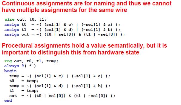
5 Always blocks have parallel inter-block and sequential intra-block sematics Always blocks have parallel inter-block and sequential intra-block sematics Always blocks have parallel inter-block and sequential intra-block sematics Always blocks have parallel inter-block and sequential intra-block sematics Always blocks have parallel inter-block and sequential intra-block sematics Continuous and procedural assignment statements are very different 5

6 Always blocks can contain more advanced control constructs What happens if the case statement is not complete? What happens if the case statement is not complete? So is this how we make latches and flipflops? more about Verilog execution semantics more about Verilog execution semantics 6

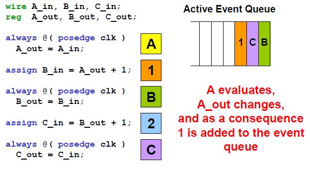

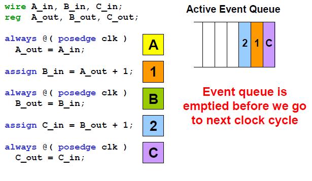
7 more about Verilog execution semantics more about Verilog execution sematics more about Verilog execution sematics more about Verilog execution semantics more about Verilog execution semantics more about Verilog execution sematics 7


8 more about Verilog execution sematics We didn t model what we expected due to Verilog execution semantics Non-blocking procedural assignments add an extra event queue Non-blocking procedural assignments add an extra event queue The order of non-blocking assignments does not matter Common patterns for latch and flip-flop inference 8


9 Writing Good Synthesizable Verilog Behavioral Verilog is used to model the abstract function of a hardware Verilog can be used to model the highlevel behavior of a hardware block Delay statements should only be used in test harnesses System tasks are used for test harnesses and simulation management Which abstraction is the right one? 9


10 Examples Mux4: Gate-level structural Verilog Mux4: Using continuous assignments Mux4: Behavioral style Mux4: Using always block Mux4: Always block permit more advanced sequential idioms 10

11 Parametrized mux4 Flip-flops Flip-flops with reset Register Register in terms of Flip-flops Static Elaboration: Generate 11


12 A simple state machine for valid/ready signals Implementing the control logic finite state machine in Verilog Implementing the control signal outputs for the finite state machine Implementing the state transitions for the finite state machine Take away points 12
Verilog Tutorial. Verilog Fundamentals. Originally designers used manual translation + bread boards for verification
 Verilog Fundamentals Verilog Tutorial History Data types Structural Verilog Functional Verilog Adapted from Krste Asanovic Originally designers used manual translation + bread boards for verification Hardware
Verilog 1 - Fundamentals
 Verilog 1 - Fundamentals FA FA FA FA module adder( input [3:0] A, B, output cout, output [3:0] S ); wire c0, c1, c2; FA fa0( A[0], B[0], 1 b0, c0, S[0] ); FA fa1( A[1], B[1], c0, c1, S[1] ); FA fa2( A[2],
Verilog 1 - Fundamentals
 Verilog 1 - Fundamentals FA FA FA FA module adder( input [3:0] A, B, output cout, output [3:0] S ); wire c0, c1, c2; FA fa0( A[0], B[0], 1 b0, c0, S[0] ); FA fa1( A[1], B[1], c0, c1, S[1] ); FA fa2( A[2],
ECE 2300 Digital Logic & Computer Organization. More Sequential Logic Verilog
 ECE 2300 Digital Logic & Computer Organization Spring 2018 More Sequential Logic Verilog Lecture 7: 1 Announcements HW3 will be posted tonight Prelim 1 Thursday March 1, in class Coverage: Lectures 1~7
EECS150 - Digital Design Lecture 5 - Verilog Logic Synthesis
 EECS150 - Digital Design Lecture 5 - Verilog Logic Synthesis Jan 31, 2012 John Wawrzynek Spring 2012 EECS150 - Lec05-verilog_synth Page 1 Outline Quick review of essentials of state elements Finite State
Verilog. What is Verilog? VHDL vs. Verilog. Hardware description language: Two major languages. Many EDA tools support HDL-based design
 Verilog What is Verilog? Hardware description language: Are used to describe digital system in text form Used for modeling, simulation, design Two major languages Verilog (IEEE 1364), latest version is
A Tutorial Introduction 1
 Preface From the Old to the New Acknowledgments xv xvii xxi 1 Verilog A Tutorial Introduction 1 Getting Started A Structural Description Simulating the binarytoeseg Driver Creating Ports For the Module
Synthesis of Combinational and Sequential Circuits with Verilog
 Synthesis of Combinational and Sequential Circuits with Verilog What is Verilog? Hardware description language: Are used to describe digital system in text form Used for modeling, simulation, design Two
The Verilog Hardware Description Language
 Donald Thomas Philip Moorby The Verilog Hardware Description Language Fifth Edition 4y Spri nnger Preface From the Old to the New Acknowledgments xv xvii xxi 1 Verilog A Tutorial Introduction Getting Started
Behavioral Modeling and Timing Constraints
 Lab Workbook Introduction Behavioral modeling was introduced in Lab 1 as one of three widely used modeling styles. Additional capabilities with respect to testbenches were further introduced in Lab 4.
Verilog for High Performance
 Verilog for High Performance Course Description This course provides all necessary theoretical and practical know-how to write synthesizable HDL code through Verilog standard language. The course goes
MLR Institute of Technology
 MLR Institute of Technology Laxma Reddy Avenue, Dundigal, Quthbullapur (M), Hyderabad 500 043 Course Name Course Code Class Branch ELECTRONICS AND COMMUNICATIONS ENGINEERING QUESTION BANK : DIGITAL DESIGN
Sunburst Design - Verilog-2001 Design & Best Coding Practices by Recognized Verilog & SystemVerilog Guru, Cliff Cummings of Sunburst Design, Inc.
 World Class Verilog & SystemVerilog Training Sunburst Design - Verilog-2001 Design & Best Coding Practices by Recognized Verilog & SystemVerilog Guru, Cliff Cummings of Sunburst Design, Inc. Cliff Cummings
Lecture 15: System Modeling and Verilog
 Lecture 15: System Modeling and Verilog Slides courtesy of Deming Chen Intro. VLSI System Design Outline Outline Modeling Digital Systems Introduction to Verilog HDL Use of Verilog HDL in Synthesis Reading
Verilog for Synthesis Ing. Pullini Antonio
 Verilog for Synthesis Ing. Pullini Antonio antonio.pullini@epfl.ch Outline Introduction to Verilog HDL Describing combinational logic Inference of basic combinational blocks Describing sequential circuits
Image Courtesy CS250 Section 2. Yunsup Lee 9/4/09
 CS250 Section 2 Image Courtesy www.intel.com Yunsup Lee 9/4/09 Upcoming dates! 9/8/09 (12:30pm) - Lab 1 due (No late days for Lab 1!)! Submit using SVN (source, build, writeup)! 9/8/09 - Lab 2 out! Write
ECE 2300 Digital Logic & Computer Organization. More Verilog Finite State Machines
 ECE 2300 Digital Logic & Computer Organization Spring 2018 More Verilog Finite Machines Lecture 8: 1 Prelim 1, Thursday 3/1, 1:25pm, 75 mins Arrive early by 1:20pm Review sessions Announcements Monday
Course Details: Webpage
 Course Details: Webpage What you will be able to do after this class.! Write top-notch System Verilog! Employ top-notch HW Design Practices! Design your own processor! Design pipelined hardware! Design
Synthesis vs. Compilation Descriptions mapped to hardware Verilog design patterns for best synthesis. Spring 2007 Lec #8 -- HW Synthesis 1
 Verilog Synthesis Synthesis vs. Compilation Descriptions mapped to hardware Verilog design patterns for best synthesis Spring 2007 Lec #8 -- HW Synthesis 1 Logic Synthesis Verilog and VHDL started out
EECS150 - Digital Design Lecture 10 Logic Synthesis
 EECS150 - Digital Design Lecture 10 Logic Synthesis September 26, 2002 John Wawrzynek Fall 2002 EECS150 Lec10-synthesis Page 1 Logic Synthesis Verilog and VHDL stated out as simulation languages, but quickly
Verilog Sequential Logic. Verilog for Synthesis Rev C (module 3 and 4)
") Verilog Sequential Logic Verilog for Synthesis Rev C (module 3 and 4) Jim Duckworth, WPI 1 Sequential Logic Module 3 Latches and Flip-Flops Implemented by using signals in always statements with edge-triggered
Verilog Sequential Logic Verilog for Synthesis Rev C (module 3 and 4) Jim Duckworth, WPI 1 Sequential Logic Module 3 Latches and Flip-Flops Implemented by using signals in always statements with edge-triggered
What is Verilog HDL? Lecture 1: Verilog HDL Introduction. Basic Design Methodology. What is VHDL? Requirements
 What is Verilog HDL? Lecture 1: Verilog HDL Introduction Verilog Hardware Description Language(HDL)? A high-level computer language can model, represent and simulate digital design Hardware concurrency
St.MARTIN S ENGINEERING COLLEGE Dhulapally, Secunderabad
 St.MARTIN S ENGINEERING COLLEGE Dhulapally, Secunderabad-500 014 Subject: Digital Design Using Verilog Hdl Class : ECE-II Group A (Short Answer Questions) UNIT-I 1 Define verilog HDL? 2 List levels of
CAD for VLSI Design - I. Lecture 21 V. Kamakoti and Shankar Balachandran
 CAD for VLSI Design - I Lecture 21 V. Kamakoti and Shankar Balachandran Overview of this Lecture Understanding the process of Logic synthesis Logic Synthesis of HDL constructs Logic Synthesis What is this?
Hardware Description Language (HDL)
") Hardware Description Language (HDL) What is the need for Hardware Description Language? Model, Represent, And Simulate Digital Hardware Hardware Concurrency Parallel Activity Flow Semantics for Signal
Hardware Description Language (HDL) What is the need for Hardware Description Language? Model, Represent, And Simulate Digital Hardware Hardware Concurrency Parallel Activity Flow Semantics for Signal
FPGA Design Challenge :Techkriti 14 Digital Design using Verilog Part 1
 FPGA Design Challenge :Techkriti 14 Digital Design using Verilog Part 1 Anurag Dwivedi Digital Design : Bottom Up Approach Basic Block - Gates Digital Design : Bottom Up Approach Gates -> Flip Flops Digital
Behavioral Modeling and Timing Constraints
 Introduction Behavioral modeling was introduced in Lab 1 as one of three widely used modeling styles. Additional capabilities with respect to testbenches were further introduced in Lab 4. However, there
Synthesizable Verilog
 Synthesizable Verilog Courtesy of Dr. Edwards@Columbia, and Dr. Franzon@NCSU http://csce.uark.edu +1 (479) 575-6043 yrpeng@uark.edu Design Methodology Structure and Function (Behavior) of a Design HDL
EECS150, Fall 2004, Midterm 1, Prof. Culler. Problem 1 (15 points) 1.a. Circle the gate-level circuits that DO NOT implement a Boolean AND function.
 1.a. Circle the gate-level circuits that DO NOT implement a Boolean AND function.") Problem 1 (15 points) 1.a. Circle the gate-level circuits that DO NOT implement a Boolean AND function. 1.b. Show that a 2-to-1 MUX is universal (i.e. that any Boolean expression can be implemented with
Problem 1 (15 points) 1.a. Circle the gate-level circuits that DO NOT implement a Boolean AND function. 1.b. Show that a 2-to-1 MUX is universal (i.e. that any Boolean expression can be implemented with
structure syntax different levels of abstraction
 This and the next lectures are about Verilog HDL, which, together with another language VHDL, are the most popular hardware languages used in industry. Verilog is only a tool; this course is about digital
Here is a list of lecture objectives. They are provided for you to reflect on what you are supposed to learn, rather than an introduction to this
 This and the next lectures are about Verilog HDL, which, together with another language VHDL, are the most popular hardware languages used in industry. Verilog is only a tool; this course is about digital
Hardware Description Languages (HDLs) Verilog
 Verilog") Hardware Description Languages (HDLs) Verilog Material from Mano & Ciletti book By Kurtulus KULLU Ankara University What are HDLs? A Hardware Description Language resembles a programming language specifically
Hardware Description Languages (HDLs) Verilog Material from Mano & Ciletti book By Kurtulus KULLU Ankara University What are HDLs? A Hardware Description Language resembles a programming language specifically
VHDL for Synthesis. Course Description. Course Duration. Goals
 VHDL for Synthesis Course Description This course provides all necessary theoretical and practical know how to write an efficient synthesizable HDL code through VHDL standard language. The course goes
Topics. Midterm Finish Chapter 7
 Lecture 9 Topics Midterm Finish Chapter 7 Xilinx FPGAs Chapter 7 Spartan 3E Architecture Source: Spartan-3E FPGA Family Datasheet CLB Configurable Logic Blocks Each CLB contains four slices Each slice
INSTITUTE OF AERONAUTICAL ENGINEERING Dundigal, Hyderabad ELECTRONICS AND COMMUNICATIONS ENGINEERING
 INSTITUTE OF AERONAUTICAL ENGINEERING Dundigal, Hyderabad - 00 0 ELECTRONICS AND COMMUNICATIONS ENGINEERING QUESTION BANK Course Name : DIGITAL DESIGN USING VERILOG HDL Course Code : A00 Class : II - B.
Speaker: Kayting Adviser: Prof. An-Yeu Wu Date: 2009/11/23
 98-1 Under-Graduate Project Synthesis of Combinational Logic Speaker: Kayting Adviser: Prof. An-Yeu Wu Date: 2009/11/23 What is synthesis? Outline Behavior Description for Synthesis Write Efficient HDL
Register Transfer Level in Verilog: Part I
 Source: M. Morris Mano and Michael D. Ciletti, Digital Design, 4rd Edition, 2007, Prentice Hall. Register Transfer Level in Verilog: Part I Lan-Da Van ( 范倫達 ), Ph. D. Department of Computer Science National
EECS150 - Digital Design Lecture 10 Logic Synthesis
 EECS150 - Digital Design Lecture 10 Logic Synthesis February 13, 2003 John Wawrzynek Spring 2003 EECS150 Lec8-synthesis Page 1 Logic Synthesis Verilog and VHDL started out as simulation languages, but
Logic Synthesis. EECS150 - Digital Design Lecture 6 - Synthesis
 Logic Synthesis Verilog and VHDL started out as simulation languages, but quickly people wrote programs to automatically convert Verilog code into low-level circuit descriptions (netlists). EECS150 - Digital
RIZALAFANDE CHE ISMAIL TKT. 3, BLOK A, PPK MIKRO-e KOMPLEKS PENGAJIAN KUKUM. SYNTHESIS OF COMBINATIONAL LOGIC (Chapter 8)
") RIZALAFANDE CHE ISMAIL TKT. 3, BLOK A, PPK MIKRO-e KOMPLEKS PENGAJIAN KUKUM SYNTHESIS OF COMBINATIONAL LOGIC (Chapter 8) HDL-BASED SYNTHESIS Modern ASIC design use HDL together with synthesis tool to create
RIZALAFANDE CHE ISMAIL TKT. 3, BLOK A, PPK MIKRO-e KOMPLEKS PENGAJIAN KUKUM SYNTHESIS OF COMBINATIONAL LOGIC (Chapter 8) HDL-BASED SYNTHESIS Modern ASIC design use HDL together with synthesis tool to create
Verilog Fundamentals. Shubham Singh. Junior Undergrad. Electrical Engineering
 Verilog Fundamentals Shubham Singh Junior Undergrad. Electrical Engineering VERILOG FUNDAMENTALS HDLs HISTORY HOW FPGA & VERILOG ARE RELATED CODING IN VERILOG HDLs HISTORY HDL HARDWARE DESCRIPTION LANGUAGE
Lecture #1: Introduction
 Lecture #1: Introduction Kunle Olukotun Stanford EE183 January 8, 20023 What is EE183? EE183 is continuation of EE121 Digital Logic Design is a a minute to learn, a lifetime to master Programmable logic
Why Should I Learn This Language? VLSI HDL. Verilog-2
 Verilog Why Should I Learn This Language? VLSI HDL Verilog-2 Different Levels of Abstraction Algorithmic the function of the system RTL the data flow the control signals the storage element and clock Gate
Example of Digital System Design
 Example of Digital ystem Design The integrated circuit design process ystem Level Register Level Gate Level Fault imulation (gate level fault model) Fault imulation (transistor level fault model) Transistor
Blocking(=) vs Nonblocking (<=) Assignment. Lecture 3: Modeling Sequential Logic in Verilog HDL. Procedural assignments
 vs Nonblocking (<=) Assignment. Lecture 3: Modeling Sequential Logic in Verilog HDL. Procedural assignments") Blocking(=) vs Nonblocking (
Blocking(=) vs Nonblocking (
Finite-State Machine (FSM) Design
 Design") 1 Finite-State Machine (FSM) Design FSMs, an important category of sequential circuits, are used frequently in designing digital systems. From the daily used electronic machines to the complex digital
1 Finite-State Machine (FSM) Design FSMs, an important category of sequential circuits, are used frequently in designing digital systems. From the daily used electronic machines to the complex digital
EE 5327 VLSI Design Laboratory Lab 8 (1 week) Formal Verification
 Formal Verification") EE 5327 VLSI Design Laboratory Lab 8 (1 week) Formal Verification PURPOSE: To use Formality and its formal techniques to prove or disprove the functional equivalence of two designs. Formality can be used
EE 5327 VLSI Design Laboratory Lab 8 (1 week) Formal Verification PURPOSE: To use Formality and its formal techniques to prove or disprove the functional equivalence of two designs. Formality can be used
VHDL Sample Slides Rev Sample Slides from the 2-day and 4-day VHDL Training Courses
 VHDL Sample Slides from the 2-day and 4-day VHDL Training Courses Rev. 4.7 VHDL 2011 TM Associates, Inc. 1-1 These sample slides are taken from the 4-day basic VHDL training course. They are from a variety
Modular SystemVerilog
 SystemVerilog (IEEE 1800 TM ) is a significant new language based on the widely used and industrystandard Verilog hardware description language. The SystemVerilog extensions enhance Verilog in a number
register:a group of binary cells suitable for holding binary information flip-flops + gates
 9 차시 1 Ch. 6 Registers and Counters 6.1 Registers register:a group of binary cells suitable for holding binary information flip-flops + gates control when and how new information is transferred into the
FPGA: FIELD PROGRAMMABLE GATE ARRAY Verilog: a hardware description language. Reference: [1]
![FPGA: FIELD PROGRAMMABLE GATE ARRAY Verilog: a hardware description language. Reference: [1]](/thumbs/80/81661285.jpg "FPGA: FIELD PROGRAMMABLE GATE ARRAY Verilog: a hardware description language. Reference: [1]") FPGA: FIELD PROGRAMMABLE GATE ARRAY Verilog: a hardware description language Reference: [] FIELD PROGRAMMABLE GATE ARRAY FPGA is a hardware logic device that is programmable Logic functions may be programmed
FPGA: FIELD PROGRAMMABLE GATE ARRAY Verilog: a hardware description language Reference: [] FIELD PROGRAMMABLE GATE ARRAY FPGA is a hardware logic device that is programmable Logic functions may be programmed
Design Compiler Interface 8
 8 Design Compiler Interface 8 HDL Compiler translates a Verilog circuit description into a GTECH netlist that Design Compiler uses to create an optimized netlist mapped to a specific technology. This chapter
IT T35 Digital system desigm y - ii /s - iii
 UNIT - V Introduction to Verilog Hardware Description Language Introduction HDL for combinational circuits Sequential circuits Registers and counters HDL description for binary multiplier. 5.1 INTRODUCTION
ECE U530 Digital Hardware Synthesis. Programming Assignments
 ECE U530 Digital Hardware Synthesis Prof. Miriam Leeser mel@coe.neu.edu Sept 11, 2006 Lecture 2: CAD TOOLS: Xilinx and Modelsim Levels of Design VHDL Introduction ECE U530 F06 Programming Assignments All
CSE140L: Components and Design Techniques for Digital Systems Lab
 CSE140L: Components and Design Techniques for Digital Systems Lab Tajana Simunic Rosing Source: Vahid, Katz, Culler 1 Announcements & Outline Lab 4 due; demo signup times listed on the cse140l site Check
TOPIC : Verilog Synthesis examples. Module 4.3 : Verilog synthesis
 TOPIC : Verilog Synthesis examples Module 4.3 : Verilog synthesis Example : 4-bit magnitude comptarator Discuss synthesis of a 4-bit magnitude comparator to understand each step in the synthesis flow.
Digital Design with FPGAs. By Neeraj Kulkarni
 Digital Design with FPGAs By Neeraj Kulkarni Some Basic Electronics Basic Elements: Gates: And, Or, Nor, Nand, Xor.. Memory elements: Flip Flops, Registers.. Techniques to design a circuit using basic
ECE 4514 Digital Design II. Spring Lecture 13: Logic Synthesis
 ECE 4514 Digital Design II A Tools/Methods Lecture Second half of Digital Design II 9 10-Mar-08 L13 (T) Logic Synthesis PJ2 13-Mar-08 L14 (D) FPGA Technology 10 18-Mar-08 No Class (Instructor on Conference)
Laboratory Exercise 3
 Laboratory Exercise 3 Latches, Flip-flops, and egisters The purpose of this exercise is to investigate latches, flip-flops, and registers. Part I Altera FPGAs include flip-flops that are available for
Introduction. Purpose. Intended Audience. Conventions. Close
 Introduction Introduction Verilog-XL is a simulator that allows you to test the logic of a design. The process of logic simulation in Verilog-XL is as follows: 1. Describe the design to Verilog-XL. 2.
CSE140L: Components and Design
 CSE140L: Components and Design Techniques for Digital Systems Lab Tajana Simunic Rosing Source: Vahid, Katz, Culler 1 Grade distribution: 70% Labs 35% Lab 4 30% Lab 3 20% Lab 2 15% Lab 1 30% Final exam
Programming with HDLs
 Programming with HDLs Paul Chow February 11, 2008 1 Introduction The purpose of this document is to encourage the proper approach or mindset for programming in a hardware description language (HDL), particularly
Schematic design. Gate level design. 0 EDA (Electronic Design Assistance) 0 Classical design. 0 Computer based language
 0 Classical design. 0 Computer based language") 1 / 15 2014/11/20 0 EDA (Electronic Design Assistance) 0 Computer based language 0 HDL (Hardware Description Language) 0 Verilog HDL 0 Created by Gateway Design Automation Corp. in 1983 First modern hardware
1 / 15 2014/11/20 0 EDA (Electronic Design Assistance) 0 Computer based language 0 HDL (Hardware Description Language) 0 Verilog HDL 0 Created by Gateway Design Automation Corp. in 1983 First modern hardware
Nikhil Gupta. FPGA Challenge Takneek 2012
 Nikhil Gupta FPGA Challenge Takneek 2012 RECAP FPGA Field Programmable Gate Array Matrix of logic gates Can be configured in any way by the user Codes for FPGA are executed in parallel Configured using
Two HDLs used today VHDL. Why VHDL? Introduction to Structured VLSI Design
 Two HDLs used today Introduction to Structured VLSI Design VHDL I VHDL and Verilog Syntax and ``appearance'' of the two languages are very different Capabilities and scopes are quite similar Both are industrial
FPGA Design Flow 1. All About FPGA
 FPGA Design Flow 1 In this part of tutorial we are going to have a short intro on FPGA design flow. A simplified version of FPGA design flow is given in the flowing diagram. FPGA Design Flow 2 FPGA_Design_FLOW
a, b sum module add32 sum vector bus sum[31:0] sum[0] sum[31]. sum[7:0] sum sum overflow module add32_carry assign
![a, b sum module add32 sum vector bus sum[31:0] sum[0] sum[31]. sum[7:0] sum sum overflow module add32_carry assign](/thumbs/91/106466219.jpg "a, b sum module add32 sum vector bus sum[31:0] sum[0] sum[31]. sum[7:0] sum sum overflow module add32_carry assign") I hope you have completed Part 1 of the Experiment. This lecture leads you to Part 2 of the experiment and hopefully helps you with your progress to Part 2. It covers a number of topics: 1. How do we specify
I hope you have completed Part 1 of the Experiment. This lecture leads you to Part 2 of the experiment and hopefully helps you with your progress to Part 2. It covers a number of topics: 1. How do we specify
FSM-based Digital Design using Veriiog HDL
 FSM-based Digital Design using Veriiog HDL Peter Minns lan Elliott Northumbria University, UK John Wiley & Sons, Ltd Contents Preface Acknowledgements xi xv 1 Introduction to Finite-State Machines and
Lecture #2: Verilog HDL
 Lecture #2: Verilog HDL Paul Hartke Phartke@stanford.edu Stanford EE183 April 8, 2002 EE183 Design Process Understand problem and generate block diagram of solution Code block diagram in verilog HDL Synthesize
Outline. EECS Components and Design Techniques for Digital Systems. Lec 11 Putting it all together Where are we now?
 Outline EECS 5 - Components and Design Techniques for Digital Systems Lec Putting it all together -5-4 David Culler Electrical Engineering and Computer Sciences University of California Berkeley Top-to-bottom
Finite State Machine Lab
 Finite State Machine Module: Lab Procedures Goal: The goal of this experiment is to reinforce state machine concepts by having students design and implement a state machine using simple chips and a protoboard.
Chap 6 Introduction to HDL (d)
") Design with Verilog Chap 6 Introduction to HDL (d) Credit to: MD Rizal Othman Faculty of Electrical & Electronics Engineering Universiti Malaysia Pahang Ext: 6036 VERILOG HDL Basic Unit A module Module
Design with Verilog Chap 6 Introduction to HDL (d) Credit to: MD Rizal Othman Faculty of Electrical & Electronics Engineering Universiti Malaysia Pahang Ext: 6036 VERILOG HDL Basic Unit A module Module
Recommended Design Techniques for ECE241 Project Franjo Plavec Department of Electrical and Computer Engineering University of Toronto
 Recommed Design Techniques for ECE241 Project Franjo Plavec Department of Electrical and Computer Engineering University of Toronto DISCLAIMER: The information contained in this document does NOT contain
Overview. Implementing Gigabit Routers with NetFPGA. Basic Architectural Components of an IP Router. Per-packet processing in an IP Router
 Overview Implementing Gigabit Routers with NetFPGA Prof. Sasu Tarkoma The NetFPGA is a low-cost platform for teaching networking hardware and router design, and a tool for networking researchers. The NetFPGA
PINE TRAINING ACADEMY
 PINE TRAINING ACADEMY Course Module A d d r e s s D - 5 5 7, G o v i n d p u r a m, G h a z i a b a d, U. P., 2 0 1 0 1 3, I n d i a Digital Logic System Design using Gates/Verilog or VHDL and Implementation
N-input EX-NOR gate. N-output inverter. N-input NOR gate
 Hardware Description Language HDL Introduction HDL is a hardware description language used to design and document electronic systems. HDL allows designers to design at various levels of abstraction. It
Programmable Logic Devices HDL-Based Design Flows CMPE 415
 HDL-Based Design Flows: ASIC Toward the end of the 80s, it became difficult to use schematic-based ASIC flows to deal with the size and complexity of >5K or more gates. HDLs were introduced to deal with
Writing Circuit Descriptions 8
 8 Writing Circuit Descriptions 8 You can write many logically equivalent descriptions in Verilog to describe a circuit design. However, some descriptions are more efficient than others in terms of the
Verilog HDL. A Guide to Digital Design and Synthesis. Samir Palnitkar. SunSoft Press A Prentice Hall Title
 Verilog HDL A Guide to Digital Design and Synthesis Samir Palnitkar SunSoft Press A Prentice Hall Title Table of Contents About the Author Foreword Preface Acknowledgments v xxxi xxxiii xxxvii Part 1:
CMSC 611: Advanced Computer Architecture
 CMSC 611: Advanced Computer Architecture Design Languages Practically everything adapted from slides by Peter J. Ashenden, VHDL Quick Start Some material adapted from Mohamed Younis, UMBC CMSC 611 Spr
EEL 4783: Hardware/Software Co-design with FPGAs
 EEL 4783: Hardware/Software Co-design with FPGAs Lecture 8: Short Introduction to Verilog * Prof. Mingjie Lin * Beased on notes of Turfts lecture 1 Overview Recap + Questions? What is a HDL? Why do we
Introduction to Verilog HDL. Verilog 1
 Introduction to HDL Hardware Description Language (HDL) High-Level Programming Language Special constructs to model microelectronic circuits Describe the operation of a circuit at various levels of abstraction
Introduction To HDL. Verilog HDL. Debdeep Mukhopadhyay Dept of CSE, IIT Madras 1
 Introduction To HDL Verilog HDL Debdeep Mukhopadhyay debdeep@cse.iitm.ernet.in Dept of CSE, IIT Madras 1 How it started! Gateway Design Automation Cadence purchased Gateway in 1989. Verilog was placed
Hardware Design Environments. Dr. Mahdi Abbasi Computer Engineering Department Bu-Ali Sina University
 Hardware Design Environments Dr. Mahdi Abbasi Computer Engineering Department Bu-Ali Sina University Outline Welcome to COE 405 Digital System Design Design Domains and Levels of Abstractions Synthesis
Lecture 11 Logic Synthesis, Part 2
 Lecture 11 Logic Synthesis, Part 2 Xuan Silvia Zhang Washington University in St. Louis http://classes.engineering.wustl.edu/ese461/ Write Synthesizable Code Use meaningful names for signals and variables
EE 4755 Digital Design Using Hardware Description Languages
 EE 4755 Digital Design Using Hardware Description Languages Midterm Exam Review When / Where Monday, 16 October 2017, 9:30-10:20 CDT 225 Tureaud Hall (Here) Conditions Closed Book, Closed Notes Bring one
ECE 4514 Digital Design II. Spring Lecture 15: FSM-based Control
 ECE 4514 Digital Design II Lecture 15: FSM-based Control A Design Lecture Overview Finite State Machines Verilog Mapping: one, two, three always blocks State Encoding User-defined or tool-defined State
Verilog Module 1 Introduction and Combinational Logic
 Verilog Module 1 Introduction and Combinational Logic Jim Duckworth ECE Department, WPI 1 Module 1 Verilog background 1983: Gateway Design Automation released Verilog HDL Verilog and simulator 1985: Verilog
Chapter 4 :: Topics. Introduction. SystemVerilog. Hardware description language (HDL): allows designer to specify logic function only.
: allows designer to specify logic function only.") Chapter 4 :: Hardware Description Languages Digital Design and Computer Architecture David Money Harris and Sarah L. Harris Chapter 4 :: Topics Introduction Combinational Logic Structural Modeling Sequential
Chapter 4 :: Hardware Description Languages Digital Design and Computer Architecture David Money Harris and Sarah L. Harris Chapter 4 :: Topics Introduction Combinational Logic Structural Modeling Sequential
CSE370 TUTORIAL 3 - INTRODUCTION TO USING VERILOG IN ACTIVE-HDL
 Introduction to Active-HDL CSE370 TUTORIAL 3 - INTRODUCTION TO USING VERILOG IN ACTIVE-HDL Objectives In this tutorial, you will learn how to write an alternate version of the full adder using Verilog,
EEL 4783: HDL in Digital System Design
 EEL 4783: HDL in Digital System Design Lecture 15: Logic Synthesis with Verilog Prof. Mingjie Lin 1 Verilog Synthesis Synthesis vs. Compilation Descriptions mapped to hardware Verilog design patterns for
R07. IV B.Tech. II Semester Supplementary Examinations, July, 2011
 www..com www..com Set No. 1 DIGITAL DESIGN THROUGH VERILOG (Common to Electronics & Communication Engineering, Bio-Medical Engineering and Electronics & Computer Engineering) 1. a) What is Verilog HDL?
CSCB58 - Lab 3. Prelab /3 Part I (in-lab) /2 Part II (in-lab) /2 TOTAL /8
 /2 Part II (in-lab) /2 TOTAL /8") CSCB58 - Lab 3 Latches, Flip-flops, and Registers Learning Objectives The purpose of this exercise is to investigate the fundamental synchronous logic elements: latches, flip-flops, and registers. Prelab
CSCB58 - Lab 3 Latches, Flip-flops, and Registers Learning Objectives The purpose of this exercise is to investigate the fundamental synchronous logic elements: latches, flip-flops, and registers. Prelab
ECE Digital Engineering Laboratory. Designing for Synthesis
 ECE 554 - Digital Engineering Laboratory Designing for Synthesis Below is a list of coding styles that might cause synthesis problems and/or inefficient design implementation. This is not an exhaustive
Digital VLSI Design with Verilog
 John Williams Digital VLSI Design with Verilog A Textbook from Silicon Valley Technical Institute Foreword by Don Thomas Sprin ger Contents Introduction xix 1 Course Description xix 2 Using this Book xx
Nonblocking Assignments in Verilog Synthesis; Coding Styles That Kill!
 Nonblocking Assignments in Verilog Synthesis; Coding Styles That Kill! by Cliff Cummings Sunburst Design, Inc. Abstract -------- One of the most misunderstood constructs in the Verilog language is the
EPC6055 Digital Integrated Circuits EXAM 1 Fall Semester 2013
 EPC6055 Digital Integrated Circuits EXAM 1 Fall Semester 2013 Print Here Student ID Signature This is a closed book exam. The exam is to be completed in one-hundred ten (110) minutes. Don t use scratch
Chapter 9: Sequential Logic Modules
 Chapter 9: Sequential Logic Modules Prof. Soo-Ik Chae Digital System Designs and Practices Using Verilog HDL and FPGAs @ 2008, John Wiley 9-1 Objectives After completing this chapter, you will be able
Tutorial 2.(b) : Synthesizing your design using the Synopsys Design Compiler ( For DFT Flow)
 : Synthesizing your design using the Synopsys Design Compiler ( For DFT Flow)") Tutorial 2.(b) : Synthesizing your design using the Synopsys Design Compiler ( For DFT Flow) Objectives: In this tutorial you will learrn to use Synopsys Design Compiler (DC) to perform hardware synthesis
Tutorial 2.(b) : Synthesizing your design using the Synopsys Design Compiler ( For DFT Flow) Objectives: In this tutorial you will learrn to use Synopsys Design Compiler (DC) to perform hardware synthesis
Lecture 32: SystemVerilog
 Lecture 32: SystemVerilog Outline SystemVerilog module adder(input logic [31:0] a, input logic [31:0] b, output logic [31:0] y); assign y = a + b; Note that the inputs and outputs are 32-bit busses. 17: