C-Based Hardware Design
|
|
|
- Austen Moody
- 5 years ago
- Views:
Transcription
1 LECTURE 6 In this lecture we will introduce: The VHDL Language and its benefits. The VHDL entity Concurrent and Sequential constructs Structural design. Hierarchy Packages Various architectures Examples 1
2 C-Based Hardware Design PC with C++ Application Implements Designs to Hardware Design and simulate at system level using C-based programming language such as Handel-C Need libraries that provide interface drivers including audio and video packages Need FPGA prototyping board, with variety of interfaces References: James Miller, Newsletter on Canadian s System-On-Chip research Network, March 20, 2007, Vol. 5, No.1 2
3 Design Kit Output Targets Target a variety of FPGA s Or convert Handel-C to: VHDL Verilog EDIF System C The output of the design kit can be down loaded to a variety of FPGAs or if you require some modification it can convert the Handel-C to other Forms such as VHDL. Documentation and working Examples: 3
4 Design Specification English Prose V H D L Modeling the behavior Data Path Logic Design Transfer Function, Boolean Equations, Flow Graphs, Pseudo Codes Computational Units,Registers, Buses Flip Flops, Gates, Netlist Netlist, ASCII text describing gates or library modules and their interconnection Implementation is vendor dependent ASIC FPGA Transistors, Wires Masks Manufacturing 4
5 VHDL Code of the Design VHDL Code of Test Simulation Engine Design Verification Vendor s Library Synthesis is the use of software packages to automatically verify and translate the VHDL code into a targeted device, using embedded optimising methods and meeting all the design constraints. 5
6 FPGA Design Flow For Xilinx Virtex XCV50 Summit Visual Elite VHDL Entry & Initial Simulation ModelSim SE VHDL 5.75 Detailed Simulation using Test Bench testbench output files MS Excel compare results with expected Target Device Xilinx Virtex XCV50 Synplicity Synplify Synthesis report files Xilinx Design Manager Place & Route & Programming File Generation report files bit file/ mcs file 6
7 Verilog Example A B g1 e y // Description of a simple circuit. C g2 x module circuit_1 (A,B, C, x,y); input A,B,C; wire e; output x,y; and g1(e,a,b); not g2 (x,c); or g3(y,x,e); endmodule; 7
8 //CMOS inverter module inverter (OUT, IN); input IN; output OUT; supply1 PWR; supply0 GND; pmos ( OUT, PWR, IN); // (Drain, Source, Gate) nmos (OUT, GND, IN); // (Drain, Source, Gate) end module PW R IN OUT GND 8
9 For transmission gate the keyword cmos is used. cmos (output, input, ncontrol, pcontrol); // general description. For example for the transmission gate shown in the Figure below cmos (Y,X,N,P); N x Y P 9
10 The Language Introduced in 1985, standardized in 1987 modified in It is used mainly as a specification and modeling language for digital systems. It is used as an intermediate form of design entry for many different tools It is a simulation and verification language. It is a test-synthesis language 10
11 The Language VHDL is supported by DoD and most manufacturers. Technology Portable It is not yet standardized for synthesis. It has major application in Rapid prototyping 11
12 The VHDL Entity General Components that performs specific function It can represent the whole system to be designed or its boards, chips, logic gates etc. It consists of 2 parts: The interface The Architecture 12
13 VHDL DESIGN UNITS Entity Declaration Gives the interface view of the unit. Implementation Independent Architecture Describes the implementation(s) of the entity Package Declaration Contains global information common to many design units. Configuration Relates the design references to the designs saved in the library 13
14 -Interface entity OR_2 is --Input/output ports port (A, B : in BIT; Z : out BIT); end OR_2 ; --Body architecture DATA_FLOW of OR_2 is begin BASIC CONSTRUCT Interface is responsible for defining the black box s name, input and output Z <= A or B; -- a construct statement implementing the OR gate Interface Body Body is responsible for describing the function that transforms the inputs to the outputs end DATA_FLOW; 14
15 Entity Organization Entity Interface Identifier, Generic constants, Port, Local types, signals.. Interface Architecture I (could be structural) Declarative Parts, Local signals, constants, types Concurrent statements Architecture N (could be behavioral) Declarative Parts, Local signals, constants, types Concurrent statements Implementation 15
16 Difference Between two Architectures Architecture DATA_FLOW of Half_Adder is Begin S<= A XOR B; end DATA_FLOW; Architecture Algorithmic of Half_Adder is Process(A,B) begin if A=B then S=0; else end if; end process; end; S=1; 16
17 Tutorials at orial.html 17
18 18 VHDL reserved keywords access after alias all and architecture array assert attribute begin abs block body buffer bus case component configuration constant disconnect downto else elsif end entity exit file for function generate generic guarded if in inout is label library linkage loop map mod new next nor not null of on open or others out package port procedure process range record register rem report return select severity signal subtype then to tansport type units until use variable wait when with xor
19 Additional reserved keywords in VHDL-93 impure group inertia postponed pure literal reject rol ror shared sla sll sra srl unaffected xnor **All RESERVE WORDS ARE CASE INSENSETIVE** 19
20 --List of reserved operators = /= := < <= > >= + - * / ** & Equality operator Inequality operator The assignment operator for variables The less than operator less than or equal to when used in an expression on scalar types & array The assignment operator The greater than operator The greater than or equal to operator The addition operator The subtraction operator The multiplication operator The division operator The exponentiation operator The concatenation operator 20
21 The Interface (connects the entity to its environment) keywords (reserved words) comment line type identifier entity OR_2 is -- Input/output ports port (A, B : in BIT; Z : out BIT); end OR_2 ; the header name of the design (identifier) Port declaration type optional entity declaration terminates statements 21

22 Identifiers Case insensitive Characters can only be: First character must be a letter Last character must not be an underscore No adjacent underscores a z A Z 0 9 _ (underscore) Extended identifiers Any length Must be delimited by \ \ leading & trailing backslashes All graphic characters Within backslashes any characters in any order can appear (exception is backslash which has to appear in pair) Is case sensitive An extended identifier is different from any keyword or basic identifier 22

23 Port declaration(provides communication channels between the entity and its environment) Reserved word port Predefined types Value of 0 or 1 Beginning of (A, B : in BIT; Z : out BIT); End of Any legal identifier Is a tri-state and bidirectional Is similar to inout but is available within the architecture and can be updated by one source only Keywords can be in out inout linkage buffer Information on direction of flow 23
24 --Fundamental Data Types Data Type Values Example Bit Bit_vector Boolean Integer Real Time Character String 1, 0 (array of bits) True, False -20, 0, 1, , -2.0E2 10 us, 7 ns, 150 ps c, z, 5, #, etc. (Array of characters) Q <= 1 ; BYTE <= ; flag <= True; ACC <= ACC + 2; C1 = V2 * 5.3; output <= 0 after 2 ns; DataOut <= Y ; ADD <= MEM ; 24
25 The Body defines input out put relations Name of the architecture any legal identifier Association of architecture header architecture DATA_FLOW of OR_2 is begin Z <= A or B ; header declaration part of objects to be used within the block Statement Part end DATA_FLOW ; Closes architecture Body declaration (architecture) optional 25
26 The operators Logical operator Assignment operator Z <= A or B ; End of assignment Other operators: and or xor xnor nand nor not Signal assignment statement *** Anytime the input signal A and or B changes value the signal assignment statement executes and computes a new value for the output signal. This is called Signal Transformation. 26
; 4 end XOR_2; 5 -- Body 6 architecture DATA_FLOW of XOR_2 is 7 signal Sig 1, Sig 2: BIT; 8 begin 9 Sig 1 <= A and not B;.")
27 Concurrency Reserved word Concurrent assignment statement -- Interface 1 entity XOR_2 is 2 Port.3 (A,B : in BIT; Z : out BIT); 4 end XOR_2; 5 -- Body 6 architecture DATA_FLOW of XOR_2 is 7 signal Sig 1, Sig 2: BIT; 8 begin 9 Sig 1 <= A and not B;..10 Sig 2 <= B and not A; 11 Z <=Sig1 or Sig 2; 12 end DATA_FLOW; 13 Signal Declaration 27
28 Modeling method Structural (A description of the entity by components instantiation where the structure is explicit) such as gates and their interconnection Behavioral Algorithmic (A description of the entity by sequential statements representing behavior but no structural information) Like adding two binary numbers Data Flow ( A description of the entity by the use of concurrent statements to represent behavior implying structure) Like logic equation Z= A xor B Mixed any mixture of behavioral and structural 28
29 Behavioral / Structural Behavioral is easier to think about as it is similar to writing software code. It is based on the functionality of the blocks It executes sequentially so it takes more time. Structural is based on interconnecting tested working components. Data flow the assignment is based on logic expressions The difference is really in the process and signal assignment/variable assignment/scheduling and the delta function 29
30 Structural Synthesis A B MUX C D behavioral Synthesis A B MUX C D Behavior representation if t=0, then D<=0 else D<=DATA; CLK Control CLK Control 30
31 Configuration Statement It is used to bind the entity used with the architecture that is desired. Example: for all : OR_2 use entity OR_2 (data_flow) 31

32 Libraries (Predefined) STD Provides declarations for predefined constructs in VHDL. WORK The working library into which design units are presently being analyzed are stored. (ie. design entities). 32
33 Libraries The design entities can be stored in libraries Libraries and their storage and implementation are achieved outside VHDL. VHDL is only the language that facilitates the usage of the libraries and its contents ie., the design entities. Any VHDL entity that can be analyzed is a COMPLETE DESIGN ENTITY * analysis means checking the syntax and symantic of a design entity statically. * simulate means checking the behaviour of the modelled entity dynamically. * There are two pre-defined libraries in VHDL: STD The standard IEEE library that holds many predefined types such as BIT. Many of these types are used almost like a reserved word because they are already predefined in the STD library. WORK This is the working library, where we store our currently analysed design entities 33
34 Structural Modeling Structural modeling is the description of set of interconnected components that are previously defined, compiled and verified. Real Life Design and Implementation 1) Design the board 2) Design the chips 3) Place sockets on the board 4) Put the chips in the socket That is exactly how VHDL operates 1) Design an entity that is the board 2) Design the entities that are the chips 3) You have components that are the sockets 4) Design entities are put in the socket A VHDL STRUCTURAL Model interconnects the instances of chip sockets 34 holding the chips.
35 --Interface entity CARRY is port (A_IN, B_IN, C_IN : in BIT; C_OUT : out end CARRY; --Body BIT); A_IN B_IN A_IN C_IN B_IN C_IN architecture STRUCTURAL of CARRY is -Declaration of components A1 A2 A3 TEMP1 TEMP2 TEMP3 component AND_2 port (A, B : in BIT ; Z : out BIT); end component ; component OR_3 port --Declare Signals signal TEMP1, TEMP2, TEMP3 : BIT ; begin -Connect Logic Operators to Describe Schematic A1: AND_2 port map (A_IN, B_IN, TEMP1) ; A2: AND_2 port map (A_IN, C_IN, TEMP2) ; A3: AND_2 port map (B_IN, C_IN, TEMP3) ; (A, B, C : in BIT ; Z : out BIT); end component; O3: OR_3 port map (TEMP1, TEMP2, TEMP3, C_OUT) ; end STRUCTURAL ; OR1 C_OUT 35
36 DATA_FLOW CONSTRUCTS entity FULL_ADDER is port (A_IN,B_IN,C_IN : in BIT; SUM, CARRY : out BIT); end FULL_ADDER; architecture DATA_FLOW of FULL_ADDER is signal S1,S2,S3: BIT; begin S1 <= A_IN xor B_IN; SUM <= S1 xor C_IN; S2 <= S1 and C_IN; S3 <= A_IN and B_IN; CARRY <= S2 or S3; end DATA_FLOW; 36
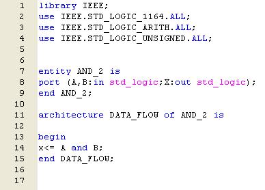
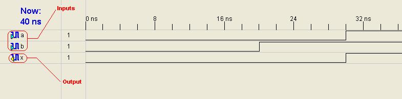
37 AND Gate simulation 37
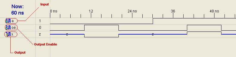
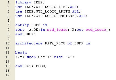
38 Passgate simulation 38
39 library ieee; use ieee.std_logic_1164.all; entity Full_Adder is -- generic (TS : TIME := 0.11 ns; TC : TIME := 0.1 ns); port (X, Y, Cin: in std_logic; Cout, Sum: out std_logic); end Full_Adder; architecture Concurrent of Full_Adder is begin Sum <= X xor Y xor Cin after 0.11 ns ; Cout <= (X and Y) or (X and Cin) or (Y and Cin) after 0.11 ns; end Concurrent; 39
40 What Synthesis Programs do? Synthesis programs are large packages that contain many algorithms for processing the VHDL Code, which generally include : Check the Syntax and Semantics of the Code Deduce the logic and state elements Optimize the technology independent functions (Boolean and State optimization) Map the optimized structure to the target technology (Place and Route) Evaluate the Structure performance ( Timing, Power and Area) Perform technology-dependent to obtain better final result. It is important to note that there is a different synthesis paths with different synthesis packages from different companies, And that not everything that can be simulated can be synthesized. You always have to refer to the synthesis packages to see the sequential construct or the module that you have selected is it synthesizable or not.
41 Points to watch for The way the code is written will greatly affect the size and speed of the synthesized circuit. For test bench, you may write unsenthesizable structures to test your circuit. Always use hierarchy, regularity, modularity and locality in your code. Insert comments to describe the variables and your construct. Write: date, author, name of the entity in the first line of your entity.
CSCI Lab 3. VHDL Syntax. Due: Tuesday, week6 Submit to: \\fs2\csci250\lab-3\
 CSCI 250 - Lab 3 VHDL Syntax Due: Tuesday, week6 Submit to: \\fs2\csci250\lab-3\ Objectives 1. Learn VHDL Valid Names 2. Learn the presentation of Assignment and Comments 3. Learn Modes, Types, Array,
Review of Digital Design with VHDL
 Review of Digital Design with VHDL Digital World Digital world is a world of 0 and 1 Each binary digit is called a bit Eight consecutive bits are called a byte Hexadecimal (base 16) representation for
EE 459/500 HDL Based Digital Design with Programmable Logic. Lecture 4 Introduction to VHDL
 EE 459/500 HDL Based Digital Design with Programmable Logic Lecture 4 Introduction to VHDL Read before class: Chapter 2 from textbook (first part) Outline VHDL Overview VHDL Characteristics and Concepts
ECE4401 / CSE3350 ECE280 / CSE280 Digital Design Laboratory
 ECE4401 / CSE3350 ECE280 / CSE280 Digital Design Laboratory Instructor John Chandy Office: ITEB 437 Office Hours: W10-12 Tel: (860) 486-5047 Email: john.chandy@uconn chandy@uconn.edu Class home page: HuskyCT
Lecture 3: Modeling in VHDL. EE 3610 Digital Systems
 EE 3610: Digital Systems 1 Lecture 3: Modeling in VHDL VHDL: Overview 2 VHDL VHSIC Hardware Description Language VHSIC=Very High Speed Integrated Circuit Programming language for modelling of hardware
Hardware Description Language VHDL (1) Introduction
 Introduction") Hardware Description Language VHDL (1) Introduction Digital Radiation Measurement and Spectroscopy NE/RHP 537 Introduction Hardware description language (HDL) Intended to describe circuits textually, for
Hardware Description Language VHDL (1) Introduction Digital Radiation Measurement and Spectroscopy NE/RHP 537 Introduction Hardware description language (HDL) Intended to describe circuits textually, for
Abi Farsoni, Department of Nuclear Engineering and Radiation Health Physics, Oregon State University
 Hardware description language (HDL) Intended to describe circuits textually, for a computer to read Evolved starting in the 1970s and 1980s Popular languages today include: VHDL Defined in 1980s by U.S.
Contents. Appendix D VHDL Summary Page 1 of 23
 Appendix D VHDL Summary Page 1 of 23 Contents Appendix D VHDL Summary...2 D.1 Basic Language Elements...2 D.1.1 Comments...2 D.1.2 Identifiers...2 D.1.3 Data Objects...2 D.1.4 Data Types...2 D.1.5 Data
EECE-4740/5740 Advanced VHDL and FPGA Design. Lecture 3 Concurrent and sequential statements
 EECE-4740/5740 Advanced VHDL and FPGA Design Lecture 3 Concurrent and sequential statements Cristinel Ababei Marquette University Department of Electrical and Computer Engineering Overview Components hierarchy
IT T35 Digital system desigm y - ii /s - iii
 UNIT - V Introduction to Verilog Hardware Description Language Introduction HDL for combinational circuits Sequential circuits Registers and counters HDL description for binary multiplier. 5.1 INTRODUCTION
COE 405 Design Methodology Based on VHDL
 COE 405 Design Methodology Based on VHDL Dr. Aiman H. El-Maleh Computer Engineering Department King Fahd University of Petroleum & Minerals Outline Elements of VHDL Top-Down Design Top-Down Design with
Digital Design with FPGAs. By Neeraj Kulkarni
 Digital Design with FPGAs By Neeraj Kulkarni Some Basic Electronics Basic Elements: Gates: And, Or, Nor, Nand, Xor.. Memory elements: Flip Flops, Registers.. Techniques to design a circuit using basic
Logic and Computer Design Fundamentals VHDL. Part 1 Chapter 4 Basics and Constructs
 Logic and Computer Design Fundamentals VHDL Part Chapter 4 Basics and Constructs Charles Kime & Thomas Kaminski 24 Pearson Education, Inc. Terms of Use (Hyperlinks are active in View Show mode) Overview
FPGA Design Challenge :Techkriti 14 Digital Design using Verilog Part 1
 FPGA Design Challenge :Techkriti 14 Digital Design using Verilog Part 1 Anurag Dwivedi Digital Design : Bottom Up Approach Basic Block - Gates Digital Design : Bottom Up Approach Gates -> Flip Flops Digital
Embedded Systems CS - ES
 Embedded Systems - 1 - REVIEW Hardware/System description languages VDHL VHDL-AMS SystemC TLM - 2 - VHDL REVIEW Main goal was modeling of digital circuits Modelling at various levels of abstraction Technology-independent
Lecture 3 Introduction to VHDL
 CPE 487: Digital System Design Spring 2018 Lecture 3 Introduction to VHDL Bryan Ackland Department of Electrical and Computer Engineering Stevens Institute of Technology Hoboken, NJ 07030 1 Managing Design
ENGIN 241 Digital Systems with Lab
 ENGIN 241 Digital Systems with Lab (4) Dr. Honggang Zhang Engineering Department University of Massachusetts Boston 1 Introduction Hardware description language (HDL): Specifies logic function only Computer-aided
Digital Design Using VHDL Using Xilinx s Tool for Synthesis and ModelSim for Verification
 Digital Design Using VHDL Using Xilinx s Tool for Synthesis and ModelSim for Verification Ahmed Abu-Hajar, Ph.D. abuhajar@digitavid.net Digitavid, Inc San Jose, CA Session One Outline Introducing VHDL
Basic Language Concepts
 Basic Language Concepts Sudhakar Yalamanchili, Georgia Institute of Technology ECE 4170 (1) Describing Design Entities a sum b carry Primary programming abstraction is a design entity Register, logic block,
Hardware Modeling. VHDL Syntax. Vienna University of Technology Department of Computer Engineering ECS Group
 Hardware Modeling VHDL Syntax Vienna University of Technology Department of Computer Engineering ECS Group Contents Identifiers Types & Attributes Operators Sequential Statements Subroutines 2 Identifiers
Lecture 1: VHDL Quick Start. Digital Systems Design. Fall 10, Dec 17 Lecture 1 1
 Lecture 1: VHDL Quick Start Digital Systems Design Fall 10, Dec 17 Lecture 1 1 Objective Quick introduction to VHDL basic language concepts basic design methodology Use The Student s Guide to VHDL or The
VHDL. Official Definition: VHSIC Hardware Description Language VHISC Very High Speed Integrated Circuit
 VHDL VHDL Official Definition: VHSIC Hardware Description Language VHISC Very High Speed Integrated Circuit VHDL Alternative (Student Generated) Definition Very Hard Digital Logic language VHDL Design
ECE U530 Digital Hardware Synthesis. Course Accounts and Tools
 ECE U530 Digital Hardware Synthesis Prof. Miriam Leeser mel@coe.neu.edu Sept 13, 2006 Lecture 3: Basic VHDL constructs Signals, Variables, Constants VHDL Simulator and Test benches Types Reading: Ashenden
VHDL Structural Modeling II
 VHDL Structural Modeling II ECE-331, Digital Design Prof. Hintz Electrical and Computer Engineering 5/7/2001 331_13 1 Ports and Their Usage Port Modes in reads a signal out writes a signal inout reads
VHDL. ELEC 418 Advanced Digital Systems Dr. Ron Hayne. Images Courtesy of Cengage Learning
 VHDL ELEC 418 Advanced Digital Systems Dr. Ron Hayne Images Courtesy of Cengage Learning Design Flow 418_02 2 VHDL Modules 418_02 3 VHDL Libraries library IEEE; use IEEE.std_logic_1164.all; std_logic Single-bit
Hardware description languages
 Specifying digital circuits Schematics (what we ve done so far) Structural description Describe circuit as interconnected elements Build complex circuits using hierarchy Large circuits are unreadable Hardware
Computer-Aided Digital System Design VHDL
 بس م اهلل الر حم ن الر حی م Iran University of Science and Technology Department of Computer Engineering Computer-Aided Digital System Design VHDL Ramin Rajaei ramin_rajaei@ee.sharif.edu Modeling Styles
VHDL. Douglas L. Perry. Third Edition
 VHDL Douglas L. Perry Third Edition McGraw-Hill New York San Francisco Washington, D.C. Auckland Bogota Caracas Lisbon London Madrid Mexico City Milan Montreal New Delhi San Juan Singapore Sydney Tokyo
Synthesis from VHDL. Krzysztof Kuchcinski Department of Computer Science Lund Institute of Technology Sweden
 Synthesis from VHDL Krzysztof Kuchcinski Krzysztof.Kuchcinski@cs.lth.se Department of Computer Science Lund Institute of Technology Sweden March 23, 2006 Kris Kuchcinski (LTH) Synthesis from VHDL March
CS211 Digital Systems/Lab. Introduction to VHDL. Hyotaek Shim, Computer Architecture Laboratory
 CS211 Digital Systems/Lab Introduction to VHDL Hyotaek Shim, Computer Architecture Laboratory Programmable Logic Device (PLD) 2/32 An electronic component used to build reconfigurable digital circuits
ECE 545 Lecture 5. Data Flow Modeling in VHDL. George Mason University
 ECE 545 Lecture 5 Data Flow Modeling in VHDL George Mason University Required reading P. Chu, RTL Hardware Design using VHDL Chapter 4, Concurrent Signal Assignment Statements of VHDL 2 Types of VHDL Description
ELCT 501: Digital System Design
 ELCT 501: Digital System Lecture 4: CAD tools (Continued) Dr. Mohamed Abd El Ghany, Basic VHDL Concept Via an Example Problem: write VHDL code for 1-bit adder 4-bit adder 2 1-bit adder Inputs: A (1 bit)
Concurrent Signal Assignment Statements (CSAs)
") Concurrent Signal Assignment Statements (CSAs) Digital systems operate with concurrent signals Signals are assigned values at a specific point in time. VHDL uses signal assignment statements Specify value
Concurrent Signal Assignment Statements (CSAs) Digital systems operate with concurrent signals Signals are assigned values at a specific point in time. VHDL uses signal assignment statements Specify value
!"#$%&&"'(')"*+"%,%-".#"'/"'.001$$"
*+%,%-.#'/'.001$$") !"#$%&&"'(')"*+"%,%-".#"'/"'.001$$"!!"#$%&'#()#*+"+#,-."/0110#230#4."50",+"+#)6# 6+-+#(.6+-0#)4475.8)60#0/#.65-0#230#9+**+"+# 2.48).-0#(.6+-0#! 2+"*5."5*:#,."/0110#;)**0! *),".6*:#-.99-0*0"5."+#2+660,.40"5)#;)*)2)#
!"#$%&&"'(')"*+"%,%-".#"'/"'.001$$"!!"#$%&'#()#*+"+#,-."/0110#230#4."50",+"+#)6# 6+-+#(.6+-0#)4475.8)60#0/#.65-0#230#9+**+"+# 2.48).-0#(.6+-0#! 2+"*5."5*:#,."/0110#;)**0! *),".6*:#-.99-0*0"5."+#2+660,.40"5)#;)*)2)#
ECE 3401 Lecture 10. More on VHDL
 ECE 3401 Lecture 10 More on VHDL Outline More on VHDL Some VHDL Basics Data Types Operators Delay Models VHDL for Simulation VHDL for Synthesis 1 Data Types Every signal has a type, type specifies possible
A Brief Introduction to Verilog Hardware Definition Language (HDL)
") www.realdigital.org A Brief Introduction to Verilog Hardware Definition Language (HDL) Forward Verilog is a Hardware Description language (HDL) that is used to define the structure and/or behavior of digital
www.realdigital.org A Brief Introduction to Verilog Hardware Definition Language (HDL) Forward Verilog is a Hardware Description language (HDL) that is used to define the structure and/or behavior of digital
VHDL BASIC ELEMENTS INTRODUCTION
 VHDL BASIC ELEMENTS INTRODUCTION VHDL Basic elements Identifiers Basic identifiers Extended identifiers Data Objects Constant Variable Signal File Data Types Scalar Composite Access File type Identifiers
Design units can NOT be split across different files
 Skeleton of a Basic VHDL Program This slide set covers the components to a basic VHDL program, including lexical elements, program format, data types and operators A VHDL program consists of a collection
A bird s eye view on VHDL!
 Advanced Topics on Heterogeneous System Architectures A bird s eye view on VHDL Politecnico di Milano Conference Room, Bld 20 19 November, 2015 Antonio R. Miele Marco D. Santambrogio Politecnico di Milano
Advanced Training Course on FPGA Design and VHDL for Hardware Simulation and Synthesis. 26 October - 20 November, 2009
 2065-15 Advanced Training Course on FPGA Design and VHDL for Hardware Simulation and Synthesis 26 October - 20 November, 2009 FPGA Architectures & VHDL Introduction to Synthesis Nizar Abdallah ACTEL Corp.2061
310/ ICTP-INFN Advanced Tranining Course on FPGA and VHDL for Hardware Simulation and Synthesis 27 November - 22 December 2006
 310/1780-10 ICTP-INFN Advanced Tranining Course on FPGA and VHDL for Hardware Simulation and Synthesis 27 November - 22 December 2006 VHDL & FPGA - Session 2 Nizar ABDALLH ACTEL Corp. 2061 Stierlin Court
Performance Engineering of Real-Time and Embedded Systems. Introduction to VHDL
 Performance Engineering of Real-Time and Embedded Systems Introduction to VHDL VHDL designs are decomposed into blocks. A block has an entity/architecture pair. Entity describes the interface Architecture
Lecture 4. VHDL Fundamentals. George Mason University
 Lecture 4 VHDL Fundamentals George Mason University Required reading P. Chu, RTL Hardware Design using VHDL Chapter 3, Basic Language Constructs of VHDL 2 Design Entity ECE 448 FPGA and ASIC Design with
VHDL 3 BASIC OPERATORS AND ARCHITECTURE BODY. Design descriptions & design constructions examples are taken from foundation series examples
 1 VHDL 3 BASIC OPERATORS AND ARCHITECTURE BODY Design descriptions & design constructions examples are taken from foundation series examples 2 What we have done in Lab 1 entity AND_Gate is port ( a : in
Verilog. What is Verilog? VHDL vs. Verilog. Hardware description language: Two major languages. Many EDA tools support HDL-based design
 Verilog What is Verilog? Hardware description language: Are used to describe digital system in text form Used for modeling, simulation, design Two major languages Verilog (IEEE 1364), latest version is
Declarations. Lexical elements. Type declaration Subtype declaration Constant declaration Signal declaration Variable declaration.
 Lexical elements Declarations Reserved words Type declaration Subtype declaration Constant declaration Signal declaration Variable declaration page 1 page 3 Type declaration Reserved words architecture
What is Verilog HDL? Lecture 1: Verilog HDL Introduction. Basic Design Methodology. What is VHDL? Requirements
 What is Verilog HDL? Lecture 1: Verilog HDL Introduction Verilog Hardware Description Language(HDL)? A high-level computer language can model, represent and simulate digital design Hardware concurrency
Libraries. Library ieee; Use ieee.std_logic_1164.all; Use ieee.std_logic_arith.all; Use ieee.std_logic_signed.all; Use ieee.std_logic_unsigned.
 VHDL Coding Basics Overview Chip Libraries Library ieee; Use ieee.std_logic_1164.all; Use ieee.std_logic_arith.all; Use ieee.std_logic_signed.all; Use ieee.std_logic_unsigned.all; Data Types bit values:
Digital Systems Design
 Digital Systems Design Review of Combinatorial Circuit Building Blocks: VHDL for Combinational Circuits Dr. D. J. Jackson Lecture 2-1 Introduction to VHDL Designer writes a logic circuit description in
Inthis lecture we will cover the following material:
 Lecture #8 Inthis lecture we will cover the following material: The standard package, The std_logic_1164 Concordia Objects & data Types (Signals, Variables, Constants, Literals, Character) Types and Subtypes
CDA 4253 FPGA System Design Introduction to VHDL. Hao Zheng Dept of Comp Sci & Eng USF
 CDA 4253 FPGA System Design Introduction to VHDL Hao Zheng Dept of Comp Sci & Eng USF Reading P. Chu, FPGA Prototyping by VHDL Examples Chapter 1, Gate-level combinational circuits Two purposes of using
ECE 448 Lecture 3. Combinational-Circuit Building Blocks. Data Flow Modeling of Combinational Logic
 ECE 448 Lecture 3 Combinational-Circuit Building Blocks Data Flow Modeling of Combinational Logic George Mason University Reading Required P. Chu, FPGA Prototyping by VHDL Examples Chapter 3, RT-level
What Is VHDL? VHSIC (Very High Speed Integrated Circuit) Hardware Description Language IEEE 1076 standard (1987, 1993)
 Hardware Description Language IEEE 1076 standard (1987, 1993)") What Is VHDL? VHSIC (Very High Speed Integrated Circuit) Hardware Description Language IEEE 1076 standard (1987, 1993) Only possible to synthesize logic from a subset of VHDL Subset varies according to
What Is VHDL? VHSIC (Very High Speed Integrated Circuit) Hardware Description Language IEEE 1076 standard (1987, 1993) Only possible to synthesize logic from a subset of VHDL Subset varies according to
Digital Design Using VHDL Using Xilinx s Tool for Synthesis and ModelSim for Verification Part II
 Digital Design Using VHDL Using Xilinx s Tool for Synthesis and ModelSim for Verification Part II Ahmed Abu-Hajar, Ph.D. abuhajar@digitavid.net Digitavid, Inc San Jose, CA VHDL Lexical Description Code
VHDL Lexical Elements
 1 Design File = Sequence of Lexical Elements && Separators (a) Separators: Any # of Separators Allowed Between Lexical Elements 1. Space character 2. Tab 3. Line Feed / Carriage Return (EOL) (b) Lexical
Speaker: Shao-Wei Feng Adviser: Prof. An-Yeu Wu Date: 2010/09/28
 99-1 Under-Graduate Project Verilog Simulation & Debugging Tools Speaker: Shao-Wei Feng Adviser: Prof. An-Yeu Wu Date: 2010/09/28 ACCESS IC LAB Outline Basic Concept of Verilog HDL Gate Level Modeling
Introduction to VHDL. Yvonne Avilés Colaboration: Irvin Ortiz Flores Rapid System Prototyping Laboratory (RASP) University of Puerto Rico at Mayaguez
 University of Puerto Rico at Mayaguez") Introduction to VHDL Yvonne Avilés Colaboration: Irvin Ortiz Flores Rapid System Prototyping Laboratory (RASP) University of Puerto Rico at Mayaguez What is VHDL? Very High Speed Integrated Circuit Hardware
Introduction to VHDL Yvonne Avilés Colaboration: Irvin Ortiz Flores Rapid System Prototyping Laboratory (RASP) University of Puerto Rico at Mayaguez What is VHDL? Very High Speed Integrated Circuit Hardware
Getting Started with VHDL
 Getting Started with VHDL VHDL code is composed of a number of entities Entities describe the interface of the component Entities can be primitive objects or complex objects Architectures are associated
EITF35: Introduction to Structured VLSI Design
 EITF35: Introduction to Structured VLSI Design Part 1.2.2: VHDL-1 Liang Liu liang.liu@eit.lth.se 1 Outline VHDL Background Basic VHDL Component An example FSM Design with VHDL Simulation & TestBench 2
IE1204 Digital Design L7: Combinational circuits, Introduction to VHDL
 IE24 Digital Design L7: Combinational circuits, Introduction to VHDL Elena Dubrova KTH / ICT / ES dubrova@kth.se This lecture BV 38-339, 6-65, 28-29,34-365 IE24 Digital Design, HT 24 2 The multiplexer
Introduction to VHDL. Main language concepts
 Introduction to VHDL VHSIC (Very High Speed Integrated Circuit) Hardware Description Language Current standard is IEEE 1076-1993 (VHDL-93). Some tools still only support VHDL-87. Tools used in the lab
BASIC VHDL LANGUAGE ELEMENTS AND SEMANTICS. Lecture 7 & 8 Dr. Tayab Din Memon
 BASIC VHDL LANGUAGE ELEMENTS AND SEMANTICS Lecture 7 & 8 Dr. Tayab Din Memon Outline Data Objects Data Types Operators Attributes VHDL Data Types VHDL Data Objects Signal Constant Variable File VHDL Data
Declarations of Components and Entities are similar Components are virtual design entities entity OR_3 is
 Reserved Words component OR_3 port (A,B,C: in bit; Z: out bit); end component ; Reserved Words Declarations of Components and Entities are similar Components are virtual design entities entity OR_3 is
ECE 448 Lecture 3. Combinational-Circuit Building Blocks. Data Flow Modeling of Combinational Logic
 ECE 448 Lecture 3 Combinational-Circuit Building Blocks Data Flow Modeling of Combinational Logic George Mason University Reading Required P. Chu, FPGA Prototyping by VHDL Examples Chapter 3, RT-level
Verilog Design Principles
 16 h7fex // 16-bit value, low order 4 bits unknown 8 bxx001100 // 8-bit value, most significant 2 bits unknown. 8 hzz // 8-bit value, all bits high impedance. Verilog Design Principles ECGR2181 Extra Notes
VHDL Part 2. What is on the agenda? Basic VHDL Constructs. Examples. Data types Objects Packages and libraries Attributes Predefined operators
 VHDL Part 2 Some of the slides are taken from http://www.ece.uah.edu/~milenka/cpe428-02s/ What is on the agenda? Basic VHDL Constructs Data types Objects Packages and libraries Attributes Predefined operators
Contents. Appendix D Verilog Summary Page 1 of 16
 Appix D Verilog Summary Page 1 of 16 Contents Appix D Verilog Summary... 2 D.1 Basic Language Elements... 2 D.1.1 Keywords... 2 D.1.2 Comments... 2 D.1.3 Identifiers... 2 D.1.4 Numbers and Strings... 3
Outline CPE 626. Advanced VLSI Design. Lecture 4: VHDL Recapitulation (Part 2) Signals. Variables. Constants. Variables vs.
 Signals. Variables. Constants. Variables vs.") CPE 626 Lecture 4: VHDL Recapitulation (Part 2) Aleksandar Milenkovic http://www.ece.uah.edu/~milenka http://www.ece.uah.edu/~milenka/cpe626-04f/ milenka@ece.uah.edu Assistant Professor Electrical and
CPE 626 Lecture 4: VHDL Recapitulation (Part 2) Aleksandar Milenkovic http://www.ece.uah.edu/~milenka http://www.ece.uah.edu/~milenka/cpe626-04f/ milenka@ece.uah.edu Assistant Professor Electrical and
14:332:231 DIGITAL LOGIC DESIGN. Hardware Description Languages
 14:332:231 DIGITAL LOGIC DESIGN Ivan Marsic, Rutgers University Electrical & Computer Engineering Fall 2013 Lecture #22: Introduction to Verilog Hardware Description Languages Basic idea: Language constructs
ECOM4311 Digital Systems Design
 ECOM 4311 Digital Systems Design Eng. Monther Abusultan Computer Engineering Dept. Islamic University of Gaza Page 1 Agenda 1. VHDL : Data Types Cont d 2. VHDL : Operators 3. VHDL : Signal Assignments
2/14/2016. Hardware Synthesis. Midia Reshadi. CE Department. Entities, Architectures, and Coding.
 Hardware Synthesis MidiaReshadi CE Department Science and research branch of Islamic Azad University Email: ce.srbiau@gmail.com Midia Reshadi 1 Chapter 2 Entities, Architectures, and Coding Styles Midia
JUNE, JULY 2013 Fundamentals of HDL (10EC45) PART A
 PART A") JUNE, JULY 2013 Fundamentals of HDL (10EC45) Time: 3hrs Max Marks:100 Note: Answer FIVE full questions, selecting at least TWO questions from each part. PART A Q1.a. Describe VHDL scalar data types with
JUNE, JULY 2013 Fundamentals of HDL (10EC45) Time: 3hrs Max Marks:100 Note: Answer FIVE full questions, selecting at least TWO questions from each part. PART A Q1.a. Describe VHDL scalar data types with
Verilog HDL is one of the two most common Hardware Description Languages (HDL) used by integrated circuit (IC) designers. The other one is VHDL.
 used by integrated circuit (IC) designers. The other one is VHDL.") Verilog HDL is one of the two most common Hardware Description Languages (HDL) used by integrated circuit (IC) designers. The other one is VHDL. HDL s allows the design to be simulated earlier in the design
Verilog HDL is one of the two most common Hardware Description Languages (HDL) used by integrated circuit (IC) designers. The other one is VHDL. HDL s allows the design to be simulated earlier in the design
FPGA: FIELD PROGRAMMABLE GATE ARRAY Verilog: a hardware description language. Reference: [1]
![FPGA: FIELD PROGRAMMABLE GATE ARRAY Verilog: a hardware description language. Reference: [1]](/thumbs/80/81661285.jpg "FPGA: FIELD PROGRAMMABLE GATE ARRAY Verilog: a hardware description language. Reference: [1]") FPGA: FIELD PROGRAMMABLE GATE ARRAY Verilog: a hardware description language Reference: [] FIELD PROGRAMMABLE GATE ARRAY FPGA is a hardware logic device that is programmable Logic functions may be programmed
FPGA: FIELD PROGRAMMABLE GATE ARRAY Verilog: a hardware description language Reference: [] FIELD PROGRAMMABLE GATE ARRAY FPGA is a hardware logic device that is programmable Logic functions may be programmed
VHDL. Chapter 1 Introduction to VHDL. Course Objectives Affected. Outline
 Chapter 1 Introduction to VHDL VHDL VHDL - Flaxer Eli Ch 1-1 Course Objectives Affected Write functionally correct and well-documented VHDL code, intended for either simulation or synthesis, of any combinational
VHDL: A Crash Course
 VHDL: A Crash Course Dr. Manuel Jiménez With contributions by: Irvin Ortiz Flores Electrical and Computer Engineering Department University of Puerto Rico - Mayaguez Outline Background Program Structure
Synthesis of Combinational and Sequential Circuits with Verilog
 Synthesis of Combinational and Sequential Circuits with Verilog What is Verilog? Hardware description language: Are used to describe digital system in text form Used for modeling, simulation, design Two
5. VHDL - Introduction - 5. VHDL - Design flow - 5. VHDL - Entities and Architectures (1) - 5. VHDL - Entities and Architectures (2) -
 - 5. VHDL - Entities and Architectures (2) -") Sistemas Digitais I LESI - 2º ano Lesson 5 - VHDL Prof. João Miguel Fernandes (miguel@di.uminho.pt) Dept. Informática - Introduction - VHDL was developed, in the mid-1980s, by DoD and IEEE. VHDL stands
Sistemas Digitais I LESI - 2º ano Lesson 5 - VHDL Prof. João Miguel Fernandes (miguel@di.uminho.pt) Dept. Informática - Introduction - VHDL was developed, in the mid-1980s, by DoD and IEEE. VHDL stands
101-1 Under-Graduate Project Digital IC Design Flow
 101-1 Under-Graduate Project Digital IC Design Flow Speaker: Ming-Chun Hsiao Adviser: Prof. An-Yeu Wu Date: 2012/9/25 ACCESS IC LAB Outline Introduction to Integrated Circuit IC Design Flow Verilog HDL
EEL 4783: Hardware/Software Co-design with FPGAs
 EEL 4783: Hardware/Software Co-design with FPGAs Lecture 9: Short Introduction to VHDL* Prof. Mingjie Lin * Beased on notes of Turfts lecture 1 What does HDL stand for? HDL is short for Hardware Description
VHDL for Complex Designs
 ELEC 379 : DESIGN OF DIGITAL AND MICROCOMPUTER SYSTEMS 1998/99 WINTER SESSION, TERM 2 VHDL for Complex Designs This lecture covers VHDL features that are useful when designing complex logic circuits. After
Outline. CPE/EE 422/522 Advanced Logic Design L07. Review: JK Flip-Flop Model. Review: VHDL Program Structure. Review: VHDL Models for a MUX
 Outline CPE/EE 422/522 Advanced Logic Design L07 Electrical and Computer Engineering University of Alabama in Huntsville What we know How to model Combinational Networks in VHDL Structural, Dataflow, Behavioral
Verilog Fundamentals. Shubham Singh. Junior Undergrad. Electrical Engineering
 Verilog Fundamentals Shubham Singh Junior Undergrad. Electrical Engineering VERILOG FUNDAMENTALS HDLs HISTORY HOW FPGA & VERILOG ARE RELATED CODING IN VERILOG HDLs HISTORY HDL HARDWARE DESCRIPTION LANGUAGE
CPE/EE 422/522. Chapter 8 - Additional Topics in VHDL. Dr. Rhonda Kay Gaede UAH. 8.1 Attributes - Signal Attributes that return a value
 CPE/EE 422/522 Chapter 8 - Additional Topics in VHDL Dr. Rhonda Kay Gaede UAH 1 8.1 Attributes - Signal Attributes that return a value A event true if a has just occurred A active true if A has, even if
This Lecture. Some components (useful for the homework) Verilog HDL (will continue next lecture)
 Verilog HDL (will continue next lecture)") Last Lecture The basic component of a digital circuit is the MOS transistor Transistor have instrinsic resistance and capacitance, so voltage values in the circuit take some time to change ( delay ) There
Last Lecture The basic component of a digital circuit is the MOS transistor Transistor have instrinsic resistance and capacitance, so voltage values in the circuit take some time to change ( delay ) There
A Verilog Primer. An Overview of Verilog for Digital Design and Simulation
 A Verilog Primer An Overview of Verilog for Digital Design and Simulation John Wright Vighnesh Iyer Department of Electrical Engineering and Computer Sciences College of Engineering, University of California,
Verilog Design Principles
 16 h7fex // 16-bit value, low order 4 bits unknown 8 bxx001100 // 8-bit value, most significant 2 bits unknown. 8 hzz // 8-bit value, all bits high impedance. Verilog Design Principles ECGR2181 Extra Notes
Combinational Logic COMB. LOGIC BLOCK. A Combinational Logic Block is one where the outputs depend only on the current inputs
 Combinational Logic A Combinational Logic Block is one where the outputs depend only on the current inputs COMB. LOGIC BLOCK A combinational logic block can be implemented using simple gates or lookup
Introduction to the VHDL language. VLSI Digital Design
 Introduction to the VHDL Hardware description language 1. Introduction 2. Basic elements 3. Scalar data types 4. Composed data types 5. Basic constructs (system definition) 6. Data flow description level
Introduction to Verilog
 Introduction to Verilog COE 202 Digital Logic Design Dr. Muhamed Mudawar King Fahd University of Petroleum and Minerals Presentation Outline Hardware Description Language Logic Simulation versus Synthesis
Mridula Allani Fall Fall
 Mridula Allani Fall 2010 Fall 2010 1 Model and document digital systems Hierarchical models System, RTL (Register Transfer Level), gates Different levels of abstraction Behavior, structure Verify circuit/system
INTRODUCTION TO VHDL. Lecture 5 & 6 Dr. Tayab Din Memon Assistant Professor Department of Electronic Engineering, MUET
 INTRODUCTION TO VHDL Lecture 5 & 6 Dr. Tayab Din Memon Assistant Professor Department of Electronic Engineering, MUET VHDL Resources Other Sources manufacturers web pages http://www.xilinx.com http://www.altera.com
Synthesizable Verilog
 Synthesizable Verilog Courtesy of Dr. Edwards@Columbia, and Dr. Franzon@NCSU http://csce.uark.edu +1 (479) 575-6043 yrpeng@uark.edu Design Methodology Structure and Function (Behavior) of a Design HDL
HDL. Hardware Description Languages extensively used for:
 HDL Hardware Description Languages extensively used for: Describing (digital) hardware (formal documentation) Simulating it Verifying it Synthesizing it (first step of modern design flow) 2 main options:
UNIT I Introduction to VHDL VHDL: - V -VHSIC, H - Hardware, D - Description, L Language Fundamental section of a basic VHDL code Library :
 UNIT I Introduction to VHDL VHDL stands for very high-speed integrated circuit hardware description language. Which is one of the programming languages used to model a digital system by dataflow, behavioral
Lecture 4. VHDL Fundamentals. Required reading. Example: NAND Gate. Design Entity. Example VHDL Code. Design Entity
 Required reading Lecture 4 VHDL Fundamentals P. Chu, RTL Hardware Design using VHDL Chapter 3, Basic Language Constructs of VHDL George Mason University 2 Example: NAND Gate Design Entity a b z a b z 0
Hardware Design Environments. Dr. Mahdi Abbasi Computer Engineering Department Bu-Ali Sina University
 Hardware Design Environments Dr. Mahdi Abbasi Computer Engineering Department Bu-Ali Sina University Outline Welcome to COE 405 Digital System Design Design Domains and Levels of Abstractions Synthesis
VLSI DESIGN (ELECTIVE-I) Question Bank Unit I
 Question Bank Unit I") VLSI DESIGN (ELECTIVE-I) Question Bank Unit I B.E (E&C) NOV-DEC 2008 1) If A & B are two unsigned variables, with A = 1100 and B = 1001, find the values of following expressions. i. (A and B) ii. (A ^
VLSI DESIGN (ELECTIVE-I) Question Bank Unit I B.E (E&C) NOV-DEC 2008 1) If A & B are two unsigned variables, with A = 1100 and B = 1001, find the values of following expressions. i. (A and B) ii. (A ^
Hardware Synthesis. References
 Hardware Synthesis MidiaReshadi CE Department Science and research branch of Islamic Azad University Email: ce.srbiau@gmail.com 1 References 2 1 Chapter 1 Digital Design Using VHDL and PLDs 3 Some Definitions
Sequential VHDL. Katarzyna Radecka. DSD COEN 313
 Sequential VHDL Katarzyna Radecka DSD COEN 313 kasiar@ece.concordia.ca Overview Process Sensitivity List Wait Statements If Statements Case Statements Loop Statements Three Styles of VHDL Behavioral Structural