תכן חומרה בשפת VERILOG הפקולטה להנדסה
|
|
|
- Elvin Thompson
- 5 years ago
- Views:
Transcription
1 תכן חומרה בשפת VERILOG סמסטר ב' תשע"ג משה דורון מרצה: מתרגלים: אריאל בורג, חג'ג' חן הפקולטה להנדסה 1
2 Course Topics - Outline Lecture 1 - Introduction Lecture 2 - Lexical conventions Lecture 3 - Data types Lecture 4 - Operators Lecture 5 - Behavioral modeling Lecture 6 - Data flow modeling Lecture 7 - Gate Level modeling Lecture 8 - Tasks and Functions Lecture 9 - Advanced Modeling Techniques Lecture 10 - System Tasks and Compiler directives Lecture 11 - Switch Level modeling Lecture 12 - Coding Styles and Test Benches Lecture 13 - Synthesis issues 2
3 3 Lecture 1 - Introduction Course Objectives Evolution of CAD What is HDL What is Verilog Verilog History Design Advantages Language Capabilities Levels of Abstraction Design Flow Design Methodologies Basic Unit module Structural Hierarchy Description Style Module Ports Module Instantiation Exercise 1
4 Course Objectives Gain thorough understanding of the essential concepts and capabilities of Verilog HW Description Language Gain practical experience in writing Verilog code for Hardware Systems Design, Verification and Synthesis Participants will be able to approach their Verilogbased Digital Design Projects with confidence 4
5 Evolution of EDA Over 30 years, Integrated Circuits (ICs) scaled up in complexity from hundreds gates to millions gates Electronic Design Automation (EDA) techniques evolved, enabling Chip Designers to cope with the ever increasing design complexity Today, EDA support HW Design Languages, Behavioral Simulation, Functional Verification, Synthesis to Gate- Level Netlist and Automatic ICs Placement and Routing During last 4 years, the hot trend is High Level Synthesis 5
6 What is Hardware Description Language (HDL) A convenient, powerful, Device-independent representation of Digital Logic (Behavior and Structure) Boosts Design Methodology: Functionality can be verified early in the design process. Simulation at a higher level, enable architectural evaluation and decisions. Coupling HDL Compiler with Logic Synthesis tools, automatically converts a Technology-independent HDL Design description and Functionality to a Gate-Level implementation, in different target Technologies. 6
7 7 What is Verilog One of the two major HDLs used by Hardware Designers in Industry and Academia. Ada-like VHDL is the other one Advantages: C- based Syntax, easy to master and use Condensed and efficient code Intensively used by Israeli Hi-Tech Industry Disadvantage: Poor constructs self-checking
8 Verilog History 1985: Introduced as Hardware modeling language by Gateway Design System 1990: Cadence acquired Gateway and became the language owner 1995: Verilog became an IEEE Standard 1364 Verilog 2001 fixed lot of Verilog 1995 problems 8
9 9 Verilog Design Advantages Single Language for Design & Simulation Increased ability to work with massive HW design HW documentation, Design reuse Verilog Simulator Tools allow you to perform the following tasks in the design process without building a Hardware Prototype: - Determine the feasibility of new design ideas - Try more than one approach to a design problem - Verify Functionality - Identify Design Problems
10 Language Capabilities Design can be described in a wide range of levels: Switch, Gate, Register Transfer Level (RTL), Algorithmic Design can be modeled in a mixed style Behavioral, Dataflow and Structural At the Behavioral level, Design can be described in RTL, Architecture and Algorithmic levels Hierarchical design can be described, up to any level, using the module instantiation construct A design can be of arbitrary size. No limit imposed 10
11 Language Capabilities (2) Two data types: net (wire) & variable (reg - abstract data storage element) Primitive Logic Gates and Switch-Level Gates, are built-in Language used for Test Bench - Stimuli & Monitor results Flexibility of creating a Combinational or Sequential, User Defined Primitive (UDP) Programming Language Interface (PLI), allow foreign functions access Verilog module info enables Designer s interaction with the Simulator 11
12 12 Levels of Abstraction Verilog is a High-level Language, having constructs supporting various Design s Abstraction Levels: (Top-to-Bottom) Behavioral - A module is implemented in terms of desired algorithm, without knowing the HW implementation details. Data Flow- A module is designed by specifying the data flow between registers and how data is a processed. (RTL) Gate Level- A module is implemented in terms of logic gates and the interconnections between them. Switch Level- A module is implemented in terms of switches (transistors), storage nodes, resistors and the interconnections between them.
13 Design Flow using Verilog Specification Architecture Design Coding in Verilog Simulation & Verification Compilation Function/Performance Definition Structure and Function (Behavior) of the Design Efficient, well-documented coding Design Behave as Required? Timing: Waveform Behavior HDL description into Netlist 13 Synthesis Mapping Logic Optimization Mapping Verified Design to target HW - FPGA or ASIC
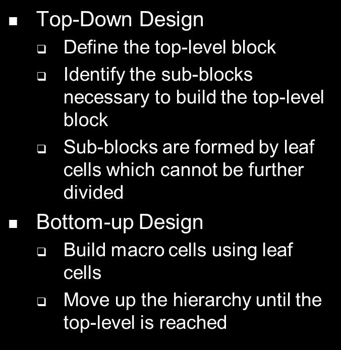
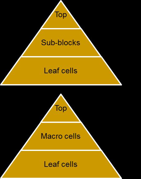

14 14 Design Methodologies
15 Basic Unit The Module Verilog describes a digital system as a set of modules Element or a collection of lower level design blocks A module can be instantiated in another module Each module has an interface and contents description Modules communicate externally with input, output and bi-directional ports 15
16 16 Module Structure module module_name (port_list) ; declarations: port declaration (input, output, inout, ) data type declaration (reg, wire, parameter, ) task and function declaration statements: initial block always block Behavioral module instantiation gate instantiation Structural UDP instantiation continuous assignment Data-flow endmodule
17 Example - AND module (data flow & behavioral) module AND (out, in1, in2) ; // <module name> <ports list> input in1, in2 ; output wire out ; assign out = in1 & in2 ; // data flow - continuous Assignment endmodule in1 out in2 module AND (out, in1, in2) ; // <module name> <ports list> input in1, in2 ; output reg out ; // must be reg type when used as LHS in an always block in1 or in2) // always block (sensitivity list) - behavioral out = in1 & in2 ; /* statements inside always block are executed only when one or more signals in the list changes value */ endmodule 17
18 Example - NAND (gate level) module a b nand q module Nand (q, a, b) ; // <module name> <ports list> output q ; input a, b ; endmodule nand (q, a, b) ; // Language gate primitive 18
19 Example D_FF (behavioral) module module D_FF(clk, nrst, d, q) ; input clk, nrst, d ; output reg q ; clk or negedge nrst) if (!nrst) q <= 0 ; else q <= d ; endmodule 19 d q clk nrst // Event-based Timing Control // reset state // normal operation
20 Structural Hierarchy Description Style Direct instantiation and connections of modules from a separate calling module - From the structural hierarchy of the design A module may be declared anywhere in a design relative to where it is called Signals in the higher calling module, are connected to signals in the lower called module by either: - Named association - Positional association 20
21 Module interconnections: Ports Within a Verilog system model, module interconnections occur at two levels: Peer to peer: modules interconnect with each other: Module A Module B Hierarchical: one module incorporates the other: Module A Module B 21
22 22 Module Ports Ports provide interface for the module to communicate with its environment. Declaration: <Port direction> <width> <port_name> ; Port direction can be input, output or inout. Example: module my_module (my_input_port, my_inout_port, my_output_port ) ; input [4:0] my_input_port ; inout my_inout_port ; output wire (or reg) [14:0] my_output_port ; endmodule
23 Port Specifications An input port specifies an internal name for a vector or scalar, driven by external entity. An output port specifies an internal name for a vector or scalar, driven by internal entity, available external to the module. An inout port specifies an internal name for a vector or scalar driven either by an internal or external entity. bi-directional Input or inout port cannot be declared as of type register. Port is always considered as net, unless declared elsewhere as reg (only for output port) 23
24 Correct Port Connection net net inout reg or net net input reg or net output net module 24
25 25 Module Instantiation - Port connections Ports of the instances could be connected by name or by order list. For small # of ports, connect by order list, else, by name. module fa_tb ; module FA4 (sum, cout, a, b, cin) ; reg [3:0] A, B ; output wire [3:0] sum ; reg CIN ; output wire cout ; wire [3:0] SUM ; input [3:0] a, b ; wire COUT ; input cin ; endmodule endmodule // Instantiate/connect by Positional association (order list): FA4 fa_byorder (SUM, COUT, A, B, CIN) ; // Instantiate/connect by Named association (port name): FA4 fa_byname (cout(cout),.sum(sum),.b(b),.cin(cin),.a(a) ;
26 Test Bench and UUT Instantiation Module Test Bench incorporates, hierarchically, the Unit Under Test (UUT) module Stimuli Unit Under Test Monitor registers inputs wires outputs wires, regs wires 26
27 27 D_FF Test Bench `include D_FF.v" // include the UUT Verilog file for simulator parsing `timescale 1ns / 100ps /* compiler directive. sets simulation s time unit and precision */ module D_FF_tb () ; reg Clk, Nrst, D ; // Stimuli signals wire Q ; // Monitor signal D_FF UUT(Clk, Nrst, D, Q) ; // instantiation of the D_FF (UUT) initial begin Clk = 1'b0; Nrst = 1'b0, D = 1'b0 ; // System monitoring function $monitor($time,"clk=%b,nrst=%b,d=%b;q=%b",clk,nrst,d,q) ; end always #1 Clk = ~Clk ; // Clock declaration initial begin #2 Nrst = 1'b1 ; // Out of reset #2 D = 1'b1 ; #2 $finish ; // System function - end simulation run end endmodule
28 General Info תרגולי מעבדה מקומות ישיבה קבועים במעבדה השתתפות חובה ב- 10 מתוך 13 תרגולי מעבדה ציון ציון הקורס ייקבע ע"י ממוצע מיטב ביצועי 10 מעבדות ספרים בספריה Verilog HDL: A Guide to Digital Design and Synthesis Design Through Verilog HDL A Verilog HDL Primer Digital VLSI Design with Verilog ספרות 28
29 29 Exercise 1 4bit Counter 4bit Binary Counter cntr_4b.v Test Bench for the Counter cntr_4b_tb.v Synchronous or Asynchronous Reset Up/Down Counter Decimal Counter - Counts from 0 to 9 Programmable Divider - Preloaded Counter Notes: - Use Notepad++ to write the Verilog code - Use Cadence Incisive Unified Simulator (IUS)
101-1 Under-Graduate Project Digital IC Design Flow
 101-1 Under-Graduate Project Digital IC Design Flow Speaker: Ming-Chun Hsiao Adviser: Prof. An-Yeu Wu Date: 2012/9/25 ACCESS IC LAB Outline Introduction to Integrated Circuit IC Design Flow Verilog HDL
Verilog. What is Verilog? VHDL vs. Verilog. Hardware description language: Two major languages. Many EDA tools support HDL-based design
 Verilog What is Verilog? Hardware description language: Are used to describe digital system in text form Used for modeling, simulation, design Two major languages Verilog (IEEE 1364), latest version is
VLSI II E. Özgür ATES
 VERILOG TUTORIAL VLSI II E. Özgür ATES Outline Introduction Language elements Gate-level modeling Data-flow modeling Behavioral modeling Modeling examples Simulation and test bench Hardware Description
Introduction to Verilog HDL
 Introduction to Verilog HDL Ben Abdallah Abderazek National University of Electro-communications, Tokyo, Graduate School of information Systems May 2004 04/09/08 1 What you will understand after having
FPGA Design Challenge :Techkriti 14 Digital Design using Verilog Part 1
 FPGA Design Challenge :Techkriti 14 Digital Design using Verilog Part 1 Anurag Dwivedi Digital Design : Bottom Up Approach Basic Block - Gates Digital Design : Bottom Up Approach Gates -> Flip Flops Digital
Synthesizable Verilog
 Synthesizable Verilog Courtesy of Dr. Edwards@Columbia, and Dr. Franzon@NCSU http://csce.uark.edu +1 (479) 575-6043 yrpeng@uark.edu Design Methodology Structure and Function (Behavior) of a Design HDL
ECE 2300 Digital Logic & Computer Organization. More Sequential Logic Verilog
 ECE 2300 Digital Logic & Computer Organization Spring 2018 More Sequential Logic Verilog Lecture 7: 1 Announcements HW3 will be posted tonight Prelim 1 Thursday March 1, in class Coverage: Lectures 1~7
Chap 6 Introduction to HDL (d)
") Design with Verilog Chap 6 Introduction to HDL (d) Credit to: MD Rizal Othman Faculty of Electrical & Electronics Engineering Universiti Malaysia Pahang Ext: 6036 VERILOG HDL Basic Unit A module Module
Design with Verilog Chap 6 Introduction to HDL (d) Credit to: MD Rizal Othman Faculty of Electrical & Electronics Engineering Universiti Malaysia Pahang Ext: 6036 VERILOG HDL Basic Unit A module Module
VHDL VS VERILOG.
 1 VHDL VS VERILOG http://www.cse.cuhk.edu.hk/~mcyang/teaching.html 2 VHDL & Verilog They are both hardware description languages for modeling hardware. They are each a notation to describe the behavioral
Synthesis of Combinational and Sequential Circuits with Verilog
 Synthesis of Combinational and Sequential Circuits with Verilog What is Verilog? Hardware description language: Are used to describe digital system in text form Used for modeling, simulation, design Two
Introduction to Verilog
 Introduction to Verilog COE 202 Digital Logic Design Dr. Muhamed Mudawar King Fahd University of Petroleum and Minerals Presentation Outline Hardware Description Language Logic Simulation versus Synthesis
A Brief Introduction to Verilog Hardware Definition Language (HDL)
") www.realdigital.org A Brief Introduction to Verilog Hardware Definition Language (HDL) Forward Verilog is a Hardware Description language (HDL) that is used to define the structure and/or behavior of digital
www.realdigital.org A Brief Introduction to Verilog Hardware Definition Language (HDL) Forward Verilog is a Hardware Description language (HDL) that is used to define the structure and/or behavior of digital
RTL Coding General Concepts
 RTL Coding General Concepts Typical Digital System 2 Components of a Digital System Printed circuit board (PCB) Embedded d software microprocessor microcontroller digital signal processor (DSP) ASIC Programmable
Spiral 1 / Unit 4 Verilog HDL. Digital Circuit Design Steps. Digital Circuit Design OVERVIEW. Mark Redekopp. Description. Verification.
 1-4.1 1-4.2 Spiral 1 / Unit 4 Verilog HDL Mark Redekopp OVERVIEW 1-4.3 1-4.4 Digital Circuit Design Steps Digital Circuit Design Description Design and computer-entry of circuit Verification Input Stimulus
Hardware Design Environments. Dr. Mahdi Abbasi Computer Engineering Department Bu-Ali Sina University
 Hardware Design Environments Dr. Mahdi Abbasi Computer Engineering Department Bu-Ali Sina University Outline Welcome to COE 405 Digital System Design Design Domains and Levels of Abstractions Synthesis
Introduction to Verilog HDL. Verilog 1
 Introduction to HDL Hardware Description Language (HDL) High-Level Programming Language Special constructs to model microelectronic circuits Describe the operation of a circuit at various levels of abstraction
Verilog Design Principles
 16 h7fex // 16-bit value, low order 4 bits unknown 8 bxx001100 // 8-bit value, most significant 2 bits unknown. 8 hzz // 8-bit value, all bits high impedance. Verilog Design Principles ECGR2181 Extra Notes
Tutorial on VHDL and Verilog Applications
 Second LACCEI International Latin American and Caribbean Conference for Engineering and Technology (LACCEI 2004) Challenges and Opportunities for Engineering Education, Research and Development 2-4 June
Verilog Design Principles
 16 h7fex // 16-bit value, low order 4 bits unknown 8 bxx001100 // 8-bit value, most significant 2 bits unknown. 8 hzz // 8-bit value, all bits high impedance. Verilog Design Principles ECGR2181 Extra Notes
What is Verilog HDL? Lecture 1: Verilog HDL Introduction. Basic Design Methodology. What is VHDL? Requirements
 What is Verilog HDL? Lecture 1: Verilog HDL Introduction Verilog Hardware Description Language(HDL)? A high-level computer language can model, represent and simulate digital design Hardware concurrency
ENGN1640: Design of Computing Systems Topic 02: Design/Lab Foundations
 ENGN1640: Design of Computing Systems Topic 02: Design/Lab Foundations Professor Sherief Reda http://scale.engin.brown.edu School of Engineering Brown University Spring 2017 1 Topics 1. Programmable logic
A Verilog Primer. An Overview of Verilog for Digital Design and Simulation
 A Verilog Primer An Overview of Verilog for Digital Design and Simulation John Wright Vighnesh Iyer Department of Electrical Engineering and Computer Sciences College of Engineering, University of California,
CAD for VLSI Design - I. Lecture 21 V. Kamakoti and Shankar Balachandran
 CAD for VLSI Design - I Lecture 21 V. Kamakoti and Shankar Balachandran Overview of this Lecture Understanding the process of Logic synthesis Logic Synthesis of HDL constructs Logic Synthesis What is this?
Lecture 15: System Modeling and Verilog
 Lecture 15: System Modeling and Verilog Slides courtesy of Deming Chen Intro. VLSI System Design Outline Outline Modeling Digital Systems Introduction to Verilog HDL Use of Verilog HDL in Synthesis Reading
Digital System Design Lecture 2: Design. Amir Masoud Gharehbaghi
 Digital System Design Lecture 2: Design Amir Masoud Gharehbaghi amgh@mehr.sharif.edu Table of Contents Design Methodologies Overview of IC Design Flow Hardware Description Languages Brief History of HDLs
Digital Design with FPGAs. By Neeraj Kulkarni
 Digital Design with FPGAs By Neeraj Kulkarni Some Basic Electronics Basic Elements: Gates: And, Or, Nor, Nand, Xor.. Memory elements: Flip Flops, Registers.. Techniques to design a circuit using basic
EECS150 - Digital Design Lecture 5 - Verilog Logic Synthesis
 EECS150 - Digital Design Lecture 5 - Verilog Logic Synthesis Jan 31, 2012 John Wawrzynek Spring 2012 EECS150 - Lec05-verilog_synth Page 1 Outline Quick review of essentials of state elements Finite State
Computer Aided Design Basic Syntax Gate Level Modeling Behavioral Modeling. Verilog
 Verilog Radek Pelánek and Šimon Řeřucha Contents 1 Computer Aided Design 2 Basic Syntax 3 Gate Level Modeling 4 Behavioral Modeling Computer Aided Design Hardware Description Languages (HDL) Verilog C
Verilog HDL [As per Choice Based Credit System (CBCS) scheme]
![Verilog HDL [As per Choice Based Credit System (CBCS) scheme]](/thumbs/89/100794459.jpg "Verilog HDL [As per Choice Based Credit System (CBCS) scheme]") Verilog HDL [As per Choice Based Credit System (CBCS) scheme] Subject Code IA Marks 20 Number of Lecture 04 Exam Marks 80 Hours/Week Total Number of 50 (10 Hours / Module) Exam Hours 03 Lecture Hours CREDITS
Verilog HDL [As per Choice Based Credit System (CBCS) scheme] Subject Code IA Marks 20 Number of Lecture 04 Exam Marks 80 Hours/Week Total Number of 50 (10 Hours / Module) Exam Hours 03 Lecture Hours CREDITS
LSN 1 Digital Design Flow for PLDs
 LSN 1 Digital Design Flow for PLDs ECT357 Microprocessors I Department of Engineering Technology LSN 1 Programmable Logic Devices Functionless devices in base form Require programming to operate The logic
EN2911X: Reconfigurable Computing Topic 02: Hardware Definition Languages
 EN2911X: Reconfigurable Computing Topic 02: Hardware Definition Languages Professor Sherief Reda http://scale.engin.brown.edu School of Engineering Brown University Spring 2014 1 Introduction to Verilog
ENGN1640: Design of Computing Systems Topic 02: Design/Lab Foundations
 ENGN1640: Design of Computing Systems Topic 02: Design/Lab Foundations Professor Sherief Reda http://scale.engin.brown.edu School of Engineering Brown University Spring 2016 1 Topics 1. Programmable logic
P-1/26. Samir Palnitkar. Prentice-Hall, Inc. INSTRUCTOR : CHING-LUNG SU.
 : P-1/26 Textbook: Verilog HDL 2 nd. Edition Samir Palnitkar Prentice-Hall, Inc. : INSTRUCTOR : CHING-LUNG SU E-mail: kevinsu@yuntech.edu.tw Chapter 4 P-2/26 Chapter 4 Modules and Outline of Chapter 4
EECS150 - Digital Design Lecture 10 Logic Synthesis
 EECS150 - Digital Design Lecture 10 Logic Synthesis September 26, 2002 John Wawrzynek Fall 2002 EECS150 Lec10-synthesis Page 1 Logic Synthesis Verilog and VHDL stated out as simulation languages, but quickly
St.MARTIN S ENGINEERING COLLEGE Dhulapally, Secunderabad
 St.MARTIN S ENGINEERING COLLEGE Dhulapally, Secunderabad-500 014 Subject: Digital Design Using Verilog Hdl Class : ECE-II Group A (Short Answer Questions) UNIT-I 1 Define verilog HDL? 2 List levels of
EECS150 - Digital Design Lecture 10 Logic Synthesis
 EECS150 - Digital Design Lecture 10 Logic Synthesis February 13, 2003 John Wawrzynek Spring 2003 EECS150 Lec8-synthesis Page 1 Logic Synthesis Verilog and VHDL started out as simulation languages, but
Hardware Description Languages (HDLs) Verilog
 Verilog") Hardware Description Languages (HDLs) Verilog Material from Mano & Ciletti book By Kurtulus KULLU Ankara University What are HDLs? A Hardware Description Language resembles a programming language specifically
Hardware Description Languages (HDLs) Verilog Material from Mano & Ciletti book By Kurtulus KULLU Ankara University What are HDLs? A Hardware Description Language resembles a programming language specifically
Chap 3. Modeling structure & basic concept of Verilog HDL
 Chap 3. Modeling structure & basic concept of Verilog HDL Fall semester, 2016 Prof. Jaeseok Kim School of Electrical & Electronics Eng. Yonsei university jaekim@yonsei.ac.kr Digital System Design 3-1 Chapter
Speaker: Shao-Wei Feng Adviser: Prof. An-Yeu Wu Date: 2010/09/28
 99-1 Under-Graduate Project Verilog Simulation & Debugging Tools Speaker: Shao-Wei Feng Adviser: Prof. An-Yeu Wu Date: 2010/09/28 ACCESS IC LAB Outline Basic Concept of Verilog HDL Gate Level Modeling
EECS150 - Digital Design Lecture 8 - Hardware Description Languages
 EECS150 - Digital Design Lecture 8 - Hardware Description Languages September 19, 2002 John Wawrzynek Fall 2002 EECS150 - Lec08-HDL Page 1 Netlists Design flow What is a HDL? Verilog history examples Outline
The Verilog Language COMS W Prof. Stephen A. Edwards Fall 2002 Columbia University Department of Computer Science
 The Verilog Language COMS W4995-02 Prof. Stephen A. Edwards Fall 2002 Columbia University Department of Computer Science The Verilog Language Originally a modeling language for a very efficient event-driven
EEL 4783: HDL in Digital System Design
 EEL 4783: HDL in Digital System Design Lecture 15: Logic Synthesis with Verilog Prof. Mingjie Lin 1 Verilog Synthesis Synthesis vs. Compilation Descriptions mapped to hardware Verilog design patterns for
N-input EX-NOR gate. N-output inverter. N-input NOR gate
 Hardware Description Language HDL Introduction HDL is a hardware description language used to design and document electronic systems. HDL allows designers to design at various levels of abstraction. It
Overview of Digital Design with Verilog HDL 1
 Overview of Digital Design with Verilog HDL 1 1.1 Evolution of Computer-Aided Digital Design Digital circuit design has evolved rapidly over the last 25 years. The earliest digital circuits were designed
Evolution of CAD Tools & Verilog HDL Definition
 Evolution of CAD Tools & Verilog HDL Definition K.Sivasankaran Assistant Professor (Senior) VLSI Division School of Electronics Engineering VIT University Outline Evolution of CAD Different CAD Tools for
VHDL. Chapter 1 Introduction to VHDL. Course Objectives Affected. Outline
 Chapter 1 Introduction to VHDL VHDL VHDL - Flaxer Eli Ch 1-1 Course Objectives Affected Write functionally correct and well-documented VHDL code, intended for either simulation or synthesis, of any combinational
Verilog Fundamentals. Shubham Singh. Junior Undergrad. Electrical Engineering
 Verilog Fundamentals Shubham Singh Junior Undergrad. Electrical Engineering VERILOG FUNDAMENTALS HDLs HISTORY HOW FPGA & VERILOG ARE RELATED CODING IN VERILOG HDLs HISTORY HDL HARDWARE DESCRIPTION LANGUAGE
Schematic design. Gate level design. 0 EDA (Electronic Design Assistance) 0 Classical design. 0 Computer based language
 0 Classical design. 0 Computer based language") 1 / 15 2014/11/20 0 EDA (Electronic Design Assistance) 0 Computer based language 0 HDL (Hardware Description Language) 0 Verilog HDL 0 Created by Gateway Design Automation Corp. in 1983 First modern hardware
1 / 15 2014/11/20 0 EDA (Electronic Design Assistance) 0 Computer based language 0 HDL (Hardware Description Language) 0 Verilog HDL 0 Created by Gateway Design Automation Corp. in 1983 First modern hardware
MODELING LANGUAGES AND ABSTRACT MODELS. Giovanni De Micheli Stanford University. Chapter 3 in book, please read it.
 MODELING LANGUAGES AND ABSTRACT MODELS Giovanni De Micheli Stanford University Chapter 3 in book, please read it. Outline Hardware modeling issues: Representations and models. Issues in hardware languages.
Chapter 2 Using Hardware Description Language Verilog. Overview
 Chapter 2 Using Hardware Description Language Verilog CSE4210 Winter 2012 Mokhtar Aboelaze based on slides by Dr. Shoab A. Khan Overview Algorithm development isa usually done in MATLAB, C, or C++ Code
INSTITUTE OF AERONAUTICAL ENGINEERING Dundigal, Hyderabad ELECTRONICS AND COMMUNICATIONS ENGINEERING
 INSTITUTE OF AERONAUTICAL ENGINEERING Dundigal, Hyderabad - 00 0 ELECTRONICS AND COMMUNICATIONS ENGINEERING QUESTION BANK Course Name : DIGITAL DESIGN USING VERILOG HDL Course Code : A00 Class : II - B.
Introduction to Verilog/System Verilog
 NTUEE DCLAB Feb. 27, 2018 Introduction to Verilog/System Verilog Presenter: Yao-Pin Wang 王耀斌 Advisor: Prof. Chia-Hsiang Yang 楊家驤 Dept. of Electrical Engineering, NTU National Taiwan University What is
EEL 4783: Hardware/Software Co-design with FPGAs
 EEL 4783: Hardware/Software Co-design with FPGAs Lecture 8: Short Introduction to Verilog * Prof. Mingjie Lin * Beased on notes of Turfts lecture 1 Overview Recap + Questions? What is a HDL? Why do we
Midterm Exam Thursday, October 24, :00--2:15PM (75 minutes)
") Last (family) name: Answer Key First (given) name: Student I.D. #: Department of Electrical and Computer Engineering University of Wisconsin - Madison ECE 551 Digital System Design and Synthesis Midterm
Last (family) name: Answer Key First (given) name: Student I.D. #: Department of Electrical and Computer Engineering University of Wisconsin - Madison ECE 551 Digital System Design and Synthesis Midterm
EECS150 - Digital Design Lecture 4 - Verilog Introduction. Outline
 EECS150 - Digital Design Lecture 4 - Verilog Introduction Feb 3, 2009 John Wawrzynek Spring 2009 EECS150 - Lec05-Verilog Page 1 Outline Background and History of Hardware Description Brief Introduction
CSE140L: Components and Design Techniques for Digital Systems Lab
 CSE140L: Components and Design Techniques for Digital Systems Lab Tajana Simunic Rosing Source: Vahid, Katz, Culler 1 Announcements & Outline Lab 4 due; demo signup times listed on the cse140l site Check
HIERARCHICAL DESIGN. RTL Hardware Design by P. Chu. Chapter 13 1
 HIERARCHICAL DESIGN Chapter 13 1 Outline 1. Introduction 2. Components 3. Generics 4. Configuration 5. Other supporting constructs Chapter 13 2 1. Introduction How to deal with 1M gates or more? Hierarchical
Outline HIERARCHICAL DESIGN. 1. Introduction. Benefits of hierarchical design
 Outline HIERARCHICAL DESIGN 1. Introduction 2. Components 3. Generics 4. Configuration 5. Other supporting constructs Chapter 13 1 Chapter 13 2 1. Introduction How to deal with 1M gates or more? Hierarchical
RIZALAFANDE CHE ISMAIL TKT. 3, BLOK A, PPK MIKRO-e KOMPLEKS PENGAJIAN KUKUM. SYNTHESIS OF COMBINATIONAL LOGIC (Chapter 8)
") RIZALAFANDE CHE ISMAIL TKT. 3, BLOK A, PPK MIKRO-e KOMPLEKS PENGAJIAN KUKUM SYNTHESIS OF COMBINATIONAL LOGIC (Chapter 8) HDL-BASED SYNTHESIS Modern ASIC design use HDL together with synthesis tool to create
RIZALAFANDE CHE ISMAIL TKT. 3, BLOK A, PPK MIKRO-e KOMPLEKS PENGAJIAN KUKUM SYNTHESIS OF COMBINATIONAL LOGIC (Chapter 8) HDL-BASED SYNTHESIS Modern ASIC design use HDL together with synthesis tool to create
MLR Institute of Technology
 MLR Institute of Technology Laxma Reddy Avenue, Dundigal, Quthbullapur (M), Hyderabad 500 043 Course Name Course Code Class Branch ELECTRONICS AND COMMUNICATIONS ENGINEERING QUESTION BANK : DIGITAL DESIGN
Hardware Description Language (HDL)
") Hardware Description Language (HDL) What is the need for Hardware Description Language? Model, Represent, And Simulate Digital Hardware Hardware Concurrency Parallel Activity Flow Semantics for Signal
Hardware Description Language (HDL) What is the need for Hardware Description Language? Model, Represent, And Simulate Digital Hardware Hardware Concurrency Parallel Activity Flow Semantics for Signal
For a long time, programming languages such as FORTRAN, PASCAL, and C Were being used to describe computer programs that were
 CHAPTER-2 HARDWARE DESCRIPTION LANGUAGES 2.1 Overview of HDLs : For a long time, programming languages such as FORTRAN, PASCAL, and C Were being used to describe computer programs that were sequential
VERILOG HDL. (and C) 1 ENGN3213: Digital Systems and Microprocessors L#5-6
 1 ENGN3213: Digital Systems and Microprocessors L#5-6") VERILOG HDL (and C) 1 ENGN3213: Digital Systems and Microprocessors L#5-6 Some Reference Material The following are suggested reading.. http://engnet.anu.edu.au/decourses/engn3213/documents/verilog/ VerilogIntro.pdf
VERILOG HDL (and C) 1 ENGN3213: Digital Systems and Microprocessors L#5-6 Some Reference Material The following are suggested reading.. http://engnet.anu.edu.au/decourses/engn3213/documents/verilog/ VerilogIntro.pdf
Logic Verification 13-1
 Logic Verification 13-1 Verification The goal of verification To ensure 100% correct in functionality and timing Spend 50 ~ 70% of time to verify a design Functional verification Simulation Formal proof
Tutorial on Verilog HDL
 Tutorial on Verilog HDL HDL Hardware Description Languages Widely used in logic design Verilog and VHDL Describe hardware using code Document logic functions Simulate logic before building Synthesize code
CHAPTER 2 INTRODUCTION TO VERILOG 2.1 COMPUTER-AIDED DESIGN. Copyrighted material; Do not copy or circulate. Page 46
 CHAPTER 2 INTRODUCTION TO VERILOG As integrated circuit technology has improved to allow more and more components on a chip, digital systems have continued to grow in complexity. While putting a few transistors
Verilog. Verilog for Synthesis
 Verilog Verilog for Synthesis 1 Verilog background 1983: Gateway Design Automation released Verilog HDL Verilog and simulator 1985: Verilog enhanced version Verilog-XL 1987: Verilog-XL becoming more popular
CSE140L: Components and Design
 CSE140L: Components and Design Techniques for Digital Systems Lab Tajana Simunic Rosing Source: Vahid, Katz, Culler 1 Grade distribution: 70% Labs 35% Lab 4 30% Lab 3 20% Lab 2 15% Lab 1 30% Final exam
structure syntax different levels of abstraction
 This and the next lectures are about Verilog HDL, which, together with another language VHDL, are the most popular hardware languages used in industry. Verilog is only a tool; this course is about digital
Here is a list of lecture objectives. They are provided for you to reflect on what you are supposed to learn, rather than an introduction to this
 This and the next lectures are about Verilog HDL, which, together with another language VHDL, are the most popular hardware languages used in industry. Verilog is only a tool; this course is about digital
Advanced Digital Design Using FPGA. Dr. Shahrokh Abadi
 Advanced Digital Design Using FPGA Dr. Shahrokh Abadi 1 Venue Computer Lab: Tuesdays 10 12 am (Fixed) Computer Lab: Wednesday 10-12 am (Every other odd weeks) Note: Due to some unpredicted problems with
HW1 Modeling Concepts
 HW1 Modeling Concepts Verilog HDL modeling language supports three kinds of modeling styles: gate-level, dataflow, and behavioral. The gate-level and datafow modeling are used to model combinatorial circuits
Verilog 1 - Fundamentals
 Verilog 1 - Fundamentals FA FA FA FA module adder( input [3:0] A, B, output cout, output [3:0] S ); wire c0, c1, c2; FA fa0( A[0], B[0], 1 b0, c0, S[0] ); FA fa1( A[1], B[1], c0, c1, S[1] ); FA fa2( A[2],
Logic Synthesis. EECS150 - Digital Design Lecture 6 - Synthesis
 Logic Synthesis Verilog and VHDL started out as simulation languages, but quickly people wrote programs to automatically convert Verilog code into low-level circuit descriptions (netlists). EECS150 - Digital
Course Topics - Outline
 Course Topics - Outline Lecture 1 - Introduction Lecture 2 - Lexical conventions Lecture 3 - Data types Lecture 4 - Operators Lecture 5 - Behavioral modeling A Lecture 6 Behavioral modeling B Lecture 7
Date Performed: Marks Obtained: /10. Group Members (ID):. Experiment # 11. Introduction to Verilog II Sequential Circuits
:. Experiment # 11. Introduction to Verilog II Sequential Circuits") Name: Instructor: Engr. Date Performed: Marks Obtained: /10 Group Members (ID):. Checked By: Date: Experiment # 11 Introduction to Verilog II Sequential Circuits OBJECTIVES: To understand the concepts
Name: Instructor: Engr. Date Performed: Marks Obtained: /10 Group Members (ID):. Checked By: Date: Experiment # 11 Introduction to Verilog II Sequential Circuits OBJECTIVES: To understand the concepts
Register Transfer Level in Verilog: Part I
 Source: M. Morris Mano and Michael D. Ciletti, Digital Design, 4rd Edition, 2007, Prentice Hall. Register Transfer Level in Verilog: Part I Lan-Da Van ( 范倫達 ), Ph. D. Department of Computer Science National
ECE 4514 Digital Design II. Spring Lecture 2: Hierarchical Design
 ECE 4514 Digital Design II Spring 2007 Abstraction in Hardware Design Remember from last lecture that HDLs offer a textual description of a netlist. Through abstraction in the HDL, we can capture more
Verilog Tutorial (Structure, Test)
") Digital Circuit Design and Language Verilog Tutorial (Structure, Test) Chang, Ik Joon Kyunghee University Hierarchical Design Top-down Design Methodology Bottom-up Design Methodology Module START Example)
Digital Circuit Design and Language Verilog Tutorial (Structure, Test) Chang, Ik Joon Kyunghee University Hierarchical Design Top-down Design Methodology Bottom-up Design Methodology Module START Example)
Verilog Design Entry, Synthesis, and Behavioral Simulation
 ------------------------------------------------------------- PURPOSE - This lab will present a brief overview of a typical design flow and then will start to walk you through some typical tasks and familiarize
ENGN1640: Design of Computing Systems Topic 02: Lab Foundations
 ENGN1640: Design of Computing Systems Topic 02: Lab Foundations Professor Sherief Reda http://scale.engin.brown.edu School of Engineering Brown University Spring 2014 1 Topics 1. Programmable logic 2.
Contents. Appendix D Verilog Summary Page 1 of 16
 Appix D Verilog Summary Page 1 of 16 Contents Appix D Verilog Summary... 2 D.1 Basic Language Elements... 2 D.1.1 Keywords... 2 D.1.2 Comments... 2 D.1.3 Identifiers... 2 D.1.4 Numbers and Strings... 3
EE 4755 Digital Design Using Hardware Description Languages
 EE 4755 Digital Design Using Hardware Description Languages Basic Information URL: http://www.ece.lsu.edu/v Offered by: David M. Koppelman, Room 345 ERAD Building 578-5482. koppel@ece.lsu.edu, http://www.ece.lsu.edu/koppel/koppel.html
Hardware Synthesis. References
 Hardware Synthesis MidiaReshadi CE Department Science and research branch of Islamic Azad University Email: ce.srbiau@gmail.com 1 References 2 1 Chapter 1 Digital Design Using VHDL and PLDs 3 Some Definitions
Course Topics - Outline
 Course Topics - Outline Lecture 1 - Introduction Lecture 2 - Lexical conventions Lecture 3 - Data types Lecture 4 - Operators Lecture 5 - Behavioral modeling A Lecture 6 Behavioral modeling B Lecture 7
Synthesis vs. Compilation Descriptions mapped to hardware Verilog design patterns for best synthesis. Spring 2007 Lec #8 -- HW Synthesis 1
 Verilog Synthesis Synthesis vs. Compilation Descriptions mapped to hardware Verilog design patterns for best synthesis Spring 2007 Lec #8 -- HW Synthesis 1 Logic Synthesis Verilog and VHDL started out
Introduction. Purpose. Intended Audience. Conventions. Close
 Introduction Introduction Verilog-XL is a simulator that allows you to test the logic of a design. The process of logic simulation in Verilog-XL is as follows: 1. Describe the design to Verilog-XL. 2.
Lab #1. Topics. 3. Introduction to Verilog 2/8/ Programmable logic. 2. Design Flow. 3. Verilog --- A Hardware Description Language
 Lab #1 Lecture 8, 9, &10: FPGA Dataflow and Verilog Modeling February 9, 11, 13, 2015 Prof R Iris Bahar Lab #1 is posted on the webpage wwwbrownedu/departments/engineering/courses/engn1640 Note for problem
1 Controlling complexity
 1 Controlling complexity Technical skill is mastery of complexity while creativity is mastery of simplicity. E. Christopher Zeeman, Catastrophe Theory, 1977 The goal of this text is to teach you how to
ECE 4514 Digital Design II. Spring Lecture 13: Logic Synthesis
 ECE 4514 Digital Design II A Tools/Methods Lecture Second half of Digital Design II 9 10-Mar-08 L13 (T) Logic Synthesis PJ2 13-Mar-08 L14 (D) FPGA Technology 10 18-Mar-08 No Class (Instructor on Conference)
Verilog Essentials Simulation & Synthesis
 Verilog Essentials Simulation & Synthesis Course Description This course provides all necessary theoretical and practical know-how to design programmable logic devices using Verilog standard language.
Lab 7 (All Sections) Prelab: Introduction to Verilog
 Prelab: Introduction to Verilog") Lab 7 (All Sections) Prelab: Introduction to Verilog Name: Sign the following statement: On my honor, as an Aggie, I have neither given nor received unauthorized aid on this academic work 1 Objective The
Lab 7 (All Sections) Prelab: Introduction to Verilog Name: Sign the following statement: On my honor, as an Aggie, I have neither given nor received unauthorized aid on this academic work 1 Objective The
Verilog Hardware Description Language ROOM: B405
 Verilog Hardware Description Language HONG@IS.NAIST.JP ROOM: B405 Content Lecture 1: Computer organization and performance evaluation metrics Lecture 2: Processor architecture and memory system Lecture
CS232 VHDL Lecture. Types
 CS232 VHDL Lecture VHSIC Hardware Description Language [VHDL] is a language used to define and describe the behavior of digital circuits. Unlike most other programming languages, VHDL is explicitly parallel.
Hardware description languages
 Specifying digital circuits Schematics (what we ve done so far) Structural description Describe circuit as interconnected elements Build complex circuits using hierarchy Large circuits are unreadable Hardware
This Lecture. Some components (useful for the homework) Verilog HDL (will continue next lecture)
 Verilog HDL (will continue next lecture)") Last Lecture The basic component of a digital circuit is the MOS transistor Transistor have instrinsic resistance and capacitance, so voltage values in the circuit take some time to change ( delay ) There
Last Lecture The basic component of a digital circuit is the MOS transistor Transistor have instrinsic resistance and capacitance, so voltage values in the circuit take some time to change ( delay ) There
Lecture #2: Verilog HDL
 Lecture #2: Verilog HDL Paul Hartke Phartke@stanford.edu Stanford EE183 April 8, 2002 EE183 Design Process Understand problem and generate block diagram of solution Code block diagram in verilog HDL Synthesize
Contemporary Design. Traditional Hardware Design. Traditional Hardware Design. HDL Based Hardware Design User Inputs. Requirements.
 Contemporary Design We have been talking about design process Let s now take next steps into examining in some detail Increasing complexities of contemporary systems Demand the use of increasingly powerful
Digital Design Using VHDL Using Xilinx s Tool for Synthesis and ModelSim for Verification
 Digital Design Using VHDL Using Xilinx s Tool for Synthesis and ModelSim for Verification Ahmed Abu-Hajar, Ph.D. abuhajar@digitavid.net Digitavid, Inc San Jose, CA Session One Outline Introducing VHDL
Modeling Sequential Circuits in Verilog
 Modeling Sequential Circuits in Verilog COE 202 Digital Logic Design Dr. Muhamed Mudawar King Fahd University of Petroleum and Minerals Presentation Outline Modeling Latches and Flip-Flops Blocking versus