Constructing a Low-Cost Mobile Eye Tracker
|
|
|
- Amos Woods
- 6 years ago
- Views:
Transcription

1 ==== Constructing a Low-Cost Mobile Eye Tracker ==== Section 1: Introduction This is a detailed set of instructions on how to build a low-cost mobile eye-tracking system from off-the-shelf components. Below is a list of the parts needed for the system, a list of necessary tools, and a stepby-step construction guide. If you have any questions please dwinfiel@iastate.edu. Important safety information 1. You should always wear a grounding wrist strap when handling electronic components to protect them from electrostatic discharge. 2. You should always wear safety glasses when cutting material such as plastic or metal, when cutting or stripping wire, and when soldering. Parts List 1. Aluminum Wire 14 gauge 2. Aluminum Wire 9 gauge ' DB15 Male to Female cable
2 4. 2 Aluminum Project Enclosures(13.3 x 7.6 x 5.4cm) 5. 2 DB15 connectors 6. Fire-I Board Camera (black and white) 7. Fire-I Digital Camera (color) mm lens OR 12.0mm telephoto lens (eye lenses) mm wide angle lens OR 3.6mm medium angle lens (scene lenses) mm M12x0.5 Lens holder mm M12x0.5 Lens holder 13.5mm nm Infrared LED pin dip sockets (do not use low profile sockets) Ohm Resistor (0.75W or greater) 15. Safety Glasses 16. USB connector 17. Zip Ties 18. Standard Rosin-Core Solder 19. Electrical Tape 20. Plastic CD case 21. Nylon Spacers Screws 2-56 x 1/2 23. Wratten IR Filter 24. Shrink wrap tubbing DB9 connectors This is the detailed parts listed for the mobile eye tracker. The following may be purchased from Radio Shack Item Part No. Price 33 Ohm Resistor $ pin dip socket (4@$1.20) $4.80 IR LED $1.79
3 Aluminum Project $5.98 Electrical Tape $3.19 Solder $8.39 Heat Shring Tubbing $2.39 The following may be purchased from 9th Tee Enterprises Item Part No. Price Zip Ties ZIPTIEASST1000 $11.55 The following may be purchased from RAM electronics Item Part No. Price 10' Cable, DB15 Male to Female MEM $15.90 The following may be purchased from McMaster-Carr Item Part No. Price Aluminum Wire (14 gauge, 1/4 lbs coil) 8904K73 $5.91 Aluminum Wire (9 gauge, 1/4 lbs coil) 8904K75 $8.89 DB15 Female Connectors (package of 6) 2146T13 $7.69 DB9 male Connectors (package of 6) 2146T11 $7.69 The following may be purchased from unibrain Item Part No. Price Fire-I Board Camera B/W 2057 $ Fire-I Digital Camera 2035 $ mm Zoom Lens 2041 $19.95 These items may be purchased from Marshall Electronics Item Part No. Price Eye camera lens (5.7mm, 38 deg) V $27.15 Wide Angle Lens (1.9 mm) V FT $38.00
4 Medium Lens (3.6 mm) V $27.15 Lens Holder (17 mm) V-LH3A $6.00 Lens Holder (13.5 mm) V-LH08 $6.00 These itemes may be purchased from Lowes hardware store Item 2-56 x 1/2 Stainless Steel Screws Nylon Spacers (1/4 long) Nylon Washers These items may be purchased from Edmund Optics Item Part No. Price FILTER WRATTEN IR #87 NT $ Required Tools 1. Drill 2. Soldering iron (temparature adjustable to 700 degrees Fahrenheit) 3. Dremel rotary tool (with cutting disk) 4. Set of small screwdrivers. 5. X-acto knife 6. Locking forceps 7. 3/32" drill bit 8. Sandpaper 9. Wire cutters 10. Wire strippers Section 2: Scene Camera Case

. 2.")


5 Step 1: Open the case of the color camera. 1. First, it is necessary to find all of the screws (two of the screws are hidden behind the label at the top of the camera). 2. Remove the 4 screws on the back of the camera. 3. Pull the back of the camera case off. The camera board should remain attached to to the front of the camera case. 4. There is a small secondary board that is attached to the main camera board. This secondary board plugs into the main board and holds the main camera board to the front of the case. Remove the main camera board by carefully pulling it straight up (away from the front of the camera case).

 This is a delicate process. It is important to be very careful when using the knife because it can easily slip off of the sensor.")
6 Step 2: Remove the lens mount 1. On the back of the main camera board there are two screws that go through the board. These screws hold the lens mount to the board. Remove these screws. 2. Remove the lens mount. ========= Section 3: Extract the CCD sensor Note: (1) The sensor is cut from the board because it is heat sensitive and will be damaged if it is desoldered from the board. (2) This is a delicate process. It is important to be very careful when using the knife because it can easily slip off of the sensor. This could result in damaging the camera board and/ or personal injury. (3) When doing this you should wear a grounding wrist strap and saftey glasses Step 1: Cut the Pins

. Step 2: Remove the sensor 3.")
7 1. First put some tape over the top surface of the sensor. This will help prevent it from accidental damage. 2. Cut all the way through the pins on one side of the sensor using the Xacto knife. Cut the pins as close as possible to the camera board (it will take awhile to cut all the way through the sensor pins and you must be careful to only cut the pins and not cut the camera board). Step 2: Remove the sensor 3. Score the pins on the other side of the sensor a few times with the knife, as close to the camera board as possible without cutting the board. 4. Lift the free side up and down (make sure that the pins bend at the score line) until the pins on the other side break off. They should break on the score line.


8 Step 3: Remove the pins from the board. 1. First turn on the soldering iron and set the temperature to 700 degrees Fahrenheit. (If you do not have a variable temperature iron use an iron that is 30 Watts). 2. Clamp the locking forceps onto one of the pins (it is easiest to clamp onto the pins from the back of the camera board). 3. Touch the tip of the soldering iron to the pin and pull the pin out with the forceps (make sure not to touch anything else on the board with the soldering iron). 4. Repeat steps 2 and 3 until all of the pins are removed.

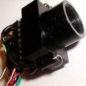
9 ========= Section 4: Camera Enclosure Note: (1) Wear safety glasses when cutting with the Dremel rotary tool. (2) Wear safety glasses when drilling = Step 1: Mark the locations for cutting 1. Mark one of the sides of the enclosure as shown in the picture bellow: = Step 2: Cut the holes for the connectors. 1. Cut out the holes, marked in step 1, using a Dremal Rotary Tool. = Step 3: Mark the locations for screw holes. 1. Place the camera board in the enclosure. 2. Align the connectors on the camera board to the holes in the enclosure 3. Mark the locations of the camera screw holes on the enclosure.
10 = Step 4: Drill the holes 1. Install a 3/32" drill bit into the drill. 2. Drill the holes, marked in step 3. ========= Section 5: Install the Camera Board in the Enclosure ============== == Step 1: Connect wire to the camera board 1. Measure and cut 14 pieces of solid 24 AWG wire, each approximately 5 inches in length. 2. Strip the end of each wire to about 1/8 inch. 3. Turn on the soldering iron and set the temparature to 700 degrees Fahrenheit. 4. Hold the stripped end of the wire against the hole in the board (where one of the pins was removed). 5. Touch the tip of the soldering iron to the wire. When the wire gets hot enough to melt the solder, push end of the wire all the way through the board (be careful not to burn your fingers when the wire gets hot). 7. Inspect the connection on the back of the board. There should be enough solder left on the board to hold the wire. However, it might require additional solder. 8. Cut off any excess wire that sticks out from the back of the board. 8. Repeat this process for the remaining wires. 9. Check the back of the board to make sure that none of the contacts are shorted together. This can be done easily with a multimeter. (Many multimeters have a continuity checker that will beep if the contacts are connected).


")
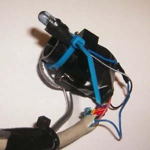
11 ==== Step 2: Connect the wire to the DB15 pin connector 1. Strip the ends of each of the wires from the camera board 2. Attach each wire to the correct pin on the DB15 pin connector, except for the ground pins (The order is important). 3. The ground pins (pins 6 and 9) should be connected to the enclosure. ====
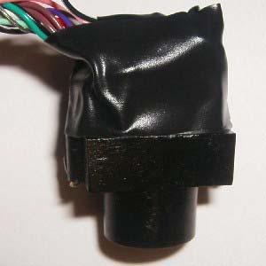
12 Step 3: Screw the camera board to the enclosure 1. Tap each of the screw holes using one of the screws. The aluminum is soft enough that the screws should tap the holes easily. However, you should work the screws back and forth to make sure that the holes are tapped well. 2. Align the camera board with the screw holes. 3. Place a nylon spacer between the camera board and the enclosure. 4. Align the spacer with one of the screw holes. 5. Insert screw, but do not tighten it down all the way. 6. Repeat steps 3-5 for remaining screws. *Note* You may need to file down one or more of the spacers to make the camera board fit correctly. ==== Step 4: Install a resistor 1. Solder a piece of wire to the top right pin on the DB15 connector (See picture from step 2). 2. Solder the other end of this wire to a 33 Ohm resistor (use 0.75W or greater resistor). 3. Connect the free end of the resistor to another piece of wire (this wire needs to be long enough to connect to a USB connector/cable). It may be useful to have an additional connector between the USB cable and the enclosure. 4. Tie the wire around one of the screws going through the camera board. 5. Run the free end of the wire out of the enclosure (can use the openning from the firewire connector). 6. Place tape around the resistor and tape it to the enclosure.


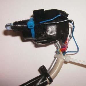
13 ==== Step 5: Put the enclosure back together
.")
14 ========= Section 6: Sensor Socket Step 1: Combine sockets 1. Combine 2 14 pin sockets together (socket on the bottom can have more than 14 pins, the picture is incorrect). This is done to prevent the pins from moving when they get hot.
15 Step 2: Strip and cut the wires. Note: These steps are done to make stripping such small pieces of wire easier. However, there may be better methods for doing this. 1. Use 22AWG solid wire, strip approximatly 3/16" insulation off of the wire spool. 2. Using the wire strippers cut through the insulation 1/4" down the wire (do not remove insulation). 3. Pull the insulation up slightly (approximatly 1/8") 4. Cut the piece of wire off the spool, leave both ends stripped. (one to 1/16" and one to 1/8") 5. Repeat steps 1-4 until there are 14 pieces of wire (try to make each piece as similar as possible). Step 3: Attach the wires Note: (1) This can be a tricky process (2) The length of each wire may need to be adjusted sligtly 1. On one side of the socket, insert one of the wires into the middle pin using the side of the wire that is stipped to 1/8". (the wire should fit very tightly in the pin, pliers may be required). 2. Hold the sensor and socket in place using the helping hands (see


16 list of tools), make sure that pin 1 of the sensor is aligned to pin 1 of the socket. 3. Carefully, solder the free end of the wire to the sensor. Do not leave the soldering iron on the sensor for more than 2 seconds at 700 degrees. 4. Insert the wire on the opposite side of the socket. It may be required to bend the prevous wire outword to make the sensor even on both sides of the socket. Also, make sure the top of the sensor is parallell with the top of the socket. 5. Solder the wire from #4 to the sensor. 6. Attach all of the remaining wires in the same fashion, make sure to check the alignment of the sensor. Also, make sure to never leave the soldering iron on the sensor for more than 2 seconds.


.")
17 ========= Section 7: Eye Camera Repeat the steps in sections 3-6 that where performed on the color camera to the black and white board level camera (make sure not to mixup the different sensors). =========
 2.")
18 = Section 8: IR filter Step 1: Cut the filter to size 1. Remove filter from package (be careful not to get many finger prints on it) 2. Cut it to 6mm square Step 2: Put super glue on lens 1. Add a small amount of supper glue around the edge of the lens


19 Step 3: Add filter to lens 1. Carefully place the filter over the lens. 2. Align the filter so that it covers the glass of the lens. 3. Make sure that the corners of the filter to not sick out. So, they are not in the way of the lens mount. =========

20 Section 9: Eye Camera Cable Step 1: Cut cable 1. Cut one of the 15pin cables to 42" in length, the sensor will not work if the cable is too long (use the side with the male connector). 2. Strip approximatly 1.5" of insulation from cable using X-acto knife 3. Peel back and remove foil sheilding Step 2: Combine two sockets and add solder 1. Push two sockets together. This will help keep the pins from moving around when they get hot. 2. Add solder to each of the pins on the bottom connector. Step 3: Add shrink wrap

21 1. Cut 12 pieces of 1/8" shrink wrap to 3/8" in length 2. Slide shrink wrap over the ends of the wires (only wires listed (in the table in step 4). Step 4: Attach wire 1. Attach the wires to the pins on the socket, skipping pins 6 and 9. Start with pins 1 and 14, these wires will need to be shortend. The wires need to get longer as they approach the other end of the socket. The wires need to be bent (see pictures below) so that the cable and socket can be easily mounted on the boom arm. The order of the wires is important Pin 1 Brown Pin 14 Purple Pin 2 Brown and White Pin 13 Gray Pin 3 Red Pin 12 White Pin 4 Red and White Pin 11 Black Pin 5 Orange Pin 10 Black and White Pin 6 Pin 9 Pin 7 Dark Green Pin 8 Light Green


22 2. Slide the shrink wrap over the pins. 3. Heat the shrink wrap with heat gun. Step 5: Attach ground wire
, so that there are two pins side by side. 2.")
 4.")
23 1. Attch a bare wire between pins 6 and Attach ground wire (the bare wire from the cable) to the wire in # 1. Step 6: LED socket 1. Cut one of the 14 pin sockets (using the x-acto knife), so that there are two pins side by side. 2. Combine the "new" two pin socket made in #1 with another socket to prevent the pins from moving when they are heated. 3. Attach a wire from one side of the two pin socket to the ground wire between pins 6 and 9 (made in step 5) 4. Attach the remaining pin from the two pin socket to the blue wire from the cable.

24 ========= Section 10: Scene Camera Cable The scene camera cable is created the same way that the eye camera cable was created. The same order should be used when connecting the wires and the ground. However, the following changes should be made: 1. No LED is required 2. The cable should not be bent at the socket.
25 ========= Section 11: Cut the Safety Glasses Step 1: Draw the pattern on the lens. Using a permanent marker, trace around the frame of the glasses onto the lens. Leave 1/8 inch of space between the line and the frame of the glasses.

26 Step 2: Remove the lens from the frame 1. Pull up on the middle of the frame (above the nose piece) while pushing down on the lens. The lens should snap free of the nose piece. 2. Pull the lens down and in front of the snap. The frame should now be behind the lens. 3. Pull the frame down about 1/2 inch from the top of the lens. 4. Remove one side of the lens from the frame by pulling one side of the frame backwards (away from the lens). Step 3: Cut the lens *Note* For this step it is recommended that a Dremal Rotary Tool is used instead of a coping saw. 1. Securely clamp the lens from the safety glasses. 2. Using a coping saw or a Dremal Rotary Tool cut alone the lines from step 2.


27 Step 4: Sand the edges Sand the edges of the lens to make sure that there are no sharp places where the user may be cut on the plastic. The surface of the lens may also be sanded so the plastic is not clear. Step 5: Replace the lens. The lens is replaced by reversing the steps that where followed when removing the lens. =========


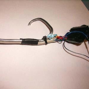
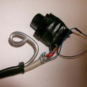
28 Section 12: Mount the Eye Camera ====
29


30 ========= Section 13: Mount the Scene Camera


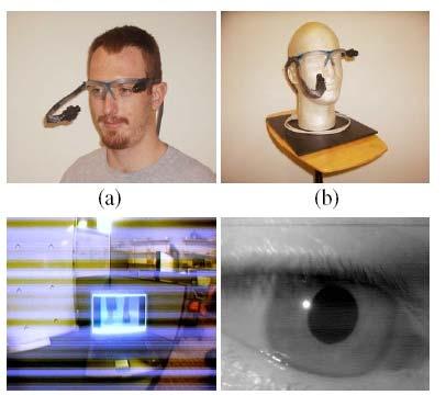
31 ========= The Completed System
32
Onwards and Upwards, Your near space guide. Figure 1. CheapBot Line Follower
 The CheapBot Line Follower is a plug-in single-board sensor for almost any programmable robot brain. With it, a robot can detect the presence of a black or white zone beneath its two sensors. In its simplest
A Backlighted LCD for your K1
 A Backlighted LCD for your K1 (K1BKLTKIT) Tom Hammond - NØSS, July 27, 2006 Rev C Thanks to Wayne Burdick, N6KR for suggesting this implementation of backlighting the K1 display. APPLICABILITY This modification
Alesis MMT8 16x Memory Expansion Modification (Black model MMT8 s) Equipment. Components required. Other bits:
 Equipment. Components required. Other bits:") Alesis MMT8 16x Memory Expansion Modification (Black model MMT8 s) by Graham Meredith, 006 Revised 15 th January 009 gmeredith1@yahoo.com.au This modification expands the memory of the Alesis MMT8 to 16x
Alesis MMT8 16x Memory Expansion Modification (Black model MMT8 s) by Graham Meredith, 006 Revised 15 th January 009 gmeredith1@yahoo.com.au This modification expands the memory of the Alesis MMT8 to 16x
How to build an Olympus D-360L Trail Camera using the PixController Universal "Digital Trail Camera Kit" w/ RS-232-U PIC Chip
 Copyright, PixController, Inc. http://www.pixcontroller.com, all rights reserved. How to build an Olympus D-360L Trail Camera using the PixController Universal "Digital Trail Camera Kit" w/ RS-232-U PIC
Figure 1. The completed programming kit List of Parts
 Many NearSys kits are programmed through a three pin header soldered to the PCB. Since a three pin receptacle is not a common termination for a serial cable, this kit contains the parts to make one. In
Parts List: Part # Tools List: Instructions:
 Parts List: Part # 1 pair of Dayton Audio B652s 300-652 1 Dayton Audio DTA-2 amplifier 300-385 1 MP3 module 320-350 1 7805 +5 VDC voltage regulator 7805 1 12 VDC 2A power supply 129-077 1 2.1 mm panel
Elecraft K3 KPA3 Power Connector Replacement Revision B, June 30, 2017 Copyright 2017, Elecraft, Inc. All Rights Reserved
 Introduction Elecraft K3 KPA3 Power Connector Replacement Revision B, June 30, 2017 Copyright 2017, Elecraft, Inc. All Rights Reserved The connectors furnishing high current to the KPA3 module have failed
Universal Keying Adapter 3+
 Universal Keying Adapter 3+ The Universal Keying Adapter Version 3+ kit will allow you to key nearly any transmitter or transceiver with a straight key, electronic keyer, computer serial or parallel port
imac Intel 27" EMC 2639 Hard Drive
 imac Intel 27" EMC 2639 Hard Drive Replacement Replace the Hard Drive in your imac Intel 27" EMC 2639. Written By: Walter Galan ifixit CC BY-NC-SA www.ifixit.com Page 1 of 26 INTRODUCTION Replacing the
4.1 Parts and Components... IV Assembly Tips... IV Assembly Precautions... IV Required Tools, Equipment and Materials..
 IV PERSONALITY MODULE ASSEMBLY 4.1 Parts and Components............ IV-1 4.2 Assembly Tips............... IV-1 4.3 Assembly Precautions............ IV-1 4.4 Required Tools, Equipment and Materials.. IV-1
edrive RAM Battery Alternate Replacement Procedure
 edrive RAM Battery Summary This technical note describes the process for replacing the TINI RAM battery with a higher capacity battery. With the edrive turned on, the external battery can be changed without
How to hardwire the Sony DSC-W35 Digital Camera
 How to hardwire the Sony DSC-W35 Digital Camera Copyright, PixController http://www.pixcontroller.com, all rights reserved. Rev. A 3/20/07 This document covers in detail how to modify the Sony DSC-W35
Alesis MMT8 16x Memory Expansion Modification (all grey model MMT8 s)
") Alesis MMT8 16x Memory Expansion Modification (all grey model MMT8 s) by Graham Meredith, 2006 Revised 13 th January 2009 gmeredith1@yahoo.com.au This modification expands the memory of the Alesis MMT8
Alesis MMT8 16x Memory Expansion Modification (all grey model MMT8 s) by Graham Meredith, 2006 Revised 13 th January 2009 gmeredith1@yahoo.com.au This modification expands the memory of the Alesis MMT8
Installing a Power over Ethernet injector
 Installing a Power over Ethernet injector AlphaEclipse StreetSmart and RoadStar signs The instructions in this document explain how to install/replace a Power over Ethernet (PoE) injector in a StreetSmart
Revised: Page 1
 Brought To You By And Designed By: Revised: 2017-05-07 Page 1 Features Of The Universal PSU Kit: Fits all standard Apple II and /// Power Supply Enclosures. (all parts included, user supplies household
When you are ready to build your computer you will have the following materials to work with.
 Copyright 2009 BOSMA Enterprises Chapter 3 Putting the Computer Together When you are ready to build your computer you will have the following materials to work with. 1. One motherboard. 2. One ribbon
Assembly of the TACOS WAT-910BD Housing v2
 1) Circuit Diagram 2) Assembly of PCB a)tools Required. Only simple hand tools are necessary to complete the assembly of the PCB. - Soldering Iron and solder - Needle nose pliers - Wire clippers/trimmers
RSL PSM-2 Power Supply Module Project: Modifying a FlatCap2
 RSL PSM-2 Power Supply Module Project: Modifying a FlatCap2 Dear Do-It-Yourselfer, The stock FlatCap2 is less than a stellar performer. Used with a CD5 CD player, for example, it gives flabby bass control,
OnePlus 5 Screen and Digitizer Assembly Replacement
 OnePlus 5 Screen and Digitizer Assembly Replacement Follow this guide to replace the screen and digitizer for the OnePlus 5. This replaces the screen as well as the frame it is attached to. Written By:
MacBook Core 2 Duo Clutch Cover
 MacBook Core 2 Duo Clutch Cover Replacement Replace the clutch cover on your MacBook Core 2 Duo. Written By: Ben Eisenman ifixit CC BY-NC-SA www.ifixit.com Page 1 of 29 INTRODUCTION Replace the curved
orban FIELD ENGINEERING BULLETIN Purpose: Units Affected: Replacement Kit, Orban Part # Replacing SSM2017 Op-Amps
 orban FIELD ENGINEERING BULLETIN March 27, 2002 Orban Models: 2200, 6200, 6200S, 8200, 8282, 9200 Purpose: Due to the elimination of the SSM2017 by its manufacturer, Orban has had to choose a replacement
Upgrade Instructions. P/N Revision A. October Printer Terminal Holder * *
 Upgrade Instructions P/N 96-08-0 Revision A October 000 480 Printer Terminal Holder P/N 96-08-0 Revision A *96080* Instructions This terminal holder connects the INTERMEC R 600 Series and 700 Series Computers
INSTALLATION INSTRUCTIONS
 2015 F-150 8 MyTouch factory display 360º Vision System (Kit # AVMS-3618) DUE TO THE COMPLEXITY OF THIS KIT PROFESSIONAL INSTALLATION IS REQUIRED CALIBRATION KIT IS REQUIRED FOR FINAL PROGRAMMING -Must
Reflowing Xbox 360 Motherboard
 Reflowing Xbox 360 Motherboard Reflow the solder on your Xbox 360's motherboard. Written By: Andrew Bookholt ifixit CC BY-NC-SA www.ifixit.com Page 1 of 31 INTRODUCTION Use this guide to reflow the solder
E1135C PDU and Pod Upgrade Procedure
 E4030-90010 Rev. B 12/2003 In this Document... Tools Needed, 2 Contents of the Upgrade Kits, 2 Installation Procedures, 4 Verifying the Power Option of the New PDU, 4 Removing the PDU from the Support
Pacific Antenna Two Tone Generator
 Pacific Antenna Two Tone Generator Description Our Two Tone Generator kit provides two non-harmonic, sine wave signals for testing audio circuits Outputs of approximately 700Hz and 1900Hz and the combination
Installing imac Intel 27" EMC 2390 Dual HDD or
 Installing imac Intel 27" EMC 2390 Dual HDD or SSD Drive Installing a secondary HDD or SSD in the mid 2010 27" imac EMC 2390. Written By: Brett Hartt ifixit CC BY-NC-SA www.ifixit.com Page 1 of 23 INTRODUCTION
Installing PRO/DGX or Pro Soloist MIDI interface. R Grieb 9/08/2017
 Installing PRO/DGX or Pro Soloist MIDI interface. R Grieb 9/08/2017 Please read these instructions before purchasing the MIDI interface, to make sure you are comfortable performing the necessary steps.
A how-to guide for replacing the DJI Phantom 4 body shell. *Replacing the body shell could also be used as a tear-down guide. Written By: GotMac
 A how-to guide for replacing the DJI Phantom 4 body shell. *Replacing the body shell could also be used as a tear-down guide. Written By: GotMac ifixit CC BY-NC-SA www.ifixit.com Page 1 of 15 INTRODUCTION
13 MMC for PC Option Modules
 Part Number M.1300.8684 MMC for PC Option Modules Manual V3.0 The information in this document is also available in the MMC for PC Hardware Manual. 13 MMC for PC Option Modules 13.1 General The MMC for
ipod Touch 5th Generation Power Button Replacement
 ipod Touch 5th Generation Power Button Replacement Remove the power/sleep button from your ipod Touch 5th Generation. Written By: Andrew Optimus Goldberg ifixit CC BY-NC-SA www.ifixit.com Page 1 of 29
PARTS LIST 1 x PC Board 36 x 5mm Red LED 36 x 12mm LED Standoff 36 x NPN Transistor 36 x 10kΩ Resistor OTHER PARTS YOU MAY NEED
 PARTS LIST 1 x PC Board 36 x 5mm Red LED 36 x 12mm LED Standoff 36 x NPN Transistor 36 x 150Ω Resistor 36 x 10kΩ Resistor 17 x Mini Toggle on-off 8 x Mini Toggle (on)-off-(on) 1 x 470Ω Resistor 1 x 47µF
BuffaloLabs WiFi Lantern Assembly guide version 1
 BuffaloLabs WiFi Lantern Assembly guide version 1 Needed equipment: Solder iron Solder wire Cutter Wire stripper (optional) Hot glue gun Overview of the components (not including USB cable and box panels)
Allen-Bradley Drives. Instructions. (For 6180 Industrial Computers)
") Instructions (For 6180 Industrial Computers) This document describes how to remove or install a Pentium processor in the 6180 Industrial Computer. Processor specifications are also provided. The processor
Instructions (For 6180 Industrial Computers) This document describes how to remove or install a Pentium processor in the 6180 Industrial Computer. Processor specifications are also provided. The processor
MacBook Core Duo Optical Drive Replacement
 MacBook Core Duo Optical Drive Replacement MacBook Core Duo optical drive replacement. Written By: irobot ifixit CC BY-NC-SA www.ifixit.com Page 1 of 18 INTRODUCTION [video: http://www.youtube.com/watch?v=8l151w_giry]
Gateway Profile 4 service guide
 Gateway Profile 4 service guide Customizing Troubleshooting Contents Replacing Components in Your Gateway Profile 4.................. 1 About this guide.....................................................
Contents. BMS icom Manual
 Contents 1. Introduction... 2 2. Safety Overview... 2 3. Package Contents... 3 4. Required Tools... 4 5. Installation Instructions... 6 Step 1: Mount BMS Unit... 6 Step 2: Clamp Setup... 6 Step 3: Sensing
Mailbox Notification Service. Created by Adam Kohring
 Mailbox Notification Service Created by Adam Kohring Last updated on 2015-06-24 10:20:07 PM EDT Guide Contents Guide Contents Overview Parts List Adafruit Products Additional Products Print the Circuit
Assembling the Printed Circuit Board for the EDE1200 Robot
 This board receives instructions from either a CBL2, a LabPro or (with an adapter cable) an original CBL. The board has two 595 shift registers (each providing 8 bits of on-board memory) and two EDE1200
ipod Touch 4th Generation 30 Pin Dock Connector Replacement
 ipod Touch 4th Generation 30 Pin Dock Connector Replacement Learn how to replace the 30 pin dock connector on an ipod touch 4th generation. Written By: Gabe Keehn ifixit CC BY-NC-SA www.ifixit.com Page
Figure 1. The BalloonSat Mini v4.0 Programmable Flight Computer. Parts List
 The heart of the NearSys Mini v4.0 flight computer is the PICAXE-08M2. The PICAXE is a microcontroller and that makes the BalloonSat Flight Computer programmable. The PICAXE-08M2 s internal memory is limited
ASUS Zen Pad 10 Micro USB Port & Camera Replacement
 ASUS Zen Pad 10 Micro USB Port & Camera Replacement Remove the motherboard and replace the camera and micro USB port. Written By: Mr Circuit ifixit CC BY-NC-SA www.ifixit.com Page 1 of 13 INTRODUCTION
To connect the AC adapter:
 Replacing the AC Adapter Replacing the AC Adapter 3 Plug the power cord into a wall outlet. The power indicator turns on. To connect the AC adapter: Connect the power cord to the AC adapter. Power indicator
Upgrading LVDS Cables Instruction Sheet
 Upgrading LVDS Cables Instruction Sheet INTRODUCTION Use the following instructions to replace the LVDS cables in CP2000-M/MR projectors. The new cables are slightly longer in length and allow for better
Seeburg JCU-DEC Kit Convert Your Seeburg DEC Wallbox Into a Jukebox
 Seeburg JCU-DEC Kit Convert Your Seeburg DEC Wallbox Into a Jukebox MP3 Compact Flash Player Coin Operated or Free Play Integrated Power Amplifier Line-Out to External Amplifier Programmable Autoplay IR
OpenSprinkler v2.2u Build Instructions
 OpenSprinkler v2.2u Build Instructions (Note: all images below are 'clickable', in order for you to see the full-resolution details. ) Part 0: Parts Check Part 1: Soldering Part 2: Testing Part 3: Enclosure
Casio CZ. Non volatile memory modification Installation instructions version copyright 2013 Artefacts
 Casio CZ Non volatile memory modification Installation instructions version 2.0 2017 www.artefacts.nl copyright 2013 Artefacts Introduction The Casio CZ-101 and CZ-1000 do not have a separate backup battery
Canon EOS Rebel T2i Top Cover Replacement
 Canon EOS Rebel T2i Top Cover Replacement Replacing the top piece of a Canon T2i (550D). In my case, I had a broken hot-shoe, but as most controls on this camera are built into the same part, this repair
MacBook Core 2 Duo Display Replacement
 MacBook Core 2 Duo Display Replacement Written By: irobot ifixit CC BY-NC-SA www.ifixit.com Page 1 of 23 INTRODUCTION Change out the entire display assembly, including the inverter, Airport antennas, hinges
Phi-panel backpack assembly and keypad options Dr. John Liu 12/16/2012
 Phi-panel backpack assembly and keypad options Dr. John Liu 12/16/2012 1. Introduction:... 3 Currently available:... 3 2. Backpack assembly... 4 3. Connecting to a keypad... 6 4. Rotary encoder keypads...
Upgrading and Servicing Guide
 Upgrading and Servicing Guide Copyright Information The only warranties for Hewlett-Packard products and services are set forth in the express statements accompanying such products and services. Nothing
Figure 1. The Programmable Flight Computer.
 The BalloonSat Flight Computer There are 22 parts in this BalloonSat flight computer, the heart of which is the PICAXE- 08M2. The PICAXE is a microcontroller; making the BalloonSat Flight Computer programmable.
Assembly Instructions IV-11 DCF, melody
 This IV-11 clock is the next generation to the IV-11 Quartz, DCF, melody. This is not a beginner kit. It requires soldering experience on the IV-18 and the IV-3A board The switching power supply wall adapter
Mac Mini Model A1176 SSD Dual Drive
 Mac Mini Model A1176 SSD Dual Drive Installation Trade your optical drive for a second hard drive. Written By: Dozuki System 2017 guides.crucial.com Page 1 of 16 INTRODUCTION Use this guide to trade your
Upgrading and Servicing Guide
 Upgrading and Servicing Guide The only warranties for Hewlett-Packard products and services are set forth in the express statements accompanying such products and services. Nothing herein should be construed
Assembly Guide. LEDs. With these assembly instructions, you can easily build your own SWT16. All required components are included in this kit.
 Assembly Guide With these assembly instructions, you can easily build your own SWT16. All required components are included in this kit. You need the following tools: soldering iron, wire cutter and solder.
OpenSprinkler v2.1u Build Instructions
 OpenSprinkler v2.1u Build Instructions (Note: all images below are 'clickable', in order for you to see the full-resolution details. ) Part 0: Parts Check Part 1: Soldering Part 2: Testing Part 3: Enclosure
Installing MacBook Pro 15" Unibody Mid 2009 Dual Hard Drive
 Installing MacBook Pro 15" Unibody Mid 2009 Dual Hard Drive Use this guide to install a second hard drive in place of the optical drive. Written By: Brittany McCrigler ifixit CC BY-NC-SA www.ifixit.com
The Radio Control Temperature Logger (RCTL) Manual For hardware version 1.0 Manual version 1.0b
 Manual For hardware version 1.0 Manual version 1.0b") The Radio Control Temperature Logger (RCTL) Manual For hardware version 1.0 Manual version 1.0b All materials owned by Dan Gebhardt Introduction This device records the temperature of a model engine during
The Radio Control Temperature Logger (RCTL) Manual For hardware version 1.0 Manual version 1.0b All materials owned by Dan Gebhardt Introduction This device records the temperature of a model engine during
imac Intel 27" Retina 5K Display Fan
 imac Intel 27" Retina 5K Display Fan Replacement Replace a broken or noisy fan in your imac Intel 27" Retina 5K Display. Escrito por: Sam Lionheart ifixit CC BY-NC-SA es.ifixit.com Página 1 de 18 INTRODUCCIÓN
imac Intel 27" Retina 5K Display CPU Replacement
 imac Intel 27" Retina 5K Display CPU Replacement Replace or upgrade the CPU in your imac Intel 27" Retina 5K Display. Written By: Sam Lionheart ifixit CC BY-NC-SA www.ifixit.com Page 1 of 36 INTRODUCTION
Morse Code Practice Oscillator
 Features Description Keyer speed range: Limited only by keying source True Sine wave tone output Tone Volume Control Tone Frequency Control Internal Speaker 1/8 External Speaker/Headphone Jack RCA Key
3M Add-On Terminals 4220P (100, 200, 300 & 400 pairs)
") 3M Add-On Terminals 4220P (100, 200, 300 & 400 pairs) Instructions August 2011 3 78-8130-2330-1-C 1.0 General 1.1 The 3M Add-On Terminals 4220P-100, 4220P-200, 4220P-300 and 4220P-400 are designed to expand
3M Add-On Terminals 4220P (100, 200, 300 & 400 pairs) Instructions August 2011 3 78-8130-2330-1-C 1.0 General 1.1 The 3M Add-On Terminals 4220P-100, 4220P-200, 4220P-300 and 4220P-400 are designed to expand
imac Intel 27" EMC 2546 SSD Replacement
 imac Intel 27" EMC 2546 SSD Replacement Remove your imac's SSD, or the SSD portion of your imac's Fusion Drive. Written By: Dozuki System 2017 guides.crucial.com Page 1 of 33 INTRODUCTION If your imac
SharpSky Focuser Construction. SharpSky Focuser. Construction Document V st December 2012 Dave Trewren 1
 SharpSky Focuser Construction Document V0.12 1st December 2012 Dave Trewren 1 Contents 1 General... 3 1.1 Change Record... 3 1.2 References... 3 2 Introduction... 5 3 SharpSky driver installation... 5
CINTENNA ANTENNA REPAIR GUIDE
 The Cintenna is a great tool when looking to transmit WIRELESS DMX data over obstacles or hard to reach places. Wireless DMX can have its issues when not having a good line of sight between the transmitter
ipad Mini Wi-Fi Front Facing Camera Replacement
 ipad Mini Wi-Fi Front Facing Camera Replacement Replace the Front Facing Camera in your ipad Mini Wi-Fi. Written By: Andrew Optimus Goldberg ifixit CC BY-NC-SA www.ifixit.com Page 1 of 42 INTRODUCTION
The DIG-CXXXX Installation and User s Manual
 The DIG-CXXXX Installation and User s Manual Table of Contents Last Updated: August 23, 2002 READ THIS FIRST!!!... 1 Introduction to the Installation Process:... 2 Connecting to the Player Circuit Board...
July Manual 10-slide disk outdoor viewer
 Ing. J. de Wijs. Populierstraat 44, 4131 AR Vianen, the Netherlands Tel/Fax. +31 (0)347-372242 e-mail: info@dewijs-3d.com Website: www.dewijs-3d.com Design and production of stereoscopic instruments. July
imac Intel 27" Retina 5K Display Fan
 imac Intel 27" Retina 5K Display Fan Replacement Written By: Dozuki System 2017 guides.crucial.com Page 1 of 17 INTRODUCTION Use this guide to replace a broken or noisy fan in your imac Intel 27" Retina
MacBook Core 2 Duo Optical Drive
 MacBook Core 2 Duo Optical Drive Replacement Written By: Dozuki System 2017 guides.crucial.com Page 1 of 17 INTRODUCTION Upgrade or replace the combo or SuperDrive (requires a slim drive). TOOLS: Coin
Q2 XBee Handheld Controller Assembly Guide
 Q2 XBee Handheld Controller Assembly Guide Copyright Quantum Robotics Inc. Q2 Controller V1.0 1 Parts List: The kit comes with 14 individual bags. 1. Case Top and Bottom 2. Case Screw Package containing:
imac Intel 27" EMC 2546 Right Speaker
 imac Intel 27" EMC 2546 Right Speaker Replacement Replace your imac's right speaker. Written By: Andrew Optimus Goldberg ifixit CC BY-NC-SA www.ifixit.com Page 1 of 18 INTRODUCTION Missing half your beats?
PowerBook G4 Aluminum 12" GHz Display Data Cable Replacement
 PowerBook G4 Aluminum 12" 1-1.5 GHz Display Data Cable Replacement Written By: Matthew Newsom ifixit CC BY-NC-SA www.ifixit.com Page 1 of 47 INTRODUCTION Replace a damaged display data cable to restore
imac Intel 27" Retina 5K Display SATA Cable
 imac Intel 27" Retina 5K Display SATA Cable Replacement Written By: Dozuki System 2017 guides.crucial.com Page 1 of 32 INTRODUCTION Use this guide to replace the SATA cable on the back of the logic board
Mini B lue M idnight
 Mini Blue Midnight 2011 by Shattered Glass Audio. All rights reserved. No part of this document may be reproduced or transmitted in any form or by any means, electronic, mechanical, photocopying, recording,
FUSION MS-RA70/MS-RA70N Installation Instructions
 FUSION MS-RA70/MS-RA70N Installation Instructions Important Safety Information WARNING Failure to follow these warnings and cautions could result in personal injury, damage to the vessel, or poor product
GM NBS Truck CCD Backup Camera Kit Installation Guide
 CS GM1 GM NBS Truck 2007 2012 CCD Backup Camera Kit Installation Guide Thank you for your purchase! These instructions are intended for the do it yourselfer who decides to install the camera without professional
B&W RearView Camera Installation & Operation
 B&W RearView Camera Installation & Operation CA52 (Camera) FOR MORE INFORMATION WWW.STRATEGICVISTA.COM BEFORE OPERATING THIS SYSTEM, PLEASE READ THIS MANUAL THOROUGHLY AND RETAIN IT FOR FUTURE REFERENCE
Mac Mini Mid 2010 SSD Installation
 Mac Mini Mid 2010 SSD Installation Replace your Mac Mini Mid 2010's hard drive for more storage space and an increase in speed. Written By: Dozuki System 2017 guides.crucial.com Page 1 of 15 INTRODUCTION
Installation Instruction VCPRGBGM05 - rev1.5 RGB Interface Harness modification Navigation Radio
 Introduction The following instruction procedure is for the RGB interface to a GM 05 Nav Radio as part of the Webasto Product NAVCam Back-up Camera (VCP-0000220). In addition, an installer will need to
Mikrokopter FPV Camera Mount. Assembly Manual
 Assembly Manual Introduction Thank you for purchasing the. The FPV Camera Mount is provided as a kit and requires assembly. The assembly of the mount can take up to 15-20 minutes for an inexperienced builder.
Replacement Keyswitch Assembly
 Installation Instructions Replacement Keyswitch Assembly (Catalog No. 2711E-NKSW1) Applicable Terminals Use this replacement keyswitch with PanelView Terminals 2711-KA1, -KC1, -TA1, -TC1, -TA4, -TC4 and
DirectCommand Installation RoGator Model Year Ag Leader Technology
 Note: Indented items indicate parts included in an assembly listed above Part Name/Description Part Number Quantity Direct Command Kit 4100801 1 Dual Lock 2000052-9 1 Dual Lock 2000053-9 1 Quick Reference
PowerBook G4 Aluminum 12" GHz Logic Board Replacement
 PowerBook G4 Aluminum 12" 1-1.5 GHz Logic Board Replacement Written By: irobot ifixit CC BY-NC-SA www.ifixit.com Page 1 of 32 INTRODUCTION This motherboard includes all ports except the DC-In board. TOOLS:
PowerBook G4 Aluminum 12" GHz Left Clutch Hinge Replacement
 PowerBook G4 Aluminum 12" 1-1.5 GHz Left Clutch Hinge Replacement Written By: Matthew Newsom ifixit CC BY-NC-SA www.ifixit.com Page 1 of 50 INTRODUCTION Replace a broken clutch hinge to make your display
Written By: Sam Lionheart
 iphone 6 Front Panel Replacement Replace the bare front panel of an iphone 6. Written By: Sam Lionheart ifixit CC BY-NC-SA www.ifixit.com Page 1 of 27 INTRODUCTION For an easier repair, use our fix kit
Installation Manual. Table of Contents
 Table of Contents Table of Contents... 4-1 4.1 Confirming the Installation Preparations... 4-1 4.2 Installation Flowchart... 4-1 4.3 Mounting the Switch to the Designated Position... 4-2 4.3.1 Mounting
imac Intel 21.5" EMC 2389 Stand Replacement
 imac Intel 21.5" EMC 2389 Stand Replacement Replace a broken or cosmetically unappealing stand on the imac 2389 21.5 Written By: Aaron Cooke ifixit CC BY-NC-SA www.ifixit.com Page 1 of 30 INTRODUCTION
LANCER / LANCER EVOLUTION (2008 ) REAR VIEW CAMERA MZ380462EX INSTALLATION AND HANDLING INSTRUCTIONS
 REAR VIEW CAMERA MZ380462EX INSTALLATION AND HANDLING INSTRUCTIONS") LANCER / LANCER EVOLUTION (2008 ) REAR VIEW CAMERA MZ380462EX INSTALLATION AND HANDLING INSTRUCTIONS Navigation (MMCS) unit Camera Thank you for purchasing the Mitsubishi Genuine Accessory. To install
LANCER / LANCER EVOLUTION (2008 ) REAR VIEW CAMERA MZ380462EX INSTALLATION AND HANDLING INSTRUCTIONS Navigation (MMCS) unit Camera Thank you for purchasing the Mitsubishi Genuine Accessory. To install
Written By: Sam Lionheart
 iphone 5s Earpiece Speaker Replacement Replace the earpiece speaker in an iphone 5s. Written By: Sam Lionheart ifixit CC BY-NC-SA www.ifixit.com Page 1 of 22 INTRODUCTION Use this guide to replace a broken
Figure 1. The BalloonSat Mini Servo v1.0 Programmable Flight Computer with servo. Parts List
 The heart of the NearSys Mini Servo v1.0 flight computer is its PICAXE-08M2, a microcontroller, which makes the flight computer smart. The PICAXE-08M2 s internal memory is limited to 2048 bytes, or about
User s Guide TURBO Pinewood Derby Finish Line and Timer Release /31/2011 NewBold Products, Atlanta GA
 User s Guide TURBO Pinewood Derby Finish Line and Timer Release 2.1 12/31/2011 NewBold Products, Atlanta GA www.newboldproducts.com 2 1. YOUR SHIPMENT Thank you for purchasing the TURBO, Pinewood Derby
P160 User s Manual Manuel de l utilisateur Anwenderhandbuch Manuale per l operatore Manual del usuario
 P10 User s Manual Manuel de l utilisateur Anwenderhandbuch Manuale per l operatore Manual del usuario At Antec, we continually refine and improve our products to ensure the highest quality. So it's possible
Huawei Ascend P6-U06 Screen/LCD Display Replacement
 Huawei Ascend P6-U06 Screen/LCD Display Replacement Replace the Huawei Ascend P6-U06's screen and LCD display. Written By: Zachary Rose ifixit CC BY-NC-SA www.ifixit.com Page 1 of 17 INTRODUCTION Replace
itech Training Courses iphone 5S LCD Assembly Replacement Guide
 itech Training Courses iphone 5S LCD Assembly Replacement Guide 2014 icracked, Inc. All rights reserved. ios, all Apple product names, and Apple logos are trademark property of Apple, Inc. The content
Tubbutec Sumtiple Kit Version Construction Manual
 Tubbutec Sumtiple Kit Version Construction Manual This document describes the construction of the Sumtiple Kit. The following parts are included: 1x Sumtiple PCB with SMD-Parts already soldered 1x Front
How to Assemble a Desktop PC
 How to Assemble a Desktop PC By Taylor Koch iii Table of Contents Introduction to Building a Desktop PC... 1 Preparation and Precautions... 3 PC Parts... 3 Basic Tools... 3 Safety Precautions... 3 Installing
Bullet Camera Installation in an Outdoor Enclosure
 Bullet Camera Installation in an Outdoor Enclosure This document explains how to install a Bullet Camera into an outdoor enclosure. Step 1: Install the Wi-Fi Antenna (Optional) If you will be installing
ipod Classic Headphone Jack & Hold Switch Replacement
 ipod Classic Headphone Jack & Hold Switch Replacement Replace Headphone Jack & Hold Switch to fix no audio and/or no unlock Written By: irobot ifixit CC BY-NC-SA www.ifixit.com Page 1 of 22 INTRODUCTION