Bitty Rover. Recommended Age: 12 and up Difficulty Level: 3/5 (Soldering Required, programming, connecting wires, small parts choking hazard)
|
|
|
- Lewis Robinson
- 5 years ago
- Views:
Transcription

 www.rabbitrobots.")
1 Bitty Rover Bitty Rover V2.3 Assembly Instructions Recommended Age: 12 and up Difficulty Level: 3/5 (Soldering Required, programming, connecting wires, small parts choking hazard) WARNING: CHOKING HAZARD This kit contains small parts. Not suitable for children under 3 years
2 ID QTY Description Re-Order # A 1 Bitty Rover Level 1 BR-001 B 1 Bitty Rover Level 2 BR-002 C 1 Bitty Rover Level 3 BR-003 D 1 Bitty Rover Level 4 BR-004 E 2 Bitty Rover Motor Mount BR-005 F 1 Bitty Rover Front Bumper BR-006 G 1 Bitty Rover Back Bumper BR-007 H 1 Bitty Rover Pen Mount BR-008 I 1 Ultrasonic Sensor Mount 35mm USM J 1 LCD Mount 45mm LCD K 1 Servo Mount 45mm SM L 1 Antenna Mast 45mm AM-45-F M 1 Antenna Mount AM-01 N 1 Roller Bearing 5/8", Menards #9110 M9110 O 9 M2 Wood Screw - 6mm M2X6 P 15 M3 Screw Nylon Black N-M3X5 Q 5 M3 Nylon Washer - 3X9mm NW-3X9 R 4 M3 Screw - 25mm M3X25 R2 4 M3 Screw - 15mm M3X15 S 10 M3 Nylon Standoff - 5mm NSO-3X5 T 8 M3 Nylon Lock Nuts NLN-M3 U 24 M4 Screw 8mm M4X8 U2 12 M4 Flange Screw 8mm M4FX8 V 4 M4 Nylon Standoff - 35mm NSO-4X35 W 8 M4 Nylon Standoff - 45mm NSO-4X45 X 2 Gearbox / Motor Assembly TTGearbox48 Y 2 Wheel and Tire for TT Motor TTWheel-Y Z 5 Line Sensor Module (4-pins) TCRT-5000 AA 1 9G RC Servo SERVO-9G BB 1 Ultrasonic Sensor HC-SR04 CC 1 LCD Display 1602 I2C LCD-I2C DD 1 L298 Motor Driver Board L298N EE 1 Arduino Mega 2560 A-MEGA2560 FF 1 USB Cable - 30cm - A/B CBL-USB GG 1 3 Position 2 Pole Power Switch SW-3P2P HH 1 8xAA Battery 1.5V Holder BH-08AA II 1 2.1mm Power Connector - Male Conn21M JJ 1 2.1mm Power Connector - Female Conn21F KK 1 2.1mm Power Connector - Male w/ 10" cable Conn21CBL LL 10 Module Jumper Wires MF - 20cm JumpMF-20 LL2 10 Module Jumper Wires MF - 20cm JumpFF-20 MM 1 Motor Power Wires M-Wire OO 1 Sound Buzzer KPIEZO-001 PP 1 Voltage Regulator L2596DC QQ 1 Light Sensor CS-001 RR 1 Serial - WIFI Wireless Transceiver ESP-8266 SS 2 Micro Cherry Switch CHSW-001 TT 1 Arduino Sensor Shield Keyes-V5 SSHLD-V5 UU 1 Resistor assortment (12 resistors, 1 diode) RDPack-01
3 Required Tools: Phillips #1 Screwdriver Phillips #2 Screwdriver Provided plastic M3 Wrench Extra Recommended Tools: Sandpaper Needle File Knife Wire cutters This kit is intended to be the base platform for your education into robotics. Please take the opportunity to expand your robot to do many more functions. Additions you can do: Add a 9G servo between Level 2 and Level 3 for controlling an ink Pen or Marker to go UP and Down. Add a 9G servo between Level 2 and Level 3 for waving a flag? Add a standard servo or 9G servo at Level 4... for whatever you want. Use the extra mount areas for the HC-04 BlueTooth, ESP 8266 Wifi, Accelerometers, Gyroscopes,..etc. Mount opto-interrupter to track the motor encoders. Projects: Play musical beeps Random dance movement with beeps Display the motor command speed while moving Display the Ultrasonic distance on the display Detect the wall to avoid hitting it Wave a flag as you drive around Use the robot to draw Spirograph art Connect to a network and host a web site Control the robot from a PC web site Control the robot from a PC application (using UDP network communications) Control the robot from your tablet or cell phone


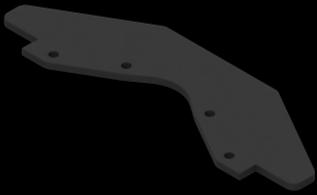
4 1) Mount the Castor Bearing to the Level 1 Level 1 Roller Bearing Bottom View Top View


")


5 2) Mount the Back Bumper to the Level 1 Back Bumper 3) Mount the Front Bumper to Level 1 Front Bumper
 Mount the M3 Standoffs for L298N motor driver board M3-5mm Standoffs")
6 4) Mount the M4x35mm Standoffs for Level 1 M4-35mm Standoffs Bottom View Top View 5) Mount the M3 Standoffs for L298N motor driver board M3-5mm Standoffs


")

7 6) Mount the L298N motor driver board to the standoffs L298N M3x9mm Screws 7) Modify the TCRT5000 sensors Bend the leads straight


 Mount")

8 Remove the extra parts off the head of the sensor Re-solder the head of the sensor to be as close to the circuit board as possible Be sure to cut the extra wire 8) Mount the TCRT5000 sensors Modified IR Reflective Sensors M3x9mm Screws


9 9) Mount the Ultrasonic sensor Ultrasonic Mount M2x6mm Screws Ultrasonic Sensor 10) Mount the LEFT motor gearbox to the plate Motor Mount M3x25mm Screws M3 Nuts Motor
10 11) Mount the RIGHT motor gearbox to the plate Motor Mount M3x25mm Screws M3 Nuts Motor 12) Mount the wheels Wheels


11 13) Put the motor plates and ultrasonic plate onto the Level 1 14) Mount the Standoffs to Level 2 Level 2 M4-35mm Standoffs
12 15) Mount the Level 2 to the standoffs of Level 1 16) Mount the M3 Standoffs for the Mega 2560 M3-5mm Standoffs
 Mount the Mega 2560 Arduino Mega 2560 M3x9mm")
13 17) Mount the main power switch Switch M2x6mm Screws 18) Mount the Mega 2560 Arduino Mega 2560 M3x9mm Screws

 Mount")


14 19) Mount the Upper Pen Mount Pen Mount 20) Mount the Standoffs to Level 3 Level 3 Top View M4-35mm Standoffs Bottom View


15 21) Put the servo mount on Level 2 and mount Level 3 to the Standoffs Servo Mount 22) Mount the voltage regulator Voltage Regulator M2x6mm Screws


16 23) Mount the LCD Display to the plate LCD Mount LCD M2x6mm Screws 24) Put the LCD Display Mount onto Level 3


")


17 25) Mount the Level 4 to the Standoffs of Level 3 Level 4 26) Assemble the Antenna Mast Antenna Mast M2x6mm Screw Antenna Mount
18 27) Press the Antenna mast into the receiver slots DONE.
Number Name Description Notes Image 0101 Resistor, 100 ohm. brown-black-browngold. ¼ watt, 5% tolerance, red-red-brown-gold. brown-black-red-gold.
 Passive Components 0101 Resistor, 100 brown-black-browngold. 690620 0102 Resistor, 220 red-red-brown-gold. 690700 0103 Resistor, 1000 brown-black-red-gold. 690865 0104 Resistor, 10k 0201 Capacitor, 1 µf,
Arduino Robots Robot Kit Parts List
 Arduino Robots Robot Kit Parts List (1) Metal Chassis (2) Push Button Activators (2) Servo Motors w/ Cross Wheels (2) IR Receivers (1) Control Board (1) Piezo Speaker (1) Dual-Sided Screwdriver (1) Cotter
Web Site: Forums: forums.parallax.com Sales: Technical:
 Web Site: www.parallax.com Forums: forums.parallax.com Sales: sales@parallax.com Technical: support@parallax.com Office: (916) 624-8333 Fax: (916) 624-8003 Sales: (888) 512-1024 Tech Support: (888) 997-8267
FOOTBALLER ROBOT KIT C-9893
 FOOTBALLER ROBOT KIT C-9893 NOTE: This kit is recommended for children aged 14 years, always accompanied by an adult www.cebekit.com - info@cebekit.com Contents Multi-Channel I/R Remote Control Box: 1.
Quick Guide WARNING: CHOKING HAZARD - Small parts. Not for children under 3 years old. mbot is an educational robot kit for beginners to get hands-on
 MAKER WORKS TECHNOLOGY INC Technical support: support@makeblock.cc www.makeblock.cc Great tool for beginners to learn graphical programming, electronics and robotics. :@Makeblock : @Makeblock : +Makeblock
Rover 5. Explorer kit
 Rover 5 Explorer kit The explorer kit provides the perfect interface between your Rover 5 chassis and your micro-controller with all the hardware you need so you can start programming right away. PCB Features:
ROBOT LINE TRACKING MOUSE KIT C-9801
 ROBOT LINE TRACKING MOUSE KIT TOOLS you'll need Alimentation 4 batteries 1,5 V AA (not included) The mouse is a line follower robot that follows a black line (or any other color) on a white background
Parts List Pictures for reference only
 Ultimate Robot Kit MAKER WORKS TECHNOLOGY INC No. 426, F/4, Gonglehuating Business Building, Xinhu Road, Xixiang Sub-district, Bao an District, Shenzhen, 518102 China. Please contact with us if you need
Insert the male, 90 angled, 2x10 connectors into the corresponding 2x10 sockets and put them in place, flat under the PCB. Solder.
 MC624 Assembly guide Safety warning The kits are main powered and use potentially lethal voltages. Under no circumstance should someone undertake the realisation of a kit unless he has full knowledge about
Arduino Smart Robot Car Kit User Guide
 User Guide V1.0 04.2017 UCTRONIC Table of Contents 1. Introduction...3 2. Assembly...4 2.1 Arduino Uno R3...4 2.2 HC-SR04 Ultrasonic Sensor Module with Bracket / Holder...5 2.3 L293D Motor Drive Expansion
Page 1 / 14. Dear Makerspace User,
 Dear Makerspace User, This list will give you an overview of all the parts that can be bought at the Student Project House Makerspace Electronics Shop. To easily find the correct part we sorted them in
How-To #3: Make and Use a Motor Controller Shield
 How-To #3: Make and Use a Motor Controller Shield The Arduino single-board computer can be used to control servos and motors. But sometimes more current is required than the Arduino can provide, either
Installation/assembly manual for DCC/Power shield
 Installation/assembly manual for DCC/Power shield The DCC circuit consists of the following components: R1/R6 R2/R3 R4/R5 D1 C2 2 kω resistor ½ Watt (colour code Red/Black/Black/Brown/Brown) 10 kω resistor
CP5176 Assembly guide. Soldering. CP5176 Assembly guide Main PCB PCB split. Document revision 2.1 Last modification : 12/11/17
 CP5176 Assembly guide Safety warning The kits are main powered and use potentially lethal voltages. Under no circumstance should someone undertake the realisation of a kit unless he has full knowledge
Mikrokopter FPV Camera Mount. Assembly Manual
 Assembly Manual Introduction Thank you for purchasing the. The FPV Camera Mount is provided as a kit and requires assembly. The assembly of the mount can take up to 15-20 minutes for an inexperienced builder.
Attaching DX Encoders to your Majestic Carriage
 Attaching DX Encoders to your Majestic Carriage Encoders are the white wheels that you need to have on your carriage in order for the stitch regulation to work. Encoders detect the movement of the machine
A B C D REV 1 SHEET 1 OF 1 1 G NO assy_011 DW TITLE SIZE C SCALE 9/17/2016 N 2 2 FG APPROVED CHECKED QA M Henri DRAW PHALANX A B C D
 4 A BPHALANX Greetings and good fortune be on you as you have aquired your new greatness. As you work through the assembly passages, please, READ THE DIRECTIONS! There are fine points covered that you
LEGO BB-8 Release: LEGO BB-8. Learn how to automate a LEGO BB-8for motion, light, and sound using Crazy Circuits. Written By: Joshua
 LEGO BB-8 Learn how to automate a LEGO BB-8for motion, light, and sound using Crazy Circuits. Written By: Joshua 2018 browndoggadgets.dozuki.com/ Page 1 of 18 INTRODUCTION We absolutely LOVE the new LEGO
TA0139 USER MANUAL ARDUINO 2 WHEEL DRIVE WIRELESS BLUETOOTH ROBOT KIT
 TA0139 USER MANUAL ARDUINO 2 WHEEL DRIVE WIRELESS BLUETOOTH ROBOT KIT I Contents Overview TA0139... 1 Getting started: Arduino 2 Wheel Drive Wireless Bluetooth Robot Kit using Arduino UNO... 1 2.1. What
THE COMPLETE ALL IN ONE ROBOT 360 NANO BOT
 THE COMPLETE ALL IN ONE ROBOT 360 NANO BOT LINE FOLLOWER FIVE LINE SENSORS FOR SCANNING WHITE OR BLACK LINE OBSTACLE AVOIDER TWO OBSTACLE SENSORS CAN DETECT OBSTACLES AND MEASURE DISTANCE BLUETOOTH CONTROL
Post Tenebras Lab. Written By: Post Tenebras Lab
 Post Tenebras Lab PTL-ino is an Arduino comptaible board, made entirely out of through-hole components. It is a perfect project to learn how to solder and start getting into the world of micro controllers.
AlphaBot2 robot building kit for Arduino
 AlphaBot2 robot building kit for Arduino SKU 110060864 Description This AlphaBot2 robot kit is designed to use with an Arduino compatible board UNO PLUS. It features rich common robot functions including
PARTS LIST 1 x PC Board 36 x 5mm Red LED 36 x 12mm LED Standoff 36 x NPN Transistor 36 x 10kΩ Resistor OTHER PARTS YOU MAY NEED
 PARTS LIST 1 x PC Board 36 x 5mm Red LED 36 x 12mm LED Standoff 36 x NPN Transistor 36 x 150Ω Resistor 36 x 10kΩ Resistor 17 x Mini Toggle on-off 8 x Mini Toggle (on)-off-(on) 1 x 470Ω Resistor 1 x 47µF
Desktop housing AZ/EL Kit V1.2 for ERC-M Instructions. Instructions
 Instructions Desktop housing AZ/EL it V1.2 for ERC-M Instructions Congratulations for buying your Desktop housing AZ/EL for ERC-M. This document will guide you through the needed steps for assembly of
HUB-ee BMD-S Arduino Proto Shield V1.0
 HUB-ee BMD-S Arduino Proto Shield V1.0 User guide and assembly instructions Document Version 1.0 Introduction 2 Schematic 3 Quick user guide 4 Assembly 5 1) DIP Switches 5 2) Micro-MaTch Connector Headers
acknowledgments...xiii foreword...xiv
 Contents in Detail acknowledgments...xiii foreword...xiv Introduction... xv Why Build and Learn About Robots?...xvi Why the Raspberry Pi?... xvii What Is in This Book?... xvii Who is This Book For?...xix
Last Updated May 11, Electronics and Robotics LLC. ootbrobotics.com
 µpad Proto Base Assembly Guide Last Updated May 11, 2015 Table of Contents Required Tools... 5 Recommended Tools... 5 Assembly Procedure... 6 Step 1: Break Pin Headers to Size... 6 Table 1: Header Cut
Wii Nunchuk Transceiver. Wiring Diagrams
 Wii Nunchuk Transceiver Wiring Diagrams Wii Nunchuk Controller Wiring SCL SCL SDA +3v3 +3v3 Det SDA To Nunchuk Controller Top View Bottom View Bottom View 2.4GHz Wireless Transceiver CMD RXD TXD VCC 220Ω
Installation Guide. Retrofit Kit for USB Ready Intraoral Systems
 Installation Guide Retrofit Kit for USB Ready Intraoral Systems Table of Contents Wall-Mount Retrofit Kit... 2 Introduction... 2 Connecting the Articulating and Horizontal Arm Cables... 2 Installing the
1. Introduction Packing list Parts Introduction Uno R3 Board for Arduino Specifications... 6
 Table of Contents Smart Bluetooth Robot Car Kit for Arduino 1. Introduction...4 1.1 Packing list...5 2. Parts Introduction...6 2.1 Uno R3 Board for Arduino...6 2.1.1 Specifications... 6 2.2 HC-SR04 Ultrasonic
Sten-SLATE ESP. Introduction and Assembly
 Sten-SLATE ESP Introduction and Assembly Stensat Group LLC, Copyright 2016 Legal Stuff Stensat Group LLC assumes no responsibility and/or liability for the use of the kit and documentation. There is a
SRI-02 Speech Recognition Interface
 SRI-02 Speech Recognition Interface Data & Construction Booklet The Speech Recognition Interface SRI-02 allows one to use the SR-07 Speech Recognition Circuit to create speech controlled electrical devices.
CONSOLE CONNECTOR KIT 9501 INSTALLATION INSTRUCTIONS
 CONSOLE CONNECTOR KIT 9501 INSTALLATION INSTRUCTIONS FOR USE WITH: HAMMOND Organ Models L-100, M-100 Series, M-l, M-2, M-3 LESLIE Speaker Models 760, 770, 825 KIT CONTENT Console Connector Assembly 043075
RC Tractor Guy Controller V2.1 Assembly Guide
 RC Tractor Guy Controller V. Assembly Guide Features 0 Push button inputs Dual axis thumb sticks with built-in push button Rotary encoders with built-in push button MCU Socket to suit Meduino Mega 560
Bill of Materials: Picaxe-based IR Control Module Pair PART NO
 Picaxe-based IR Control Module Pair PART NO. 2171014 The IRGEII is an IR (Infra Red) Transmitter and Receiver pair that uses a 38 KHZ frequency of invisible light to communicate simple instructions. The
3 pyro output datalogger altimeter with an ATmega 328 microcontroller Kit assembly instructions
 3 pyro output datalogger altimeter with an ATmega 328 microcontroller Kit assembly instructions Version date Author Comments 1.0 29/05/2013 Boris du Reau Initial version Rocket Type Micro-max Model Mid
Arduino Smart Bluetooth Robot Car Kit User Guide
 Arduino Smart Bluetooth Robot Car Kit User Guide UCTRONICS Table of Contents 1. Introduction... 4 1.1 Packing list... 5 2. Assembly... 6 2.1 Arduino Uno R3... 6 2.1.1 Specifications... 6 2.2 HC-SR04 Ultrasonic
Chapter 7 Building robot with MicroCamp kit
 MicroCamp : ATmega8 Activity Kit Manual l 63 Chapter 7 Building robot with MicroCamp kit This chapter focus learning the applications of the MICROCAMP microcontroller. The building of a robot integrates
Cutter Option Installation Instructions
 This kit includes the parts and documentation necessary to install the cutter option on the Zebra XiII, XiIII, and XiIIIPlus-Series printers. NOTE: The Cutter Option is not available for the 96XiIII. Adding
DEVELOPMENT BOARDS, MODULES & ACCESSORIES
 DEVELOPMENT BOARDS, MODULES & ACCESSORIES FOR : PROTOTYPING, EDUCATION AND HOBBY SHORT / HOT RANGE CONTENTS A - CONTROLLERS / CPU BOARDS B - INPUT BOARDS / DEVICES C - OUTPUT BOARDS / DEVICES D - INTERFACES
Whitebox TM Developer s Guide
 Whitebox TM Developer s Guide Revision 1.0 April 22, 2016 c 2016 Arx Pax Labs, Inc. 1 Contents 1 Introduction 3 2 Equipment Not Included 3 3 How to Disassemble the Whitebox 4 4 ESC Programming 9 5 Teensy
MK-101 TILE SAW OWNER S MANUAL & OPERATING INSTRUCTIONS SERIAL NUMBER:
 MK-0 TILE SAW OWNER S MANUAL & OPERATING INSTRUCTIONS CAUTION: Read all safety and operating instructions before using this equipment Enter the Serial Number of your new saw in the space below. The Serial
Z Series and S4M Ribbon Take-Up Spindle Maintenance Kit
 Z Series and SM Installation Instructions This kit includes the parts and documentation necessary to install the Ribbon Take-Up Spindle Maintenance Kit into the following printers: Z Series (ZM, Z6M, ZMplus,
SPIRIT. Phase 5 Analog Board Computer and Electronics Engineering
 SPIRIT Phase 5 Analog Board Computer and Electronics Engineering In this exercise you will assemble the analog controller board and interface it to your TekBot. Print out the schematic, silkscreen and
Model: K0073. Smart Robot Car Kit Quick Start Guide
 Model: K0073 Smart Robot Car Kit Quick Start Guide Smart Robot Car Kit Smart Robot Car Kit M2 nuts 4 pieces M24 micro servo screws 2 bars PTZ self-tapping screws 4 bars M210 round head screws 4 bars 15
SYSTEM MAINTENANCE MANUAL TACTICAL ENGAGEMENT SIMULATION SYSTEM (TESS) TARGET TRAINING SYSTEM (TTS) OCONUS FIXED LOCATION INSTALLATION
 TARGET TRAINING SYSTEM (TTS) OCONUS FIXED LOCATION INSTALLATION") SYSTEM MAINTENANCE MANUAL TACTICAL ENGAGEMENT SIMULATION SYSTEM (TESS) TARGET TRAINING SYSTEM (TTS) OCONUS FIXED LOCATION INSTALLATION INITIAL SETUP Preconditions Coordinate the TTS setup with the training
SYSTEM MAINTENANCE MANUAL TACTICAL ENGAGEMENT SIMULATION SYSTEM (TESS) TARGET TRAINING SYSTEM (TTS) OCONUS FIXED LOCATION INSTALLATION INITIAL SETUP Preconditions Coordinate the TTS setup with the training
DEVELOPMENT BOARDS, MODULES & ACCESSORIES
 DEVELOPMENT BOARDS, MODULES & ACCESSORIES FOR : PROTOTYPING, EDUCATION AND HOBBY SHORT / HOT RANGE CONTENTS A - CONTROLLERS / CPU BOARDS B - INPUT BOARDS / DEVICES C - OUTPUT BOARDS / DEVICES D - INTERFACES
ihome ih9 Infrared Receiver Replacement
 ihome ih9 Infrared Receiver Replacement Replace the chip for receiving data from the remote control Written By: Charlie Ross ifixit CC BY-NC-SA www.ifixit.com Page 1 of 11 INTRODUCTION To complete this
HUB-ee BMD-S Arduino Proto Shield V1.1
 HUB-ee BMD-S Arduino Proto Shield V1.1 User guide and assembly instructions Document Version 0.5 Introduction & Board Guide 2 Schematic 3 Quick User Guide 4 Assembly Guide 6 Kit Contents 7 1) Diodes and
AC300/AC400 SERIES DYNAMIC BRAKING and ADDITIONAL FORM C RELAY. INSTALLATION INSTRUCTIONS Document Number:
 Minarik Variable Speed AC Motor Drives AC300/AC400 SERIES DYNAMIC BRAKING and ADDITIONAL FORM C RELAY INSTALLATION INSTRUCTIONS Document Number: 250-0297 These instructions apply to models rated: 7.5 25
.:Part Summary:. Plastic Box (23.5 cm x 13 cm x 3 cm)
") .:Part Summary:. ID ARDH-0 Name Qty Description Datasheet Arduino Holder Acrylic Arduino Holder (09mm x 94mm) Arduino Arduino Duemilanove 328 Battery Clip Plastic Battery Snap (PP9) BOL-03-0 3mmx0mm Machine
.:Part Summary:. ID ARDH-0 Name Qty Description Datasheet Arduino Holder Acrylic Arduino Holder (09mm x 94mm) Arduino Arduino Duemilanove 328 Battery Clip Plastic Battery Snap (PP9) BOL-03-0 3mmx0mm Machine
mbot v1.1 - Blue (Bluetooth Version)
") mbot v1.1 - Blue (Bluetooth Version) SKU 110090103 What is mbot? mbot is an all-in-one solution to enjoy the hands-on experience of programming, electronics, and robotics. What is mbot? mbot is an all-in-one
mbot v1.1 - Blue (Bluetooth Version) SKU 110090103 What is mbot? mbot is an all-in-one solution to enjoy the hands-on experience of programming, electronics, and robotics. What is mbot? mbot is an all-in-one
1.0. Presents. techathon 3.0
 1.0 Presents techathon 3.0 Course Content - techathon techathon 3.0 is a Robotics and Embedded systems Workshop designed by team Robo-Minions. It is a 2 days workshop with each day divided into two sessions
S4M 10/100 Internal ZebraNet PrintServer, Wireless Print Server, Parallel Port, and No Comm Option Kits
 S4M 0/00 Internal ZebraNet PrintServer, Wireless Print Server, Parallel Port, and No Comm Option Kits Installation Instructions This kit includes the parts and documentation necessary to install the 0/00
*on-board power supply capability limited. External battery should be used for higher power servos.
 Pan and Tilt Decoder II PART NO. Add affordable Pan and Tilt control to your security cameras using the Pan and Tilt Decoder II and the DFRobot DF05BB Tilt/Pan Kit (5kg), Jameco PN 2144518 or the DAGU
Experimental Procedure
 1 of 14 9/10/2018, 11:38 AM https://www.sciencebuddies.org/science-fair-projects/project-ideas/robotics_p028/robotics/obstacle-avoiding-robot (http://www.sciencebuddies.org/science-fair-projects /project-ideas/robotics_p028/robotics/obstacle-avoiding-robot)
Sanguino TSB. Introduction: Features:
 Sanguino TSB Introduction: Atmega644 is being used as CNC machine driver for a while. In 2012, Kristian Sloth Lauszus from Denmark developed a hardware add-on of Atmega644 for the popular Arduino IDE and
BEST Generic Kit Notes GMKR00002 Revision 7; August 2011
 GMKR00002 Revision 7; August 2011 1.0 Introduction This document is for information only. Although it is consistent with the rules, please see the Generic Game Rules document for the official rules. All
BuffaloLabs WiFi Lantern Assembly guide version 1
 BuffaloLabs WiFi Lantern Assembly guide version 1 Needed equipment: Solder iron Solder wire Cutter Wire stripper (optional) Hot glue gun Overview of the components (not including USB cable and box panels)
Assembly of the TACOS WAT-910BD Housing v2
 1) Circuit Diagram 2) Assembly of PCB a)tools Required. Only simple hand tools are necessary to complete the assembly of the PCB. - Soldering Iron and solder - Needle nose pliers - Wire clippers/trimmers
Advance Robotics with Embedded System Design (ARESD)
") Advance Robotics with Embedded System Design (ARESD) LEARN HOW TO: Use Arduino hardware &Arduino programming for microcontroller based hobby project development Use WinAVRcross compiler formicrocontroller
Advance Robotics with Embedded System Design (ARESD) LEARN HOW TO: Use Arduino hardware &Arduino programming for microcontroller based hobby project development Use WinAVRcross compiler formicrocontroller
Service Bulletin. MiTek. RoofTracker Roof Truss Roller Press. Machinery Affected: Adding an Operator Platform. Machinery Division
 MiTek Machinery Division Service Bulletin Machinery Affected: Document: Title: Applies To: RoofTracker Roof Truss Roller Press SB171 Adding an Operator Platform Frames 51 and Lower Copyright 2006 MiTek.
DIN Molded Cable Assemblies
 DIN 43650 Telephone (973) 586-500 FAX (973) 596-590 DIN 43650 8mm For Solenoid Valve Applications Black PVC Cable & Connector DUAL JUMPED GROUND PINS Molded cable assemblies can be mounted with cable exiting
Makeblock Constructor I 3D Printer Kit. 2. 3D Printer Wiring Guide
 2. 3D Printer Wiring Guide 1 Content 2.1. Parts Required... 3 2.2 preparation... 7 2.2.1 Add heat sinks on the top of stepper motor driver chip... 7 2.2.2 Plug the jumper cap into corresponding position...
GUIDE TO SP STARTER SHIELD (V3.0)
") OVERVIEW: The SP Starter shield provides a complete learning platform for beginners and newbies. The board is equipped with loads of sensors and components like relays, user button, LED, IR Remote and
OVERVIEW: The SP Starter shield provides a complete learning platform for beginners and newbies. The board is equipped with loads of sensors and components like relays, user button, LED, IR Remote and
ROBOTLINKING THE POWER SUPPLY LEARNING KIT TUTORIAL
 ROBOTLINKING THE POWER SUPPLY LEARNING KIT TUTORIAL 1 Preface About RobotLinking RobotLinking is a technology company focused on 3D Printer, Raspberry Pi and Arduino open source community development.
Schematic Diagram: R2,R3,R4,R7 are ¼ Watt; R5,R6 are 220 Ohm ½ Watt (or two 470 Ohm ¼ Watt in parallel)
") Nano DDS VFO Rev_2 Assembly Manual Farrukh Zia, K2ZIA, 2016_0130 Featured in ARRL QST March 2016 Issue Nano DDS VFO is a modification of the original VFO design in Arduino Projects for Amateur Radio by
Nano DDS VFO Rev_2 Assembly Manual Farrukh Zia, K2ZIA, 2016_0130 Featured in ARRL QST March 2016 Issue Nano DDS VFO is a modification of the original VFO design in Arduino Projects for Amateur Radio by
AMRobot. Educational mini-robot platform
 AMRobot Educational mini-robot platform Producer: AMEX Research Corporation Technologies Modlińska Str. 1, PL 15-066 Bialystok (Poland) Tel.: +48 602723295, Fax: +48 856530703 e-mail: amexinfo@amex.pl
Quick Start Guide. Preparation. Installation. Operation. Support. Vaisala NOMAD 3 Data Logger. Online manuals
 Quick Start Guide www.vaisala.com Vaisala NOMAD 3 Data Logger Preparation Package Contents Plan Instrumentation Create a SkyServe Account Activating the Nomad 3 Nomad 3 Toolbox Create Setup Files 2 4 5
EL Wire sequencer / power supply PART NO
 EL Wire sequencer / power supply PART NO. 2206213 The EL Wire sequencer is a EL wire power supply capable of powering 50 plus feet of 2.6mm El Wire and 8 ports controlled by a BS2sx. A menu driven command
AlphaBot2 robot building kit for Raspberry Pi 3 Model B
 AlphaBot2 robot building kit for Raspberry Pi 3 Model B SKU 110060863 Description This AlphaBot2 robot kit is designed to use with Raspberry Pi 3 Model B. It features rich common robot functions including
AMEX Mini Robot The mini robot educational platform (Rev. 1.0)
") AMEX Mini Robot The mini robot educational platform (Rev. 1.0) Producer: AMEX Research Corporation Technologies Elektronowa Str. 6, PL 15-692 Bialystok (Poland) Tel.: +48 602723295, Fax: +48 856530703
AMEX Mini Robot The mini robot educational platform (Rev. 1.0) Producer: AMEX Research Corporation Technologies Elektronowa Str. 6, PL 15-692 Bialystok (Poland) Tel.: +48 602723295, Fax: +48 856530703
Assembling the Printed Circuit Board for the EDE1200 Robot
 This board receives instructions from either a CBL2, a LabPro or (with an adapter cable) an original CBL. The board has two 595 shift registers (each providing 8 bits of on-board memory) and two EDE1200
HARDWARE ASSEMBLY MANUAL
 HARDWARE ASSEMBLY MANUAL P336: System Dynamics Filtering Laboratory Release Date: February 7, 203 P336 Revision: B PURPOSE The purpose of this document is to outline the procedures to be used in order
K8099 NIXIE CLOCK. * optional enclosure TKOK19 (black) - TKOK17 (white) ** optional plexiglass enlcosure B8099 ILLUSTRATED ASSEMBLY MANUAL
 - TKOK17 (white) ** optional plexiglass enlcosure B8099 ILLUSTRATED ASSEMBLY MANUAL") Total solder points: 230 + 74 Difficulty level: beginner 1 2 3 4 5 advanced NIXIE CLOCK K8099 ** * A unique combination of both vintage and modern electronics ILLUSTRATED ASSEMBLY MANUAL H8099IP-1 * optional
Total solder points: 230 + 74 Difficulty level: beginner 1 2 3 4 5 advanced NIXIE CLOCK K8099 ** * A unique combination of both vintage and modern electronics ILLUSTRATED ASSEMBLY MANUAL H8099IP-1 * optional
Go-Baby-Go Senior Capstone Project
 Go-Baby-Go Senior Capstone Project Assembly Manual Team 22C Alwaleed Alhamra Asrar Alkhabbaz Fawaz Almutairi Sultan Almutairi Eric Trieu Project Sponsor: W.L. Gore & Associates Faculty Advisor: Dr. David
BEST Generic Kit Usage Guide GMKR00002 Revision 9; August 2013
 GMKR00002 Revision 9; August 2013 1.0 Introduction This document is for information only. Although it is consistent with the rules, please see the Generic Game Rules document for the official rules. All
3.The circuit board is composed of 4 sets which are 16x2 LCD Shield, 3 pieces of Switch, 2
 Part Number : Product Name : FK-FA1416 MULTI-FUNCTION 16x2 LCD SHIELD This is the experimental board of Multi-Function 16x2 LCD Shield as the fundamental programming about the digits, alphabets and symbols.
Pacific Antenna Easy TR Switch Kit
 Pacific Antenna Easy TR Switch Kit Kit Description The Easy TR Switch is an RF sensing circuit with a double pole double throw relay that can be used to automatically switch an antenna between a separate
LCD Prototype Circuit on Solderless Breadboard. 840 Pin Solderless Breadboard (http://www.digikey.com/ # ND)
") Solderless Breadboard Tutorial Cornerstone Electronics Technology and Robotics I Week 3 Solderless Breadboards: o Solderless breadboards are commonly used in experimentation or to make a prototype of a
Solderless Breadboard Tutorial Cornerstone Electronics Technology and Robotics I Week 3 Solderless Breadboards: o Solderless breadboards are commonly used in experimentation or to make a prototype of a
Instructions to Install Retrofit Kit RVMC 4/5000 Machine (MDB Only)
") Instructions to Install Retrofit Kit RVMC 4/5000 Machine (MDB Only) **TURN POWER OFF OF MACHINE BEFORE INSTALLATION** READ ALL INSTRUCTIONS BEFORE STARTING INSTALLATION Retrofit Kit Contents PART NAME
Instructions to Install Retrofit Kit RVMC 4/5000 Machine (MDB Only) **TURN POWER OFF OF MACHINE BEFORE INSTALLATION** READ ALL INSTRUCTIONS BEFORE STARTING INSTALLATION Retrofit Kit Contents PART NAME
GPS Series. Build a GPS Smart Logger. By Michael Simpson. As seen in November 2008 of Servo Magazine Pick up an issue at
 GPS Series By Michael Simpson Build a GPS Smart Logger As seen in November 2008 of Servo Magazine Pick up an issue at www.servomagazine.com I recently did a GPS series covering various GPS modules and
Basic Electronic Toolkit for under $40
 Basic Electronic Toolkit for under $40 Multimeter http://www.mpja.com/prodinfo.asp?number=17191+te Small Wire cutters http://www.mpja.com/prodinfo.asp?number=16761+tl Wire strippers http://www.mpja.com/prodinfo.asp?number=11715+tl
WIFI TOUCH PANEL WALL CONTROL F-TS
 WIFI TOUCH PANEL WALL CONTROL F-TS T INSTALLATION INSTRUCTIONS DC WET MOTOR SMART works with the Google Assistant OVERVIEW For the best results with your WIFI Touch Panel wall control, please read these
USB Controlled DMX interface
 USB Controlled DMX interface Control DMX fixtures using a PC and USB interface. Stand-alone test function that outputs all 512 channels at a time, with adjustable levels. Total solder points: 117 Difficulty
ARES 2 Tone Sequential Tone Decoder Kit Assembly Instructions
 Tools Required: ARES Tone Sequential Tone Decoder Kit Assembly nstructions 3/8 Electric Drill Soldering ron Wire Strippers Needle Nose Pliers Wire Cutters Ruler 60/40 Solder Phillips Screw Driver /8, 5/64,
Academic Year Annexure I. 1. Project Title: Color sensor based multiple line follower robot with obstacle detection
 Academic Year 2015-16 Annexure I 1. Project Title: Color sensor based multiple line follower robot with obstacle detection TABLE OF CONTENTS 1.1 Abstract 2-2 1.2 Motivation 3-3 1.3 Objective 3-3 2.1 Block
Removal and Installation8
 8 Screw Types 8-4 Top Cover Assembly 8-5 Left Hand Cover 8-6 Right Hand Cover 8-10 Front Panel Assembly 8-14 Left Rear Cover 8-15 Right Rear Cover 8-16 Extension Cover (60" Model only) 8-17 Media Lever
4.0 Blue LED DCF77 Clock documentation
 4.0 Blue LED DCF77 Clock documentation 1. LED Clock Main Board PCB mounting: Mount and solder the eight wire bridges. Mount and solder resistors R16, R18, R20, R22. Mount and solder capacitors C1 C3 (pitch
93T Classic Treadmill - 4HP AC - Heart Rate 93T
 93T Classic Treadmill - 4HP AC - Heart Rate 93T-0100-09 Parts Manual 1/5/2019 8:05:39 AM Table of Contents Belt, Deck and Rear Rollers...3 Block Diagram 1...4 Block Diagram 2...5 Block Diagram 3...6 Console
Electronics Assembly and Test Plan Rev 3
 Overview This test plan will describe the process for testing and assembling the electronics system. It will discuss the required equipment, applicable engineering requirements, desired outcomes of each
Quicksilver 606 TR-606 CPU Upgrade
 Quicksilver 606 TR-606 CPU Upgrade D650C 128 Installation Guide Social Entropy Electronic Music Instruments TABLE OF CONTENTS WARNINGS... 1 OVERVIEW... 2 WHAT'S IN THE BOX... 3 OPENING THE TR-606 CASE...
Arduino IDE Geiger Counter
 Arduino IDE Geiger Counter DIY Kit ver. 2.00 RH-K-GK-2-A http://rhelectronics.net 1 This is ver.2.00 second edition of Geiger project based on Arduino IDE manufactured by RH Electronics http://rhelectronics.net
AppShed AppCar Setup Guide v0.8
 AppShed AppCar Setup Guide v0.8 IMPORTANT SAFETY NOTICE AVOID BATTERY SHORT CIRCUIT Keep one battery out of the holder (DISCONNECTED) until all the wiring has been completed. If the battery wires short
The fi rst programmable robot kit for everyone
 The fi rst programmable robot kit for everyone Fun with learning the programmable ab robotic kit. Includes building the robot platform and learning the programming min by Logo language with iconic and
FLOE WIRELESS REMOTE ASSEMBLY INSTRUCTIONS KIT P/N
 FLOE WIRELESS REMOTE ASSEMBLY INSTRUCTIONS KIT P/N 5-0083-00 TOOLS REQUIRED - 3/4" SOCKET - 3/4" WRENCH - /3" WRENCH - PHILLIPS SCREW DRIVER - TORQUE WRENCH INSTRUCTION P/N 6-0083-00 ISSUED: 3//7 SHEET
Ultimate LPF kit: Relay-switched LPF kit
 Ultimate LPF kit: Relay-switched LPF kit PCB Revision 4 1. Introduction Thank you for purchasing the QRP Labs relay-switched low-pass filter (LPF) kit. This kit is designed to complement the Ultimate3
DIY Line Tracking Smart Car with AT89C2051
 DIY Line Tracking Smart Car with AT89C2051 1. Introduction: A DIY Smart Car design involves mechanical structure, electronic based sensor principle, automatic control, and even knowledge of microcontroller
UF-3701 Power Board Construction Guide
 Page 1/5 Soldering and Part Placement See the Chapter 3 of the MIT 6270 Manual for information on electronic assembly, including soldering techniques and component mounting. Construction Information All
Q2 XBee Handheld Controller Assembly Guide
 Q2 XBee Handheld Controller Assembly Guide Copyright Quantum Robotics Inc. Q2 Controller V1.0 1 Parts List: The kit comes with 14 individual bags. 1. Case Top and Bottom 2. Case Screw Package containing: