DVR RANGE ENGINEER MANUAL
|
|
|
- Veronica Marsh
- 5 years ago
- Views:
Transcription


1 INSPIRE DVR RANGE ENGINEER MANUAL
2 Contents Hardware Inspire DVR range Connections Connecting a mouse Connecting keyboard Connecting PTZ cameras Connecting Keyboard/PTZ Alarm connections Using front panel Using infra red remote Using a mouse Using a remote keypad Power up Power down Quick Setup Entering engineer menu Exit engineer menu Basic default settings Network basic setup iphone viewing setup Windows mobile viewing setup Recording Settings Normal record settings Event record settings Record time calculator Disable/Enable recording Recorded audio options Audio CH multi screen Record OSD options Record schedule Pre event recording Post event recording Watermark Video loss recording Network Settings Network type Network details settings PPPOE settings DDNS settings Dual stream settings Internet time synchronisation System Settings Language Set time & date Daylight saving time Video standard Set VGA resolution Key press buzzer HDD overwrite Add user Change user access rights Remove user Change password Information screen settings DVR ID DVR Name Event settings Alarm input type Alarm output duration Alarm actions Full screen on alarm Motion detect setup Motion detect output duration Motion detect actions Full screen on motion detect Video loss actions HDD full actions HDD error actions Display Settings Set channel name Channel name display options Hide camera Display colour setting Spot monitor setting Mask setting PTZ setup Time & date display options Sequence time for main monitor Display size adjustment Time & date display position Show record status Connected camera number Maintenance View log Copy log Format HDD Software upgrade Copy engineer settings to USB Load engineer settings from USB Load default settings DVR configuration information
3 Inspire DVR Range There are five products in the range: INS-DVR04 4 channel with USB backup and maximum of 2000GB HDD. INS-DVR08 8 channel with USB backup and maximum of 2000GB HDD. INS-DVR04P 4 channel with CD-DVD & USB backup and maximum of 6000GB HDD. INS-DVR08P 8 channel with CD-DVD & USB backup and maximum of 6000GB HDD. INS-DVR16P 16 channel with CD-DVD & USB backup and maximum of 6000GB HDD. 2
 D. Spot monitor output (BNC)... Plus version only E. Audio inputs F. Audio talkback input (line in)... Plus version only G. Audio output H. S-Video monitor output.")
4 Connections The connection details are common for all types of Inspire DVR. INS-DVR04 & INS-DVR08 INS-DVR04P, INS-DVR08P & INS-DVR16P A. Camera inputs B. Main monitor output (BNC) C. Main monitor output (VGA) D. Spot monitor output (BNC)... Plus version only E. Audio inputs F. Audio talkback input (line in)... Plus version only G. Audio output H. S-Video monitor output... Plus version only I. RS232 port... Plus version only J. Ethernet network port K. USB port L. Alarm inputs M. Alarm outputs N. RS485 port (PTZ cameras and remote keyboards) 3
5 Connecting A A mouse is supplied with the Inspire DVR that can be connected to any available USB port on the DVR. 2 x USB ports on the back of the INS-DVR04 & 08 1 x USB port on the back of the Plus models 1 x USB port on the front of the Plus models The mouse is automatically detected when it is plugged in, it does not have to be plugged in during DVR start up. If the mouse is unplugged the mouse pointer will disappear after 30 seconds. 4
6 Connecting Remote Keyboard s are connected to the RS485 bus, there are two RS485 busses on the DVR. One is for remote keyboard connection and the other one is for connecting to PTZ cameras. Each RS485 bus is independent. Recommended cable is Cat 5. Maximum cable run is recommended at 500 metres. More than one DVR can be connected and controlled by a single keyboard. However each DVR must have a separate ID or the keyboard will try to control multiple DVRs at the same time. See page 37 for DVR ID setting. Keyboard Setting The keyboard must be set to Pelco D 2400 baud rate for it to communicate with the DVR. Set the DIP switch on the keyboard DVR Setting There are no settings to adjust on the DVR, the DVR is always fixed at Pelco D 2400 baud for keyboard communication. For multiple DVR configuration you need to set DVR ID, see page 37 for details. 5
7 Connecting PTZ Cameras PTZ cameras are connected to the RS485 bus, there are two RS485 busses on the DVR. One is for remote keyboard connection and the other one is for connecting to PTZ cameras. Each RS485 bus is independent. RS485 Recommended cable is Cat 5. Maximum cable run is recommended at 500 metres. PTZ Camera Setting The PTZ cameras must be set to operate on the same communication protocol as the DVR is set to (Recommended protocol is Pelco D 2400). Each PTZ camera must be set with an individual ID number. See PTZ camera instructions for details on changing these settings. DVR Setting The settings for the communication protocol must be set to match the PTZ camera, see page 45 for details of setting the DVR for PTZ use. 6
8 Connecting Keyboard and PTZ If you want to control PTZ cameras & speed domes from both the DVR and the keyboard then both RS485 busses must be connected together. RS485 RS485 Recommended cable is Cat 5. Maximum cable run is recommended at 500 metres for each device. Keyboard Setting The keyboard must be set to Pelco D 2400 baud rate for it to communicate with the DVR. Set the DIP switch on the keyboard. PTZ Camera Setting The PTZ cameras must be set to Pelco D Each PTZ camera must be set with an individual ID number. See PTZ camera instructions for details on changing these settings. DVR Setting The DVR is always fixed at Pelco D 2400 baud for keyboard communication. For multiple DVR configuration you need to set DVR ID, see page 37 for details. The settings for the PTZ communication protocol must be set to Pelco D 2400 baud rate, see page 45 for details of setting the DVR for PTZ use. 7
9 Alarm Connections Alarm inputs can be set for normally open or normally closed, the default setting is normally open. See page 78 for details on how to change the setting. There is a single alarm input for each video channel (except INS-DVR08, 4 inputs total), and two ground connectors on each DVR. Alarm inputs are activated in the following way: Normally Open Connect to ground to activate Normally Closed Remove connection from ground to activate Normally Open Normally Closed Connecting Alarm Outputs On the INS-DVR04 and 8 there is a single relay output. On the Plus models there are four independent relay outputs. The relays are voltage free contacts rated at 1A 12v and are normally open closing on activation. Single Alarm Output 4 Alarm Outputs The relays can be programmed to respond to different types of event, see pages 80 & 85 for details on setting the alarm outputs. 8
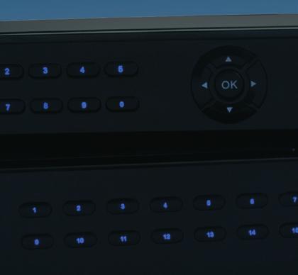
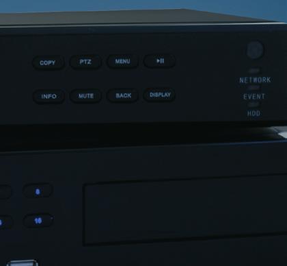
10 Using Front Panel The front panel functions are common for all types of Inspire DVR. INS-DVR04 & INS-DVR08 INS-DVR04P, INS-DVR08P & INS-DVR16P A. Navigation buttons Move around menu screen, control PTZ cameras B. OK button Confirm and accept options C. Power button Switch on / off DVR (requires password) D. Play & pause button Playback and pause recorded video E. Menu button Access engineer menu (requires password) F. PTZ button Enable / disable PTZ mode G. Copy button Access the copy menu H. Display button Change the format of the main display I. Back button Go back one step in menu or stop playback J. Mute button Mute / enable audio & mute alarm K. Info button Display installer information L. Number buttons Select individual channels M. Information lights Display status of HDD, Network, Event N. USB port or copy device(plus versions only) O. CD-DVD eject Open CD-DVD tray (plus versions only) 9
11 Using Infrared Remote The IR remote functions are common for all types of Inspire DVR. A. Navigation buttons Move around menu screen, control PTZ cameras B. OK button Confirm and accept options C. Power button Switch on / off DVR (requires password) D. Play & pause button Playback and pause recorded video E. Menu button Access engineer menu (requires password) F. PTZ button Enable / disable PTZ mode G. Copy button Access the copy menu H. Display button Change the format of the main display I. Back button Go back one step in menu or function J. Mute button Mute / enable audio & mute alarm K. Info button Display installer information L. Number buttons Select individual channels M. Stop button Stop playback of recorded video 10
 C. wheel Zoom from multi camera display to full screen tool bar A. Hide mouse tool bar B. Access engineer menu C. Access playback menu D.")
12 Using a The mouse functions are common for all types of Inspire DVR. A mouse can be used to control all functions of the DVR. A. Left mouse button Double click to zoom to full screen B. Right mouse button Display mouse tool bar (requires password) C. wheel Zoom from multi camera display to full screen tool bar A. Hide mouse tool bar B. Access engineer menu C. Access playback menu D. Access the copy menu E. Enable / disable PTZ mode F. Audio on/off / Mute alarm G. Display installer information H. Select main monitor sequence display (single, quad, eight) I. Display single channel full screen J. Display 4 channels K. Display 9 channels (8 and 16 channel DVR only) L. Display 16 channels (16 channel DVR only) In PTZ mode the mouse can also be used to control the movement of the PTZ camera. 11
13 Using Remote Keypad The Inspire range of DVRs can be controlled from a remote keyboard, the keyboard is connected via RS485 and can be fitted up to 500 metres from the DVR. Up to four separate keyboards can be attached to a single DVR. A. PTZ / DVR Switch from DVR control to PTZ control B. Navigation buttons Move around menu screen C. Joystick (live) Move around menu screen, control PTZ cameras D. Joystick (playback) Forward and back fast and frame step advance E. Enter button Confirm and accept options F. Search & Play button Playback recorded video G. Pause button Pause playback of recorded video H. Menu button Access engineer menu (requires password) I. PTZ button Enable / disable PTZ mode J. Copy button Access the copy menu K. Display button Change the format of the main display L. Back Button Go back one step in menu or function M. Mute button Mute / enable audio & mute alarm N. Info button Display installer information O. Number buttons Select channels (press enter after number) P. Live button Stop playback of recorded video & go to live view 12
14 Power Up To power the DVR up simply connect the 240V mains supply, the DVR will then automatically power up. Once the DVR is powered on the following conditions will be set: The DVR will automatically start recording on all available channels, unless a channel is set to not record (disabled) or the schedule is set to limit recording to Motion Detect, Alarm Event or a Timed Schedule The Video loss alarm will not sound for any channels not used when the DVR is powered up. The video loss alarm will only become active once a channel has a video signal connected The time and date the DVR was powered up will be recorded in the log The DVR will be locked and will require a password to be entered before any user functions become available Power Down To power the DVR down it is recommended that the power button be used. If the power is simply removed by unplugging the 240v main supply this can result in loss of some recordings and the power down not being logged. To power down simply press the power button on the front of the DVR. This will require a password with the correct access level. This prevents unauthorised use of the power button. The default engineer password is The DVR will now power down in an orderly way, it will ensure that the latest video is securely recorded and that the power down time and date is logged together with the user name who initiated the power down. 13
 Press Menu button Right click Enter password (Default 888888) Press Menu button Press")
15 Entering Engineer Menu To enter the engineer menu you must first be logged in to the DVR with Admin rights. To do this and enter the engineer menu do one of the following:- Press OK button Enter password (Default ) Press Menu button Right click Enter password (Default ) Press Menu button Press Enter Enter password (Default ) Press Menu button Remote keypad Make sure the keypad is in DVR mode, (DVR in display on keypad) Press Enter Enter password (Default ) (You must press Enter after each digit e.g. 8, enter, 8, enter) Press Menu button In the login screen you can change the user name that you wish to log in as, use the < > arrow keys or the mouse to change selection. The password can be entered by using the number keys on the front panel or the virtual keyboard using the mouse. After entering the password press OK / Enter to log in. 14

16 Exit Engineer Menu Once you have logged in as a user you will remain logged in until you log out. In some circumstances you may be logged in as a low level user with restricted access, if you then wish to access functions that require a higher level password you will first have to log out then log in again with the correct user name and password. To log out do one of the following:- Press Menu button Press Back button Use Arrow keys to go to Exit & Logout Press OK button Right click Click Menu icon on mouse tool bar Click Exit on the menu Click Exit & Logout Press Menu button Press Menu button Press Back button Use Arrow keys to go to Exit & Logout Press Enter button Remote keypad Make sure the keypad is in DVR mode, (DVR in display on keypad) Press Menu button Press Back button Use Arrow keys to go to Exit & Logout Press Enter button 15
17 Basic Default Settings The following is only the basic settings that the DVR will use when set to factory default or first powered up. There are many other settings and options but for most applications the basic settings will allow the DVR to operate in a normal way. The DVR will always start recording on power up unless the default settings are changed by the engineer. Item Default Setting Language English VGA resolution 800 x 60Hz HDD overwrite On Engineer user name Admin Engineer password PTZ settings All off Normal record quality Normal Normal record resolution 2 CIF Normal record frame rate 15 fps Event record quality Normal Event record resolution 2 CIF Event record frame rate 15 fps Record type Video and Audio Record schedule Continuous Pre and post event recording Off Video loss recording Off IP Address Sub mask Gateway Port 80 Command port 5050 Video port 6050 Mobile port settings Not set Alarm input type Normally open Motion detect Not set Alarm input action Not set HDD error Buzzer only Video loss alarm Buzzer only 16


18 Network Basic Setup The following is only the basic settings that the DVR will use when set to connect direct to PC / Laptop. Requirements PC / Laptop Crossover network cable Connecting For direct cable connection to PC / Laptop a crossover must be used. DVR settings The default network settings will be sufficient, but if you want to change the settings see page 70. Computer settings Depending on your version of windows and your PC / Laptop configuration it may be necessary to change the network settings. Set the PC IP address to Set the PC sub mask to
 The PC will now connect to the DVR and the web browser will display the log in screen for the DVR.")
19 Viewing DVR on Local PC Start Web browser. Enter the address of the DVR in to web browser (e.g. The PC will now connect to the DVR and the web browser will display the log in screen for the DVR. Enter a user name and password Default user name Admin (case sensitive) Default password Once you have entered your log in details and connected to the DVR you will be able to view live cameras, playback recorded video, control PTZ cameras and make changes to the DVR settings. See User instructions for full details on using the web browser remote functions. 18

20 Connect to Internet The following is only the basic settings that the DVR will use when set to connect to the internet. The following assumes that the internet connection is already set up and working and not used as part of an existing network. Requirements ADSL modem router connected to the internet. PC / Laptop to set up modem router. Network patch cable. Connecting Connect the DVR to the modem router using a network patch lead. Connect the PC / Laptop to the modem router using a network patch lead. DVR settings The default network settings should be sufficient, dependant on the router address. These settings can be changed, see page 70. Computer settings Depending on your version of windows and your PC / Laptop configuration it may be necessary to change the network settings. Set the PC IP address to Set the PC sub mask to Set the Gateway to

21 Modem Router Settings In order to view and operate the DVR over the internet you may have to change some settings in the modem router. The settings that require changing are called port forwarding. Unfortunately almost every router has a different method of setup so please refer to your modem router instructions or visit Here you will find detailed instructions on how to configure your modem router. The settings you will need to configure are as follows:- Forward port 5050 to local IP address e.g (the DVR) Forward port 6050 to local IP address e.g (the DVR) Forward port 80 to local IP address e.g (the DVR) Forward port 7050 to local IP address e.g (the DVR) for use with mobile phones Viewing the DVR on Remote PC Start Web browser on remote PC Enter the address of the DVR internet connection in to web browser ( NOTE: this is not the IP address of the DVR. The PC will now connect to the DVR and the web browser will display the log in screen for the DVR. Enter a user name and password Default user name Admin (case sensitive) Default password Once you have entered your log in details and connected to the DVR you will be able to view live cameras, playback recorded video, control PTZ cameras and also make changes to the DVR settings. See User instructions for full details on using the web browser remote functions. 20


22 iphone Viewing Setup All Inspire DVRs can be viewed on a Apple iphone if they are connected to the internet. Requirements Apple iphone 3G, 3Gs, 4G or ipad GPRS, 3G or Wi-fi connection for iphone DVR connected to the internet itunes account ipod application Aplayer (download from itunes FREE) Connecting Connect the DVR to the internet (see page 19 for details). Install iphone application Using the iphone connect to App Store. Search for Aplayer, download and install this application (its free) DVR settings The default network settings will be sufficient, but if you want to change the settings see page

 Default password: 888888 Press back and you DVR settings will be saved Press > button to connect to the")
23 iphone Viewing Viewing the DVR on iphone On the iphone start the Aplayer application Press Settings button Enter the IP address of the DVR in to SERVER IP: (example ) Enter the mobile port number in to PORT: 7050 (this is the DVR default) Enter a user name and password Default user name: Admin (case sensitive) Default password: Press back and you DVR settings will be saved Press > button to connect to the DVR On the iphone application you can only view live images one channel at a time. 22


24 Application Controls A. Move PTZ camera B. PTZ Zoom in & out C. PTZ Focus D. PTZ Aperture E. Select channel to view F. Connect/Disconnect G. Take a snapshot and save to iphone photos H. Scale image I. Select next 4 channels J. Settings Windows Mobile Setup It is possible to view the DVR from Windows Mobile phones and Nokia Symbian mobiles. To connect to the DVR follow these steps: Run your phones Internet browser In the address bar type the DVR IP Address followed by /download.html Example: If the DVR IP Address is then type When the web page loads choose the correct software for your phone and install Once installed run the application and add your DVR settings Click connect to connect the DVR 23
25 Language The Language the DVR on screen display uses can be changed. Use Up and Down arrow keys to navigate to Use UP and Down arrow keys to navigate to Language option Highlight using mouse pointer Click Side arrow buttons to change option Use UP and Down arrow keys to navigate to Language option Options English Chinese More languages available on request 24
26 Set Time & Date Changing the clock will take immediate effect, you do not have to save this change, so caution should be taken with this option. You can change the time and date as well as the format the time and date is displayed in on the monitor and recordings Highlight using mouse pointer Click Side arrow buttons to change option Format Options Time AM/PM Day/Month/Year (12 hour clock) Time Day/Month/Year (24 hour clock) Day - Month - Year Time AM/PM (12 hour clock) Day - Month - Year Time (24 hour clock) 25
27 Daylight Saving Time Setting this option will automatically move the clock forward and back so that the DVR clock is correct during daylight saving time. Select when the clock moves forward and backward by one hour. Start Time is the day the clock will move forward by one hour End Time is the day the clock will move back by one hour The change happens at 1AM on the day set Highlight using mouse pointer Click Side arrow buttons to change option 26
28 Video Standard The Inspire DVRs can be set to operate in any country, if the country used the PAL standard or the NTSC standard. Set PAL for Europe and NTSC for USA Highlight using mouse pointer Click Side arrow buttons to change option Options PAL NTSC Secam 27
29 Set VGA Resolution The Resolution of the VGA main monitor output can be altered to accommodate the type of monitor used. For best results try to match the resolution with the "native" resolution of your monitor. Highlight using mouse pointer Click Side arrow buttons to change option Options 800 x 60Hz 1024 x 60Hz 1280 x 60Hz 1440 x 60Hz 28
30 Key Press Buzzer The key press buzzer (or beep) that sounds every time you press a key can be switched off. Highlight using mouse pointer Click Side arrow buttons to change option Options On Off 29
31 HDD Overwrite There are two ways that the Inspire DVR can use a hard drive (HDD) when recording. It can stop recording when it becomes full or it can overwrite the oldest recordings in an endless loop. Set HDD overwrite to On to overwrite the oldest recording Set HDD overwrite to Off to stop recording when the HDD becomes full Highlight using mouse pointer Click Side arrow buttons to change option Options On Off 30
32 Add User There can be up to eight separate users, each user can have their access rights set individually. One user must be set to Admin (engineer). Adding A User Highlight using mouse pointer Click Side arrow buttons to change option Options User name up to 12 text Password up to digits (0-9) 31
33 User Access Rights Each user can have their access rights changed so that a user will only have access to the part of the system they require. Only Admin can access this feature. Access rights for Admin can't be changed. Setting Access Rights Highlight using mouse pointer Click Side arrow buttons to change option 32

34 User Access Rights Assigning access rights There are two types of access; local and remote. Local access Features and functions on the local DVR Remote access Features that can be accessed over a network First select the user name to change. Then put a Tick in the box next to the item to grant access. Local access Menu Playback Copy PTZ control Change display View hidden cameras Playback hidden cameras Clear alert Shut down Remote access Menu Playback Copy PTZ control Live view View hidden cameras Playback hidden cameras Talk back Alarm outputs Allow access to the engineer menu Allow user to playback recordings Allow user to copy recorded video Allow user to control PTZ cameras Allow user to change the display settings Allow user to view hidden cameras Allow user to playback hidden cameras Allow user to clear an alarm Allow user to power down the DVR Allow access to the engineer menu Allow user to playback recordings Allow user to copy recorded video Allow user to control PTZ cameras Allow user to view live cameras Allow user to view hidden cameras Allow user to playback hidden cameras Allow user to use talk back function Allow user to switch relay outputs on DVR 33

35 Remove User To remove a user select the remove option. Admin account can not be removed. Highlight the account to remove and press remove button. Removing A User Highlight using mouse pointer Click Side arrow buttons to change option 34

36 Change Passwords All users can have their passwords changed. In order to change a password the existing password must be known. A password must be numbers 0-9 but can be any length from 1 to 8 digits. Select the change password option Select the user to change Input old password Input new password Confirm new password 35
37 Change Information Screen The Info screen is a feature where an installer can put in their details, these details can be shown on screen at any time without using a password by pressing the INFO button on the front panel or IR remote. Changing Installer Information Highlight using mouse pointer Click Side arrow buttons to change option Options Enter Installation Company Name Enter Installation Phone number Enter Installation Date Enter last service Date 24 Text 24 Text Date Date 36
38 DVR ID Setting The DVR ID is used to identify the DVR if a remote keyboard is used, if a single DVR is connected to a remote keyboard then the ID can be left unchanged. If two or more DVRs are connected to a single keyboard then each DVR should be given a separate ID number. The ID can be any number from 1 to 255 Highlight using mouse pointer Click Side arrow buttons to change option 37
39 Set DVR Name The DVR name is used to identify the DVR when s are sent and also for identifying the DVR when remote viewing. The DVR name can be any text up to 30 characters Highlight using mouse pointer Click Side arrow buttons to change option 38

40 Channel Name First select individual channel to change or select all channels. Individual will only change the channel selected. All will change all channels to the same settings. Setting The Channel Name The channel name is used for both live and recorded video. Highlight using mouse pointer Click Side arrow buttons to change option Options Up to 16 Text or numbers can be used To reset the Channel name to CH1 (default) select Use default name 39


41 Channel Name Display Options The name OSD option is used for setting the channel name display in live view. First select individual channel to change or select all channels. Individual will only change the channel selected. All will change all channels to the same settings. Setting Channel Name Highlight using mouse pointer Click Side arrow buttons to change option Options On Off The channel name will be displayed in live The channel name is hidden in live (does not affect recorded video) 40
42 Hide Camera The Hide camera option will set a channel to show a graphic instead of the camera in live view. This will not affect recording. First select individual channel to change or select all channels. Individual will only change the channel selected. All will change all channels to the same settings. Highlight using mouse pointer Click Side arrow buttons to change option Options Show Hide Show camera as normal in live view Hide camera in live view. Will also hide over network and playback unless user has authority, see page
43 Display Colour Setting The display colour setting option allows the brightness, contrast, hue and saturation to be adjusted. First select individual channel to change or select all channels. Individual will only change the channel selected. All will change all channels to the same settings. Change Display Colour Settings Highlight using mouse pointer Click Side arrow buttons to change option Options Brightness 0-8 Hide 0-8 Hue 0-8 Saturation

44 Spot Monitor Setting Plus Versions Only The spot monitor can be set so that only selected cameras are shown. Cameras shown on the spot monitor are always full screen, with the monitor switching between selected cameras. The time that a camera is displayed can be set for each camera individually. Change Spot Monitor Settings Highlight using mouse pointer Click Side arrow buttons to change option Options Select cameras to be shown on spot monitor Select time each camera is displayed before switching to next camera Remove a camera Remove all cameras Set default spot monitor settings (All cameras selected switching time 5 sec) 43

45 Mask Setting The mask feature allows an area of a fixed camera to be masked so that it is blank. This is similar to privacy masking in PTZ cameras but the mask is in a fixed position. Setting The Mask Area Use arrow keys to navigate to the green square to the start position & press Ok to lock it in position. Use the arrow keys to adjust the size of the square press OK to mask the area selected. To remove a mask move the green square over a mask and press back. Use the mouse to move the green square to the start position & press and hold the left mouse button and drag the square to the desired area. To remove a mask move the green square over a mask and press right mouse button. Options Four separate masking zones Masking zones can be any size Set masking zones for each channel 44
46 PTZ Setup There are four steps to setting up a PTZ camera, options 2, 3 & 4 can only be set after option 1 (PTZ Protocol) has been set. Settings for PTZ preset positions is optional but options 1,2 & 3 must be set and they must match the settings on the PTZ camera. 1: Select Protocol, This is the language that the DVR will use to communicate with the PTZ camera. Options Pelco P (default) Pelco D 2: Set Baud rate, This is the transmission speed used to communicate with the PTZ camera. It is recommended that a slow speed is used as this will increase the reliability of the communication. Options 1200 baud 2400 baud (default) 4800 baud 9600 baud 3: PTZ ID, Each PTZ camera must have a separate ID this is set in both the PTZ camera and the DVR. e.g. If PTZ on channel 1 is set to ID1, set to ID1 in DVR menu, if PTZ is set to ID2, ID3 etc, then set to corresponding ID in DVR menu. Options 1 to 255 4: PTZ Preset Setup, You can use the DVR to set preset positions on the PTZ camera. It is not necessary to use the DVR if a joystick controller is used with the PTZ camera as setting preset positions can be set much easier using the joystick keyboard. Also only preset positions 1 to 16 can be set using the DVR but when using a joystick keyboard many more preset positions can be programmed, if the PTZ camera used will support them. Options Set Preset 1 to 16 45
47 PTZ Protocol First select individual channel to change or select all channels. Individual will only change the channel selected. All will change all channels to the same settings. Selecting Protocol Highlight using mouse pointer Click Side arrow buttons to change option 46
48 PTZ Baud Rate First select individual channel to change or select all channels. Individual will only change the channel selected. All will change all channels to the same settings. Select Baud Rate Highlight using mouse pointer Click Side arrow buttons to change option 47

49 PTZ ID First select individual channel to change or select all channels. Individual will only change the channel selected. All will change all channels to the same settings. Selecting PTZ ID Highlight using mouse pointer Click Side arrow buttons to change option 48

50 PTZ Preset Setup First select individual channel to change or select all channels. Individual will only change the channel selected. All will change all channels to the same settings. Using a mouse, move the camera to the desired position then select the preset number to store and click Set. Using the front panel, IR remote or remote keyboard, Use the arrow keys to move the PTZ camera, use buttons 1& 2 to zoom in & out Press OK to go to preset save screen. Press number key to set the preset position, and press OK to confirm. 49
51 Time & Date OSD Option The Time and date OSD option allows you to select what is displayed for the time and date in live view. Recorded time and date are not affected by this option. Highlight using mouse pointer Click Side arrow buttons to change option Options None Time only Date only Time & date (default) 50
52 Sequence Time Main This option allows the sequence time to be adjusted for the main monitor if it is used in sequence. The Time set will be the time that the display remains static before switching to the next display. i.e. Setting to 5 seconds will switch between channels on the main monitor every 5 seconds if sequence is selected as the display method. Spot monitor setting is not affected Highlight using mouse pointer Click Side arrow buttons to change option Options Off to 60 seconds 51

53 Display Size Adjust This option allows the main monitor picture to be adjusted to perfectly fit the monitor used. Highlight using mouse pointer Click buttons to change option Options Adjust horizontal size Adjust vertical size Adjust horizontal position Adjust vertical position 52
54 Time OSD Position This option allows the position of the time & date to be moved in live view. Position of recorded time and date is not affected Position of channel name cannot be changed Highlight using mouse pointer Click Side arrow buttons to change option Options Bottom right Bottom left Top right Top left 53
55 Show Record Status This option allows the Recording Icon to be displayed when a channel is recording. It may be switched off if recording indication is not required. This will affect the motion and alarm indicator. This does not affect the way the DVR will record it only switches on or off the icon showing recording status. Highlight using mouse pointer Click Side arrow buttons to change option Options On Off 54
56 Connected Camera Number This option allows the DVR to be set so that some channels are completely disabled. If channel(s) are disabled then all access to them in setup menus will be removed and the channel(s)will not record or monitor video loss. This effectively allows a 16 channel DVR to be converted in to a 14 channel DVR and will save programming time and HDD space. The channels can be switched back on at any time, but the DVR will require a restart after this setting is changed. Highlight using mouse pointer Click Side arrow buttons to change option 55
57 Normal Record Settings The Inspire range of DVRs have two settings for recording, Normal and Event. Normal record settings are used when the DVR is constantly recording or recording according to a time schedule. Event record settings are used if the DVR is reacting to a motion detect event or an alarm input event. This allows the DVR to be recording normally using one set of settings and if an event is detected the record settings will be changed for the duration of the event. Normal record settings have three categories, these settings affect the recording quality and HDD space used. 1: Normal Record Quality This can be set to normal, high or super high. Normal will provide a good quality picture and is economical with HDD space. 2: Normal Resolution The resolution has a large effect of the recorded quality especially if playback is in full screen. There are three settings CIF, 2 CIF and D1 CIF is 360 x 288 pixels, this is equivalent to 1/4 a normal full screen CIF is 720 x 288 pixels, this provides approximately twice the detail as CIF but will require around twice the HDD space D1 is 720 x 576 this is full screen resolution recording it will give the best playback quality but requires up to four times the HDD space as CIF. 3: Normal Frame Rate This setting will not affect the recorded quality but will adjust the number of frames recorded per second. Real time is 25 FPS. Reducing the frames per second will have the biggest effect on the amount of HDD used. A recommended setting for normal quality and good use of HDD space is: Normal Quality CIF Resolution 12 Frames per second A recommended setting for very high quality and heavy use of HDD space is: Super High Quality D1 Resolution 6 Frames per second 56
58 Set Normal Record Quality Set Normal Record Resolution Set Normal Record Frame rate Highlight using mouse pointer Click Side arrow buttons to change option 57
59 Event Record Settings The Inspire range of DVRs has two settings for recording, Normal and Event. Normal record settings are used when the DVR is constantly recording or recording according to a time schedule. Event record settings are used if the DVR is reacting to a motion detect event or an alarm input event. This allows the DVR to be recording normally using one set of settings and if an event is detected the record settings will be changed for the duration of the event. Event record settings have three categories. These settings affect the recording quality and HDD space used. 1: Event Record Quality This can be set to normal, high or super high. Normal will provide a good quality picture and is economical with HDD space. 2: Event Resolution. The resolution has a large effect of the recorded quality especially if playback is in full screen. There are three settings CIF, 2 CIF and D1 CIF is 360 x 288 pixels, this is equivalent to 1/4 a normal full screen CIF is 720 x 288 pixels, this provides approximately twice the detail as CIF but will require around twice the HDD space D1 is 720 x 576 this is full screen resolution recording it will give the best playback quality but requires up to four times the HDD space as CIF. 3: Event Frame Rate This setting will not affect the recorded quality but will adjust the number of frames recorded per second. Real time is 25 FPS. Reducing the frames per second will have the biggest effect of the amount on HDD used. A recommended setting for normal quality and good use of HDD space is: Normal Quality CIF Resolution 12 Frames per second A recommended setting for Very high quality and heavy use of HDD space is: Super High Quality D1 Resolution 6 Frames per second 58
60 Set Event Record Quality Set Event Record Resolution Set Event Record Frame rate Highlight using mouse pointer Click Side arrow buttons to change option 59
61 Record Time Calculator The record time calculator can be used to provide the engineer an estimate of the time the DVR will record for. The calculation is made using the size of the HDD fitted and an average of the normal recording settings. Event record settings are not taken in to account. Scheduled record settings are not taken in to account. Care should be taken using the calculator as it is an estimate and actual times can vary considerably in use. The calculator is provided as an estimate and guide only and should not be relied upon as an accurate indication of record times that will be achieved. 60
62 Disable Recording This option allows the DVR to be set so that some channels are set so that they never record. If channels are set to disable they will not record but all other functions will be available. Highlight using mouse pointer Click Side arrow buttons to change option Options Record Disable 61
63 Record Audio Option This option allows the DVR to be set so audio is recorded along with video. As the inspire range of DVRs only has four channels of audio these are linked to video channels 1 to 4 as follows: Video channel Audio channel 1 Video channel Audio channel 2 Video channel Audio channel 3 Video channel Audio channel 4 Audio recording can be selected as on or off for these channels but audio cannot be recorded with other channels. Highlight using mouse pointer Click Side arrow buttons to change option Options Video Video & Audio 62
64 Audio CH Multi Screen This option set the audio channel that is used when live view is in multi screen mode. i.e. Quad or more cameras displayed at one time. If audio channel 1 is selected this is the audio channel that is used during multi screen mode. In full screen mode audio is automatically switched to the corresponding input. If the option is set to NOT SET then no audio will be heard in multi screen display. Highlight using mouse pointer Click Side arrow buttons to change option Options 1 to 4 Not Set 63
65 Record OSD Option This option will set the type of OSD that is embedded in to the recording on each channel. The time and date as well as the channel name can be recorded along with the video, however once recorded it cannot be switched off during playback as it becomes part of the recording. The position of the channel name is fixed in the top left corner and the position of the time and date is fixed in the bottom right corner. Highlight using mouse pointer Click Side arrow buttons to change option Options None Time & Date Camera Name Camera name & Time and Date 64

66 Record Schedule The record schedule is used to programme when and how the DVR will record There are five settings for the schedule: Disable Continuous (default) Motion and alarm Motion Alarm Disables recording Records continually Record only during Motion or alarm events Record only during motion events Record only during alarm events The DVR can be set by day and hour so it is possible to have different recording parameters on different days and at different times. Use number keys to select the type of recording Use OK key to change option Use number keys to select the type of recording Use OK key to change option Highlight using mouse pointer Click and drag mouse arrow to change option Use number keys to select the type of recording Use OK key to change option 65
67 Pre Event Recording Pre Event recording will set the DVR to record 10 seconds of video prior to either a motion or alarm event. This is only required if the DVR is set to record only in motion or alarm, in continuous the DVR will already be recording. Highlight using mouse pointer Click Side arrow buttons to change option Options On Off 66
68 Post Event Recording Post Event recording will set the DVR to record 10 seconds of video after a motion or alarm event. This is only required if the DVR is set to record only in motion or alarm, in continuous the DVR will already be recording. Highlight using mouse pointer Click Side arrow buttons to change option Options On Off 67
69 Water Mark The Water Mark setting, if set to on, will add a hidden mark to all recordings. If during playback tampering with the video is detected a warning will be given. Highlight using mouse pointer Click Side arrow buttons to change option Options On Off 68
70 Video Loss Recording Video loss recording will set the DVR to record 10 seconds of video prior to a video loss alarm. This is only required if the DVR is set to record only in motion or alarm, in continuous the DVR will already be recording. Highlight using mouse pointer Click Side arrow buttons to change option Options On Off 69
71 Network Type There are two types of network settings that can be used with inspire DVRs, Static IP and DHCP. Static IP is a manually assigned fixed setting. DHCP is where the network settings are assigned by a DHCP server on the network, this is usually a router. For most applications a static IP is best as this will not allow the network settings to be altered, and will prevent problems with access from a remote location. Highlight using mouse pointer Click Side arrow buttons to change option Options On Off 70
72 Network Details If the network type is set to DHCP then these settings will be automatically set by the DHCP server. If the network type is set to Static IP then these details will need to be set manually. These settings need to be set in accordance with the network the DVR is being connected to, for help with this consult the network administrator IP address: This is a unique address on the network the default setting is usually sufficient for most simple networks. however care should be taken to ensure that no other device on the network has the same address. Sub net mask: This is usually set to if this needs to be changed consult the network administrator. Gateway: This is the IP address of the gateway to the internet, this is usually the router on simple networks and is usually set to Primary DNS: This is the IP address of the domain name server, this is used to look up an IP address for a named domain. The DVR will need this if , DDNS or time synchronisation is to be used. Otherwise this does not need to be set for network access Secondary DNS: This is the IP address of the secondary domain name server, this is used to look up an IP address for a named domain. The DVR will need this if , DDNS or time sync are to be used. Otherwise this does not need to be set for network access 71
73 There are four port settings that the DVR uses to communicate on a network. HTTP Port Command Port Video Port Mobile Port The Http port is used to send web pages from the DVR to a remote computer. Port 80 is the standard port for web browsers such as Internet Explorer. This can be changed for security if required This is used to send and receive commands from remote computers This is used to stream video to remote computers This is used to stream video to windows mobile or iphone devices All the ports can be changed but care should be taken as the port settings in the DVR must match open ports in the router, and the router must be set for port forwarding for remote access across the internet. For details on setting your router for port forwarding see 72

74 Settings If the DVR is connected to the internet it can be set to send an to up to 5 different people. The will contain details of the DVR and the event that triggered the . In addition if the event is a alarm input or motion detect a snapshot of the event will be attached. The will be sent if various events take place, these must be set in the event section HDD Full HDD Fail Video Loss Alarm Input triggered Motion Detect triggered To set up you must have set the DNS in the network settings. You will need to have all the details for the outgoing account as well as the recipients address. Please ask the network administrator for these details. 73
75 PPPOE Settings PPPOE is only required if the DVR is connected direct to an ADSL modem and not to an ADSL router or existing network. In the UK it is not common for ADSL modems to be used as most are combined with a router that will perform the PPPOE function. These settings need to be set in accordance with the ADSL network and the modem that is being used, for help with this consult the network administrator Highlight using mouse pointer Click Side arrow buttons to change option 74
76 DDNS Settings The DDNS function is used when the ADSL connection is not a static IP type, this is known as dynamic IP. In this case you will need to set up DDNS so that you can always connect to the DVR from a remote location. The DVR comes with some default settings but you will have to create an account with one of the DDNS services before you can use the DDNS function. For more details and help setting up DDNS consult the network administrator Highlight using mouse pointer Click Side arrow buttons to change option 75
77 Dual Stream Function The dual stream function is designed to improve remote viewing over a network. There are three settings: Disable Prioritise Quality Prioritise FPS This will switch off Dual Streaming and the video transmitted across the network will be at the same settings as the record setting. This may cause poor network performance if the recording settings are set to D1 and high quality This will switch on dual stream and set the transmitted video to a good quality but the frame rate may be slower on poor networks and across the internet This will switch on Dual stream and set the transmitted video to be sent at the best possible frame rate, however the picture quality may be lower across a poor network or across the internet Highlight using mouse pointer Click Side arrow buttons to change option 76
78 Internet Time Synchronisation The Time Synchronisation function will synchronise the DVR clock to an atomic clock on the internet. This function requires an internet connection and that DNS is set up correctly. You must first select an atomic clock (time server) to synchronise with, there are many available in different parts of the world. The default time server should provide a reliable clock. You can set the interval the DVR will check and synchronise the clock, the options are: Daily Weekly Monthly You can also set the time zone you are in, this is very important as all time servers will provide a time signal in GMT. For the UK you should set the server for GMT 00:00. Daylight saving time is automatically added by the DVR according to the settings in the system menu, see page
79 Alarm Input Type This option will set the alarm input to either normally open (N.O) or normally closed (N.C) Setting to N.O sets the alarm input to be inactive until it is connected to 0 volts Setting to N.C sets the alarm input to be active if 0 volts is removed Highlight using mouse pointer Click Side arrow buttons to change option 78
80 Alarm Output Duration This sets the length of time the alarm output is active after an alarm is triggered. There are two options: Latch until reset 1 to 60 seconds The alarm output is not automatically triggered when an alarm input is active this must be set up in alarm actions. Highlight using mouse pointer Click Side arrow buttons to change option 79
81 Alarm Actions Setting alarm actions is essential if you intend to use alarm inputs. There are five possible actions the DVR can take if an alarm input is triggered: Record PTZ Preset Alarm Out Buzzer This will set the ticked channel to record if the DVR is not already recording. It is possible to have multiple channels recording if a single alarm input is active This will set the DVR to instruct a PTZ camera to move to a preset position if an alarm input is active This will set the DVR to trigger an alarm output (relay) if an alarm input is active This will sound the internal buzzer if an alarm input is active, this can be silenced (muted) by the user. This will set the DVR to send an together with a snapshot of the channel set to record if an alarm input is active There are a selection of tick boxes to activate all the possible actions. If no boxes are ticked no action will be taken apart from an entry in the DVR log. 80
82 Full Screen on Alarm This will set the DVR to display the active channel in full screen on the main monitor if an alarm input is activated. Alarm input 1 will always display video channel 1 etc. There are three options: Off Latch until reset 1 to 10 seconds Highlight using mouse pointer Click Side arrow buttons to change option 81
83 Motion Detect Setup The motion detection setup is in two stages, first it must be enabled and a sensitivity level set. There are three sensitivity settings: Low sensitivity Medium Sensitivity High Sensitivity Great care should be used when selecting a sensitivity, as setting a high sensitivity with external cameras can cause a lot of activations in bad weather, but setting a low sensitivity for internal cameras can cause motion to be missed. Highlight using mouse pointer Click Side arrow buttons to change option 82

84 The second part of setting up motion detect is selecting the area that is monitored. This is set up for each individual camera and objects such as trees can be deselected to reduced the number of false detections. The motion area is split in to a 12 x 16 grid with 192 individual detection areas. Each area may be deselected. Use Arrow keys to move the green square to the position & press OK to deselect, press ok to reselect To exit press back Use the mouse to move the green square to the start position & press and hold the left mouse button and drag the square to the desired area to select. To deselect simply repeat the process. To exit press right mouse button Purple squares are used by motion detect Clear squares are deselected 83
85 Motion Output Duration This sets the length of time the motion detect event is active after motion is detected. There are two options: Latch until reset 1 to 60 seconds The motion detect actions are not automatically triggered when motion is detected these must be set up in motion detect actions. Highlight using mouse pointer Click Side arrow buttons to change option 84
86 Motion Detect Actions Setting motion detect actions is essential if you intend to use motion detect. There are five possible actions the DVR can take if motion detect is triggered: Record PTZ Preset Alarm Out Buzzer This will set the ticked channel to record if the DVR is not already recording. It is possible to have multiple channels recording if motion is detected This will set the DVR to instruct a PTZ camera to move to a preset position if motion is detected This will set the DVR to trigger an alarm output (relay) if motion is detected This will sound the internal buzzer if motion is detected, this can be silenced (muted) by the user. This will set the DVR to send an together with a snapshot of the channel set to record if motion is detected There are a selection of tick boxes to activate all the possible actions. If no boxes are ticked no action will be taken apart from an entry in the DVR log. 85
87 Full Screen on Motion This will set the DVR to display the active channel in full screen on the main monitor if motion is detected. There are three options: Off Latch until reset 1 to 10 seconds Highlight using mouse pointer Click Side arrow buttons to change option 86
88 Video Loss Actions Setting video loss actions is essential if you intend to use video loss. There are five possible actions the DVR can take if video loss is detect is triggered: Record PTZ Preset Alarm Out Buzzer This will set the ticked channel to record if the DVR is not already recording. It is possible to have multiple channels recording if video loss is detected This will set the DVR to instruct a PTZ camera to move to a preset position if video loss is detected This will set the DVR to trigger an alarm output (relay) if video loss is detected This will sound the internal buzzer if video loss is detected, this can be silenced (muted) by the user This will set the DVR to send an together with a snapshot of the channel set to record if video loss is detected Video loss is not detected until a video signal is connected to a channel and then removed. There are a selection of tick boxes to activate all the possible actions. If no boxes are ticked no action will be taken apart from an entry in the DVR log. 87
89 HDD Full Actions Setting HDD full actions is essential if you intend to use the HDD full alarm. There are three possible actions the DVR can take if the HDD becomes full: Alarm Out Buzzer This will set the DVR to trigger an alarm output (relay) if the HDD becomes full. This will sound the internal buzzer if HDD becomes full, this can be silenced (muted) by the user. This will set the DVR to send an if HDD becomes full. The HDD will only become full if HDD overwrite is set to off. There are a selection of tick boxes to activate all the possible actions. If no boxes are ticked no action will be taken apart from an entry in the DVR log. 88
90 HDD Error Actions Setting HDD error actions is essential if you intend to use the HDD error alarm. There are three possible actions the DVR can take if the HDD becomes faulty: Alarm Out Buzzer This will set the DVR to trigger an alarm output (relay) if the HDD becomes faulty This will sound the internal buzzer if HDD becomes faulty, this can be silenced (muted) by the user. This will set the DVR to send an if HDD becomes faulty. The HDD will only become full if HDD overwrite is set to off. There are a selection of tick boxes to activate all the possible actions. If no boxes are ticked no action will be taken apart from an entry in the DVR log. 89

91 View Log The Inspire DVR will log many activities including the following: System power up System power down Power failure User log on the system User log out of the system User log in from remote location User log out from remote location Changes to system configuration Alarm input triggered Motion detected Video Loss Password changes Playback HDD full HDD errors Copy The log can be viewed as pages. Each page is 9 events long with each event having a time and date stamp as well as the current user logged in when the event occurred. 90
92 Copy Log The entire log can be copied to a USB memory stick and viewed in Internet Explorer. To copy the log plug a USB memory stick in to the DVR USB socket either on the front or rear of the DVR. Select Copy Log and the DVR will check the USB device. You then have the the file name. The log is copied in HTML format and can be viewed in Internet Explorer. 91

93 Format HDD WARNING USE THIS OPTION WITH CARE ALL RECORDINGS WILL BE ERASED To completely erase or prepare a new HDD for use it must be formatted. If a single HDD is fitted recording is suspended during format and will automatically resume when formatting is complete. If more than one HDD is fitted recording will continue during formatting. Highlight the HDD to format and click Format to start the process. 92
94 Software Upgrade The inspire range is designed to be upgraded to add new features as they become available. Service packs may be sent out from time to time in the form of a USB memory stick. During an upgrade recording is suspended. After an upgrade all the settings programmed by the engineer are retained and only new features will need to be programmed. To upgrade plug a USB memory stick containing the upgrade service pack in to the DVR USB socket either on the front or rear of the DVR. Select Software Upgrade and the DVR will check the USB device. The DVR will automatically detect the upgrade file on the USB device and after clicking start the upgrade process is fully automatic. The upgrade will take around 2 to 3 minutes during which time the DVR will reboot. 93
95 Copy Settings to USB The entire system settings can be copied to a USB memory stick and loaded in to another DVR or kept on record. To copy the system settings plug a USB memory stick in to the DVR USB socket either on the front or rear of the DVR. Select Copy settings to USB and the DVR will check the USD device. You then have the the file name. 94
96 Load Settings from USB The entire system settings can be loaded from a USB memory stick and this will overwrite the current settings. To load the system settings plug a USB memory stick containing a saved settings file in to the DVR USB socket either on the front or rear of the DVR. Select Load settings from USB and the DVR will check the USB device. You then have the the file name. During an upgrade recording is suspended. The DVR will automatically detect the settings file on the USB device and after clicking start the load process is fully automatic. Loading will take around 2 to 3 minutes during which time the DVR will reboot. 95
97 Load Default Settings This will reset all engineer settings to the factory default. Select Load default settings. Click Yes to proceed. During loading recording is suspended. Loading will take around 2 to 3 minutes during which time the DVR will reboot. 96
98 DVR Configuration Information DVR configuration information can be displayed, this will show the basic settings for the hardware. HDD Capacity Hardware Version Software Version IP Address Gateway MAC Address Recording Times The total HDD capacity (Sum of all HDDs fitted) Main PCB version Operating system version Network setting Network setting Network setting Earliest recording and last recording (if schedules are used their may be gaps in the recording where no recording has taken place. 97

99 C O P S e c u r i t y, D e l p h N e w R o a d, Dobcross, OL3 5BG England tel: fax: sales@cop-eu.com web:
CCTV42 System2 DVR Quick Start Guide 4/8/16-Ch DVR
 CCTV42 System2 DVR Quick Start Guide 4/8/16-Ch DVR If you have purchased a DVR / Hard drive package from us then we will have already installed the hard drive(s) and configured the basic settings on your
H.264 Network DVR. Quick Start. GUI Display with USB Mouse Control 336Z
 336Z H.264 Network DVR Quick Start GUI Display with USB Mouse Control Please read instructions thoroughly before operation and retain it for future reference. For the actual display & operation, please
Pro71600N3 NVR User Manual
 Pro71600N3 NVR User Manual User Information Admin User Name: Admin Password: IP Address: System Name: Table Of Contents 1. Menu Operation...4 1.1 Main Menu...4 2. Start & Shutdown System...5 2.1 Start
H.264 Network DVR. Quick Start
 341Z H.264 Network DVR Quick Start GUI Display with USB Mouse Control Please read instructions thoroughly before operation and retain it for future reference. For the actual display & operation, please
CONTENTS Chapter 1: DVR Features... 4 Chapter 2: Overview... 5 Chapter 3: Starting the DVR... 8
 1 CONTENTS Chapter 1: DVR Features... 4 Chapter 2: Overview... 5 2.1 Front Panel... 5 2.2 Rear Panel... 6 2.3 Remote Control... 7 Chapter 3: Starting the DVR... 8 3.1 Firmware Version... 8 3.2 Detecting
H.264 Network DVR. Quick Start
 H.264 Network DVR Quick Start GUI Display with USB Mouse Control Please read instructions thoroughly before operation and retain it for future reference. For the actual display & operation, please refer
Blue v2 INSPIRE DVR RANGE USER MANUAL
 INSPIRE Blue v2 DVR RANGE USER MANUAL Contents Logging into the DVR Mouse menu Live viewing Playback Smartphone viewing setup Smartphone viewing Copy to USB/Disc Using Cop player 2 playback software Using
Pro7804N1 NVR User Manual
 Pro7804N1 NVR User Manual Pro7804N1 User Manual BW R6.indd 1 User Information Admin User Name: Admin Password: IP Address: System Name: Table Of Contents 1. Menu Operation...4 1.1 Main Menu...4 2. Start
Pro7400H1 Hybrid DVR User Manual
 Pro7400H1 Hybrid DVR User Manual User Information Admin User Name: Admin Password: IP Address: System Name: Table Of Contents 1. Menu Operation... 4 1.1 Main Menu... 4 2. Start Up/Shutdown System... 5
Quick Start Guide 4/8-CH DVR
 Quick Start Guide 4/8-CH DVR 1 1. Install Hard Drive &DVD Writer 1.1 Install Hard Drive Notice: 1. this series support one SATA hard drives. Please use the hard drive the manufacturers recommend specially
960H H.264 DVR Setup Guide
 Package Content 960H H.264 DVR Setup Guide Inspect the packaging carton. Make sure the 960H H.264 DVR is properly delivered. Remove all items from the box and make sure the box contains the following items.
TruVision DVR 60 Quick Start Guide
 Content Package contents 1 Installation environment 1 Setting up the TVR 60 1 Connecting the devices 2 Turning on and off the TVR 60 2 Operating the TVR 60 3 DDNS settings 5 Live mode 5 Quick Archive 5
JVS-D7216 Standalone DVR User Manual
 Menu JVS-D7216 Standalone DVR User Manual JVS-D7216 Standalone DVR Instructions 1. Introduction..4 1.1 Product Description...4 1.2 Features..4 1.3 Specifications...4 2. Product Features....6 2.1 Panel
USER S MANUAL GV-DVR1042. Real Time DVR System. Stand Alone 4 Channel.
 USER S MANUAL GV-DVR1042 Stand Alone 4 Channel Real Time DVR System www.gviss.com 1 B E F O R E I N S T A L L A T I O N - - - - - - - - - - - - - - - - - - - - - - - - - - - - - - - - - - - - - - - - -
Quick Start Guide 4/8/16-Ch DVR
 Quick Start Guide 4/8/16-Ch DVR 1 1. Install Hard Drive &DVD Writer 1.1Install Hard Drive Notice: 1.This series support one SATA hard drive. Please use the hard drive the manufacturers recommend specially
PAL 4-camera AHD DVR PAL 8-camera AHD DVR PAL 16-camera AHD DVR
 391 115 391 116 391 117 PAL 4-camera AHD DVR PAL 8-camera AHD DVR PAL 16-camera AHD DVR User manual LE08198AA-01FV-15W04 en Contents 1 Product description... 5 1.1 Front view... 5 1.2 Rear view... 6 1.3
Chapter 1 Features FEATURES
 Chapter 1 Features Operation Playback, recording and network transmission simultaneously Real time full screen or quad screen display 2X digital zoom and Picture-in-picture display Easy operations by shuttle
NVR&IPCAM USER MANUAL V1.0 (USER MANUAL) V1.0. Thanks for choosing our products, please read this manual carefully before use!
 V1.0. Thanks for choosing our products, please read this manual carefully before use!") NVR&IPCAM (USER MANUAL) V1.0 Thanks for choosing our products, please read this manual carefully before use! NOTICE Installation condition 1) In order to ensure your rights, please read this manual carefully
NVR&IPCAM (USER MANUAL) V1.0 Thanks for choosing our products, please read this manual carefully before use! NOTICE Installation condition 1) In order to ensure your rights, please read this manual carefully
Quick Start Guide 4/8/16-Ch DVR
 Quick Start Guide 4/8/16-Ch DVR 1 1. Install Hard Drive &DVD Writer 1.1Install Hard Drive Notice: 1. Support two SATA hard drives. Please use the hard drive the manufacturers recommend specially for security
4CH/ 8CH/ 16CH Digital Video Recorder
 4CH/ 8CH/ 16CH Digital Video Recorder DVR204B/ 208B/ 216B INSTRUCTION MANUAL DIRECTORY CHAPTER 1 Hard Disk Installing (Standard shipping products include neither HDD or R/W)...2 CHAPTER 2 Panel Appearance...4
VMS-A1 Client Software. User Manual
 VMS-A1 Client Software User Manual Contents Contents... 2 Chapter1. Overview... 4 1.1 Description... 4 1.2 Features & Functions... 4 Chapter2. Update Info... 6 Chapter3. Starting VMS-A1... 7 3.1 Installing
H.264 4/8/10/16-Channel High-Definition DVR Quick Start Guide
 H.264 4/8/10/16-Channel High-Definition DVR Quick Start Guide Products: BLK-HD4D, BLK-HD4E, BLK-HD8D, BLK-HD10D, BLK-HD16D BLK-HD4E (upper) BLK-HD4D and BLK-HD8D (middle) BLK-HD10D and BLK-HD16D (lower)
R4, R8, R16 Digital Video Recorders Quick Setup Guide
 R4, R8, R16 Digital Video Recorders Quick Setup Guide This guide provides instructions to initially setup the R16 (16 channel) digital video recorders (DVR). The DVR supports these advanced features: 2
Quick Start Guide 4/8/16/24-Ch DVR
 Quick Start Guide 4/8/16/24-Ch DVR 1.1 Install Hard Drive 4/8/16/24-CH DVR Quick Start Guide Notice: 1.4/3/16-ch DVR supports one SATA hard drive. 24-ch DVR supports three SATA hard drives. Please use
SmartWatch Eco/Eco Compact
 SmartWatch Eco/Eco Compact Digital Video Recorders SmartWatch Eco SmartWatch Eco Compact Quick User Guide Index Box Contents...3 Front Panel Controls...4-5 SmartWatch Eco Compact...4 SmartWatch Eco...5
follow BLK-D20xx00D RQ 2011 DIGIOP, Inc.
 H.264 4/8/16 Channel DVR Quick Start Guide Products: BLK-DH2004 400D, BLK-DH200800D, BLK-DH201600D PLEASE READ THIS GUIDE BEFORE USING YOUR RECORDER, and always the instructions for safety and proper use.
Quick Start Guide 4/8/16-CH DVR.
 Quick Start Guide 4/8/16-CH DVR 1. Install Hard Drive &DVD Writer 1.1 Install Hard Drive Notice: 1. Support two SATA hard drives. Please use the hard drive the manufacturers recommend specially for security
HLong Asia Industrial
 SDI DVR Stand alone digital video recorder HLong Asia Industrial Thank you for using the company's products! This manual describes only the host functions basic operation. Product design and specification
Digital Video Recorder User Manual. DVR User Manual. For H channe/ 8-channel/16-channel Digital Video Recorder All rights reserved
 DVR User Manual For H.264-4-channe/ 8-channel/16-channel Digital Video Recorder All rights reserved i CAUTION Please read this user manual carefully to ensure that you can use the device correctly and
SPY-DVR4HYB & SPY-DVR8HYB SPY-DVR4HYB2ND & SPY-DVR8HYB2ND
 SPY-DVR4HYB & SPY-DVR8HYB SPY-DVR4HYB2ND & SPY-DVR8HYB2ND Instructions 1.0 INTRODUCTION 1.1 Main menu 2.0 SPLIT SCREEN 3.0 SYSTEM SETUP 3.1 General Setup 3.2 Time Setup 3.3 HDD Setup 3.4 Screen Setup 3.5
User s Manual of DVR ULTIMAX. Remote Client Software V wersja 2.40
 User s Manual of DVR ULTIMAX Remote Client Software V 4.0.1 ULTIMAX-304 ULTIMAX-308 ULTIMAX-316 ULTIMAX-504 ULTIMAX-508 ULTIMAX-516 ULTIMAX-704 ULTIMAX-708 ULTIMAX-716 wersja 2.40 Index 1 Software Install,
Lite H.264 DVR Setup Guide
 Package Content Lite H.264 DVR Setup Guide Inspect the packaging carton. Make sure the Lite H.264 DVR is properly delivered. Remove all items from the box and make sure the box contains the following items.
QSD2308L/QSD2316L DVR User s Manual
 QSD2308L/QSD2316L DVR User s Manual NOTE: We use two different front panel designs on these models. They have the same function buttons but they are arranged differently. Please match the front panel on
Analog High Definition DVR. Stand alone digital video recorder. User Manual H.264 AHD DVR
 Analog High Definition DVR Stand alone digital video recorder User Manual H.264 AHD DVR WARNING To reduce the risk of fire or electric shock, do not expose this appliance to rain or moisture. All the safety
DHE-04 DHE-08 DHE H H.264 DVR 4 / 8 / 16 CH. Quick Setup Guide PACKAGE CONTENTS A. B. C. D. E. F. G. H. Inside the DVR I.
 960H H.264 DVR 4 / 8 / 16 CH. Quick Setup Guide DHE-04 DHE-08 DHE-16 PACKAGE CONTENTS A. One (1) DHE-04 / DHE-08 / DHE-16 DVR B. One (1) Remote Controller C. Two (2) AAA Battery for Remote Controller D.
4CH Real Time DVR. User Guide INFORMATION MAY CHANGE WITHOUT NOTICE. Digital Video Recorder
 User Guide INFORMATION MAY CHANGE WITHOUT NOTICE. Table of Contents Caution... 4 Package Contents... 4 Introduction... 5 1. Product Overview...5 2. Front Panel...5 3. Rear Panel...6 4. IR Remote Controller
DDR-08 DDR-16 Full D1 Realtime H.264 DVR 8 / 16 CH. Quick Setup Guide
 DDR-08 DDR-16 Full D1 Realtime H.264 DVR 8 / 16 CH. Quick Setup Guide PACKAGE CONTENTS A. One (1) DDR-08 / DDR-16 DVR B. One (1) Remote Controller C. Two (2) AAA Battery for Remote Controller D. One (1)
Standard H.264 DVR Setup Guide
 Package Content Standard H.264 DVR Setup Guide Inspect the packaging carton. Make sure the Standard H.264 DVR is properly delivered. Remove all items from the box and make sure the box contains the following
NUBIX H.264 DVR Setup Guide
 Package Content NUBIX H.264 DVR Setup Guide Inspect the packaging carton. Make sure the NUBIX H.264 DVR is properly delivered. Remove all items from the box and make sure the box contains the following
DVR User s Manual. For H FPS /8-channel digital video recorder All rights reserved. Rev
 QSDT8DP DVR User s Manual For H.264-240 FPS /8-channel digital video recorder All rights reserved Rev 120209 i QSDT8DP User s Manual CAUTION Please read this user manual carefully to ensure that you can
Chapter 3 Operating instructions
 Chapter 3 Operating instructions Summary This chapter describes the how to control and navigate through the TVR 30 s menus and options. Content Control interfaces 10 Controlling the TVR 30 10 Front panel
AMDV960H4 User Manual
 s AMDV960H4 User Manual AMDV960H4 User Manual Version 1.3.2 www.amcrest.com 1 TABLE OF CONTENTS 1 PRODUCTION 4 1.1. Product Key Features 4 1.2. Front Panel Controls 5 1.3. USB Mouse 6 1.4. Soft Keyboard
Stand Alone Type. Digital Video Recorder USER S MANUAL. XRS 1000 Series. This manual is written based on 1016
 Stand Alone Type Digital Video Recorder USER S MANUAL XRS 1000 Series This manual is written based on 1016 Index CHAPTER 1 Specification & System organization 1. Product Contents List --------------------------------------------------------
SPY-DVR4KIT1/SPY-DVR4KIT2
 SPY-DVR4KIT1/SPY-DVR4KIT2 SPY-DVR4KIT1 (1) 4 channel DVR with 500GB Hard Drive (2) Plastic mini dome cameras (2) Weather resistant mini bullet cameras (1) 120v to 12v AC/DC power supply (1) 5 way splitter
16CH Digital Video Recorder INSTRUCTION MANUAL
 16CH Digital Video Recorder INSTRUCTION MANUAL Trademarks and registered trademarks Microsoft, Windows 2000, Windows XP, Internet Explorer are registered trademarks of Microsoft Corporation in the U.S.
TruVision NVR 50 Quick Start Guide
 TruVision NVR 50 Quick Start Guide Content Contact information 1 Package contents 1 Installation environment 1 Quick install 1 First-time use 1 TVN 50 front and back panels 2 Operating the NVR 50 4 Web
Digital Video Recorder User Manual. DVR User Manual. For H channel/ 8-channel/16-channel Digital Video Recorder All rights reserved
 DVR User Manual For H.264-4-channel/ 8-channel/16-channel Digital Video Recorder All rights reserved i CAUTION ii Please read this user manual carefully to ensure that you can use the device correctly
DVR DVR VENEZIA series
 DVR DVR VENEZIA series Main features - Real Esaplex (Recording, Live, Play, Control, Backup, Network) - Quick connection by mobile/ PDA phone without using any software - H264 compression - Real time Recording,
Video Web Server. User s s Manual MPEG-4 VIDEO WEB SERVER. Please read instructions thoroughly before operation and retain it for future reference.
 13 Video Web Server MPEG-4 VIDEO WEB SERVER User s s Manual Please read instructions thoroughly before operation and retain it for future reference. 733_V0.95 Thank-You Note Before You Get Start First
Trouble Free DDNS Setup
 H.264 Compression Technology, Up to 120fps 1080P for 4CH Real Time 4CH HD-SDI H.264 Stand Alone Video Recorder CMS (Central Management So ware) supports Mul ple DVR for free Mobile Surveillance: iphone,
H.264 Dual Stream Network DVR 8 Channel & Digital Video Recorder USER MANUAL. Model #: QT528
 H.264 Dual Stream Network DVR 8 Channel CIF@240fps & D1@240fps Digital Video Recorder USER MANUAL Model #: QT528 www.q-see.com Rev 12/6/2010 CAUTION Please read this user manual carefully to ensure that
HDMI mobile phone monitoring H.264 Central Management Software Delta
 The DA-DVRLEA LC series - Slim line design DVR that supports HDMI and mobile phone monitoring functions. H.264 encoding cost effective DVR suit your needs, DA- DVRLEA LC series DVR brings standard standalone
LOREX CLIENT Remote Agent Software
 LOREX CLIENT Remote Agent Software Instruction Manual English Version 1.0 MODEL: L500 Series www.lorexcctv.com Copyright 2006 LOREX Technology Inc. Table of Contents Table of Contents About the Lorex Client...
IP WEB User Manual V2.0
 IP WEB User Manual V2.0 Please read carefully before installing or contacting your supplier. The information contained at the time of printing is correct, but is subject to change without notice. This
GRAND IP VIDEO SERVER PRO. User s Manual INDEX
 INDEX GRAND IP VIDEO SERVER PRO Video & Audio Transmission/ iphone Web Browser Support User s Manual ISSUE:Mar 16, 2010 1. Package Contents.... 1 2. Introduction.... 1 3. System Requirements...... 1 4.
DVR User Manual. For H.264-4/8/16-channel digital video recorder All rights reserved
 DVR User Manual For H.264-4/8/16-channel digital video recorder All rights reserved CAUTION Please read this user manual carefully to ensure that you can use the device correctly and safely We do not warrant
H Channel Digital Recording System. User Manual
 H.264 4 Channel Digital Recording System V X H 2 6 4-4 User Manual CONTENTS Before installing 1 Key features 2 Front panel description 3 Rear panel description 4 Getting started 5 Connect and switch on
User Manual VXM4-8. MPEG4 8 Channel Digital Recording System HOLD DISPLAY SEQ PANIC RW. ZOOM OUT FF. ZOOM IN ZOOM LOCK ARCHIVE PTZ SETUP SEARCH
 DISPLAY SEQ PANIC ZOOM LOCK ARCHIVE PTZ SETUP SEARCH RETURN ENTER PWR REC NET RW. ZOOM OUT HOLD FOCUS IRIS NEAR FAR CLOSE OPEN FF. ZOOM IN MPEG4 8 Channel Digital Recording System VXM4-8! ± + 1 2 3 4 5
DS-9000 Series Hybrid Net DVR
 DS-9000 Series Hybrid Net DVR Overview DS-9000 series net DVR is the Hybrid DVR of a new generation designed by HIKVISION. The product combines various patents, along with advanced IT technologies such
HIGH STORAGE MODELS WITH CD-RW DRIVE
 208 CPD HIGH STORAGE MODELS WITH CD-RW DRIVE CPD505HC_CPD507HC_QUICK_V1.2 1. OVERVIEW 1.1 Product Description With the high storage capacity feature, this MPEG-4 DVR model is designed to accommodate up
AVE DR16X / AVE DR8X Quick Installation Guide
 AVE DR16X / AVE DR8X Quick Installation Guide Package Content Inspect the packaging carton. Make sure your AVE DR16X / AVE DR8X is properly delivered. Remove all items from the box and make sure the box
4CH H.264 Multiplex DVR
 4CH H.264 Multiplex DVR User Manual VER.:1.0, P/N: R040199A This symbol is intended to alert the user to the presence of unprotected Dangerous voltage" within the product's enclosure that may be strong
Figure 2: Front panel controls For detailed information on all the button functions, please refer to the user manual.
 TruVision NVR 22 (S/P) Quick Start Guide Figure 1: Back panel connections (TVN 22S shown) 1. Connect one audio input to RCA connectors. 2. Connect to an HDTV. The HDMI connection supports both digital
Quick Installation Guide
 Quick Installation Guide For Bundles Featuring the QC4098 or QC4096 Network DVR 8 and 6 Channel H.64 Compression All-in-One DVRs with Variable CIF and D Recording Options PART - PACKAGE CONTENTS QC4098
4Ch Real time / Triplex / Mux Stand Alone DVR
 4Ch Real time / Triplex / Mux Stand Alone DVR User s Manual VER 1.2 VSD-31 4 Channel Stand Alone DVR USB Backup available The most stable and reliable real stand alone Digital Video Multiplex Recorder
Appendix A. esync DVR Manual Appendix A. FCC Compliance Statement WARNING. Revision A esync Manual esync
 Appendix A Appendix A FCC Compliance Statement Model Name: esync Series (SSA-1648e, SSA-0824e, SSA-0424e). This device complies with Part 15 of the FCC Rules. Operation is Subject to the following two
TVR 12 Quick Start Guide
 TVR 12 Quick Start Guide Figure 1: Back panel connections 1. Loop through for up to 16 analog cameras (depends on DVR model). 2. Connect to a RS-232 device. 3. Connect up to four alarm inputs. 4. Connect
VIDEO WEB SERVER. User s Manual. Please read instructions thoroughly before operation and retain it for future reference. PATENT 732 V1.
 VIDEO WEB SERVER PATENT User s Manual Please read instructions thoroughly before operation and retain it for future reference. 732 V1.0 WARNING The apparatus shall not be exposed to dripping or splashing
Figure 2: Front panel controls For detailed information on all the button functions, please refer to the user manual.
 TruVision NVR 22 (S/P) Quick Start Guide Figure 1: Back panel connections (TVN 22S shown) 1. Connect one audio input to RCA connectors. 2. Connect to an HDTV. The HDMI connection supports both digital
MPEG4 4 Channel Digital Recording System VXM4-4. User Manual
 MPEG4 4 Channel Digital Recording System VXM4-4 User Manual CONTENTS Before installing 1 Key features 2 Front panel description 3 Rear panel description 4 Getting started 5 Connect and switch on 5 Configuring
Triplex MPEG-4 DVR. OSD Setup Guide
 Triplex MPEG-4 DVR OSD Setup Guide 00940A01 Version 1.1 00940A01 Table of Content Menu System Overview...5 ...5 Key Usage in OSD Menu...5 Key Usage in Virtual Keyboard...6 System Setup...8 ...8
ALI-HVR3000H Series 4/8/16-Channel 960H HD-TVI Hybrid+ DVR Quick Setup Guide
 ALI-HVR3000H Series 4/8/16-Channel 960H HD-TVI Hybrid+ DVR Quick Setup Guide This quick setup guide provides instructions to initially setup and use the ALI-HVR3000H series digital video recorder (DVR).
ROHS AND WEEE COMPLIANCE
 210Z ROHS AND WEEE COMPLIANCE All lead-free products offered by the company comply with the requirements of the European law on the Restriction of Hazardous Substances (RoHS) directive, which means our
TUTIS Series DVR H.264, 4CH / 8CH / 16CH. User s Manual. Copyright EverFocus Electronics Corp, Release Date: November, 2012 TUTIS-16F3
 H.264, 4CH / 8CH / 16CH User s Manual TUTIS-16F3 TUTIS-4F3 / TUTIS-8F3 Copyright EverFocus Electronics Corp, Release Date: November, 2012 EVERFOCUS ELECTRONICS CORPORATION TUTIS-Series User s Manual 2012
HD All-in-one DVR. User manual
 HD All-in-one DVR User manual Table of Contents 1. Product Introduction.. 2 1.1 Product Summary... 2 1.2 Parameters... 2 2. Product Outside Structure Introduction... 4 2.1 The Panel Instruction... 4 2.2
Control Device
 1 Import Safety Notification ----------------------------------------------------- 5 Before Installation ---------------------------------------------------------- 6 Main Features -------------------------------------------------------------
QSTD2404/QSTD2408/QSTD2416 Digital Video Recorders User s Manual
 QSTD2400 Series DVR User s Manual QSTD2404/QSTD2408/QSTD2416 Digital Video Recorders User s Manual For H.264-4-channel/ 8-channel/16-channel Digital Video Recorders All rights reserved Rev 091708 i QSTD2400
VWS2E 2-CHANNEL VIDEO WEB SERVER
 VWS2E 2-CHANNEL VIDEO WEB SERVER 1. Introduction To all residents of the European Union Important environmental information about this product This symbol on the device or the package indicates that disposal
Premium H.264 DVR. OSD Setup Manual
 Premium H.264 DVR OSD Setup Manual Version 1.1 79600EA01 Table of Contents Menu System Overview...9 < Username and Password >...9 < Key Usage >...10 Key Usage in OSD Setup Menu...10 Key Usage in Virtual
Quick Start Guide. Plug n Play NVR DS-7604NI-SE/P DS-7608NI-SE/8P.
 Quick Start Guide Plug n Play NVR DS-7604NI-SE/P DS-7608NI-SE/8P Note: For more information refer to the complete User Manual located on the CD-ROM OVERVIEW 1. Overview 2. Main Menu Layout 3. Formatting
DVR User Manual. For H.264 4/8/16-channel digital video recorder All rights reserved
 DVR User Manual For H.264 4/8/16-channel digital video recorder All rights reserved CAUTION Please read this user manual carefully to ensure that you can use the device correctly and safely We do not warrant
Make sure that you have following items supplied with your DVR. If any of these items are missing or damaged, notify your vendor immediately.
 1. Getting Started... 3 1.1. Checking Supplied Items... 3 1.2. User Login... 3 1.3. Time Setting and HDD Format... 4 1.4. Setup... 4 2. System Operation... 5 2.1. Using Tool(Control) Bar... 5 2.2. Display
SAMSUNG ALL-IN-ONE SECURITY SYSTEM
 Quick Start Guide KIT MODEL SDH-B74041/SDH-B74081 DVR MODEL SDR-B74301 SAMSUNG ALL-IN-ONE SECURITY SYSTEM Thank you for purchasing the Samsung DVR Security System. Follow the simple steps in this guide
Ness Auto IP NVR. OSD Setup Manual
 Ness Auto IP NVR OSD Setup Manual Version 1.0 104-461 Ness Auto IP NVR GUI Setup Guide Manual Table of Contents Menu System Overview... 8 < Account and Password >... 8 < Key Usage >... 8 Key Usage in OSD
Quick Start. H.264 Network DVR 303Z
 303Z H.264 Network DVR Quick Start Please read instructions thoroughly before operation and retain it for future reference. The image shown above may differ from the actual product appearance. 792_Quick_V0.9
BlackHawk for MAC Software User Guide
 BlackHawk for MAC Software User Guide Products: BLK-DH2 Series and BLK-HD Series DVRs Please read this manual before using your software, and always follow the instructions for safety and proper use. Save
USER GUIDE STAND-ALONE. 4 channel MPEG-4 Triplex DVR V Stand-Alone DVR User Guide
 USER GUIDE STAND-ALONE 4 channel MPEG-4 Triplex DVR V. 1.4 This document contains preliminary information and subject to change without notice. SAFETY PRECAUTIONS EXPLANATION OF SYMBOLS This symbol is
Network Video Recorder
 Network Video Recorder Quick Operation Guide No. Name Function Description POWER Turns green when NVR is powered up. READY The LED is green when the device is running normally. The light is green when
C n o t n e t n e t n s
 Preface Thank you for choosing our product, for a better understanding of the product, we recommend you read the instruction and safety information before use. Notice: This user manual is an operation
USER MANUAL. Mac Version
 USER MANUAL Mac Version Contents 1 Software Introduction... 1 1.1 Summary... 1 1.2 Install and Uninstall... 1 1.2.1 Install the Software... 1 2 Login Software... 3 2.1 Login... 3 2.2 Control Panel Instruction...
LOREX CLIENT 3.0 SOFTWARE MANUAL IRMS Integrated Remote Management Software
 LOREX CLIENT 3.0 SOFTWARE MANUAL IRMS Integrated Remote Management Software Instruction Manual English Version 2.0 Copyright 2007 Lorex Technology Inc. www.lorexcctv.com Table of Contents Overview... -
960P and 1080P HD Video Security DVR System User Manual
 960P and 1080P HD Video Security DVR System User Manual www.tigersecu.com Copyright 2017 TIGERSECU, Inc Contents Contents... 1 Important Information...3 Installation Guide....4 Chapter 1. Start-up Wizard...6
The SW can manage 16CH devices and support 16Ch live view simultaneously. Supported functions are
 RMS User Manual 1. Introduction 1.1 Introduce This SW can manage and control several DVRs from Remote site through network at the same time. This SW provides live image monitoring, Playback and DVR configuration.
DVR4/9-SecuraNet USER MANUAL SW242-4SN / SW242-9SN / SW243-4MB / SW243-9MB
 DVR4/9-SecuraNet USER MANUAL SW242-4SN / SW242-9SN / SW243-4MB / SW243-9MB Getting Started FCC WARNING STATEMENT This device complies with Part 15 of FCC Rules. Operation is subject to the following two
DVR/NVR OS User Manual Ver
 DVR/NVR OS User Manual Ver. 2016-11 Chapter 1. DVR / NVR Operation Setup... 3 1-1 Power ON.... 3 1-2 Storage Setup... 3 1-3 Recording Setup... 4 1-4 Date/Time Setup... 4 1-5 Display Setting and Other Setup...
NVMS User Manual. Version 2.1.0
 NVMS-1000 User Manual Version 2.1.0 Contents 1 Software Introduction... 1 1.1 Summary... 1 1.2 Operation Environment... 1 1.3 Install and Uninstall... 2 1.3.1 Install the Software... 2 1.3.2 Uninstall
Digital Video Surveillance System
 Digital Video Surveillance System Engineering Manual The picture might differ according to the specification and model. Contents of this user manual are protected under copyrights and computer program
Specifications of Mobile DVR VP 5004
 Specifications of Mobile DVR VP 5004 Model Name Video Input VP-5004 Video BNC input x 4 *CHANGEABLE / CUSTOMIZED AVAILABLE* Note: VP-5004 also supports IP Camera over Cat5 cable. Please contact our sales
The ULTIMA series DVR can be operated with a mouse or remote controller under the four main modes listed below:
 HD-SDI User Manual 13433 NE 20 th ST # T, Bellevue, WA 98005 Tel : 425-457-7790 Toll Free : 1-866-966-6766 Fax : 425-457-7791 Web : http://www.moosoo.com email : moosoo@moosoo.com CH3. How to Use 3-1.
User s Manual November 2004 V 1.1
 User s Manual Please read instructions thoroughly before operation and retain it for future reference. November 2004 V 1.1 WS2 WARNING The apparatus shall not be exposed to dripping or splashing and that