WAP-EN300C N300 Ceiling Mount Access Point. User Manual. Version 1.0, June 1, 2016
|
|
|
- Thomasina Hunt
- 5 years ago
- Views:
Transcription


1 WAP-EN300C N300 Ceiling Mount Access Point User Manual Version 1.0, June 1,
2 FCC Compliance This equipment has been tested and found to comply with the limits for a Class B Digital Device, pursuant to part 15 of the FCC Rules. These limits are designed to provide reasonable protection against harmful interference in a residential installation. This equipment generates, uses and can radiate radio frequency energy and, if not installed and used in accordance with the instruction, may cause harmful interference to radio communication. However, there is no guarantee that interference will not occur in a particular installation. If this equipment does cause harmful interference to radio or television reception, which can be determined by turning the equipment off and on, the user is encouraged to try to correct the interference by one or more of the following measures: Reorient or relocate the receiving antenna Increase the separation between the equipment and receiver Connect the equipment into an outlet on a circuit different from that to which the receiver is connected Consult the dealer or an experienced radio/tv technician for help. The changes or modifications not expressly approved by the party responsible for compliance could void the user's authority to operate the equipment. To comply with the FCC RF exposure compliance requirements, this device and its antenna must not be co-located or operating to conjunction with any other antenna or transmitter. This equipment should be installed and operated with minimum distance 20cm between the radiator & your body. Copyright Copyright 2015 Comtrend Corporation. All rights reserved. The information contained herein is proprietary to Comtrend Corporation. No part of this document may be translated, transcribed, reproduced, in any form, or by any means without the prior written consent of Comtrend Corporation. This program is free software: you can redistribute it and/or modify it under the terms of the GNU General Public License as published by the Free Software Foundation, either version 3 of the License, or (at your option) any later version. This program is distributed in the hope that it will be useful, but WITHOUT ANY WARRANTY; without even the implied warranty of MERCHANTABILITY or FITNESS FOR A PARTICULAR PURPOSE. See the GNU General Public License for more details. You should have received a copy of the GNU General Public License along with this program. If not, see NOTE: This document is subject to change without notice. 2

3 Protect Our Environment This symbol indicates that when the equipment has reached the end of it s useful life, it must be taken to a recycling center and processed separate from domestic waste. The cardboard box, the plastic contained in the packaging, and the parts that make up this router can be recycled in accordance with regionally established regulations. Never dispose of this electronic equipment along with your household waste; you may be subject to penalties or sanctions under the law. 3
4 CONTENTS Overview... 6 I. Product Information... 7 I-1. Package Contents... 7 I-2. System Requirements... 7 I-3. Hardware Overview... 8 I-4. LED Status... 8 I-5. Reset... 9 I-6. Safety Information II. Quick Setup II-1. Initial Setup II-2. Basic Settings II-3. Wi-Fi Protected Setup (WPS) III. Hardware Installation III-1. Connecting the access point to a router or PoE switch III-2. Mounting the access point to a ceiling III-3. T-Rail Mount IV. Browser Based Configuration Interface IV-1. Information IV-1-1. System Information IV-1-2. Wireless Clients IV-1-3. Wireless Monitor IV-1-4. Log IV-2. Network Settings IV-2-1. LAN-side IP Address IV-2-2. LAN Port IV-2-3. VLAN IV-3. Wireless Settings IV GHz 11bgn IV Basic IV Advanced IV Security IV WDS IV Guest Network IV-3-2 WPS... 42
5 IV-3-3 Radius IV Radius Settings IV Internal Server IV Radius Accounts IV-3-4 MAC Filter IV-3-5 WMM IV-3-6 Traffic Shaping IV-4 Management IV-4-1 Admin IV-4-2 Date and Time IV-4-3 Syslog Server IV-4-4 Ping Test IV-4-5 I m Here IV-5 Advanced IV-5-1 LED Settings IV-5-2 Update Firmware IV-5-3 Save/Restore Settings IV-5-4 Factory Default IV-5-5 Reboot IV-6 Operation Mode V. Appendix V-1. Configuring your IP address V-1-1. Windows XP V-1-2. Windows Vista V-1-3. Windows V-1-4. Windows V-1-5. Mac V-1-6. Glossary V-2. Hardware Specification V-3. ENVIRONMENT & PHYSICAL
6 Overview Your access point can function in three different modes. The default mode for your access point is AP Mode. AP Mode is a regular access point for your network. AP Controller Mode acts as a designated Master for an array of Slave access points. (Group of linked access points) Managed AP Mode acts like a Slave access point in an access point array. (Controlled by the AP Controller Master ) The user interface will change depending on which mode is selected. This manual covers AP Mode. Controller Mode is covered in the NMS manual. available on the CD that came with your product and are available online. Both manuals are 6


7 I. Product Information I-1. Package Contents Access Point 2. Ceiling Mount Bracket 3. T-Rail Mounting Kit & Screws 4. Quick Installation Guide 5. Power Adapter I-2. System Requirements - Existing cable/dsl modem & router - Computer with web browser for access point configuration 7
8 I-3. Hardware Overview Ethernet Port Power Port 8
9 I-4. LED Status Blue Amber Status Off Off AP is off On On Booting up, Going to Reboot On Off AP is up and every function working properly Long Flashing OFF Firmware upgrading Short Flashing Off Ready to reset to factory default Off Flashing Error I-5. Reset If you experience problems with your access point, you can reset the device back to its factory settings. This resets all settings back to default. 1. Press and hold the reset button on the access point for at least 10 seconds then release the button. You may need to use a pencil or similar sharp object to push the reset button. 2. Wait for the access point to restart. The access point is ready for setup when the LED is blue. 9
10 I-6. Safety Information In order to ensure the safe operation of the device and its users, read and act in accordance with the following safety instructions. 1. The access point is designed for indoor use only; do not place the access point outdoors. 2. Do not place the access point in or near hot/humid places, such as a kitchen or bathroom. 3. Do not pull any connected cable with force; carefully disconnect it from the access point. 4. Handle the access point with care. Accidental damage will void the warranty of the access point. 5. The device contains small parts which are a danger to small children under 3 years old. Keep the access point out of reach of children. 6. Do not place the access point on paper, cloth, or other flammable materials. The access point may become hot during use. 7. There are no user-serviceable parts inside the access point. If you experience problems with the access point, contact your dealer of purchase and ask for help. 8. The access point is an electrical device and as such, if it becomes wet for any reason, do not attempt to touch it without switching the power supply off. Contact an experienced electrical technician for further help. 9. If you smell burning or see smoke coming from the access point or power adapter, then disconnect the access point and power adapter immediately, as far as it is safely possible to do so. Call your dealer of purchase for help. 10

11 II. Quick Setup Follow the instructions in the chapters below to setup your access point and then configure its basic settings. II-1. Initial Setup 1. Connect the access point to a computer via Ethernet cable. 2. Connect the power adapter to the access point s 12V DC port and plug the power adapter into a power supply. 3. Wait a moment for the access point to start up. The access point is ready when the LED is blue. 4. Set your computer s IP address to x where x is a number in the range If you are unsure how to do this, refer to V-1. Configuring your IP address for more information. Ensure there are no other active network connections on your computer (disconnect Wi-Fi connections and Ethernet cables). 5. Enter the access point s default IP address into the URL bar of a web browser. / 6. You will be prompted for a username and password. Enter the default username admin and the default password admin. 11

12 7. You will arrive the System Information screen shown below. 12
13 8. Next, follow the instructions below in II-1. Basic Settings to configure the access point s basic settings. For more advanced configurations, refer to IV. Browser Based Configuration Interface. II-2. Basic Settings The instructions below will help you to configure the following basic settings of the access point: It is recommended you configure these settings before using the access point. - LAN IP Address - SSID & Security - Login Password - Time & Date 1. To change the access point s LAN IP address, go to Network Settings > LAN-side IP Address and you will see the screen below. 13
14 2. Enter the IP address settings you wish to use for your access point. Click Apply to save the changes the wait a few moments for the access point to reload. When you change your access point s IP address, you need to use the new IP address to access the browser based configuration interface instead of the default IP To change the SSID and password of your access point s wireless network(s), go to Wireless Setting > 2.4GHz > Basic. Enter the new SSID for your 2.4GHz wireless network in the SSID1 field and click Apply. 14
15 4. Go to Wireless Setting > 2.4GHz > Security. Enter a new password for your 2.4GHz wireless network in the Pre-shared Key field and click Apply. 5. To change the login password for the browser based configuration interface, go to Management > Admin. 15
16 6. Complete the Administrator Name, Administrator Password and Confirm fields and click Apply. 7. To set the correct time for your access point, go to Management > Date and Time. 8. Select the correct time zone for your access point from the drop down list. The access point also supports NTP (Network Time Protocol) so alternatively you can enter the host name or IP address of a time server. Click Apply when you are finished. 9. The basic settings of your access point are now configured. Refer to III. Hardware Installation for guidance on connecting your access point to a router or PoE switch and/or fixing your access point to a ceiling. Or refer to IV. Browser Based Configuration Interface for help with advanced configurations. 16
17 II-3. Wi-Fi Protected Setup (WPS) Wi-Fi Protected Setup is a simple way to establish connections between WPS compatible devices. After you have set up the access point as explained in II. Quick Setup you can use the WPS button to establish a connection between the access point and a WPS-compatible wireless device/client. 1. Press and hold the WPS/Reset button on the front of the access point for 2 seconds. 2. Within two minutes, activate WPS on your WPS-compatible wireless device. Check the documentation for your wireless device for information regarding its WPS function. 3. The devices will establish a connection. 17
18 III. Hardware Installation III-1. Connecting the access point to a router or PoE switch 1. If you need to, remove the cap from the underside of the access point. This creates extra space for your cables to pass through. 2. Connect a router or PoE switch to the access point s LAN port using an Ethernet cable. 3. If you are using a router, then connect the power adapter to the access point s 12V DC port and plug the power adapter into a power supply. 4. If you are using a PoE (Power over Ethernet) switch then it is not necessary to use the included power adapter, the access point will be powered by the PoE switch. 18
19 III-2. Mounting the access point to a ceiling To mount the access point to a ceiling, follow the instructions below and refer to diagram A & B. For Wooden Ceilings (refer to diagram A): 1. Place the ceiling mount bracket to a ceiling in your desired location and insert screw iii through hole i (x 2)and tighten to fix the bracket in place. 2. When the ceiling bracket is in place, inset screw iv into hole v (x 2) on the access point. 3. Fix the access point to the ceiling bracket by inserting the attached screws iv into hole vi and twisting the access point. 4. Lock the access point firmly into place when by twisting it to align screws iv with the grooves in the ceiling mount. For Other Ceilings (refer to diagram B): 1. Place the ceiling mount bracket to a ceiling in your desired location and Insert screw ii through hole i (x 2) and tighten to fix the bracket in place, as shown in A. 2. Insert screw iii through hole i and into the rear of screw ii and tighten to provide additional strength. 3. When the ceiling bracket is in place, insert screw iv into hole v (x 2) on the access point. 5. Fix the access point to the ceiling bracket by inserting the attached screws iv into hole vi and twisting the access point. 6. Lock the access point firmly into place by twisting it to align screws iv with the grooves in the ceiling mount. 19
20 A i iii iv 20
21 B i iii iv 21
22 III-3. T-Rail Mount To mount the access point to a T-Rail, follow the instructions below and refer to diagram C, D & E. 1. Select the correct size T-Rail bracket from the two sizes which are included in the package contents. 2. Attach the T-Rail bracket i to hole ii using screw iii (x 2) as shown in C. If you need more space between the access point and the T-Rail, then additionally use bracket iv between bracket i and hole ii (x 2), and use the longer screws (x 2) included in the package contents. 3. Clip the access point onto your T-Rail using the now attached T-Rail bracket. C 22
23 D E 23
24 IV. Browser Based Configuration Interface You can use the browser-based configuration interface to configure advanced settings. 1. Connect a computer to your access point using an Ethernet cable. 2. Enter your access point s IP address in the URL bar of a web browser. The access point s default IP address is You will be prompted for a username and password. The default username is admin and the default password is admin, though it was recommended that you change the password during setup (see II-2. Basic Settings). If you cannot remember your password, reset the access point back to its factory default settings. Refer to I-5. Reset 4. You will arrive at the System Setup screen shown below. 24


25 5. Use the menu across the top and down the left side to navigate. 6. Click Apply to save changes and reload the access point, or Cancel to cancel changes. Wait a few seconds for the access point to reload after you Apply changes, as shown below. 7. Refer to the following chapters for full descriptions of the browser based configuration interface features. 25

26 IV-1. Information Screenshots displayed are examples. The information shown on your screen will vary depending on your configuration. IV-1-1. System Information The System Information page displays basic system information about the access point. 26

27 IV-1-2. Wireless Clients The Wireless Clients page displays information about all wireless clients connected to the access point on the 2.4GHz frequency. 2.4GHz WLAN Client Table SSID Displays the SSID which the client is connected to. MAC Address Displays the MAC address of the client. Tx Displays the total data packets transmitted by the specified client. Rx Displays the total data packets received by the specified client. Signal (%) Displays the wireless signal strength for the specified client. Connected Time Displays the total time the wireless client has been connected to the access point. Idle Time Client idle time is the time for which the client has not transmitted any data packets i.e. is idle. Vendor The vendor of the client s wireless adapter is displayed here. 27

28 IV-1-3. Wireless Monitor The Wireless Monitor is a tool built into the access point to scan and monitor the surrounding wireless environment. Select a frequency and click Scan to display a list of all SSIDs within range along with relevant details for each SSID. 28 Wireless Monitor Site Survey Channel Survey Result Site Survey Results Ch SSID MAC Address Security Signal (%) Type Vendor Click Scan to begin scanning. After a scan is complete, click Export to save the results to local storage. Displays the channel number used by the specified SSID. Displays the SSID identified by the scan. Displays the MAC address of the wireless router/access point for the specified SSID. Displays the authentication/encryption type of the specified SSID. Displays the current signal strength of the SSID. Displays the wireless networking standard(s) of the specified SSID. Displays the vendor of the wireless router/access point for the specified SSID.
 to save the log on your computer as.txt file. Click Clear to clear/erase the existing log.")
29 IV-1-4. Log The Log Page displays system operation information such as up time and connection processes. Save Clear Refresh Click Save and you will be prompted (example shown below) to save the log on your computer as.txt file. Click Clear to clear/erase the existing log. Click Refresh to refresh the log and update any activity. 29
30 IV-2. Network Settings IV-2-1. Screenshots displayed are examples. The information shown on your screen will vary depending on your configuration. LAN-side IP Address The LAN-side IP address page allows you to configure your access point on your Local Area Network (LAN). You can enable the access point to dynamically receive an IP address from your router s DHCP server or you can specify a static IP address for your access point, as well as configure DNS servers. LAN-side IP Address IP Address Assignment IP Address Subnet Mask Default Gateway Select DHCP Client for your access point to be assigned a dynamic IP address from your router s DHCP server, or select Static IP to manually specify a static/fixed IP address for your access point (below). Specify the IP address here. This IP address will be assigned to your access point and will replace the default IP address. Specify a subnet mask. The default value is For DHCP users, select From DHCP to get default gateway from your DHCP server or User-Defined to enter a gateway manually. For static IP users, the default value is blank. 30

31 DHCP users can select to get DNS servers IP address from DHCP or manually enter a value. For static IP users, the default value is blank. Primary Address DHCP users can select From DHCP to get primary DNS server s IP address from DHCP or User-Defined to manually enter a value. For static IP users, the default value is blank. Secondary Address Users can manually enter a value when DNS server s primary address is set to User-Defined. IV-2-2. LAN Port The LAN Port page allows you to configure the settings for your access point s wired LAN (Ethernet) port. Wired LAN Port Identifies LAN port 1. Speed & Duplex Select a speed & duplex type for LAN port, or use the Auto value. LAN ports can operate up to 1000Mbps and full-duplex enables simultaneous data packets transfer/receive. Flow Control Enable/disable flow control. Flow control can pause new session request until current data processing is complete, in order to avoid device overloads under heavy traffic az Enable/disable 802.3az az is an Energy Efficient Ethernet feature which disables unused interfaces to reduce power usage. 31

32 IV-2-3. VLAN The VLAN (Virtual Local Area Network) enables you to configure VLAN settings. A VLAN is a local area network which maps workstations virtually instead of physically and allows you to group together or isolate users from each other. VLAN IDs are supported. VLAN Interface Wired LAN Port/Wireless VLAN Mode VLAN ID Management VLAN VLAN ID Identifies LAN port 1 and wireless SSIDs. Select Tagged Port or Untagged Port for LAN interface. Set a VLAN ID for specified interface, if Untagged Port is selected. Specify the VLAN ID of the management VLAN. Only the hosts belonging to the same VLAN can manage the device. 32

33 IV-3. Wireless Settings Screenshots displayed are examples. The information shown on your screen will vary depending on your configuration. IV GHz 11bgn The 2.4GHz 11bgn menu allows you to view and configure information for your access point s 2.4GHz wireless network across four categories: Basic, Advanced, Security and WDS. IV Basic Basic screen displays basic settings for your access point s 2.4GHz Wi-Fi network (s). 33
34 Wireless Enable or disable the access point s wireless radio. When disabled, no SSIDs will be active. Band Select the wireless standard used for the access point. Combinations of b, g & n can be selected. Enable SSID Number Select how many SSIDs to enable for the 2.4GHz frequency from the drop down menu. A maximum of 16 can be enabled. SSID# Enter the SSID name for the specified SSID (up to 16). The SSID can consist of any combination of up to 32 alphanumeric characters. VLAN ID Specify a VLAN ID for each SSID. Auto Channel Enable/disable auto channel selection. Auto channel selection will automatically set the wireless channel for the access point s 2.4GHz frequency based on availability and potential interference. When disabled, select a channel manually as shown in the next table. Auto Channel Range Select a range from which the auto channel Auto Channel Interval Channel Bandwidth BSS Basic Rate Set setting (above) will choose a channel. Specify a frequency for how often the auto channel setting will check/reassign the wireless channel. Check/uncheck the Change channel even if clients are connected box according to your preference. Set the channel bandwidth: 20MHz (lower performance but less interference), 40MHz (higher performance but potentially higher interference) or Auto (automatically select based on interference level). Set a Basic Service Set (BSS) rate: this is a series of rates to control communication frames for wireless clients. When auto channel is disabled, select a wireless channel manually: 34
, 40MHz (higher performance but potentially higher interference) or Auto (automatically select based on")
35 Channel Select a wireless channel from 1 11 (1-13). Channel Bandwidth Set the channel bandwidth: 20MHz (lower performance but less interference), 40MHz (higher performance but potentially higher interference) or Auto (automatically select based on interference level). BSS Basic Rate Set Set a Basic Service Set (BSS) rate: this is a series of rates to control communication frames for wireless clients. IV Advanced These settings are for experienced users only. Do not change any of the values on this page unless you are already familiar with these functions. Changing these settings can adversely affect the performance of your access point. Contention Slot Select Short or Long this value is used for contention windows in WMM (see IV-3-6. WMM). 35
36 Preamble Type Guard Interval Set the wireless radio preamble type. The preamble type in based wireless communication defines the length of the CRC (Cyclic Redundancy Check) block for communication between the access point and roaming wireless adapters. The default value is Short Preamble. Set the guard interval. A shorter interval can improve performance g Protection Enable/disable g protection, which increases reliability but reduces bandwidth (clients will send Request to Send (RTS) to access point, and access point will broadcast Clear to Send (CTS), before a packet is sent from client.) n Protection Enable/disable n protection, which increases reliability but reduces bandwidth (clients will send Request to Send (RTS) to access point, and access point will broadcast Clear to Send (CTS), before a packet is sent from client.) DTIM Period RTS Threshold Fragment Threshold Multicast Rate Tx Power Beacon Interval Station idle timeout Set the DTIM (delivery traffic indication message) period value of the wireless radio. The default value is 1. Set the RTS threshold of the wireless radio. The default value is Set the fragment threshold of the wireless radio. The default value is Set the transfer rate for multicast packets or use the Auto setting. Set the power output of the wireless radio. You may not require 100% output power. Setting a lower power output can enhance security since potentially malicious/unknown users in distant areas will not be able to access your signal. Set the beacon interval of the wireless radio. The default value is 100. Set the interval for keep alive messages from the access point to a wireless client to verify if the station is still alive/active. 36
37 IV Security The access point provides various security options (wireless data encryption). When data is encrypted, information transmitted wirelessly cannot be read by anyone who does not know the correct encryption key. It s essential to configure wireless security in order to prevent unauthorised access to your network. Select hard-to-guess passwords which include combinations of numbers, letters and symbols, and change your password regularly. SSID Selection Broadcast SSID Select which SSID to configure security settings for. Enable or disable SSID broadcast. When enabled, the SSID will be visible to clients as an available Wi-Fi network. When disabled, the SSID will not be visible as an available Wi-Fi network to clients clients must manually enter the SSID in order to connect. A hidden (disabled) SSID is typically more secure than a visible (enabled) SSID. 37
38 Wireless Client Isolation Load Balancing Authentication Method Additional Authentication Enable or disable wireless client isolation. Wireless client isolation prevents clients connected to the access point from communicating with each other and improves security. Typically, this function is useful for corporate environments or public hot spots and can prevent brute force attacks on clients usernames and passwords. Load balancing limits the number of wireless clients connected to an SSID. Set a load balancing value (maximum 50). Select an authentication method from the drop down menu and refer to the information below appropriate for your method. Select an additional authentication method from the drop down menu and refer to the information below (IV ) appropriate for your method. IV WDS Wireless Distribution System (WDS) can bridge/repeat access points together in an extended network. WDS settings can be configured as shown below. When using WDS, configure the IP address of each access point to be in the same subnet and ensure there is only one active DHCP server among connected access points, preferably on the WAN side. 38

39 WDS must be configured on each access point, using correct MAC addresses. All access points should use the same wireless channel and encryption method. 39
40 2.4GHz WDS Functionality Select WDS with AP to use WDS with access point or Dedicated WDS to use WDS and also block communication with regular wireless clients. When WDS is used, each access point should be configured with corresponding MAC addresses, wireless channel and wireless encryption method. Local MAC Address Displays the MAC address of your access point. WDS Peer Settings WDS # WDS VLAN VLAN Mode VLAN ID Enter the MAC address for up to four other WDS devices you wish to connect. Specify the WDS VLAN mode to Untagged Port or Tagged Port. Specify the WDS VLAN ID when Untagged Port is selected above. WDS Encryption method Encryption Select whether to use None or AES encryption and enter a pre-shared key for AES consisting of 8-63 alphanumeric characters. 40

41 IV Guest Network The Guest Network page allows you to configure a guest network that will have a Layer-3 IP Filter applied to all traffic passing through the specified SSID. When using a Guest Network, Traffic Shaping and IP Filter settings will be applied to all traffic passing through the Guest Network SSID. Guest Network 2.4GHz SSID Guest Network Guest Access Policy Traffic Shaping Filtering Settings Select the SSID that you want to apply the Guest Network settings to. Enable or Disable Guest Network settings. Select Enable to apply bandwidth limitations on the Downlink and Uplink performance on the Guest Network. Select Allow or Deny to apply IP Filtering to the traffic on the Guest Network. Provide the IP and Subnet Mask you want to apply as a filter. Up to 3 IP Filters are supported. 41

42 IV-3-2 WPS Wi-Fi Protected Setup is a simple way to establish connections between WPS compatible devices. WPS can be activated on compatible devices by pushing a WPS button on the device or from within the device s firmware/configuration interface. When WPS is activated in the correct manner and at the correct time for two compatible devices, they will automatically connect. PIN code WPS includes the use of a PIN code between the two devices for verification. 42
43 Enable WPS Check/uncheck this box to enable/disable WPS. WPS Current Status Displays Configured or unconfigured depending on whether WPS and security/encryption settings for the device have been configured or not, either manually or using the WPS button. Self PIN Code Displays the WPS PIN code of the device. 2.4 GHz SSID Displays the SSID (ESSID) of the device. 2.4GHz Authentication Mode 2.4GHz Passphrase Key Configure via Push Button WPS via PIN Displays the wireless security authentication mode of the device. Displays the wireless security authentication key type. Click Start to Process to activate WPS on the access point. WPS will be active for 2 minutes. Enter the wireless client s PIN code here and click Start to Process to activate PIN code WPS. Refer to your wireless client s documentation if you are unsure of its PIN code. IV-3-3 Radius The RADIUS sub menu allows you to configure the access point s RADIUS server settings, categorized into three submenus: RADIUS settings, Internal Server and RADIUS accounts. A RADIUS server provides user-based authentication to improve security and offer wireless client control users can be authenticated before gaining access to a network. The access point can utilize both a primary and secondary (backup) RADIUS server. External RADIUS servers can be used or the access point s internal RADIUS server can be used. To use RADIUS servers, go to Wireless Settings à Security and select the desired Authentication Method à Additional Authentication and select MAC RADIUS Authentication (see IV & IV-3-2-3). 43
44 The MAC RADIUS Authentication feature works with an external RADIUS Server Only. IV Radius Settings Configure the RADIUS server settings for a primary and secondary (backup) RADIUS server. RADIUS Type RADIUS Server Select Internal to use the access point s built-in RADIUS server or external to use an external RADIUS server. Enter the RADIUS server host IP address. 44

45 Authentication Port Set the UDP port used in the authentication protocol of the RADIUS server. Value must be between Shared Secret Enter a shared secret/password between 1 99 characters in length. This should match the MAC-RADIUS password used in IV or IV Session Timeout Accounting Set a duration of session timeout in seconds between Enable or disable RADIUS accounting. Accounting Port When accounting is enabled (above), set the UDP port used in the accounting protocol of the RADIUS server. Value must be between IV Internal Server To use the Internal Radius Server as an additional authentication, configure the Authentication Method in Wireless Settings/Security to IEEE802.1x/EAP. Leave Additional Authentication set to No additional authentication. Click Apply to save settings. (Example image below) Next, Under Radius/Radius Settings, Select Internal for Radius Type. to save settings. (Example image below) Click Apply 45
 for EAP Internal Authentication.")
.")
46 Under Radius/Internal Server, check the Enable box next to Internal Server. Select PEAP (MS-PEAP) for EAP Internal Authentication. Enter numbers or characters in the field Shared Secret. Set Termination-Action option to Reauthentication (Radius-Request). Click Apply to save changes. (Example image below) 46

47 IV Radius Accounts Do the following to add Radius User Names and configure passwords. Under Radius/Radius Accounts, enter a User Name in the window and click Add. (Example image below) 47
 Enter a password for the selected User.")

48 Select the User Name from the User Registration List and select Edit. (Example image below) Enter a password for the selected User. (Example image below) Click Apply to save changes. Your access point is now setup to authenticate Users with the Internal Radius Server. 48
49 IV-3-4 MAC Filter The MAC Filter allows you add MAC address to filter access. 49

50 IV-3-5 WMM Wi-Fi Multimedia (WMM) is a Wi-Fi Alliance interoperability certification based on the IEEE e standard, which provides Quality of Service (QoS) features to IEEE networks. WMM prioritizes traffic according to four categories: background, best effort, video and voice. Configuring WMM consists of adjusting parameters on queues for different categories of wireless traffic. Traffic is sent to the following queues: Background Best Effort Video Voice Low Priority Medium Priority High Priority High Priority High throughput, non time sensitive bulk data e.g. FTP Traditional IP data, medium throughput and delay. Time sensitive video data with minimum time delay. Time sensitive data such as VoIP and streaming media with minimum time delay. Queues automatically provide minimum transmission delays for video, voice, multimedia and critical applications. The values can further be adjusted manually: CWMin Minimum Contention Window (milliseconds): 50
51 CWMax AIFSN TxOP This value is input to the initial random backoff wait time algorithm for retry of a data frame transmission. The backoff wait time will be generated between 0 and this value. If the frame is not sent, the random backoff value is doubled until the value reaches the number defined by CWMax (below). The CWMin value must be lower than the CWMax value. The contention window scheme helps to avoid frame collisions and determine priority of frame transmission. A shorter window has a higher probability (priority) of transmission. Maximum Contention Window (milliseconds): This value is the upper limit to random backoff value doubling (see above). Arbitration Inter-Frame Space (milliseconds): Specifies additional time between when a channel goes idle and the AP/client sends data frames. Traffic with a lower AIFSN value has a higher priority. Transmission Opportunity (milliseconds): The maximum interval of time an AP/client can transmit. This makes channel access more efficiently prioritized. A value of 0 means only one frame per transmission. A greater value effects higher priority. 51

52 IV-3-6 Traffic Shaping Traffic Shaping allows an administrator to limit the bandwidth available to each SSID. Providing a value between Mbps. A value of 0 indicates unlimited bandwidth. 52

53 IV-4 Management Screenshots displayed are examples. The information shown on your screen will vary depending on your configuration. IV-4-1 Admin You can change the password used to login to the browser-based configuration interface here. It is advised to do so for security purposes. If you change the administrator password, make a note of the new password. In the event that you forget this password and are unable to login to the browser based configuration interface, see I-5. Reset for how to reset the access point. 53
54 Account to Manage This Device Administrator Set the access point s administrator name. Name This is used to log in to the browser based configuration interface and must be between Administrator Password 4-16 alphanumeric characters (case sensitive). Set the access point s administrator password. This is used to log in to the browser based configuration interface and must be between 4-32 alphanumeric characters (case sensitive). Advanced Settings Product Name Management Protocol SNMP Version SNMP Get Community SNMP Set Community SNMP Trap SNMP Trap Community SNMP Trap Manager Edit the product name according to your preference consisting of 1-32 alphanumeric characters. This name is used for reference purposes. Check/uncheck the boxes to enable/disable specified management interfaces (see below). When SNMP is enabled, complete the SNMP fields below. Select SNMP version appropriate for your SNMP manager. Enter an SNMP Get Community name for verification with the SNMP manager for SNMP-GET requests. Enter an SNMP Set Community name for verification with the SNMP manager for SNMP-SET requests. Enable or disable SNMP Trap to notify SNMP manager of network errors. Enter an SNMP Trap Community name for verification with the SNMP manager for SNMP-TRAP requests. Specify the IP address or sever name (2-128 alphanumeric characters) of the SNMP manager. 54
55 IV-4-2 Date and Time You can configure the time zone settings of your access point here. The date and time of the device can be configured manually or can be synchronized with a time server. Date and Time Settings Local Time Set the access point s date and time manually using the drop down menus. Acquire Current Click Acquire Current Time from Your PC to Time from your PC enter the required values automatically according to your computer s current time and date. 55 NTP Time Server Use NTP Server Name Update Interval The access point also supports NTP (Network Time Protocol) for automatic time and date setup. Enter the host name or IP address of the time server if you wish. Specify a frequency (in hours) for the access point to update/synchronize with the NTP

56 server. Time Zone Time Zone Select the time zone of your country/ region. If your country/region is not listed, select another country/region whose time zone is the same as yours. IV-4-3 Syslog Server The system log can be sent to a server or ed. Transfer Logs Check/uncheck the box to enable/disable the use of a syslog server, and enter a host name, domain or IP address for the server, consisting of up to 128 alphanumeric characters. 56

57 IV-4-4 Ping Test The Ping Test will send a continuous Ping to the IP Address specified. Results are posted in the dialog box below the Destination Address Execution window. IV-4-5 I m Here The access point features a built-in buzzer which can sound on command using the I m Here page. This is useful for network administrators and engineers working in complex network environments to locate the access point. The buzzer is loud! Duration of Sound Sound Buzzer Set the duration for which the buzzer will sound when the Sound Buzzer button is clicked. Activate the buzzer sound for the above specified duration of time. 57


58 IV-5 Advanced Screenshots displayed are examples. The information shown on your screen will vary depending on your configuration. IV-5-1 LED Settings The access point s LEDs can be manually enabled or disabled according to your preference. Power LED Diag LED Select on or off. Select on or off. IV-5-2 Update Firmware The Firmware page allows you to update the system firmware to a more recent version. Updated firmware versions often offer increased performance and security, as well as bug fixes. You can download the latest firmware from the Comtrend website. 58 Do not switch off or disconnect the access point during a firmware upgrade, as this could damage the device.

59 Update Firmware Select a file on your PC to upload firmware From from your local computer. Firmware Update File Click Browse to open a new window to locate and select the firmware file in your computer. Update Click Update to upload the specified firmware file to your access point. IV-5-3 Save/Restore Settings The access point s Save/Restore Settings page enables you to save/backup the access point s current settings as a file to your local computer, and restore the access point to previously saved settings. Save / Restore Settings Using Device Select Using your PC to save the access point s settings to your local computer. 59 Save Settings to PC Save Settings Click Save to save settings and a new
60 window will open to specify a location to save the settings file. You can also check the Encrypt the configuration file with a password box and enter a password to protect the file in the field underneath, if you wish. Restore Settings from PC Restore Settings Click the browse button to find a previously saved settings file on your computer, then click Restore to replace your current settings. If your settings file is encrypted with a password, check the Open file with password box and enter the password in the field underneath. IV-5-4 Factory Default If the access point malfunctions or is not responding, then it is recommended that you reboot the device (see IV-5.5) or reset the device back to its factory default settings. You can reset the access point back to its default settings using this feature if the location of the access point is not convenient to access the reset button. Factory Default Click Factory Default to restore settings to the factory default. A pop-up window will appear and ask you to confirm. After resetting to factory defaults, wait for the access point to reset and restart. 60

61 IV-5-5 Reboot If the access point malfunctions or is not responding, then it is recommended that you reboot the device or reset the access point back to its factory default settings (see IV-5-4). You can reboot the access point remotely using this feature. Reboot Click Reboot to reboot the device. A countdown will indicate the progress of the reboot. IV-6 Operation Mode Your access point can function in three different modes. The default mode for your access point is AP Mode. AP Mode is a regular access point for your network. AP Controller Mode acts as a designated Master for an array of Slave access points. (Group of linked access points) Managed AP Mode acts like a Slave access point in an access point array. (Controlled by the AP Controller Master ) The user interface will change depending on which mode is selected. This manual covers AP Mode. Controller Mode is covered in the NMS manual. available on the CD that came with your product and are available online. 61 Both manuals are
62 V. Appendix V-1. Configuring your IP address The access point uses the default IP address In order to access the browser based configuration interface, you need to modify the IP address of your computer to be in the same IP address subnet e.g x (x = 3 254). The procedure for modifying your IP address varies across different operating systems; follow the guide appropriate for your operating system. In the following examples we use the IP address though you can use any IP address in the range x (x = 3 254). 62

63 V-1-1. Windows XP 1. Click the Start button (it should be located in the lower-left corner of your computer), then click Control Panel. Double-click the Network and Internet Connections icon, click Network Connections, and then double-click Local Area Connection. The Local Area Connection Status window will then appear, click Properties. 2. Select Use the following IP address, then input the following values: IP address: Subnet Mask: Click OK when finished. 63
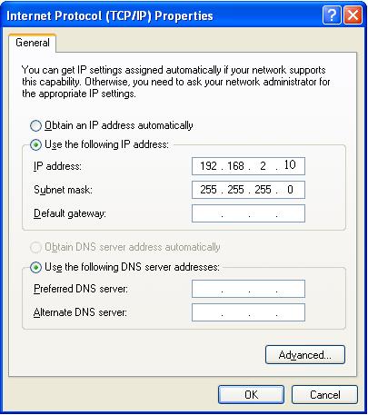
64 64

65 V-1-2. Windows Vista 1. Click the Start button (it should be located in the lower-left corner of your computer), then click Control Panel. Click View Network Status and Tasks, then click Manage Network Connections. Right-click Local Area Network, then select Properties. The Local Area Connection Properties window will then appear, select Internet Protocol Version 4 (TCP / IPv4), and then click Properties. 2. Select Use the following IP address, then input the following values: IP address: Subnet Mask: Click OK when finished. 65
66 66


67 V-1-3. Windows 7 1. Click the Start button (it should be located in the lower-left corner of your computer), then click Control Panel. 2. Under Network and Internet click View network status and tasks. 3. Click Local Area Connection. 67

68 4. Click Properties. 68

69 5. Select Internet Protocol Version 4 (TCP/IPv4) and then click Properties. 6. Select Use the following IP address, then input the following values: IP address: Subnet Mask: Click OK when finished. 69
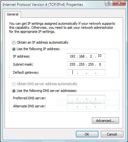
70 70

71 V-1-4. Windows 8 1. From the Windows 8 Start screen, you need to switch to desktop mode. Move your curser to the bottom left of the screen and click. 2. In desktop mode, click the File Explorer icon in the bottom left of the screen, as shown below. 71

72 3. Right click Network and then select Properties. 4. In the window that opens, select Change adapter settings from the left 72


73 side. 5. Choose your connection and right click, then select Properties. 73

74 6. Select Internet Protocol Version 4 (TCP/IPv4) and then click Properties. 7. Select Use the following IP address, then input the following values: IP address: Subnet Mask: Click OK when finished. 74


75 V-1-5. Mac 1. Have your Macintosh computer operate as usual, and click on System Preferences 2. In System Preferences, click on Network. 3. Click on Ethernet in the left panel. 4. Open the drop-down menu labeled Configure IPv4 and select Manually. 75


76 5. Enter the IP address and subnet mask Click on Apply to save the changes. 76
77 V-1-6. Glossary Default Gateway (Access point): Every non-access point IP device needs to configure a default gateway s IP address. When the device sends out an IP packet, if the destination is not on the same network, the device has to send the packet to its default gateway, which will then send it out towards the destination. DHCP: Dynamic Host Configuration Protocol. This protocol automatically gives every computer on your home network an IP address. DNS Server IP Address: DNS stands for Domain Name System, which allows Internet servers to have a domain name (such as point.com) and one or more IP addresses (such as ). A DNS server keeps a database of Internet servers and their respective domain names and IP addresses, so that when a domain name is requested (as in typing "Broadbandaccess point.com" into your Internet browser), the user is sent to the proper IP address. The DNS server IP address used by the computers on your home network is the location of the DNS server your ISP has assigned to you. DSL Modem: DSL stands for Digital Subscriber Line. A DSL modem uses your existing phone lines to transmit data at high speeds. Ethernet: A standard for computer networks. Ethernet networks are connected by special cables and hubs, and move data around at up to 10/100 million bits per second (Mbps). IP Address and Network (Subnet) Mask: IP stands for Internet Protocol. An IP address consists of a series of four numbers separated by periods, that identifies a single, unique Internet computer host in an IP network. Example: It consists of 2 portions: the IP network address, and the host identifier. The IP address is a 32-bit binary pattern, which can be represented as four cascaded decimal numbers separated by. : aaa.aaa.aaa.aaa, where each aaa can be anything from 000 to 255, or as four cascaded binary numbers separated by. : bbbbbbbb.bbbbbbbb.bbbbbbbb.bbbbbbbb, where each b can either be 0 or 1. 77
78 A network mask is also a 32-bit binary pattern, and consists of consecutive leading 1 s followed by consecutive trailing 0 s, such as Therefore sometimes a network mask can also be described simply as x number of leading 1 s. When both are represented side by side in their binary forms, all bits in the IP address that correspond to 1 s in the network mask become part of the IP network address, and the remaining bits correspond to the host ID. For example, if the IP address for a device is, in its binary form, , and if its network mask is, It means the device s network address is , and its host ID is, This is a convenient and efficient method for access points to route IP packets to their destination. ISP Gateway Address: (see ISP for definition). The ISP Gateway Address is an IP address for the Internet access point located at the ISP's office. ISP: Internet Service Provider. An ISP is a business that provides connectivity to the Internet for individuals and other businesses or organizations. LAN: Local Area Network. A LAN is a group of computers and devices connected together in a relatively small area (such as a house or an office). Your home network is considered a LAN. MAC Address: MAC stands for Media Access Control. A MAC address is the hardware address of a device connected to a network. The MAC address is a unique identifier for a device with an Ethernet interface. It is comprised of two parts: 3 bytes of data that corresponds to the Manufacturer ID (unique for each manufacturer), plus 3 bytes that are often used as the product s serial number. NAT: Network Address Translation. This process allows all of the computers on your home network to use one IP address. Using the broadband access point s NAT capability, you can access the Internet from any computer on your home network without having to purchase more IP addresses from your ISP. Port: Network Clients (LAN PC) uses port numbers to distinguish one network application/protocol over another. Below is a list of common applications and protocol/port numbers: 78
79 Application Protocol Port Number Telnet TCP 23 FTP TCP 21 SMTP TCP 25 POP3 TCP 110 H.323 TCP 1720 SNMP UCP 161 SNMP Trap UDP 162 HTTP TCP 80 PPTP TCP 1723 PC Anywhere TCP 5631 PC Anywhere UDP 5632 Access point: A access point is an intelligent network device that forwards packets between different networks based on network layer address information such as IP addresses. Subnet Mask: A subnet mask, which may be a part of the TCP/IP information provided by your ISP, is a set of four numbers (e.g ) configured like an IP address. It is used to create IP address numbers used only within a particular network (as opposed to valid IP address numbers recognized by the Internet, which must be assigned by InterNIC). TCP/IP, UDP: Transmission Control Protocol/Internet Protocol (TCP/IP) and Unreliable Datagram Protocol (UDP). TCP/IP is the standard protocol for data transmission over the Internet. Both TCP and UDP are transport layer protocol. TCP performs proper error detection and error recovery, and thus is reliable. UDP on the other hand is not reliable. They both run on top of the IP (Internet Protocol), a network layer protocol. WAN: Wide Area Network. A network that connects computers located in geographically separate areas (e.g. different buildings, cities, countries). The Internet is a wide area network. Web-based management Graphical User Interface (GUI): Many devices support a graphical user interface that is based on the web browser. This means the user can use the familiar Netscape or Microsoft Internet Explorer to Control/configure or monitor the device being managed. 79
WAP-EN1750R AC1750 Outdoor Mount Access Point. User Manual. Version 1.0, July 5, 2016
 WAP-EN1750R AC1750 Outdoor Mount Access Point User Manual Version 1.0, July 5, 2016 1 FCC Compliance This equipment has been tested and found to comply with the limits for a Class B Digital Device, pursuant
CAP1750. User Manual / v1.1
 CAP1750 User Manual 12-2015 / v1.1 CONTENTS I. Product Information...2 I-1. Package Contents... 2 I-2. System Requirements... 3 I-3. Hardware Overview... 3 I-4. LED Status... 4 I-5. Reset... 4 I-6. Safety
WAP1750 User Manual / v1.0
 WAP1750 User Manual 02 2014 / v1.0 CONTENTS I. Product Information... 4 I 1. Package Contents... 4 I 2. System Requirements... 5 I 3. Hardware Overview... 5 I 4. LED Status... 6 I 5. Reset... 6 I 6. Magnetic
USER MANUAL. WAP-EN Series Wireless Access Points. Version 1.2,0 June 2017
 USER MANUAL WAP-EN Series Wireless Access Points Version 1.2,0 June 2017 FCC Compliance This equipment has been tested and found to comply with the limits for a Class B Digital Device, pursuant to part
WAP1750 User Manual / v1.0
 WAP1750 User Manual 05-2014 / v1.0 CONTENTS I. Product Information... 1 I-1. Package Contents... 1 I-2. System Requirements... 2 I-3. Hardware Overview... 2 I-4. LED Status... 3 I-5. Reset... 3 I-6. Magnetic
IAP1200. User Manual / v1.0
 IAP1200 User Manual 11-2016 / v1.0 CONTENTS I. Product Information...2 I-1. Package Contents... 2 I-2. System Requirements... 3 I-3. Hardware Overview... 3 I-4. LED Status... 4 I-5. Reset... 5 I-6. Safety
OAP1750. User Manual / v1.1
 OAP1750 User Manual 11-2015 / v1.1 CONTENTS I. Product Information... 2 I-1. Package Contents... 2 I-2. System Requirements... 3 I-3. Hardware Overview... 3 I-4. LED Status... 4 I-5. Reset... 4 I-6. Safety
Security SSID Selection: Broadcast SSID:
 69 Security SSID Selection: Broadcast SSID: WMM: Encryption: Select the SSID that the security settings will apply to. If Disabled, then the device will not be broadcasting the SSID. Therefore it will
NMS USER MANUAL. WAP-EN Series Wireless Access Points. Version 1.2, June 2017
 NMS USER MANUAL WAP-EN Series Wireless Access Points Version 1.2, June 2017 Copyright Copyright 2017 Comtrend Corporation. All rights reserved. The information contained herein is proprietary to Comtrend
CAP1300. User Manual / v1.0
 CAP1300 User Manual 09-2017 / v1.0 CONTENTS CONTENTS... 2 OVERVIEW... 8 I Product Information... 9 I-1 Package Contents... 9 I-2 System Requirements... 10 I-3 Hardware Overview... 10 I-4 LED Status...
USER S MANUAL. Wireless-1200AC Managed AP Pro. website
 Wireless-1200AC Managed AP Pro HW12ACM website www.hawkingtech.com e-mail techsupport@hawkingtech.com USER S MANUAL COPYRIGHT 2015 HAWKING TECHNOLOGIES,INC. ALL RIGHTS RESERVED. COPYRIGHT Copyright 2015
USER S MANUAL. Outdoor Wireless-1750AC Managed Access Point Pro. website
 Outdoor Wireless-1750AC Managed Access Point Pro HOW17ACM website www.hawkingtech.com e-mail techsupport@hawkingtech.com USER S MANUAL COPYRIGHT 2017 HAWKING TECHNOLOGIES,INC. ALL RIGHTS RESERVED. COPYRIGHT
EW-7438RPn Mini User Manual
 EW-7438RPn Mini User Manual 04-2015 / v1.1 CONTENTS I. Product Information... 1 I-1. Package Contents... 1 I-2. System Requirements... 1 I-3. LED Status... 1 I-4. Hardware Overview... 3 I-5. Safety Information...
Wireless 11n Smart Repeater AP (1T1R)
") (1T1R) 2014 Table of Contents 1. Introduction...3 1.1 Package contents... 3 1.2 Product Features... 3 1.3 Front Panel Description... 4 1.4 Rear Panel Description... 5 2. Installation...6 2.1 Hardware Installation...
(1T1R) 2014 Table of Contents 1. Introduction...3 1.1 Package contents... 3 1.2 Product Features... 3 1.3 Front Panel Description... 4 1.4 Rear Panel Description... 5 2. Installation...6 2.1 Hardware Installation...
WAP-EN1200C. NMS User Manual. Version 1.0.1, August 2016
 WAP-EN1200C NMS User Manual Version 1.0.1, August 2016 FCC Compliance This equipment has been tested and found to comply with the limits for a Class B Digital Device, pursuant to part 15 of the FCC Rules.
Light Mesh AP. User s Guide. 2009/2/20 v1.0 draft
 Light Mesh AP User s Guide 2009/2/20 v1.0 draft i FCC Certifications This equipment has been tested and found to comply with the limits for a Class B digital device, pursuant to Part 15 of the FCC Rules.
802.11a g Dual Band Wireless Access Point. User s Manual
 802.11a+802.11g Dual Band Wireless Access Point User s Manual 0 Chapter 1 Introduction 1.1 Feature Fully interoperable with IEEE 802.11b compliant products. High-Speed data transfer rate up to 11Mbps.
EW-7478AC User Manual
 EW-7478AC User Manual 03-2016 / v1.0 CONTENTS I. Product Information...1 I-1. Package Contents... 1 I-2. System Requirements... 1 I-3. LED Status... 2 I-4. Switch... 3 I-5. WPS Setup... 5 I-6. WPS Button
EnGenius EAP N Multi-Function AP/Repeater
 EnGenius EAP9550 11N Multi-Function AP/Repeater Table of Content 1. Introduction...4 1.1. Features and Benefits...4 1.2. Package Contents...5 1.3. System Requirement...5 2. Understanding the Hardware...6
Quick Installation Guide
 Quick Installation Guide WAP-EN1750C AC1750 Ceiling Mount Access Point I. I Product Information I-1. Package Contents 1 2 5 6 3 4 7 1. Access Point 5. Quick Installation Guide 2. Ceiling Mount Bracket
Figure 35: Active Directory Screen 6. Select the Group Policy tab, choose Default Domain Policy then click Edit.
 PC and Server Configuration Figure 35: Active Directory Screen 6. Select the Group Policy tab, choose Default Domain Policy then click Edit. Figure 36: Group Policy Tab 7. Select Computer Configuration
AC1200M/MS. User Manual
 AC1200M/MS User Manual Table of Contents User Manual... 1 1 Preface... 1 2 LED Indicators and Connectors... 1 2.1 LED Indicators... 1 2.2 Hardware Installation... 2 3 Voice Prompt (AC1200MS)... 2 4 User
LevelOne User Manual WNC-0600USB N_One Wireless USB Adapter
 LevelOne User Manual WNC-0600USB N_One Wireless USB Adapter V2.0.0-0712 i Safety FCC WARNING This equipment has been tested and found to comply with the limits for a Class B digital device, pursuant to
CV-7428nS User Manual
 CV-7428nS User Manual 09-2012 / v1.0 1 COPYRIGHT Copyright Edimax Technology Co., Ltd. all rights reserved. No part of this publication may be reproduced, transmitted, transcribed, stored in a retrieval
WL-5420AP. User s Guide
 WL-5420AP User s Guide Table of contents INTRODUCTION... 1 About the Operation Modes...2 LED Indicators...5 Solid...5 Ports on the Rear Panel...7 GETTING CONNECTED... 8 WPA AP -CONFIGURATION VIA WEB...
AC750 Wireless Dual-Band Router CR2. User Manual
 AC750 Wireless Dual-Band Router CR2 User Manual Version 1.0 4/25/2014 Table of Content Chapter 1 Introduction... 3 1.1 Features... 3 1.2 System Requirement... 3 1.3 Package Contents... 4 Chapter 2 Hardware
150Mbps WLAN Access Point
 User s Manual 150Mbps WLAN Access Point Model No.: SP918NL http://www.micronet.info Contents Chapter 1 Introduction 1-1 Product Introduction...1 1-2 Safety Information...1 1-3 System Requirements...3 1-4
802.11b/g Access Point WL-8000AP
 802.11b/g Access Point WL-8000AP User s Guide - FCC Certifications This equipment has been tested and found to comply with the limits for a Class B digital device, pursuant to Part 15 of the FCC Rules.
WRT300N-DD User Manual
 WRT300N-DD User Manual Contents Features... 3 Configuring the Router... 3 1 Operation Mode... 8 2 Internet Settings... 8 2.1 WAN... 9 2.2 LAN... 13 2.3 DHCP clients... 15 2.4 Advanced Routing... 15 2.5
Quick Installation Guide
 Quick Installation Guide WAP-PC1200C AC1200 Ceiling Mount Access Point Version AV2.1c June 22, 2017 I I. Product Information I-1. Package Contents 1 2 3 4 5 1. Access Point 2. Ceiling Mount Bracket 3.
RANGER SERIES. 150Mbps Wireless Green Broadband Router DG-BR4000NG. 150 Mbps V
 RANGER SERIES 150Mbps Wireless Green Broadband Router DG-BR4000NG N 150 Mbps V1.2 2011-12-15 FCC warning: This equipment has been tested and found to comply with the limits for a class B digital device,
Wireless-N PCI Adapter User Manual
 Wireless-N PCI Adapter User Manual V1.0 2010-06-28 FCC Certifications Federal Communication Commission Interference Statement This equipment has been tested and found to comply with the limits for a Class
WRE2206. User s Guide. Quick Start Guide. Wireless N300 Range Extender. Default Details. Version 1.00 Edition 1, 01/2015
 WRE2206 Wireless N300 Range Extender Version 1.00 Edition 1, 01/2015 Quick Start Guide User s Guide Default Details Web Address http://zyxelsetup OR http://192.168.1.2 www.zyxel.com User Name admin Password
WAP3205 v2. User s Guide. Quick Start Guide. Wireless N300 Access Point. Default Login Details. Version 1.00 Edition 2, 12/2012
 WAP3205 v2 Wireless N300 Access Point Version 1.00 Edition 2, 12/2012 Quick Start Guide User s Guide Default Login Details LAN IP Address http://192.168.1.2 Password 1234 www.zyxel.com Copyright 2012 ZyXEL
b/g/n 1T1R Wireless USB Adapter. User s Manual
 802.11 b/g/n 1T1R Wireless USB Adapter User s Manual Federal Communication Commission Interference Statement This equipment has been tested and found to comply with the limits for a Class B digital device,
1. Package contents. 2. Connecting ADSL modem and wireless router
 1. Package contents WL-500W wireless router x 1 Power adapter x 1 Utility CD x 1 RJ45 cable x 1 Quick Start Guide x 1 2. Connecting ADSL modem and wireless router 1) Cable connection Wall power outlet
User Manual Gemtek WiMAX Modem
 User Manual Gemtek WiMAX Modem WIXS-177 CONTENTS Chapter 1 Overview...1-1 1.1. Indoor CPE... 1-1 1.2. Outdoor CPE... 1-2 Chapter 2 WEB-GUI...2-3 2.1. System Configuration Login... 2-3 2.2. System Logout...
Wireless b/g Portable Router. User s Guide
 Wireless 802.11b/g Portable Router User s Guide FCC Certifications This equipment has been tested and found to comply with the limits for a Class B digital device, pursuant to Part 15 of the FCC Rules.
XG-520 Wireless b/g Portable Router. User s Manual
 XG-520 Wireless 802.11b/g Portable Router User s Manual FCC Certifications This equipment has been tested and found to comply with the limits for a Class B digital device, pursuant to Part 15 of the FCC
AIRNET 54Mb b/g High Power USB Adapter. User s Manual
 AIRNET 54Mb 802.11b/g High Power USB Adapter User s Manual FCC Certifications Federal Communication Commission Interference Statement This equipment has been tested and found to comply with the limits
WISNETWORKS. WisOS 11ac V /3/21. Software version WisOS 11ac
 WISNETWORKS User Manual V1.1 2016/3/21 Software version 1.0.0021 Table of contents 1. Setup& WMI... 3 1.1 Hardware Setup... 3 1.2 Web Management Interface... 3 2. Status... 4 2.1 Overview... 4 2.1.1 System...
APC-100. IEEE g Wireless USB Adapter. User s Guide v1.0
 APC-100 IEEE 802.11g Wireless USB Adapter User s Guide v1.0 FCC Certifications Federal Communication Commission Interference Statement This equipment has been tested and found to comply with the limits
Wireless-G Router User s Guide
 Wireless-G Router User s Guide 1 Table of Contents Chapter 1: Introduction Installing Your Router System Requirements Installation Instructions Chapter 2: Preparing Your Network Preparing Your Network
802.11n Wireless Access Point. ver.1.0
 802.11n Wireless Access Point User Manual ver.1.0 WLn-501 COPYRIGHT Copyright 2005/2006 by this company. All rights reserved. No part of this publication may be reproduced, transmitted, transcribed, stored
WiFi-Repeater User Manual. Quick Installation Guide(Q.I.G.) REV.1.2
 REV.1.2") WiFi-Repeater User Manual Quick Installation Guide(Q.I.G.) REV.1.2 Introduction: The WiFi Repeater is a combined wired/wireless network connection device designed specifically for small business, office,
WiFi-Repeater User Manual Quick Installation Guide(Q.I.G.) REV.1.2 Introduction: The WiFi Repeater is a combined wired/wireless network connection device designed specifically for small business, office,
EAP N Multi-Function AP/Repeater
 EAP9550 11N Multi-Function AP/Repeater Table of Content 1. Introduction...3 1.1. Features and Benefits...3 1.2. Package Contents...4 1.3. System Requirement...4 2. Modes...5 2.1. Access Point...5 2.2.
802.11N Wireless Broadband Router
 802.11N Wireless Broadband Router Pre-N Wireless Access Point Broadband Internet Access WPS 4-Port Switching Hub User's Guide Table of Contents CHAPTER 1 INTRODUCTION... 1 Wireless Router Features... 1
Wireless LAN Access Point
 Wireless LAN Access Point IEEE 802.11b/g 54Mbps 501903 User s Manual Table of Contents Chapter 1 Introduction... 1 1.1 Package Contents... 2 1.2 Features... 2 1.3 Specifications... 2 1.4 Physical Description...
Quick Installation Guide
 Quick Installation Guide WAP-PC1750W AC1750 Wall Mount Access Point Version A2.1c, June 22, 2017 I Product Information I-1. Package Contents 1 2 3 4 5 6 7 1. WAP-PC1750W Access Point 2. Antennas x 3 3.
WUG2690 User s Manual
 802.11b+g Wireless LAN USB Adapter WUG2690 User s Manual Federal Communication Commission Interference Statement This equipment has been tested and found to comply with the limits for a Class B digital
WH-9200AP a/b/g Dual Radio Wireless Base Station. User s Manual
 WH-9200AP 802.11a/b/g Dual Radio Wireless Base Station User s Manual Regulatory Information Federal Communication Commission Interference Statement This equipment has been tested and found to comply with
IEEE g Wireless PC Card. User s Guide
 IEEE 802.11g Wireless PC Card User s Guide FCC Certifications Federal Communication Commission Interference Statement This equipment has been tested and found to comply with the limits for a Class B digital
LevelOne. User Manual. WAP Mbps PoE Wireless AP V3.0.0
 LevelOne WAP-0005 108Mbps PoE Wireless AP User Manual V3.0.0 i TABLE OF CONTENTS CHAPTER 1 INTRODUCTION... 1 FIGURE 1: WIRELESS ACCESS POINT... 1 FEATURES OF YOUR WIRELESS ACCESS POINT... 1 Security Features...
D-Link AirPlus G DWL-G700AP
 TM D-Link AirPlus G DWL-G700AP 2.4GHz Wireless Access Point Manual Building Networks for People Contents Package Contents...3 Introduction...4 Wireless Basics...6 Getting Started...8 Using the Configuration
Outdoor High Power Wireless N Access Point
 Outdoor High Power Wireless N Access Point Model WND930 User Manual December 2017 202-11483-02 350 East Plumeria Drive San Jose, CA 95134 USA Support Thank you for purchasing this NETGEAR product. You
The VWRT510&WRT500 High Speed Router User s Guide
 The VWRT510&WRT500 High Speed Router User s Guide The page 1 of 53 Table of Contents 1 Preface... 4 2 LED Indicators and Connectors... 5 2.1 LED Indicators... 6 2.2 Hardware Installation... 7 3 Voice Prompt...
Outdoor Wireless USB Adapter User Guide
 Outdoor Wireless USB Adapter User Guide FCC STATEMENT This equipment has been tested and found to comply with the limits for a Class B digital device, pursuant to part 15 of the FCC Rules. These limits
MIMO Wireless Broadband Route r User s Manual 1
 MIMO Wireless Broadband Router User s Manual 1 Introduction...4 Features...4 Minimum Requirements...4 Package Content...4 Note...4 Get to know the Broadband Router...5 Back Panel...5 Front Panel...6 Setup
Section 3 - Configuration. Enable Auto Channel Scan:
 Enable Auto Channel Scan: Wireless Channel: The Auto Channel Scan setting can be selected to allow the DGL-4500 to choose the channel with the least amount of interference. Indicates the channel setting
Wireless USB Port Multi-Functional Printer Server. Model # AMPS240W. User s Manual. Ver. 1A
 Wireless USB 2.0 1-Port Multi-Functional Printer Server Model # AMPS240W User s Manual Ver. 1A Table of Contents 1 Introduction...3 1.1 Package Contents... 3 1.2 System Requirements... 3 2 Multi-Functional
Nexxt Solutions - NexxtGate150 Access Point. Quick Installation Guide
 Quick Installation Guide 1. Introduction Thank you for purchasing the Nexxt Solutions 2.4 GHz High-Power Wireless-N Access Point NexxtGate150. If any of the following items are mismatched, missing or damaged,
High Power Wireless N USB Adapter User s Manual
 High Power Wireless N USB Adapter User s Manual 2 Table of Contents 1. Introduction... 4 1.1 Package Contents... 4 1.2 Features... 4 2. Installation... 5 3. Configuring the Adapter... 11 4. Wireless Utility...
Wireless Long Range Access Point / Client Bridge EOC5510. User Manual V1.0
 Wireless Long Range Access Point / Client Bridge EOC5510 User Manual V1.0 0 Table of Contents 1 PRODUCT OVERVIEW... 3 1.1 FEATURE... 3 1.2 BENEFITS... 5 1.3 PACKAGE CONTENTS... 6 1.4 SYSTEM REQUIREMENT...
Wireless LAN Access Point
 Wireless LAN Access Point IEEE 802.11b/g 54Mbps User s Manual Table of Contents Chapter 1 Introduction... 1 1.1 Package Contents... 2 1.2 Features... 2 1.3 Specifications... 2 1.4 Physical Description...
COPYRIGHT. Linux Open Source Code Certain Edimax products include software codes developed by third parties, which are
 COPYRIGHT Copyright Edimax Technology Co., Ltd. all rights reserved. No part of this publication may be reproduced, transmitted, transcribed, stored in a retrieval system, or translated into any language
Introduction... 3 Features... 3 Minimum Requirements... 3 Package Content... 3 Note... 3 Get to know the Broadband Router... 4 Back Panel...
 Introduction... 3 Features... 3 Minimum Requirements... 3 Package Content... 3 Note... 3 Get to know the Broadband Router... 4 Back Panel... 4 Front Panel... 5 Setup Diagram... 6 Getting started... 7 Chapter
802.11a/b/g Access Point. User s Guide
 802.11a/b/g Access Point User s Guide FCC Certifications This equipment has been tested and found to comply with the limits for a Class B digital device, pursuant to Part 15 of the FCC Rules. These limits
Wireless Broadband Router
 LW6005A-R2 Wireless Broadband Router Manual 1 Introduction... 4 Features... 4 Minimum Requirements... 4 Package Content... 4 Note... 4 Get to know the Broadband Router... 5 Back Panel... 5 Front Panel...
Wireless LAN Access Point
 Wireless LAN Access Point IEEE 802.11b 11Mbps User s Manual Table of Contents Chapter 1 Introduction... 1 1.1 Package Contents... 2 1.2 Features... 2 1.3 Specifications... 2 1.4 Physical Description...
Front Matter. Edge Wireless System (EWS150) Edge Wireless System. Configuration Guide. Introducing the EWS150 Configuration Updating the Firmware
 Edge Wireless System. Configuration Guide. Introducing the EWS150 Configuration Updating the Firmware") Edge Wireless System Front Matter Configuration Guide Edge Wireless System (EWS150) Introducing the EWS150 Configuration Updating the Firmware June 10th, 2007 210-0028-01 Rev. D Copyright 2003 2007 Strix
Edge Wireless System Front Matter Configuration Guide Edge Wireless System (EWS150) Introducing the EWS150 Configuration Updating the Firmware June 10th, 2007 210-0028-01 Rev. D Copyright 2003 2007 Strix
LP-2396K Outdoor 2.4GHz Wireless AP/CPE/Bridge
 User Manual LP-2396K Outdoor 2.4GHz Wireless AP/CPE/Bridge 1 Table of Contents 1. Introduction... 3 1.1 Product Introduction... 4 1.2 Package Content... 5 1.3 Product Features... 6 1.4 Application... 6
WAP6405. User s Guide. Quick Start Guide. 5GHz AC1750 Gigabit Wireless Bridge. Default Login Details. Version 1.00 Edition 1, 06/2016
 WAP6405 5GHz AC1750 Gigabit Wireless Bridge Version 1.00 Edition 1, 06/2016 Quick Start Guide User s Guide Default Login Details LAN IP Address http://192.168.1.2 (AP Mode) http://192.168.1.5 (Repeater
WRE6505 v2. User s Guide. Quick Start Guide. Wireless AC750 Range Extender. Default Login Details. Version 1.00 Edition 1, 10/2016
 WRE6505 v2 Wireless AC750 Range Extender Version 1.00 Edition 1, 10/2016 Quick Start Guide User s Guide Default Login Details Web Address http://zyxelsetup http://dhcp-assigned IP www.zyxel.comhttp://192.168.1.2
WHR-300HP2 / WHR-600D User Manual
 AirStation WHR-300HP2 / WHR-600D User Manual www.buffalotech.com 35020160-03 2015.04 Contents Chapter 1 - Product Overview...6 Package Contents...6 Diagrams and Layout...6 Front Panel...6 Back Panel...8
IP806GA/GB Wireless ADSL Router
 IP806GA/GB Wireless ADSL Router 802.11g/802.11b Wireless Access Point ADSL Modem NAT Router 4-Port Switching Hub User's Guide DECLARATION OF CON FORMITY This device complies with Part 15 of the FCC Rules.
CV-7438nDM User Manual
 CV-7438nDM User Manual 11-2013 / v1.1 CONTENTS I. Product Information... 4 I-1. Package Contents... 4 I-2. System Requirements... 4 I-3. LED Status... 4 I-4. Rear Panel... 5 I-5. Safety Information...
WL-5450AP & WL-5460AP Wireless Access Point. User s Guide
 WL-5450AP & WL-5460AP Wireless Access Point User s Guide 1 FCC Certifications This equipment has been tested and found to comply with the limits for a Class B digital device, pursuant to Part 15 of the
Wireless Access Point
 802.11g / 802.11b / WPA Wireless Access Point User Guide TABLE OF CONTENTS CHAPTER 1 INTRODUCTION... 1 Features of your Wireless Access Point... 1 Package Contents... 4 Physical Details... 4 CHAPTER 2
CE APPROVED.4 INTRODUCTION.5 PACKAGE CONTENTS. 6 PRE - INSTALLATION CHECKLIST. 6 SYSTEM REQUIREMENTS. 6 FEATURES AND BENEFITS.11 SETUP WIZARD.
 Web Edition Dec. 2002 Contents CE APPROVED...4 INTRODUCTION...5 PACKAGE CONTENTS... 6 PRE - INSTALLATION CHECKLIST... 6 SYSTEM REQUIREMENTS... 6 FEATURES AND BENEFITS... 7 4 - PORT CABLE/XDSL ROUTER...9
WRE6606. User s Guide. Quick Start Guide. Dual-Band Wireless AC1300 Access Point. Default Login Details. Version 1.00 (ABDU.0) Edition 1, 10/2016
 Edition 1, 10/2016") WRE6606 Dual-Band Wireless AC1300 Access Point Version 1.00 (ABDU.0) Edition 1, 10/2016 Quick Start Guide User s Guide Default Login Details Web Address http://zyxelsetup http://dhcp-assigned IP www.zyxel.comhttp://192.168.1.2
WRE6606 Dual-Band Wireless AC1300 Access Point Version 1.00 (ABDU.0) Edition 1, 10/2016 Quick Start Guide User s Guide Default Login Details Web Address http://zyxelsetup http://dhcp-assigned IP www.zyxel.comhttp://192.168.1.2
Dual Radio Concurrent AP/CB EOA7535 User Manual Version : 1.0
 Dual Radio Concurrent AP/CB EOA7535 User Manual Version : 1.0 Table of Contents 1 PRODUCT OVERVIEW... 3 1.1 BENEFITS... 3 1.2 FEATURE... 5 1.3 PACKAGE CONTENTS... 6 1.4 SYSTEM REQUIREMENT... 6 1.5 HARDWARE
1. Press "Speed Test" to find out your actual uplink and downlink speed.
 ASRock G10 Gaming Router 6.4 QoS Settings QoS Add Gaming Boost web page. Gaming Boost: Enable or disable the Gaming Boost. Bandwidth The router supports Gaming Boost natively, which identifies and intelligently
11g Wireless Broadband Router
 LevelOne WBR-3408 User Manual 11g Wireless Broadband Router (Roteador banda-larga sem fio- Wireless G) Ver. 3.000 Safety FCC WARNING This equipment may generate or use radio frequency energy. Changes or
TEW-211BRP. Wireless AP Router. User s Manual
 TEW-211BRP Wireless AP Router User s Manual Version 1.4 - Jan 2002 CONTENTS Introduction...3 Hardware Installation...5 General Wireless AP Router System Connection...6 Wireless AP Router Default Settings
User Guide. For TP-Link Auranet Access Points
 User Guide For TP-Link Auranet Access Points EAP110 / EAP115 / EAP225 / EAP245 / EAP320 / EAP330 / EAP115-Wall / EAP110-Outdoor 1910012276 REV 2.0.2 October 2017 CONTENTS About this User Guide... 1 Overview...
AplombTech Smart Router Manual
 AplombTech Smart Router Manual (Version: 1.0) 1 Version & Purpose Version Manual version V 1.0 Explanation Corresponds to the initial version of device Purpose This manual describes the function features
3G-6408n User Manual
 3G-6408n User Manual 05-2012 / v1.0 COPYRIGHT Copyright Edimax Technology Co., Ltd. all rights reserved. No part of this publication may be reproduced, transmitted, transcribed, stored in a retrieval system,
54M Wireless LAN CardBus Card
 54M Wireless LAN CardBus Card User s Manual Ver.2.0 Federal Communication Commission Interference Statement This equipment has been tested and found to comply with the limits for a Class B digital device,
High Output Power b/g/n Multi-function Access Point EAP N Multi-Function Access Point V1.0
 1 High Output Power 802.11 b/g/n Multi-function Access Point EAP150 802.11 N Multi-Function Access Point V1.0 1 Table of Contents 1 Introduction... 4 1.1 Features and Benefits... 4 1.2 Package Contents...
802.11a/b/g Outdoor Dual Radio Concurrent AP/Bridge/Repeater EOA7530 User Manual Version : 1.1
 802.11a/b/g Outdoor Dual Radio Concurrent AP/Bridge/Repeater EOA7530 User Manual Version : 1.1 Table of Contents CHAPTER 1 PRODUCT OVERVIEW...4 1.1 FEATURES... 4 1.2 BENEFITS... 5 1.3 PACKAGE CONTENTS...
Wireless-N Pocket AP/Router ETR9360. Wireless N Pocket AP/Router V1.0
 Wireless-N Pocket AP/Router ETR9360 Wireless N Pocket AP/Router V1.0 1 1. Package Contents...5 2. System Requirements...5 3. Introduction...6 4. Features...7 5. Hardware Overview...8 6. Before you Begin...10
Chapter 1 Introduction
 Copyright Statement is the registered trademark of Zonet Technology Inc. All the products and product names mentioned herein are the trademarks or registered trademarks of their respective holders. Copyright
Introduction... 3 Features... 3 Minimum Requirements... 3 Package Content... 3 Note... 3 Get to know the Broadband Router... 4 Back Panel...
 Introduction... 3 Features... 3 Minimum Requirements... 3 Package Content... 3 Note... 3 Get to know the Broadband Router... 4 Back Panel... 4 Front Panel... 5 Setup Diagram... 6 Getting started... 7 Chapter
Grandstream Networks, Inc. GWN76xx Wi-Fi Access Points Master/Slave Architecture Guide
 Grandstream Networks, Inc. GWN76xx Wi-Fi Access Points Master/Slave Architecture Guide Table of Contents INTRODUCTION... 4 DISCOVER AND PAIR GWN76XX ACCESS POINTS... 5 Discover GWN76xx... 5 Method 1: Discover
Table of Contents. Chapter 1 Product Overview Features Package Contents LED Indicator and Panel Description...
 Copyright Statement is the registered trademark of Monoprice. All the products and product names mentioned herein are the trademarks or registered trademarks of their respective holders. Copyright of the
U S E R M A N U A L b/g PC CARD
 U S E R M A N U A L 802.11b/g PC CARD Table of Content CHAPTER 1 INTRODUCTION... 1 1.1 WIRELESS LAN FEATURE FUNCTIONS... 1 1.2 REGULATORY NOTICE... 1 1.2.1 FCC Class B Statement...1 1.2.2 Canadian Regulatory
XAVi Technologies Corporation Tel: Fax: F, No. 129, Hsing Te Road, Sanchung City, Taipei County 241, Taiwan
 XAVi Technologies Corporation Tel: +886-2-2995-7953 Fax: +886-2-29957954 9F, No. 129, Hsing Te Road, Sanchung City, Taipei County 241, Taiwan Copyright 2005, XAVi Technologies Corporation Information in
WLA-5000AP Access Point Mode
 WLA-5000AP Access Point Mode User s Guide Copyright Statement No part of this publication may be reproduced, stored in a retrieval system, or transmitted in any form or by any means, whether electronic,
Wireless Outdoor. Client Bridge / Access Point
 Wireless Outdoor Client Bridge / Access Point 2012 User Manual Version : 1.0 1 Product Overview Thank you for using ANSEL 2012. It is a powerful, enhanced, enterprise scale product with 4+1 multi-functions
USB Wireless Network Adapter User s Manual
 USB Wireless Network Adapter User s Manual Rev 0.9 Regulatory compliance FCC Warning This equipment has been tested and found to comply with the limits for a Class B digital device, pursuant to part 15