Table of Contents HOL NET
|
|
|
- Griselda Underwood
- 5 years ago
- Views:
Transcription
1 Table of Contents Lab Overview - - VMware NSX Multi-Site and SRM in an Active- Standby Setup... 2 Lab Guidance... 3 Lab Introduction... 9 Module 1 - Review Pre-Configured Multi-Site NSX and Configure Site-Local Routing (45 Minutes) Module Guidance Topology Overview Review vcenter Configurations Review NSX Manager Configurations Review Universal Controller Cluster Review Universal Logical Network Preparation Review the Logical Switches in the Environment Review NSX Edge Configurations Configure BGP Filter on RegionB0_Perimeter_GW Enable BGP on Universal Logical Router RegionA Enable BGP on Universal Logical Router RegionB Verify Application Connectivity Create Universal Distributed Firewall Rules Leveraging Universal Security Tags Module 1 Conclusion Module 2 - Site Recovery Manager Configuration & Execution (45 Minutes) Module Guidance Creation of SRM protection groups for Application Configure Network Mappings Configure Folder Mappings Configure Resource Mappings Configure Placeholder Datastore Create Replications Create Protection Group Create Recovery Plan Bring Down the Edge GW in RegionA Deploy OneArm-LB in RegionB Run the Recovery Plan to Failover the site Configure BGP Filter on RegionB0_Perimeter_GW Connect to 3-Tier App Module 2 Conclusion Page 1
2 Lab Overview - - VMware NSX Multi-Site and SRM in an Active- Standby Setup Page 2
3 Lab Guidance Note: It may take more than 90 minutes to complete this lab. You are not expected to finish all the modules during your time. The modules are independent of each other so you can start at the beginning of any module and proceed from there. You can use the Table of Contents to access any module of your choosing. The Table of Contents can be accessed in the upper right-hand corner of the Lab Manual. In this lab, students will leverage on Cross VC-NSX and failover a 3-tier application from Primary Site to Protected Site with minimal changes to the environment. Students will learn to resolve some of the difficult challenges faced by traditional disaster recovery solutions such as the need to change networks (IP addresses) and synchronization of security policies. Lab Module List: Module 1 - Review Pre-Configured Multi-Site NSX and Configure Site-Local Routing (45 minutes) (Advanced) In this module, students will review the two different logical topologies which describes the current state and state after the full failover of the application traffic. This module will walk the students through configuring site specific local routing in a multi-site environment, influence egress traffic utilizing Locale ID, influence ingress routing using route filters as well as configuring universal distributed firewall rules by using dynamic criteria and universal security tags. Module 2 - Site Recovery Manager Configuration & Execution (45 minutes) (Advanced) In this module students will configure SRM including protection groups, recovery and protection plans. Subsequently, students will learn full failover of the application. Lab Captains: Module 1 - TAY Wen Bin, Systems Engineer, Singapore Module 2 - TAY Wen Bin, Systems Engineer, Singapore This lab manual can be downloaded from the Hands-on Labs Document site found here: This lab may be available in other languages. To set your language preference and have a localized manual deployed with your lab, you may utilize this document to help guide you through the process: Page 3

4 Location of the Main Console 1. The area in the RED box contains the Main Console. The Lab Manual is on the tab to the Right of the Main Console. 2. A particular lab may have additional consoles found on separate tabs in the upper left. You will be directed to open another specific console if needed. 3. Your lab starts with 90 minutes on the timer. The lab can not be saved. All your work must be done during the lab session. But you can click the EXTEND to increase your time. If you are at a VMware event, you can extend your lab time twice, for up to 30 minutes. Each click gives you an additional 15 minutes. Outside of VMware events, you can extend your lab time up to 9 hours and 30 minutes. Each click gives you an additional hour. Alternate Methods of Keyboard Data Entry During this module, you will input text into the Main Console. Besides directly typing it in, there are two very helpful methods of entering data which make it easier to enter complex data. Page 4
5 Click and Drag Lab Manual Content Into Console Active Window You can also click and drag text and Command Line Interface (CLI) commands directly from the Lab Manual into the active window in the Main Console. Accessing the Online International Keyboard You can also use the Online International Keyboard found in the Main Console. 1. Click on the Keyboard Icon found on the Windows Quick Launch Task Bar. Page 5

6 Click once in active console window In this example, you will use the Online Keyboard to enter the sign used in addresses. The sign is Shift-2 on US keyboard layouts. 1. Click once in the active console window. 2. Click on the Shift key. Click on key 1. Click on the "@ key". Notice sign entered in the active console window. Page 6


7 Activation Prompt or Watermark When you first start your lab, you may notice a watermark on the desktop indicating that Windows is not activated. One of the major benefits of virtualization is that virtual machines can be moved and run on any platform. The Hands-on Labs utilizes this benefit and we are able to run the labs out of multiple datacenters. However, these datacenters may not have identical processors, which triggers a Microsoft activation check through the Internet. Rest assured, VMware and the Hands-on Labs are in full compliance with Microsoft licensing requirements. The lab that you are using is a self-contained pod and does not have full access to the Internet, which is required for Windows to verify the activation. Without full access to the Internet, this automated process fails and you see this watermark. This cosmetic issue has no effect on your lab. Look at the lower right portion of the screen Page 7
8 Please check to see that your lab is finished all the startup routines and is ready for you to start. If you see anything other than "Ready", please wait a few minutes. If after 5 minutes your lab has not changed to "Ready", please ask for assistance. Page 8
9 Lab Introduction IT organizations require a methodology for replicating and recovering workloads from a primary site to a recovery site in an event of a disaster or an un-planned outage. To facilitate and automate this recovery process of workloads VMware has products such as Site Recovery Manager (SRM) and vsphere Replication that can automate and orchestrate the recovery process during a failure from a primary site to a recovery site. Today, SRM recovers replicated virtual machines from a primary to a secondary data center. SRM can perform network mapping (and re-mapping) between the primary and secondary locations so that recovered virtual machines can be re-connected to the appropriate network. These networks can be a VLAN-backed Distributed Virtual Port Group (dvpg) or a NSX Logical Switch. NSX and network virtualization enhance the Disaster Recovery solution by preserving L2 and recovering the entire logical network topology at the recovery site. NSX also adds API based automation at the networking layer to further improve Recovery Point Objective (RPO) and Recovery Time Objective (RTO) goals. Combining NSX with a SRM based DR design dramatically simplifies the recovery of vital networking services in the secondary location including Logical Switches, Distributed Logical Routers and Distributed Firewall (DFW) Rules. This lab will describe the process of recovering workloads backed by NSX virtual networks. NSX supports seamless spanning of network and security policies across multiple sites with Cross-VC NSX. The DR solution can also be built without leveraging Cross-VC NSX by using an external replication/synchronization mechanism (such as vro) to recreate Logical Networks and Security between separate NSX instances across the two sites. However, Cross vcenter NSX greatly simplifies the process. Deployment elements consist of Universal Logical Switches, Universal Distributed Logical Router and Universal Distributed Firewalls. These universal objects facilitate the creation of a single unified logical network (L2, L3, DFW) across protected and recovery sites. The application can failover and recover seamlessly without the need for manually re-creating the network on the recovery site or manually mapping/re-mapping IP addresses. In this lab, we will address the most popular scenario of full failover of the 3-Tier application in case of extended outage or a catastrophic failure. Page 9
10 Module 1 - Review Pre- Configured Multi-Site NSX and Configure Site-Local Routing (45 Minutes) Page 10
11 Module Guidance In this module, students will review the existing multi-site configuration for various components such as NSX Managers, vcenter configuration, controller cluster, host preparation, logical network preparation as well as configuration of Edge Gateways on both sites. Students will also modify the Locale-ID of the Site RegionB01 to influence the egress traffic for all the application traffic. We will also walk you through configuring routing between Universal Distributed Logical Routers and Edge Gateways on both sites using BGP. Page 11

12 Topology Overview This section will familiarize you with the overall lab setup. It describes and explains the environment including the pre-configured logical topology and final logical topology after you are done with both Module 1 and 2. Virtual Environment Topology The picture shows the vsphere hosts and how VMs are placed across the different clusters, the Distributed Virtual Switches (DVS). The VTEP IP addresses associated to the hosts are also displayed. Clusters RegionA01-MGMT01& RegionA01-COMP01 are both managed by vcenter Server A (vcsa-01a.corp.local). Page 12
 configuration in the lab consists of the following: RegionA0_TZ: this TZ has a local scope for vcenter A and is available on both clusters of Region A01.")
13 RegionB01-COMP01 is managed by vcenter Server B (vcsa-01b.corp.local). Both vcenters are connected to a common Platform Services Controller (psc-01a.corp.local) that resides on the management network of Region A01. NSX Transport Zone (TZ) configuration in the lab consists of the following: RegionA0_TZ: this TZ has a local scope for vcenter A and is available on both clusters of Region A01. It is already pre-configured in the lab upon startup. Universal_TZ: this TZ has a universal scope and is available on both vcenters. It is already pre-configured in the lab upon startup. Pre-configured Logical Network Topology The above diagram shows the topology of this lab. There are five NSX Universal Logical Switches in this lab: Web_Tier_ULS, App_Tier_ULS, & DB_Tier_ULS, RegionA01_Transit, & RegionB01_Transit The 3-Tier application (Web, App and DB) is already configured. The One-Arm Load Balancer in RegionA0 is attached to Web_Tier_ULS and helps to load balance traffic between the two Web Servers. An identical One-Arm Load Balancer has also been configured RegionB0 but has not been deployed. The Logical Switches are attached to a Universal Distributed Logical Router (UDLR), which in turn is attached to an NSX Edge Services Gateway (ESG) in each region. BGP routing guarantees route exchange Page 13

14 between the ESGs and the external router. In addition, vsphere Replication is configured to replicate the 3-Tier application VMs. SRM has also been pre-installed and configured with the initial pairing. All this configuration is done in advance to concentrate on the actual use case we intend to highlight. During the course of the lab, you will configure elements shown in red boxes above including ibgp between UDLR and ESGs on both the sites as well as BGP prefix list for filtering routes. Logical Topology after Full Application Failover The above diagram shows the topology of this lab after performing a full application failover. The north-south traffic, east-west traffic and One-Arm Load Balancer will exist only in the Recovery Site after a full application failover. Page 14
15 Review vcenter Configurations In this lab, the two vcenter Servers have been configured in Enhanced Linked Mode. This allows both vcenter Servers to be managed through the same vsphere Web Client session. While in Enhanced Linked Mode, both NSX environments can also be configured in the the same vsphere Web Client session. Login to the vsphere Web Client Open Google Chrome web browser. Login to vsphere Web Client and verify that you can access both vcenter Servers. 1. Enter as user name 2. Enter VMware1! as password 3. Click Login Page 15
16 View Hosts and Clusters 1. Click Home icon 2. Click Hosts and Clusters Verify Both vcenter Servers Are Available Ensure that both vcenter Servers are visible Page 16

17 Review NSX Manager Configurations You will review the roles of assigned to NSX Manager. The NSX manager register in Region A0 will have the Primary role. The NSX manager registered in Region B0 will have the secondary role. Navigate to the Networking & Security tab 1. Click on Home icon 2. Click on Networking & Security Page 17


18 Navigate to the Installation and Upgrade Tab 1. Click on Installation and Upgrade Verify NSX Manager Roles 1. Click on Management 2. Click on NSX Managers In this lab, two NSX Managers have been configured with Primary and Secondary roles. Verify that both NSX Managers are assigned a role. Page 18
19 Review Universal Controller Cluster Now you will review the NSX Universal Controller Cluster. The NSX Universal Controller Cluster performs the required control plane functions across both vcenter Servers and their respective NSX Managers. This enables the configuration of Universal Logical Switches, Universal Logical Routers, and Universal Distributed Firewall Rules. Verify Controllers on Primary and Secondary NSX Managers To reduce the amount of required resources for this lab, we only have one controller instead of three. In production environment, we should have three controllers for high availability. In addition, the one controller will appear twice as it is connected to both the primary and secondary NSX managers. Hence verify that Controller-01 appear twice in the NSX Controller Nodes section and are shown as "Connected". Page 19
20 Review Universal Logical Network Preparation You will now review the pre-configured elements in the Logical Network Preparation tab. Review Universal Segment ID pool on the Primary NSX Manager Before Universal Logical Switches can be configured, a Universal Segment ID pool must be created. The Universal Segment ID pool must be a unique range from all other Segment ID pools in use on both NSX Managers configured in a cross vcenter environment. 1. Select Logical Network Preparation 2. Select Primary NSX Manager Note the different range used for Segment ID pool and Universal Segment ID pool. Page 20

21 Change to the Secondary NSX Manager To change the View to the Secondary NSX Manager: 1. Click on NSX Manager drop down 2. Select Secondary Review Universal Segment ID pool on the Secondary NSX Manager Page 21

22 The Secondary NSX Manager must also be configured with a Segment ID Pool. The Segment ID pools configured on all NSX Managers must not be overlapping. The Universal Segment ID pool is synchronized from the Primary NSX Manager. Note the different range used for Segment ID pool and Universal Segment ID pool. In addition, verify the Segment ID pool on the Secondary NSX Manager does not overlap with the Segment ID pool on the Primary NSX Manager and that the Universal Segment ID pool is synchronized. Review Universal Transport Zones Transport Zones define what clusters can participate in a specific Logical Network. Global Transport Zones are confined to a single vcenter Server. Universal Transport Zones may span vcenter Servers. Verify the clusters connected to the Universal Transit Zone. 1. Select Transport Zones Page 22
23 2. Select Universal_TZ 3. Click Connect Clusters icon 4. Verify the cluster RegionB01-COMP01 is connected and in Normal status 5. Click Cancel Switch to the Primary NSX Manager by changing the in the drop-down from the previous step and review the configuration of the Universal_TZ. Using the same view and steps outlined above. Verify clusters RegionA01-COMP01 and RegionA01-MGMT01 are connected and in Normal status. Page 23

24 Review the Logical Switches in the Environment Next, you will review the pre-configured Universal Logical Switches and create a new ULS. Review Universal Logical Switches on Primary NSX Manager Universal Logical Switches are configured in the same tab as Global Logical Switches. Verify the five pre-configured Universal Logical Switches exist. 1. Select Logical Switches on the left navigator pane 2. Select (Role: Primary) 3. Verify five Logical Switches are configured and defined in the Universal TZ. You can see that the Segment IDs of each Universal Logical Switch falls within the range of the Universal Segment ID pool. Page 24
 Verify the Universal Logical Switches match the configuration on the Primary NSX Manager.")
25 Verify Universal Logical Switches on Secondary NSX Manager Universal Logical Switches including their Segment ID are synchronized across Primary and Secondary NSX Managers. 1. Select (Role: Secondary) Verify the Universal Logical Switches match the configuration on the Primary NSX Manager. The Logical Switches, Transport Zone and Segment IDs are synchronized on all NSX Managers in this environment. Page 25

26 Review NSX Edge Configurations NSX Edges provide connectivity for north-south communication and east-west communication. There are two pre-configured NSX Edges for north-south communication. These perimeter gateways are configured with dynamic routing utilizing BGP. A third NSX Edge has been pre-configured as a Universal Distributed Logical Router (UDLR) providing east-west routing among the application logical switches and connectivity to Transit ULS in each site for north-south communication to the perimeter gateway. There are also identical NSX Edges that are implemented as One-Arm Load Balancers on RegionA0 and RegionB0. These One-Arm Load Balancers help to load balance traffic going to the Web Servers. Local Egress Traffic is routed via the ESG at the site which the traffic originated from. East-west traffic utilizes the UDLR for optimization between VMs. This configuration requires dynamic routing between the physical network and the ESGs as well as between the ESGs and the UDLR. The UDLR advertises the configured network to both ESGs. The ESGs advertises the UDLR networks to both sites' physical network. This configuration allows the physical network to transmit and receive traffic to and from the same network at both sites. 1. Traffic originating from RegionA0 VMs egresses the logical network through the RegionA0 ESG 2. Traffic originating from RegionB0 VMs egresses the logical network through the RegionB0 ESG 3. Traffic between VMs utilizes the UDLR for east-west optimization Page 26
 3.")

27 Review Perimeter Gateway Configurations To view the configuration of the RegionA0_Perimeter_GW 1. Click NSX Edges 2. Select (Role: Primary) 3. Double-click on the RegionA0_Perimeter_GW Review the Interface Configuration To view the interface configuration 1. Select Manage 2. Select Settings 3. Select Interfaces Page 27

28 Review the Interfaces configured vnic0 is configured with an address in the subnet of the RegionA0 uplink network. It is connected to the VLAN backed portgroup ESXi-RegionA01-vDS-MGMT. The type of interface is an uplink typically providing updates to the datacenter's physical routing infrastructure. vnic1 is configured with an address in the subnet of the RegionA0_Transit network. It is connected to the Universal Logical Switch RegionA0_Transit. The type of interface is internal (and in this case) connected downstream to a logical switch shared by the UDLR. Review Routing Global Configuration 1. Select Routing 2. Select Global Configuration. Note that ECMP and BGP are enabled. Page 28
29 Review Routing BGP Configuration 1. Select BGP. Review the configured neighbors. The ESG has two neighbors (upstream router) and (ULDR). Page 29

30 Navigate to Networking & Security 1. Click Home icon 2. Click Networking & Security Switch to the Secondary NSX Manager Note that this is an optional step and you may proceed to the next step if you are not interested to review RegionB0_Perimeter_GW on Secondary NSX Manager. Page 30

31 1. Click NSX Edges 2. Select (Role: Secondary) Like RegionA0_Perimeter_GW on Primary NSX Manager, RegionB0_Perimeter_GW on Secondary NSX Manager is also pre-configured. If you wish to review RegionB0_Perimeter_GW, please perform the same steps earlier that were used to review RegionA0_Perimeter_GW. Once you have reviewed the RegionB0_Perimeter_GW, return to this NSX Edges section again and select the Primary NSX Manager. Review Universal Distributed Logical Router Configuration 1. Ensure (Role: Primary) is selected 2. Double-click Universal_DLR_01 Page 31

32 Review UDLR General Configuration To review the UDLR settings, perform the following: 1. Click Manage 2. Click Settings 3. Click Configuration You may need to scroll down to see that Local Egress is enabled; this can only be enabled during creation of the ULDR. In addition, if you scroll down further, you will see that a logical router appliance has been deployed. Page 32

33 Review UDLR Interface Configuration 1. Select the Interfaces section 2. Review the configured vnics There are two uplink interfaces configured: The RegionA0_Uplink interface is configured on the Primary NSX Manager UDLR The RegionB0_Uplink interface is configured on the Secondary NSX Manager UDLR The internal interfaces are configured on the Primary NSX Manager and the configuration of the UDLR is synchronized with the Secondary NSX Manager. Page 33

34 Navigate to Networking & Security 1. Click Home icon 2. Click Networking & Security Review the One-Arm Load Balancer Configuration 1. Click NSX Edges 2. Double-click RegionA0-OneArm-LB Page 34

35 Navigate to Load Balancer Section 1. Click Load Balancer 2. Click Pools Page 35

36 Check the Status of Pool 1. Click Show Pool Statistics 2. Click pool-1 Make sure the status of pool-1 and it's members is up. Page 36
37 Configure BGP Filter on RegionB0_Perimeter_GW In this section, you will configure a BGP Route Filter on the perimeter gateway in recovery site (RegionB0) to deny route advertisements for Web, App and DB networks out of Recovery Site RegionB0. Navigate to Networking & Security 1. Click Home icon 2. Click Networking & Security Page 37


38 Access the RegionB0_Perimeter_GW 1. Click NSX Edges 2. Select (Role: Secondary) 3. Double-click the RegionB0_Perimeter_GW Navigate to Routing Option 1. Click Manage 2. Click Routing Page 38
39 3. Click BGP 4. Select the neighbor Click Pencil icon Add the BGP Filters for the neighbor 1. Click Green Plus icon Page 39

40 Create Deny Filters Create BGP Filters to deny /24, /24 and /24 1. Select Out for Direction 2. Select Deny for Action 3. Enter /24 for Network 4. Click OK Repeat steps 1-4 for /24 and /24 networks Create Permit Filter Page 40

41 Create BGP Filter to permit /24 1. Select Out for Direction 2. Select Permit for Action 3. Enter /24 for Network 4. Click OK Finish creating filters 1. Verify your filters match above 2. Click OK Page 41

42 Publish Changes 1. Click Publish Changes The BGP filter created on Edge GW will block the publishing of /24, /24 and /24 subnets to the external router. Page 42
43 Enable BGP on Universal Logical Router RegionA0 You will now configure BGP on the Universal Logical Distributed Router. Navigate to Networking & Security 1. Click Home icon 2. Click Networking & Security Page 43


44 Navigate to the UDLR 1. Click NSX Edges 2. Click NSX Manager drop down list 3. Select (Role: Primary) 4. Double-click Universal_DLR_01 Navigate to Global Configuration 1. Click Manage 2. Click Routing Page 44


45 3. Click Global Configuration 4. Click Edit Edit Dynamic Routing Configuration The Router ID is a required setting for dynamic routing. The Router ID is a unique value that identifies the router in the routing table. This is normally an IP address configured on the router. 1. Select RegionA0_Uplink as the Router ID 2. Click OK Publish Changes 1. Click Publish Changes Page 45


46 Configure the ULDR for BGP 1. Click BGP 2. Click Edit Enable BGP BGP must be enabled and a Local Autonomous System (AS) must be configured. The AS is configured globally on an ESG, DLR, & ULDR. 1. Check Enable BGP 2. Enter as the Local AS 3. Click OK Page 46

47 Add a Neighbor Add the RegionA0_Perimeter_GW as a Neighbor: 1. In the Neighbor Section, click the Green Plus 2. In the IP Address field, enter In the Forwarding Address field, enter In the Protocol Address field, enter In the Remote AS Field, enter Click OK Explanation: IP Address - the IP address of the internal interface of RegionA0_Perimeter_GW Forwarding Address - the IP address of the Universal_DLR RegionA0 uplink interface Protocol Address - an unused IP address in the same network as the forwarding address Page 47

48 Forwarding Address is used as the data plane while the Protocol Address is used in the control plane Publish Changes 1. Click Publish Changes Enable Route Redistribution Route Redistribution must be enabled on the ULDR for connected network to be advertised via BGP. 1. Select the Route Redistribution section 2. Click Edit Enable Route Redistribution for BGP 1. Disable redistribution for OSPF 2. Enable redistribution for BGP Page 48
49 3. Click OK OSPF is not configured in this lab and should be disabled Configure Route Redistributing for BGP A new redistribution criteria must be added for BGP to learn connected interfaces 1. Click Green Plus icon 2. Select BGP as the Learner Protocol 3. Select Connected in the "Allow Learning From" 4. Click OK Publish Changes 1. Click Publish Changes Page 49
50 In this section we configured ibgp between UDLR in RegionA0 to Edge GW in RegionA0 Access Putty 1. Click Putty 2. Scroll down and double-click nsxmgr-01a.corp.local 3. Click Load 4. Click Open Page 50

51 Verify BGP Neighbor 1. Login as admin with password VMware1! 2. Enter show edge all 3. Enter show edge edge-c07dc04e-fc43-48d0-90cb-81fcf5498e70 ip bgp neighbor If you want to copy and paste the command for step 3, it is below: show edge edge-c07dc04e-fc43-48d0-90cb-81fcf5498e70 ip bgp neighbor Note the highlighted Edge ID. Make sure the BGP State is "Established, up". Page 51

52 Enable BGP on Universal Logical Router RegionB0 Navigate to Networking & Security 1. Click Home icon 2. Click Networking & Security Configure the UDLR for Dynamic Routing Page 52
 4. Double-click Universal_DLR_01 Edit Routing Global Configuration 1. Click Manage 2. Click Routing 3. Click Global Configuration 4.")
53 To view the configuration of the RegionB0 UDLR 1. Navigate to the NSX Edges 2. Click on NSX Manager drop down list 3. Select (Role: Secondary) 4. Double-click Universal_DLR_01 Edit Routing Global Configuration 1. Click Manage 2. Click Routing 3. Click Global Configuration 4. Click Edit Page 53

54 Edit Dynamic Routing Configuration The Router ID is a required setting for dynamic routing. The Router ID is a unique value that identifies the router in the routing table. This is normally an IP address configured on the router. Under the Dynamic Routing Section, perform the following: 1. Select RegionB0_Uplink as the Router ID 2. Click OK Publish Changes 1. Click Publish Changes Page 54
 must be configured. The AS is configured globally on an ESG, DLR, or ULDR 1.")
55 Configure the ULDR for BGP BGP must be enabled and the RegionB0_Perimeter_GW must be added as a neighbor 1. Click BGP 2. Click Edit Enable BGP BGP must be enabled and a Local Autonomous System (AS) must be configured. The AS is configured globally on an ESG, DLR, or ULDR 1. Check Enable BGP 2. Enter as the Local AS 3. Click OK Page 55

56 Add a Neighbor Add the RegionA0_Perimeter_GW as a Neighbor. The IP address is the IP of the internal interface or the RegionA0_Perimeter_GW. The forwarding address is the IP address of the Universal_DLR RegionA0 uplink interface. The protocol address is an unused IP address in the same network as the forwarding address. The RegionA0_Perimeter_GW ESG is configured with this address as a BGP neighbor. The forwarding address is used as the data plane while the protocol address is used in the control plane. 1. Click Green Plus icon 2. In the IP Address field, enter In the Forwarding Address field, enter In the Protocol Address field, enter In the Remote AS field, enter Page 56

57 Leave the other fields at their default values 6. Click OK Publish Changes 1. Click Publish Changes Enable Route Redistribution Route Redistribution must be enabled on the ULDR for connected network to be advertised via BGP. 1. Click Route Redistribution 2. Click Edit Page 57
58 Enable Route Redistribution for BGP 1. Uncheck redistribution for OSPF 2. Check to enable redistribution for BGP 3. Click OK OSPF is not configured in this lab and should be disabled Configure Route Redistributing for BGP A new redistribution criteria must be added for BGP to learn connected interfaces Page 58

59 1. Click Green Plus icon 2. Select BGP as the Learner Protocol 3. Select Connected 4. Click OK Publish Changes 1. Click Publish Changes You have now successfully configured ibgp peering of UDLR in RegionB0 to Edge GW in RegionB0 Access Putty Page 59

60 1. Click Putty 2. Scroll down and double-click nsxmgr-01b.corp.local 3. Click Load 4. Click Open Verify BGP Neighbor 1. Login as admin with password VMware1! 2. Enter show edge all 3. Enter show edge edge-c07dc04e-fc43-48d0-90cb-81fcf5498e70 ip bgp neighbor If you want to copy and paste the command for step 3, it is below: show edge edge-c07dc04e-fc43-48d0-90cb-81fcf5498e70 ip bgp neighbor Page 60
61 Note the highlighted Edge ID. Make sure the BGP State is "Established, up". Page 61

62 Verify Application Connectivity You will now verify that the 3-Tier application is functional in RegionA0. Open a New Tab 1. Open a new tab in the Chrome web browser - DO NOT CLOSE THE EXISTING TAB Open Three Tier App 1. Click webapp.corp.local Page 62

63 Verify Three Tier App Verify the Web Application is loaded and data is retrieved. Ping Application Virtual Machines Open a command prompt on the Main Console Page 63

64 Ping Each Virtual Machine Ping each virtual machine 1. ping ping ping All pings will be successful Page 64
65 Create Universal Distributed Firewall Rules Leveraging Universal Security Tags You will now create Universal Distributed Firewall Rules for the Customer_DB_App application. Universal Distributed Firewall Rules now support use of Dynamic Criteria and Universal Tags in an Active-Passive Setup. Universal Distributed Firewall rules can span between vcenters in same Data Center or across multiple Data Centers. In this section, Universal Rules are created so that they can span between protected and recovery site. We are going to use Universal Security Tags as a static membership criteria. You can also use VM Name as the criteria as well. Navigate to the vsphere Web Client Navigate to vsphere Web Client 1. Click vsphere Web Client tab Page 65
66 Navigate to the Networking & Security tab Navigate to the Networking & Security Section 1. Click Home icon 2. Click Networking & Security Page 66
67 Change the Unique Selection Criteria for NSX Manager Page 67

68 In earlier releases of NSX, security tags are local to a NSX Manager and are mapped to VMs using the VM's managed object ID. In an active-standby environment, the managed object ID for a given VM might not be the same in the active and standby datacenters. From NSX 6.3.x onwards, you are allowed to configure a Unique ID Selection Criteria on the primary NSX Manager for the identifications of VMs when attaching to universal security tags: VM instance UUID, VM BIOS UUID, VM name, or a combination of these options. Page 68
69 1. Click Installation and Upgrade 2. Click Actions 3. Select Primary NSX Manager 4. Click Unique ID Selection Criteria Select the Unique ID Selection Criteria 1. Check Use Virtual Machine Instance UUID 2. Click SAVE Page 69

70 Navigate to NSX Managers 1. Click Groups and Tags 2. Select Primary 3. Click Security Tags 4. Click +ADD Create Universal Security Tags 1. Enter ST-WEB as the Name Page 70
71 2. Enable Universal Synchronization 3. Click ADD Repeat step 1 to 3 to create the following security tags: ST-APP, ST-DB and ST-3-Tier Page 71
72 Verify the creation on Primary and Secondary NSX managers Page 72
73 Page 73
74 Select Secondary and scroll down to ensure the Security Tags are synchronized from the Primary NSX manager Page 74
75 Add Security Tags to the VMs Page 75
76 Page 76
77 1. Select Primary 2. Select ST-WEB tag 3. Click ASSIGN VM 4. Select web-01a.corp.local and web-02a.corp.local 5. Click right-arrow button 6. Click OK Repeat step 1 to 5 to assign security tags for app and db VMs. Assign ST-APP to app-01a.corp.local and ST-DB to db-01a.corp.local. Page 77
78 Assign Security Tag ST-3-Tier to all the VMs Page 78
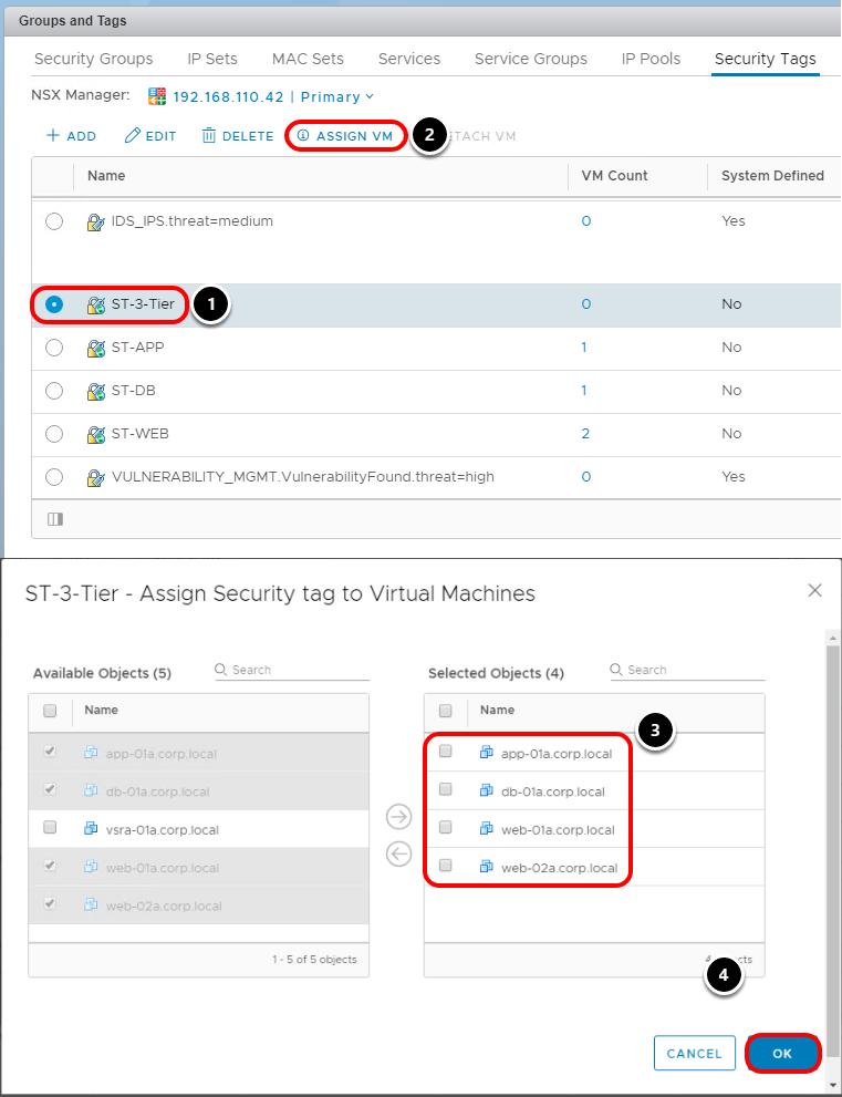
79 Page 79

80 1. Select ST-3-Tier 2. Click ASSIGN VM 3. Select on app-01a.corp.local, db-01a.corp.local, web-01a.corp.local and web-02a.corp.local 4. Click OK Create Universal Security Groups for Application Tiers 1. Click Security Groups 2. Click +ADD Page 80
81 Create New Universal Security Group and include Security Tag 1. Enter SG-WEB as the Name 2. Enable Universal Synchronization 3. Enable Active Standby Deployments 4. Click Select Objects to Include 5. Select Security Tag 6. Select ST-WEB Page 81
82 7. Click FINISH Repeat step 1 to 7 for creating security groups SG-APP and SG-DB. Use the security tag ST-APP for SG-APP and ST-DB for SG-DB as criteria. Create Security Group SG-3-Tier to wrap all the tiers of application 1. Enter SG-3-Tier as the Name Page 82
83 2. Enable Universal Synchronization 3. Enable Active Standby Deployments 4. Click Select Objects to Include 5. Select Security Tag 6. Select ST-3-Tier 7. Click FINISH Page 83

84 Verify Creation of Security Groups on Primary and Secondary NSX Managers As soon as you create the Security Groups on Primary NSX manager, the Universal Synchronization Service will push the Security Groups to the Secondary NSX manager. It Page 84

85 is important to validate that the synchronization is taking place across both NSX Managers. Select Secondary and ensure the Security Groups are synchronized from the Primary NSX manager Navigate to the Firewall Tab Navigate to the Firewall section 1. Click Firewall 2. Ensure that Primary is selected 3. Click Triple Dots 4. Click Add Section Above Page 85
86 Create Section 1. Enter Three Tier App as Section Name 2. Enable Universal Synchronization 3. Click ADD Page 86

87 Add a Universal Rule In the newly created Section, add a place holder for a universal rule 1. Click Triple Dots 2. Click Add Rule Page 87
 - We do not wish to filter for a particular source 2.")
88 Name the Rule 1. Enter Inbound Web Server into the text box Configure Destination 1. Leave the Source as Any (default setting) - We do not wish to filter for a particular source 2. Click Destination text box Page 88
89 3. Click Pencil icon Source is set to Any as we do not wish to filter for a particular source. Destination is modified to allow specific IP addresses. Configure Destination Security Group 1. Select Security Group 2. Select SG-WEB 3. Click SAVE Page 89

90 Configure Services for the rule 1. Verify Destination is configured according to previous step 2. Click Service text box 3. Click Pencil icon Define Services for the Rule Page 90
91 1. Select Services 2. Search https 3. Scroll down to find HTTPS 4. Select HTTPS 5. Click SAVE Apply the Rule to SG-WEB 1. Verify Service is configured according to previous step 2. Click Applied To text box 3. Click Pencil icon Page 91
92 Apply the Rule to SG-3-Tier 1. Select Security Group 2. Select SG-3-Tier 3. Click SAVE Page 92

93 Configure a Rule for Web to Application Server under previous rule 1. Click Triple Dots 2. Click Add Rule Below Page 93

94 Name the Rule 1. Enter Web to App in the text box Page 94

95 Configure the Source for the rule 1. Click Source text box 2. Click Pencil icon Page 95
96 Select SG-WEB as source 1. Select Security Group 2. Select SG-WEB 3. Click SAVE Page 96

97 Configure Destination Security Group 1. Verify Source is configured according to previous step 2. Click Destination text box 3. Click Pencil icon Page 97
98 Define the Destination as the App Tier Security Group 1. Select Security Group 2. Select SG-APP 3. Click SAVE Page 98

99 Configure Services for the Rule 1. Verify Destination is configured according to previous step 2. Click Service text box 3. Click Pencil icon Define Services for the Rule 1. Select Services 2. Enter tomcat as the keyword 3. Check Tomcat service Page 99

100 4. Click right arrow 5. Click SAVE Apply the Rule to SG-APP 1. Verify Service is configured according to previous step 2. Click Applied To text box 3. Click Pencil icon Page 100
101 Apply the Rule to SG-3-Tier 1. Select Security Group 2. Select SG-3-Tier 3. Click SAVE Page 101

102 Configure a Rule for Application to Database Server 1. Click Triple Dots 2. Click Add Rule Below Page 102

103 Name the Rule 1. Enter App to DB in the text box Page 103

104 Configure the Source 1. Click Source text box 2. Click Pencil icon Page 104
105 Select security group SG-APP created previously 1. Select Security Group 2. Select SG-APP 3. Click SAVE Page 105

106 Configure Destination 1. Verify Source is configured according to previous step 2. Click Destination text box 3. Click Pencil icon Page 106
107 Select Security Groups 1. Select Security Group 2. Select SG-DB 3. Click SAVE Page 107

108 Configure Service 1. Verify Destination is configured according to previous step 2. Click Service text box 3. Click Pencil icon Select HTTP Page 108
109 1. Select Services 2. Search http 3. Scroll down to find HTTP 4. Select HTTP 5. Click SAVE Apply the Rule to SG-3-Tier 1. Select Security Group 2. Select SG-3-Tier 3. Click SAVE Page 109

110 Configure Default Rule to reject every other traffic 1. Click Triple Dots 2. Click Add Rule Below Page 110

111 Name the Rule 1. Enter Block any to 3-Tier App in the text box Page 111
112 Change the destination of the Rule to SG-3-Tier 1. Select Security Group 2. Select SG-3-Tier 3. Click SAVE Page 112

113 Apply the Rule to SG-3-Tier 1. Select Security Group 2. Select SG-3-Tier 3. Click SAVE Edit the Action 1. Select Reject as the Action 2. Click Publish Page 113


114 Verify your rules are configured as above. Verify Creation on Secondary NSX Manager 1. Select Secondary 2. Verify that all rules appear in the Secondary NSX Manager Verify Application Connectivity 1. Click New Tab 2. Click webapp.corp.local Page 114

115 Verify Three Tier App Verify the Web Application is loaded and data is retrieved. Ping Application Virtual Machines To verify the default deny rule open a command prompt on the Main Console Page 115

116 Ping Each Virtual Machine Ping each virtual machine to verify the default deny rule. 1. ping ping ping No pings will be successful This concludes this section. In this section, we have configured Universal Distributed Firewall Rules and used Universal Security Groups to protect flows between the various tiers of the application across multiple sites. Universal Rules synchronize automatically from one site to another. Page 116
117 Navigate to the Networking & Security tab Navigate to the Networking & Security Section 1. Click Home icon 2. Click Networking & Security Page 117

118 Disable the 3-Tier-App Block Rule 1. Click Firewall 2. Expand Three Tier App Rules 3. Disable Rule 4. Click PUBLISH We will need to disable the default 3-Tier Block Rule in order for us to use Traceroute in the Next Module; we will be tracing the path from Main Console to Web Server VM. Page 118
119 Module 1 Conclusion This module walked you through the various pre-configured components of NSX in a multi-site configuration. You have also learned how to configure Locale ID, dynamic routing on UDLR, Universal Distributed Firewall rules and route filtering to favor one site over the other. The techniques used in this module are not the only way you can influence ingress/egress traffic. There are other ways to do it and we showed you one of the popular way to do it. You've finished Module 1 Congratulations on completing Module 1. You can proceed to Module 2 for configuring the SRM and performing partial and full failover of the application or End the Lab. For additional information on NSX Universal configurations and cross vc scenarios, visit the URL below and select the Cross-vCenter Installation Guide: Go to Lab Captain: Module 1 - TAY Wen Bin, Systems Engineer, Singapore Module 2 - TAY Wen Bin, Systems Engineer, Singapore How to End Lab To end the lab click on the END button. Page 119
120 Module 2 - Site Recovery Manager Configuration & Execution (45 Minutes) Page 120
121 Module Guidance In this module, students will learn how to configure the important SRM components such as Protection Groups, Folder Mappings, Resource Mappings, Recovery Plans, etc. In addition to configuring these various components, students will perform full failover of a 3-Tier application without changing IP addresses. IMPORTANT NOTE: IF YOU ARE TAKING MODULE 2 WITHOUT FIRST COMPLETING MODULE 1, THEN YOU MUST EXECUTE THE SCRIPT IN THE NEXT PAGE. If you have already completed Module 1, then you can skip the next step and proceed to "Creating SRM Protection Groups for Application". Page 121

122 Running the SRM FastForward Script Page 122
123 ONLY PERFORM THE STEP BELOW IF YOU INTEND TO SKIP DIRECTLY TO MODULE 2. IF YOU INTEND TO TAKE MODULE 1, THEN PROCEED TO 1. Right-Click on SRM FastForward.ps1 script placed on desktop of Main Console 2. Click on Run with PowerShell 3. Click 'Open" if a security warning pops up The script will perform the following configuration within the NSX environment: 1. Configure BGP Filters on RegionB0_Perimeter_GW 2. Configure Routing for Primary Universal Distributed Logical Router 3. Configure Routing for Secondary Universal Distributed Logical Router 4. Configure Unique Selection Criteria 5. Create Universal Security Tags 6. Create Universal Security Groups 7. Attach Universal Security Tags to VMs 8. Create Universal Distributed Firewall Rules Page 123

124 Script Execution Once the script has completed all the steps, press Enter to continue and the window will close by itself. This script will configure the lab and allow you to proceed to the next step. After this step, go back to the desktop and continue with the lab. Page 124
125 Creation of SRM protection groups for Application In this lab, the two vcenter Servers have been configured in Enhanced Linked Mode. This allows both vcenter Servers to be managed through the same vsphere Web Client session. While in Enhanced Linked Mode, both NSX environments can also be configured in the the same vsphere Web Client session. Login to the vsphere Web Client Open Google Chrome web browser. Login to vsphere Web Client and verify that you can access both vcenter Servers. 1. Enter as user name 2. Enter VMware1! as password 3. Click Login Page 125
126 Verify Both vcenter Servers Are Available Ensure that both vcenter Servers are visible You will now setup SRM Protection Groups and Protection Plans for the Web Application in order to be able to fail over the application. We have already setup vsphere Replication and replicated the VMs to Site B in order to save time. Navigate to Site Recovery 1. Click Home icon 2. Click Site Recovery Page 126


127 Configure Network Mappings As a part of the SRM configuration, network mappings are needed. These enable the recovery plan to connect VMs to the appropriate networks during a failover plan. Open Site Recovery 1. Click OPEN Site Recovery for 'vcsa-01a.corp.local' View Details of Site Recovery 1. Click VIEW DETAILS of 'vcsa-01a.corp.local <-> vcsa-01b.corp.local' Page 127

128 Navigate to Site A Network Mappings In this section of the lab, we will be mapping the networks on the protected site to networks on the recovery site. 1. Click Network Mappings 2. Click +NEW Page 128
129 Manual Mappings 1. Click Prepare Mappings Manually 2. Click Next Page 129
130 Expand Sites 1. Expand vcsa-01a.corp.local, RegionA01, RegionA01-vDS-COMP 2. Expand vcsa-01b.corp.local, RegionB01, RegionB01-vDS-COMP Page 130
131 Create Mappings Pay special attention to the following steps: The names of VXLAN port groups are too long, so we will use the Unique ID of the VXLAN Segments to identify the following logical switches: Web_Tier_ULS is universal wire ID 3 App_Tier_ULS is universal wire ID 4 DB_Tier_ULS is universal wire ID 5 We will perform the steps for universal wire ID 3 (Web_Tier-ULS) first. Do not click NEXT until you have perform the same steps for universal wire ID 4 (App_Tier_ULS) and universal wire ID 5 (DB_Tier_ULS): 1. Select universal wire ID 3 on Site A 2. Select universal wire ID 3 on Site B 3. Click Add Mappings Repeat step 1-3 for universal wire ID 4 (App_Tier_ULS) and universal wire ID 5 (DB_Tier_ULS). Page 131
132 Verify Mappings and Proceed 1. Verify that all the mappings to the Tiers are correct 2. Click NEXT Page 132
133 Reverse Mappings Reverse mappings will map the networks on the recovery site to networks on the protected site. In a failback scenario, we can quickly re-protect the VMs in the recovery site with the protected site by configuring reverse mappings. However, we will not be performing failback scenario in this lab, so we will not configure reserve mappings. 1. Click NEXT Page 133
134 Test Networks 1. Click NEXT Page 134
135 Ready to Complete 1. Click FINISH Page 135

136 Configure Folder Mappings You will now configure folder mappings for the SRM configuration. New Folder Mapping In this section of the lab, we are mapping the datacenters or virtual machine folders on the protected site to datacenters or virtual machine folders on the recovery site. 1. Click Folder Mappings 2. Click +NEW Page 136
137 Create Folder Mapping 1. Select Prepare mappings manually 2. Click NEXT Page 137
138 Prepare Mappings 1. Select RegionA01 2. Select RegionB01 3. Click ADD MAPPINGS 4. Click NEXT Page 138
139 Reverse Mapping Reverse mappings will map the datacenters or virtual machine folders on the recovery site to datacenters or virtual machine folders on the protected site. In a failback scenario, we can quickly re-protect the VMs in the recovery site with the protected site by configuring reverse mappings. However, we will not be performing failback scenario in this lab, so we will not configure reserve mappings. 1. Click NEXT Page 139
140 Finish Folder Mapping 1. Click FINISH Page 140

141 Configure Resource Mappings In this section, you will create resource mapping for the SRM configuration. Create new Resource map In this section of the lab, we are mapping the resource pools, standalone hosts, vapps, or clusters on the protected site to resource pools, standalone hosts, vapps, or clusters on the recovery site. You can map any type of resource on one site to any type of resource on the other site 1. Click Resource Mappings 2. Select +NEW Page 141
142 Prepare Mapping 1. Expand RegionA01 2. Expand RegionB01 3. Select RegionA01-COMP01 4. Select RegionB01-COMP01 5. Click ADD MAPPINGS 6. Click NEXT Page 142
143 Reverse Mapping Reverse mappings will map the resource pools, standalone hosts, vapps, or clusters on the recovery site to resource pools, standalone hosts, vapps, or clusters on the protected site. You can map any type of resource on one site to any type of resource on the other site In a failback scenario, we can quickly re-protect the VMs in the recovery site with the protected site by configuring reverse mappings. However, we will not be performing failback scenario in this lab, so we will not configure reserve mappings. 1. Click NEXT Page 143
144 Finish Resource Mappings 1. Click FINISH Page 144

145 Configure Placeholder Datastore You will now add the datastore configuration for the SRM configuration. Configure Placeholder Datastore If you use array-based protection groups or vsphere Replication protection groups, you must specify a placeholder datastore on the recovery site for Site Recovery Manager to use to store placeholder virtual machines. In this lab, we are using vsphere Replication protection group. 1. Click Placeholder Datastores 2. Click +NEW Page 145
146 Select the Datastore 1. Select RegionA01-ISCSI01-COMP01 2. Click ADD Page 146

147 Create Placeholder Store on RegionB01 1. Select vcsa-01b.corp.local 2. Click +NEW Page 147
148 Select Placeholder Datastore 1. Select RegionB01-ISCSI01-COMP01 2. Click ADD Page 148

149 Create Replications You will now create replications. Navigate to Replications 1. Click Replications 2. Click +NEW Page 149
150 Configure Replication 1. Select app-01a.corp.local 2. Select db-01a.corp.local 3. Select web-01a.corp.local 4. Select web-02a.corp.local 5. Click NEXT We will now create the replications for 4 VMs. Page 150
151 Target Site 1. Click NEXT Page 151
152 Target Datastore 1. Select RegionB01-ISCSI01-COMP01 2. Click NEXT Page 152
153 Replication Settings For the Recovery Point Objective (RPO) setting, you may adjust the sliding scale between 5 minutes and 24 hours. However, we will use the RPO setting as default. 1. Click NEXT Page 153
154 Protection Group 1. Select Do not add to protection group now 2. Click NEXT Page 154
155 Ready to Complete 1. Click FINISH Page 155

156 Create Protection Group You must now create the base protection group of the 3-Tier Application for the 4 VMs. Protection Groups You create protection groups to enable Site Recovery Manager to protect virtual machines. You can organize protection groups in folders. The Protection Groups tab displays the names of the protection groups, but does not display in which folder they are placed. If you have two protection groups with the same name in different folders, it might be difficult to tell them apart. Consequently, ensure that protection group names are unique across all folders. In environments in which not all users have view privileges for Page 156
157 all folders, to be sure of the uniqueness of protection group names, do not place protection groups in folders. 1. Select Protection Groups 2. Click +NEW Create New Protection for 3-Tier App 1. Enter 3-Tier-App as Name 2. Select vcsa-01a.corp.local -> vcsa-01b.corp.local 3. Click NEXT Page 157
158 Protection Group Type 1. Select Individual VMs (vsphere Replication) 2. Click NEXT Page 158
159 Virtual Machines 1. Select all VMs (app-01a.corp.local, db-01a.corp.local, web-01a.corp.local and web02a.corp.local) 2. Click NEXT Note that some of the VMs may show "Sync" instead of "OK" as the status. It is alright to proceed to the next step even if the VMs show "Sync" status. Page 159
160 Recovery Plan 1. Select Do not add to recovery plan now 2. Click NEXT We will not add this protection group to any recovery plan as we have not created any recovery plan. We will create the recovery plan and add the protection group in the next section. Page 160
161 Ready to Complete 1. Click FINISH When you create protection groups, wait to ensure that the operations finish as expected. Make sure that Site Recovery Manager creates the protection group and that the protection of the virtual machines in the group is successful Page 161

162 Create Recovery Plan In this section, we will create recovery plans for failing over the 3-Tier Application from Protected site to Recovery site. Navigate to Recovery Plans A recovery plan is like an automated run book. It controls every step of the recovery process, including the order in which Site Recovery Manager powers on and powers off virtual machines, the network addresses that recovered virtual machines use, and so on. Recovery plans are flexible and customizable. 1. Click Recovery Plans 2. Click +NEW Page 162
163 Name the Recovery Plan 1. Enter 3-Tier-App as Name 2. Select vcsa-01a.corp.local -> vcsa-01b.corp.local 3. Click NEXT Page 163
164 Select the Protection Group A recovery plan includes one or more protection groups. You can include a protection group in more than one recovery plan. For example, you can create one recovery plan to handle a planned migration of services from the protected site to the recovery site for the whole organization, and another set of plans per individual departments. In this example, having these different recovery plans referencing one protection group allows you to decide how to perform recovery. You can run only one recovery plan at a time to recover a particular protection group. If you test or run a recovery plan with a replication group that is shared in other recovery plans, the other recovery plans change the state of the protection group to Protection Group In Use and you cannot run them. 1. Select Protection groups for individual VMs or datastore groups 2. Select 3-Tier-App 3. Click NEXT Page 164
165 Test Networks 1. Click NEXT Page 165
166 Finish Creating the Recovery Plan 1. Click FINISH Page 166

167 Bring Down the Edge GW in RegionA0 In this section, you will shut down the RegionA0_Perimeter_GW to simulate a failure. In a real time environment, organizations can have multiple component failures. Those components could be any one of the listed below: 1. Controller Cluster Failure 2. Edge GW Failure 3. Physical Router Failure 4. WAN Link Failure 5. NSX Manager Failure 6. DCI Failure Within the scope of this lab we are not targeting all the failures. There is an excellent white paper that you can refer to which covers the possible failures within an environment. The white paper is available at the URL below: Navigate to vsphere Web Client 1. Click vsphere Web Client tab (we are switching back to the previous tab) Page 167
168 Navigate to Hosts and Clusters 1. Click Home icon 2. Click Hosts and Clusters Page 168

169 Shut Down the Edge GW 1. Expand vcsa-01a.corp.local 2. Expand RegionA01 3. Expand RegionA01-MGMT01 4. Click RegionA0_Perimeter_GW-0 5. Click Actions dropdown list 6. Click Power 7. Click Shut Down Guest OS 8. Click Yes to Confirm Guest Shut Down for 'RegionA0_Perimeter_GW-0' Page 169
170 Deploy OneArm-LB in RegionB0 In this section, we need to deploy the RegionB0-OneArm-LB to load balance the traffic for web-01a.corp.local and web-02a.corp.local. To save time, the RegionB0-OneArm-LB has already been pre-created in this lab. Hence we just need to deploy the RegionB0-OneArm-LB. Navigate to Networking & Security 1. Click Home icon 2. Click Networking & Security Page 170
. Note that if you do not see any NSX Managers, it means that you have login to vsphere Web client with the wrong username.")
171 Deploy One Arm LB on RegionB01 1. Click NSX Edges 2. Select (Role: Secondary) 3. Right-click RegionB0-OneArm-LB 4. Click Deploy 5. Click Yes to deploy the selected edge (RegionB0-OneArm-LB). Note that if you do not see any NSX Managers, it means that you have login to vsphere Web client with the wrong username. Please login with as username and VMware1! as password to view the NSX Edges in vsphere Web Client. Page 171

172 Run the Recovery Plan to Failover the site We will now run the recovery process for 3-Tier-App to failover the full application. Launch the vsphere Web Client for RegionB 1. Click New Tab 2. Click RegionB on the bookmarks toolbar 3. Click RegionB vcenter Note: Login to RegionB vcenter might take 2-3 minutes. Wait for the login to complete. This is a lab POD specific behavior and will not be present in real world vcenter. Page 172
173 Navigate to Site Recovery 1. Go Home icon 2. Click Site Recovery Open Site Recovery 1. Click OPEN Site Recovery on 'vcsa-01b.corp.local' Page 173


174 View Details of Site Recovery 1. Click VIEW DETAILS of 'vcsa-01b.corp.local <-> vcsa-01a.corp.local' Select 3-Tier-App 1. Click Recovery Plans 2. Select the radio button next to 3-Tier-App 3. Click RUN Page 174
175 Confirm Recovery Options 1. Check "I understand that this process will permanently alter the virtual machines and infrastructure..." 2. Click Disaster Recovery 3. Click NEXT Page 175
176 Execute the Plan 1. Click FINISH Page 176
177 Monitor Recovery Steps 1. Click 3-Tier-App 2. Click Recovery Steps Monitor the progress of the recovery plan. This could take 3-5 minutes to complete. Page 177

178 Recovery Complete 1. Click Summary When the recovery is completed, it will be reflected under Plan Status. Navigate to vsphere Web Client 1. Click vsphere Web Client tab for 'vcsa-01a.corp.local' Page 178
179 Configure BGP Filter on RegionB0_Perimeter_GW We will need to configure the BGP Filters to permit routes from /24 (Web), /24 (App), and /24 (DB). Navigate to Networking & Security 1. Click Home icon 2. Click Networking & Security Page 179
 3.")
180 Navigate to RegionB0 Perimeter GW 1. Click NSX Edges 2. Select (Role: Secondary) 3. Double-click RegionB0_Perimeter_GW Navigate to BGP Routing Page 180
181 1. Click Manage 2. Click Routing 3. Click BGP 4. Select (you may have to scroll down to see the neighbors) 5. Click Pencil icon If you do not see as the neighbor, return to the previous step and make sure to select Secondary NSX Manager. If you have selected Secondary NSX Manager, you should see as the neighbor. Page 181

182 Edit BGP Filters Page 182
183 1. Select /24 2. Click Pencil icon 3. Select Permit 4. Click OK Repeat Step 1-4 for /24 and /24. Verify BGP Filters 1. Verify BGP Filters are configured correctly 2. Click OK Page 183

184 Publish Changes 1. Click Publish Changes Open the Command Prompt 1. Click Command Prompt on the taskbar Run Traceroute from Main Console 1. Enter tracert Traceroute shows that the path to the Web VM is via the Perimeter GW and UDLR that are residing on recovery site (RegionB0). Page 184

185 Connect to 3-Tier App Let's check the connectivity to the application after the full failover Open a New Tab 1. Click New Tab Access the Application 1. Click webapp.corp.local Page 185

186 Verify Three Tier App Verify that the Hands on Labs Multi Tier Application page is loaded and data is retrieved. Ping Application Virtual Machines 1. Click Command Prompt icon Page 186

187 Ping Each Virtual Machine Ping each virtual machine to verify connectivity to the application 1. Ping Ping Ping All pings will be successful Page 187
188 Navigate to Hosts and Clusters 1. Click Home icon 2. Click Hosts and Clusters Page 188

189 Navigate to Hosts and Clusters Notice Web, App and DB virtual machines are residing in RegionB01 which is the recovery site. The application is accessible after the complete failover to RegionB01; no IP addresses of the VMs or firewall rules were changed. Page 189

190 Navigate to Networking and Security 1. Click Home icon 2. Click Networking and Security Page 190

191 Verify the VMs are automatically part of SG-WEB Security Group on Secondary Site 1. Click Firewall 2. Select Secondary 3. Expand Three Tier App firewall section 4. Click SG-WEB under Source Column Page 191
192 Verify web-01a,corp.local and web02a.corp.local are part of the Security Group Navigate to Hosts and Clusters 1. Click Home icon 2. Click Hosts and Clusters Page 192

193 Verify Security Tags 1. Select web-01a.corp.local Verify the Security Tags appear on web-01a.corp.local. The Security Tags are synchronized automatically from Primary NSX manager to Secondary NSX manager. Page 193
Table of Contents HOL SDC
 Table of Contents Lab Overview - - Site Recovery Manager: Data Center Migration and Disaster Recovery... 3 Overview of Site Recovery Manager... 4 Lab Overview... 5 Lab Guidance... 7 Module 1 - Lightning
NSX-T Data Center Migration Coordinator Guide. 5 APR 2019 VMware NSX-T Data Center 2.4
 NSX-T Data Center Migration Coordinator Guide 5 APR 2019 VMware NSX-T Data Center 2.4 You can find the most up-to-date technical documentation on the VMware website at: https://docs.vmware.com/ If you
Table of Contents HOL-1703-SDC-4
 Table of Contents Lab Overview - - VMware NSX: Installation and Configuration...2 Lab Guidance... 3 Module 1 - NSX Manager Installation and Configuration (15 Minutes)... 6 Introduction... 7 Hands-on Labs
Table of Contents HOL-1708-CHG-3
 Table of Contents Lab Overview - - Virtual SAN 6.2: Challenge Lab... 2 Lab Guidance... 3 Module Switcher... 8 Challenge 1 - Set Up a Virtual SAN Cluster (15 Mins)... 10 Introduction... 11 Module Switcher...
Table of Contents HOL-1710-SDC-6
 Table of Contents Lab Overview - - What's New: vsphere with Operations Management.. 2 Lab Guidance... 3 Module 1 - What's New in vsphere (90 minutes)... 9 vcenter Server Appliance (VSCA)... 10 vcenter
Table of Contents HOL-SDC-1412
 Table of Contents Lab Overview... 2 - IT Outcomes Data Center Virtualization and Standardization... 3 Module 1 - Lab Overview (15 Min)... 5 Physical Topology... 6 Application Topology... 8 Access the 3-Tier
Deploying VMware Validated Design Using OSPF Dynamic Routing. Technical Note 9 NOV 2017 VMware Validated Design 4.1 VMware Validated Design 4.
 Deploying VMware Validated Design Using PF Dynamic Routing Technical Note 9 NOV 2017 VMware Validated Design 4.1 VMware Validated Design 4.0 Deploying VMware Validated Design Using PF Dynamic Routing You
TECH SUMMIT START HERE
 TECH SUMMIT 2018 - START HERE Table of Contents 00 - Lab Introduction... 3 Accessing the Lab and Getting Support... 4 Kicking Things Off!... 6 vapp Architecture... 14 Labs Overview and Manuals Links...
Introducing VMware Validated Designs for Software-Defined Data Center
 Introducing VMware Validated Designs for Software-Defined Data Center VMware Validated Design 4.0 VMware Validated Design for Software-Defined Data Center 4.0 You can find the most up-to-date technical
Table of Contents. VMware AirWatch: Technology Partner Integration
 Table of Contents Lab Overview - HOL-1857-08-UEM - Workspace ONE UEM - Technology Partner Integration... 2 Lab Guidance... 3 Module 1 - F5 Integration with Workspace ONE UEM (30 min)... 9 Introduction...
Introducing VMware Validated Designs for Software-Defined Data Center
 Introducing VMware Validated Designs for Software-Defined Data Center VMware Validated Design for Software-Defined Data Center 4.0 This document supports the version of each product listed and supports
Table of Contents HOL-1757-MBL-6
 Table of Contents Lab Overview - - VMware AirWatch: Technology Partner Integration... 2 Lab Guidance... 3 Module 1 - F5 Integration with AirWatch (30 min)... 8 Getting Started... 9 F5 BigIP Configuration...
21CTL Disaster Recovery, Workload Mobility and Infrastructure as a Service Proposal. By Adeyemi Ademola E. Cloud Engineer
 21CTL Disaster Recovery, Workload Mobility and Infrastructure as a Service Proposal By Adeyemi Ademola E. Cloud Engineer 1 Contents Introduction... 5 1.2 Document Purpose and Scope...5 Service Definition...
VMware AirWatch: Directory and Certificate Authority
 Table of Contents Lab Overview - HOL-1857-06-UEM - VMware AirWatch: Directory and Certificate Authority Integration... 2 Lab Guidance... 3 Module 1 - Advanced AirWatch Configuration, AD Integration/Certificates
Table of Contents HOL-1701-CHG-5
 Table of Contents Lab Overview: vrealize Operations Application Monitoring: Challenge Lab... 2 Lab Overview... 3 Lab Guidance... 5 Module 1 - Configuring a Custom Application (15 minutes)... 10 Introduction...
Table of Contents HOL NET
 Table of Contents Lab Overview - - VMware NSX-T Data Center Operations, Troubleshooting and API Consumption... 2 Lab Guidance... 3 Module 1 - NSX-T Datacenter Operations - Use Tools within NSX-T Datacenter
VMware Validated Design Site Protection and Recovery Guide
 VMware Validated Design Site Protection and Recovery Guide VMware Validated Design for Software- Defined Data Center 3.0 This document supports the version of each product listed and supports all subsequent
2V0-642 vmware. Number: 2V0-642 Passing Score: 800 Time Limit: 120 min.
 2V0-642 vmware Number: 2V0-642 Passing Score: 800 Time Limit: 120 min Exam A QUESTION 1 A network administrator has been tasked with deploying a 3-tier application across two data centers. Tier-1 and tier-2
IBM Cloud for VMware Solutions NSX Edge Services Gateway Solution Architecture
 IBM Cloud for VMware Solutions NSX Edge Services Gateway Solution Architecture Date: 2017-03-29 Version: 1.0 Copyright IBM Corporation 2017 Page 1 of 16 Table of Contents 1 Introduction... 4 1.1 About
VMware AirWatch - Workspace ONE, Single Sign-on and VMware Identity Manager
 VMware AirWatch - Workspace ONE, Single Sign-on and VMware Identity Table of Contents Lab Overview - HOL-1857-03-UEM - Workspace ONE UEM with App & Access Management... 2 Lab Guidance... 3 Module 1 - Workspace
Introducing VMware Validated Designs for Software-Defined Data Center
 Introducing VMware Validated Designs for Software-Defined Data Center VMware Validated Design for Software-Defined Data Center 3.0 This document supports the version of each product listed and supports
Workload Mobility and Disaster Recovery to VMware Cloud IaaS Providers
 VMware vcloud Architecture Toolkit for Service Providers Workload Mobility and Disaster Recovery to VMware Cloud IaaS Providers Version 2.9 January 2018 Adrian Roberts 2018 VMware, Inc. All rights reserved.
Dell EMC. VxBlock Systems for VMware NSX 6.2 Architecture Overview
 Dell EMC VxBlock Systems for VMware NSX 6.2 Architecture Overview Document revision 1.6 December 2018 Revision history Date Document revision Description of changes December 2018 1.6 Remove note about
Quick Start Guide (SDN)
") NetBrain Integrated Edition 7.1 Quick Start Guide (SDN) Version 7.1a Last Updated 2018-09-03 Copyright 2004-2018 NetBrain Technologies, Inc. All rights reserved. Contents 1. Discovering and Visualizing
NetBrain Integrated Edition 7.1 Quick Start Guide (SDN) Version 7.1a Last Updated 2018-09-03 Copyright 2004-2018 NetBrain Technologies, Inc. All rights reserved. Contents 1. Discovering and Visualizing
Managing VMware vcenter Site Recovery Manager
 Managing VMware vcenter Site Recovery Manager This chapter contains the following sections: About VMware vcenter Site Recovery Manager, page 1 Overview of SRM Configuration, page 2 Integrating SRM with
Table of Contents HOL-PRT-1305
 Table of Contents Lab Overview... 2 - Abstract... 3 Overview of Cisco Nexus 1000V series Enhanced-VXLAN... 5 vcloud Director Networking and Cisco Nexus 1000V... 7 Solution Architecture... 9 Verify Cisco
VMware Integrated OpenStack Quick Start Guide
 VMware Integrated OpenStack Quick Start Guide VMware Integrated OpenStack 1.0.1 This document supports the version of each product listed and supports all subsequent versions until the document is replaced
Cisco Virtual Application Container Services 2.0 Lab v1
 Cisco Virtual Application Container Services 2.0 Lab v1 Last Updated: 02-SEP-2015 About This Solution Cisco Virtual Application Container Services (VACS) enables simplified deployment of Secure Application
Disclaimer This presentation may contain product features that are currently under development. This overview of new technology represents no commitme
 SAI2803BU The Road to Micro- Segmentation with VMware NSX #VMworld #SAI2803BU Disclaimer This presentation may contain product features that are currently under development. This overview of new technology
vcloud Director Tenant Portal Guide vcloud Director 8.20
 vcloud Director Tenant Portal Guide vcloud Director 8.20 You can find the most up-to-date technical documentation on the VMware website at: https://docs.vmware.com/ If you have comments about this documentation,
How to Deploy vcenter on the HX Data Platform
 First Published: 2016-07-11 Last Modified: 2019-01-08 vcenter on HyperFlex Cisco HX Data Platform deployment, including installation and cluster configuration and management, requires a vcenter server
Configuring ApplicationHA in VMware SRM 5.1 environment
 Configuring ApplicationHA in VMware SRM 5.1 environment Windows Server 2003 and 2003 R2, Windows Server 2008 and 2008 R2 6.0 September 2013 Contents Chapter 1 About the ApplicationHA support for VMware
Introducing VMware Validated Designs for Software-Defined Data Center
 Introducing VMware Validated Designs for Software-Defined Data Center 13 FEB 2018 VMware Validated Design 4.2 VMware Validated Design for Software-Defined Data Center 4.2 You can find the most up-to-date
Table of Contents HOL SLN
 Table of Contents Lab Overview - - Modernizing Your Data Center with VMware Cloud Foundation... 3 Lab Guidance... 4 Module 1 - Deploying VMware Cloud Foundation (15 Minutes)... 7 Introduction... 8 Hands-on
Table of Contents HOL CMP
 Table of Contents Lab Overview - - vrealize Orchestrator - Advanced... 2 Lab Guidance... 3 Module 1 - Creating Advanced vrealize Orchestrator Workflows (45 min)...9 Introduction... 10 Prompting User Input
Cross-vCenter NSX Installation Guide. Update 4 VMware NSX for vsphere 6.4 VMware NSX Data Center for vsphere 6.4
 Cross-vCenter NSX Installation Guide Update 4 VMware NSX for vsphere 6.4 VMware NSX Data Center for vsphere 6.4 You can find the most up-to-date technical documentation on the VMware website at: https://docs.vmware.com/
Table of Contents HOL SLN
 Table of Contents Lab Overview - - Modernizing Data Center for Maximum Business Flexibility... 2 Lab Guidance... 3 Module 1 - Introduction to Modernizing the Data Center (15 minutes)... 9 Introduction...
Introducing VMware Validated Designs for Software-Defined Data Center
 Introducing VMware Validated Designs for Software-Defined Data Center 17 JUL 2018 VMware Validated Design 4.3 VMware Validated Design for Software-Defined Data Center 4.3 You can find the most up-to-date
Cross-vCenter NSX Installation Guide. Update 3 Modified on 20 NOV 2017 VMware NSX for vsphere 6.2
 Cross-vCenter NSX Installation Guide Update 3 Modified on 20 NOV 2017 VMware NSX for vsphere 6.2 You can find the most up-to-date technical documentation on the VMware website at: https://docs.vmware.com/
Storage Replication Adapter for VMware vcenter SRM. April 2017 SL10334 Version 1.5.0
 Storage Replication Adapter for VMware vcenter SRM April 2017 SL10334 Version 1.5.0 1 Introduction This lab introduces the fundamentals of VMware vcenter Site Recovery Manager on clustered Data ONTAP.
Cross-vCenter NSX Installation Guide. Update 6 Modified on 16 NOV 2017 VMware NSX for vsphere 6.3
 Cross-vCenter NSX Installation Guide Update 6 Modified on 16 NOV 2017 VMware NSX for vsphere 6.3 You can find the most up-to-date technical documentation on the VMware website at: https://docs.vmware.com/
HOW TO BUILD A NESTED NSX-T 2.3 LAB
 TECHNICAL WHITE PAPER -FEBRUARY 2019 HOW TO BUILD A NESTED NSX-T 2.3 LAB Explore the features and capabilities of VMware NSX-T Jim Streit, VCIX-NV NSX Senior Technical Account Specialist (TAS) VMware Professional
vcenter Operations Management Pack for NSX-vSphere
 vcenter Operations Management Pack for NSX-vSphere vcenter Operations Manager 5.8 This document supports the version of each product listed and supports all subsequent versions until the document is replaced
VMware vsphere 5.5: Install, Configure, Manage Lab Addendum. Lab 3: Configuring VMware ESXi
 VMware vsphere 5.5: Install, Configure, Manage Lab Addendum Lab 3: Configuring VMware ESXi Document Version: 2014-07-08 Copyright Network Development Group, Inc. www.netdevgroup.com NETLAB Academy Edition,
Table of Contents HOL CMP
 Table of Contents Lab Overview - - Monitor and Troubleshoot Your Infrastructure and Applications with vrealize Operations and vrealize Log Insight... 2 Lab Guidance... 3 Module 1 - Troubleshoot Infrastructure
Planning and Preparation. VMware Validated Design 4.0 VMware Validated Design for Remote Office Branch Office 4.0
 VMware Validated Design 4.0 VMware Validated Design for Remote Office Branch Office 4.0 You can find the most up-to-date technical documentation on the VMware website at: https://docs.vmware.com/ If you
Parallel to NSX Edge Using VXLAN Overlays with Avi Vantage for both North-South and East-West Load Balancing Using Transit-Net
 Page 1 of 11 Parallel to NSX Edge Using VXLAN Overlays with Avi Vantage for both North-South and East-West Load Balancing Using Transit-Net view online In this topology, the Avi SE is installed parallel
Table of Contents HOL NET
 Table of Contents Lab Overview - - Getting Started with vrealize Network Insight... 2 Lab Guidance... 3 Module 1 - Micro-Segmentation and Security (30 minutes)... 9 Introduction... 10 Micro-Segmentation
Disclaimer This presentation may contain product features that are currently under development. This overview of new technology represents no commitme
 NET1416BE NSX Logical Routing Yves Hertoghs Pooja Patel #VMworld #NET1416BE Disclaimer This presentation may contain product features that are currently under development. This overview of new technology
NexentaStor Storage Replication Adapter User Guide
 NexentaStor 5.1.1 Storage Replication Adapter User Guide Date: January, 2018 Part Number: 3000-nxs-SRA-User-Guide-5.1.1-000092-A Copyright 2018 Nexenta Systems TM, ALL RIGHTS RESERVED Notice: No part of
Table of Contents HOL-HBD-1301
 Table of Contents Lab Overview... 2 - vcloud Hybrid Service Jump Start for vsphere Admins...3 Module 1 - vcloud Hybrid Service: Architecture and Consumption Principles...5 vcloud Hybrid Service... 6 vcloud
Basic Configuration Installation Guide
 RecoverPoint for VMs 5.1 Basic Configuration Installation Guide P/N 302-003-975 REV 1 July 4, 2017 This document contains information on these topics: Revision History... 2 Overview... 3 Reference architecture...
VMware vcenter Site Recovery Manager 4.1 Evaluator s Guide EVALUATOR'S GUIDE
 VMware vcenter Site Recovery Manager 4.1 EVALUATOR'S GUIDE Table of Contents. Getting Started.... 3 About VMware vcenter Site Recovery Manager.... 3 About This Guide.... 3 Intended Audience.... 3 Assumptions....
Configure RSPAN with VMware
 Configure RSPAN with VMware Published: 2018-04-19 The Remote Switched Port Analyzer (RSPAN) enables you to monitor traffic on one switch through a device on another switch and then send the monitored traffic
IaaS Integration for Multi- Machine Services. vrealize Automation 6.2
 IaaS Integration for Multi- Machine Services vrealize Automation 6.2 You can find the most up-to-date technical documentation on the VMware website at: https://docs.vmware.com/ If you have comments about
Basic Configuration Installation Guide
 EMC RecoverPoint for VMs 5.0 Basic Configuration Installation Guide P/N 302-003-534 REV 01 December 7, 2016 This document contains information on these topics: Revision History... 2 Overview... 3 Reference
Customer Onboarding with VMware NSX L2VPN Service for VMware Cloud Providers
 VMware vcloud Network VMware vcloud Architecture Toolkit for Service Providers Customer Onboarding with VMware NSX L2VPN Service for VMware Cloud Providers Version 2.8 August 2017 Harold Simon 2017 VMware,
Cisco VDS Service Broker Software Installation Guide for UCS Platforms
 Cisco VDS Service Broker 1.0.1 Software Installation Guide for UCS Platforms Revised: May 2013 This document provides detailed instructions for installing the Cisco Videoscape Distribution Suite Service
NSX Administration Guide. Update 3 Modified on 20 NOV 2017 VMware NSX for vsphere 6.2
 NSX Administration Guide Update 3 Modified on 20 NOV 2017 VMware NSX for vsphere 6.2 You can find the most up-to-date technical documentation on the VMware website at: https://docs.vmware.com/ If you have
Cisco ACI vcenter Plugin
 This chapter contains the following sections: About Cisco ACI with VMware vsphere Web Client, page 1 Getting Started with, page 2 Features and Limitations, page 7 GUI, page 12 Performing ACI Object Configurations,
SRM Evaluation Guide First Published On: Last Updated On:
 First Published On: 12-24-2016 Last Updated On: 04-17-2018 1 Table of Contents 1. Introduction 1.1.Overview 1.2.Terminology 1.3.About This Evaluation Guide 2. Requirements 2.1.Overview 3. Evaluation Workflow
Planning and Preparation. Modified on 21 DEC 2017 VMware Validated Design 4.1 VMware Validated Design for Micro-Segmentation 4.1
 Modified on 21 DEC 2017 VMware Validated Design 4.1 VMware Validated Design for Micro-Segmentation 4.1 You can find the most up-to-date technical documentation on the VMware website at: https://docs.vmware.com/
Planning and Preparation
 VMware Validated Design for Micro-Segmentation 4.0 This document supports the version of each product listed and supports all subsequent versions until the document is replaced by a new edition. To check
Ordering and deleting Single-node Trial for VMware vcenter Server on IBM Cloud instances
 Ordering and deleting Single-node Trial for VMware vcenter Server on IBM Cloud instances The Single-node Trial for VMware vcenter Server on IBM Cloud is a single-tenant hosted private cloud that delivers
VMWARE TUNNEL AND VMWARE NSX MICRO-SEGMENTATION INTEGRATION GUIDE. VMware AirWatch Enterprise Mobility Management 9.1
 TECHNICAL WHITE PAPER SEPTEMBER 2017 VMWARE TUNNEL AND VMWARE NSX MICRO-SEGMENTATION INTEGRATION GUIDE VMware AirWatch Enterprise Mobility Management 9.1 Table of Contents Introduction.... 4 Purpose...4
IaaS Integration for Multi-Machine Services
 IaaS Integration for Multi-Machine Services vcloud Automation Center 6.1 This document supports the version of each product listed and supports all subsequent versions until the document is replaced by
What s New in VMware vcloud Director 8.20
 What s New in VMware vcloud Director 8.20 Feature Overview TECHNICAL WHITE PAPER Table of Contents Introduction.... 3 Feature Updates.... 3 Advanced NSX Networking Features.... 3 Custom Role-Based Access
Dell EMC. VxBlock Systems for VMware NSX 6.3 Architecture Overview
 Dell EMC VxBlock Systems for VMware NSX 6.3 Architecture Overview Document revision 1.1 March 2018 Revision history Date Document revision Description of changes March 2018 1.1 Updated the graphic in Logical
Disclaimer This presentation may contain product features that are currently under development. This overview of new technology represents no commitme
 STO2451BU Automating Disaster Recovery Operations in the SDDC with SRM, vrealize Automation, and NSX VMworld 2017 Shobhan Lakkapragada Director of Product Management Stefan Tsonev Director of Engineering
WHITE PAPER SEPTEMBER 2017 VCLOUD DIRECTOR 9.0. What s New
 WHITE PAPER SEPTEMBER 2017 VCLOUD DIRECTOR 9.0 What s New Contents Summary 3 Features Update 3 Enhanced User Interface.................................................... 3 Multisite Management.......................................................
DESIGN GUIDE. VMware NSX for vsphere (NSX-v) and F5 BIG-IP Design Guide
 and F5 BIG-IP Design Guide") VMware NSX for vsphere (NSX-v) and F5 BIG-IP Design Guide Contents Intended Audience 3 Overview 3 NSX and BIG-IP Topology Options 4 Topology 1: Parallel to NSX Edge Using VXLAN Overlays with BIG-IP Physical
VMware NSX for vsphere (NSX-v) and F5 BIG-IP Design Guide Contents Intended Audience 3 Overview 3 NSX and BIG-IP Topology Options 4 Topology 1: Parallel to NSX Edge Using VXLAN Overlays with BIG-IP Physical
Upgrading from TrafficShield 3.2.X to Application Security Module 9.2.3
 Upgrading from TrafficShield 3.2.X to Application Security Module 9.2.3 Introduction Preparing the 3.2.X system for the upgrade Installing the BIG-IP version 9.2.3 software Licensing the software using
TECHNICAL WHITE PAPER - FEBRUARY VMware Site Recovery for VMware Cloud on AWS Evaluation Guide TECHNICAL WHITE PAPER
 TECHNICAL WHITE PAPER - FEBRUARY 2019 VMware Site Recovery for VMware Cloud on AWS Evaluation Guide TECHNICAL WHITE PAPER Table of Contents Introduction 4 Pre-requisites 4 Site Recovery Manager Server...
vrealize Operations Management Pack for NSX for vsphere 3.5 Release Notes
 vrealize Operations Management Pack for NSX for vsphere 3.5 Release Notes Build: 4602207 Last document update: 14 November, 2016 Contents: Before You Install the Management Pack Upgrading from the Management
vrealize Operations Management Pack for NSX for vsphere 3.5.0
 vrealize Operations Management Pack for NSX for vsphere 3.5.0 This document supports the version of each product listed and supports all subsequent versions until the document is replaced by a new edition.
Table of Contents HOL CHG
 Table of Contents Lab Overview - - vsphere Challenge Lab... 2 Lab Guidance... 3 Module 1 - Let's Start with the Basics (30 minutes)... 8 Introduction... 9 Can't vmotion a VM... 11 Can't ping a VM... 18
Parallel to NSX Edge Using Avi Vantage for North-South and East-West Load Balancing
 Page 1 of 10 Parallel to NSX Edge Using Avi Vantage for North-South and East-West Load Balancing view online In this topology the Avi SE is installed parallel to NSX Edge. Physically, the Avi SE gets deployed
TECHNICAL WHITE PAPER - MAY 2017 MULTI DATA CENTER POOLING WITH NSX WHITE PAPER
 TECHNICAL WHITE PAPER - MAY 2017 MULTI DATA CENTER POOLING WITH NSX WHITE PAPER Table of Contents Executive Summary 3 NSX with vsphere Metro Storage Cluster (vmsc) 4 Cross-VC NSX 6 Layer 2 VPN (L2VPN)
Table of Contents HOL-SDC-1415
 Table of Contents Lab Overview - - IT Outcomes Security Controls Native to Infrastructure. 2 Lab Guidance... 3 Module 1 - Policy-Based Compliance... 5 Introduction... 6 Manage vcenter Server Virtual Machines...
vsphere Networking Update 2 VMware vsphere 5.5 VMware ESXi 5.5 vcenter Server 5.5 EN
 Update 2 VMware vsphere 5.5 VMware ESXi 5.5 vcenter Server 5.5 This document supports the version of each product listed and supports all subsequent versions until the document is replaced by a new edition.
Virtual Storage Console, VASA Provider, and Storage Replication Adapter for VMware vsphere
 Virtual Storage Console, VASA Provider, and Storage Replication Adapter for VMware vsphere Workflow Guide for 7.2 release July 2018 215-13170_B0 doccomments@netapp.com Table of Contents 3 Contents Deciding
Getting Started Guide. VMware NSX Cloud services
 VMware NSX Cloud services You can find the most up-to-date technical documentation on the VMware website at: https://docs.vmware.com/ If you have comments about this documentation, submit your feedback
Securing VMware NSX MAY 2014
 Securing VMware NSX MAY 2014 Securing VMware NSX Table of Contents Executive Summary... 2 NSX Traffic [Control, Management, and Data]... 3 NSX Manager:... 5 NSX Controllers:... 8 NSX Edge Gateway:... 9
Disclaimer This presentation may contain product features that are currently under development. This overview of new technology represents no commitme
 NET1192BE Multisite Networking & Security with Cross-vC NSX Josh Coulling Networking & Security Senior System Engineer #VMworld #NET1192BE Disclaimer This presentation may contain product features that
Introduction to Virtualization
 Introduction to Virtualization Module 2 You Are Here Course Introduction Introduction to Virtualization Creating Virtual Machines VMware vcenter Server Configuring and Managing Virtual Networks Configuring
Configure RSPAN with VMware
 Configure RSPAN with VMware Published: 2019-01-07 The Remote Switched Port Analyzer (RSPAN) enables you to monitor traffic on one switch through a device on another switch and then send the monitored traffic
Horizon Console Administration. 13 DEC 2018 VMware Horizon 7 7.7
 Horizon Console Administration 13 DEC 2018 VMware Horizon 7 7.7 You can find the most up-to-date technical documentation on the VMware website at: https://docs.vmware.com/ If you have comments about this
Dell Storage PS Series Administration and Product Overview
 Dell Storage PS Series Administration and Product Overview Dell Storage Hands-on Lab Instructions Total estimated time: varies. This lab consists of multiple non-dependent modules that can be completed
vrealize Operations Management Pack for NSX for vsphere Release Notes
 vrealize Operations Management Pack for NSX for vsphere 3.1.1 Release Notes Build: 4247401 Last document update: 24 August 2016 Contents: Upgrading from the Management Pack for NSX for vsphere 2.0 What's
IPv6 Best Operational Practices of Network Functions Virtualization (NFV) With Vmware NSX. Jeremy Duncan Tachyon Dynamics
 With Vmware NSX. Jeremy Duncan Tachyon Dynamics") IPv6 Best Operational Practices of Network Functions Virtualization (NFV) With Vmware NSX Jeremy Duncan Tachyon Dynamics Overview NSX as it pertains to NFV How NSX works NSX IPv6 Capabilities & Limitations
IPv6 Best Operational Practices of Network Functions Virtualization (NFV) With Vmware NSX Jeremy Duncan Tachyon Dynamics Overview NSX as it pertains to NFV How NSX works NSX IPv6 Capabilities & Limitations
Table of Contents HOL NET
 Table of Contents - VMware AppDefense - Secure Datacenter Endpoints...2 Lab Guidance... 3 Module 1- Overview of VMware AppDefense (15 Minutes)... 9 AppDefense Platform Overview... 10 Conclusion... 14 Module
Design Guide: Deploying NSX for vsphere with Cisco ACI as Underlay
 Design Guide: Deploying NSX for vsphere with Cisco ACI as Underlay Table of Contents Executive Summary... 2 Benefits of NSX Architecture... 4 2.1 NSX Primary Use Cases... 4 2.2 Logical Layer Connectivity...
vsphere Networking Update 1 ESXi 5.1 vcenter Server 5.1 vsphere 5.1 EN
 Update 1 ESXi 5.1 vcenter Server 5.1 vsphere 5.1 This document supports the version of each product listed and supports all subsequent versions until the document is replaced by a new edition. To check
VMware Validated Design for NetApp HCI
 Network Verified Architecture VMware Validated Design for NetApp HCI VVD 4.2 Architecture Design Sean Howard Oct 2018 NVA-1128-DESIGN Version 1.0 Abstract This document provides the high-level design criteria
Disclaimer This presentation may contain product features that are currently under development. This overview of new technology represents no commitme
 LHC2103BU NSX and VMware Cloud on AWS: Deep Dive Ray Budavari, Senior Staff Technical Product Manager NSX @rbudavari #VMworld #LHC2103BU Disclaimer This presentation may contain product features that are
Dell Storage Compellent Integration Tools for VMware
 Dell Storage Compellent Integration Tools for VMware Administrator s Guide Version 3.1 Notes, Cautions, and Warnings NOTE: A NOTE indicates important information that helps you make better use of your
Installing and Configuring vcloud Connector
 Installing and Configuring vcloud Connector vcloud Connector 2.6.0 This document supports the version of each product listed and supports all subsequent versions until the document is replaced by a new
Exam Questions VCPN610
 Exam Questions VCPN610 VMware Certified Professional Network Virtualization https://www.2passeasy.com/dumps/vcpn610/ 1. Where are the distributed NSX firewall decisions logged? A. NSX Manager B. vcenter
Table of Contents HOL-PRT-1467
 Table of Contents Lab Overview - - Virtual Volumes with Dell EqualLogic... 2 Lab Guidance... 3 Pre-flight Instructions... 5 Module 1 - Working with Dell EqualLogic and VVOLs (60 Mins)... 11 Creating a
Planning and Preparation. 17 JUL 2018 VMware Validated Design 4.3 VMware Validated Design for Software-Defined Data Center 4.3
 17 JUL 2018 VMware Validated Design 4.3 VMware Validated Design for Software-Defined Data Center 4.3 You can find the most up-to-date technical documentation on the VMware website at: https://docs.vmware.com/