Telecommunications 3 Module 6
|
|
|
- Amber Roberts
- 5 years ago
- Views:
Transcription
1 Overview Compared to wired LANs, wireless LANs (WLANs) have unique characteristics. First, the physical characteristics of a wireless LAN introduce range limitations and unreliable media, dynamic topologies where stations move about, interference from outside sources, and the inability for every device to hear every other device within the WLAN. From the point of view of WLAN scalability, this module covers two key considerations concerning the scalability of wireless networks: QoS and security. In the past, WLANs handled the transport of low-bandwidth, data application traffic. Today, with the expansion of WLANs into enterprise and vertical (retail, finance, education) markets, WLANs are now used to transport high-bandwidth, intensive data applications in conjunction with time-sensitive multimedia applications. This requirement has led to the necessity for wireless QoS. This module begins by describing how Cisco has met the challenges of QoS deployment in WLANs. With increased reliance on WLANs, businesses are becoming more concerned about network security. Network managers need to provide end users with freedom and mobility without offering intruders access to the WLAN or the information sent and received on the wireless network. The rest of this module describes wireless security standards and the importance of wireless LAN (WLAN) security. It also defines and describes the 802.1x standard and various authentication processes. The module concludes with a description of basic WLAN management and configuration tasks using the Cisco Wireless Control System (WCS) A Standard for WLAN QoS WLANs, whether they are overlays to or substitutes for traditional wired LANs, are based on standard The standard extends to the wireless domain, though with some complications. Figure depicts a typical WLAN extension to a wired LAN and highlights areas that require special consideration: Both WLANs and wired LANs define the physical and data link layers and use MAC addresses. LANs and WLANS use many of the same protocols and applications. Examples of such protocols are the IP and IPsec protocols for VPNs. Examples of applications are web, FTP, and Simple Network Management Protocol (SNMP). WLANs use carrier sense multiple access with collision avoidance (CSMA/CA) technology instead of the carrier sense multiple access with collision detection (CSMA/CD) technology that Ethernet LANs use. Collision detection is not possible in wireless applications because a sending station cannot receive at the same time that the station is transmitting and, therefore, cannot detect a collision. Wireless LANs try to avoid collisions instead of dealing with them after the fact, as is the case in Wireless uses a Distributed Coordination Function (DCF) to avoid collisions with the use of radio frequency (RF) carrier sense, interframe spacing, and random wait timers to avoid collisions. LANs commonly use Layer 3 differentiated services code point (DSCP) or Layer p to ensure priority and provide quality of service (QoS). WLANs can use e. The original standards aimed to provide best effort data communication without QoS support. The new e standard is an extension of that provides more consistent, quality RF transmission for voice and video devices operate either in a peer-to-peer fashion or integrated with an existing wired LAN devices often operate within overlapping WLANs. The mobility requirements of devices must be met if operation from moving vehicles is to be considered must provide privacy and security of user data. Figure shows the relationship between the OSI reference model and the IEEE Standard. Figures and list amendments to the original IEEE Standard affecting 1


2 wireless LAN. This lesson examines e in detail. 2


3 6.1.2WLAN QoS Description The IEEE standardized e in 2005 as a set of technologies for prioritizing traffic and preventing packet collisions and delays to improve voice and video performance over WLANs. The e specification uses the same eight priority level structure that p uses. They are grouped into four access categories or traffic classes as follows: Voice: Priority 7 or 6 for toll-quality VoIP calls requiring low latency Video: Priority 5 or 4 for SDTV or HDTV video streams Best Effort: Priority 3 or 0 for latency-insensitive, interactive applications Background: Priority 2 or 1 for batch data transfer applications and indicates less than best effort treatment Each access level provides a separate queue. To identify the class of each packet, the standard uses markers that are similar to markers used in wired Ethernet. Seeing those markers, an access point handles packets according to the packet s assigned priority. 3
4 To speed the adoption of QoS in the marketplace, the Wi-Fi Multimedia (WMM) was implemented before the e standard was approved. WMM is a subset of the e standard using four access categories rather than the eight priority values of e. By default, these are voice, video, best effort, and background, but definitions of the four classes can be changed from the default definitions. WMM provides a group of features for wireless networks to improve audio, video, and voice application performances. The resulting QoS allows translation from 802.1p or differentiated services code point (DSCP) to the appropriate RF techniques giving high-priority traffic an increased probability of RF transmission over lower-priority traffic. WMM uses traffic-prioritization capabilities based on the four defined access categories. RF prioritization gives a higher access category the increased probability of being transmitted first. This allows the platinum level to obtain RF access for transmission before the gold, silver, or bronze levels. The access categories correspond to 802.1p or DSCP priorities to facilitate interoperability with QoS policy-management mechanisms. WMM priorities coexist with legacy devices that are not WMM-enabled. Packets that are not assigned to a specific access category are categorized by default as the best-effort access category. Figure depicts the WMM traffic prioritization scheme that the Wi-Fi Alliance has approved for assigning application data that is being sent to the client. WMM is an enhancement to the MAC sublayer that adds QoS functionality to Wi-Fi networks. The MAC sublayer handles access mechanisms, fragmentation, and encryption. WMM prioritization maps four independent transmit queues to eight 802.1e priority levels, as shown in Figure. 4


5 6.1.3WLAN QoS RF Backoff Timing The fundamental access method of is CSMA/CA. CSMA/CA works by a "listen before talk scheme." WMM uses the CSMA/CA-based distributed coordination function (DCF) mechanism that gives all devices the same priority and is based on a best-effort, listenbefore-talk algorithm. If the medium is not busy, the transmission may proceed. CSMA/CA 5

6 uses a random backoff time to avoid collisions among stations sharing the medium, if the sending station s physical or logical sensing mechanism indicates a busy medium. Each client waits a random backoff time and then transmits only if no other device is transmitting at that time. This collision-avoidance method gives all the devices the opportunity to transmit, but when traffic demand is high and networks can become overloaded, the performance of all devices will be affected. Using Enhanced DCF (EDCF), WMM stipulates different fixed and random wait times for the four access categories to provide more favorable network access for applications that are less tolerant of packet delays. Devices that have less time to wait have a better chance of being able to transmit than those that have a longer wait. The access categories voice, video, best effort and background map to Ethernet 802.1d prioritization tags to allow consistent QoS across wireless and wired network segments. WMM provides priority access to the RF medium in two ways: First, the wireless access point must prioritize the data into four access categories (from highest to lowest: platinum, gold, silver, and bronze). Second, the lower-priority traffic must use longer interframe wait timers to allow higher-priority traffic access to the wireless network first. The timers result from a summarization of the fixed short interframe space (SIFS), slot times (fixed-length time intervals based on priority), and a random slot timer (based on priority) shown in Figure for various QoS levels. The random backoff slot timers prevent media contention among traffic from within the same access category Lightweight Access Point Split MAC Architecture Two philosophically opposite approaches to providing wireless access exist. The first approach, which is becoming less popular, uses autonomous access points (AP) with a lot of intelligence. Intelligent access points can communicate with existing routers and thus support 6

7 robust applications. This style of WLAN management, referred to as a distributed architecture, works well but is expensive and requires access points that can work within a specific vendor's particular infrastructure. The second approach takes the intelligence out of APs and puts the intelligence into switches or routers to allow networks to scale and to reduce the overall cost of WLAN deployment. This approach led to the development of the Lightweight Access Point Protocol (LWAPP), resulting in an entirely new paradigm for managing WLAN deployments. LWAPP uses the concept of a split MAC, which is the ability to separate the real-time aspects of the protocol from most of the protocol s management aspects. Cisco has designed a centralized, lightweight access point wireless architecture to address the unique RF management needs of enterprises. A core component is the split MAC architecture, which distributes the processing of data and management protocols between a lightweight access point and a centralized WLAN controller. More specifically, the access point handles time-sensitive activities, such as beacon handling, handshakes with clients, MAC layer encryption, and RF monitoring. The WLAN controller handles all other functions and provides system-wide visibility. These functions include IEEE management protocol, frame translation, and bridging functions, as well as systemwide policies for user mobility, security, QoS, and, perhaps most importantly, real-time RF management. Figure distinguishes real-time, or time-critical, MAC functions that the access point performs, and non-real-time, or network critical, MAC functions that the controller performs. The figure also introduces the concept of an LWAPP tunnel. Forthcoming topics explain that all traffic coming from wireless clients goes into LWAPP packets that are tunneled through the underlying network to the wireless LAN controller WLAN QoS Challenges Providing QoS in a WLAN is a challenge due to the following : End-to-end QoS uses DSCP for packet marking. Wireless RF uses Layer 2 marking. 7
8 In the Cisco deployment model, traffic destined to access points does not contain 802.1p QoS tag information because the access points connect to a Cisco Catalyst switch port, which is not a trunk. As a result, packets transmitted over a WLAN will also lose Layer 2 QoS information. Since it is vital to use the Layer 3 DSCP information to provide QoS in the absence of Layer 2 QoS information, a solution is needed. Cisco WLAN controllers using software version 3.2 or later ensure that packets receive proper QoS handling end-to-end during transmission. WLAN controllers ensure that the packet maintains the QoS information while the packet traverses the network using RF wireless IEEE 802.1e markings or WMM mappings, as appropriate. Figure depicts how to overcome this challenge using LWAPP to encapsulate and tunnel packets from the access point to the controller. In this way, end-to-end QoS implementation requires mapping between Layer p or Layer 3 DSCP and wireless RF using e or WMM. The lightweight access point WLAN solution enhances the way access points use Layer 3 information to ensure that packets receive the correct over-the-air prioritization when the packets are transmitted from the access point to the wireless client. 8
 systems to deliver consistent, high quality end-to-end service.")

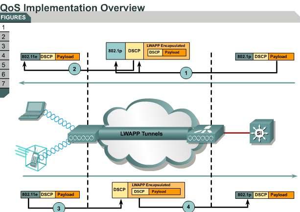
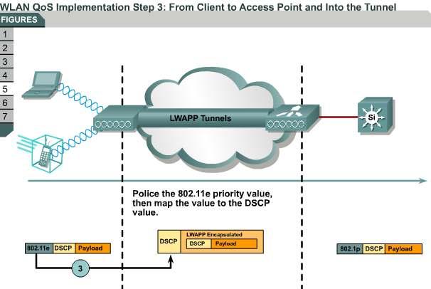
9 6.1.6WLAN QoS Implementation When voice or video uses a WLAN, the service must integrate with the wired network and Voice over IP (VoIP) systems to deliver consistent, high quality end-to-end service. QoS protocols used on the WLAN and wired network media must be mapped to one another while traffic transits the boundary between the two media. In particular, WLAN e packets must be mapped to LAN 802.1p packets and vice versa. Figure [1] provides a brief overview of how to implement QoS on a WLAN. 9
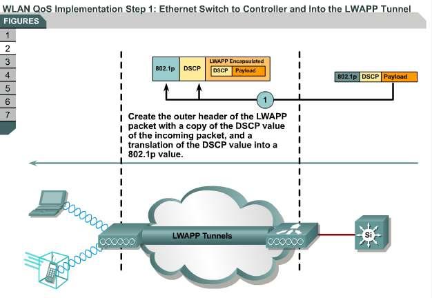
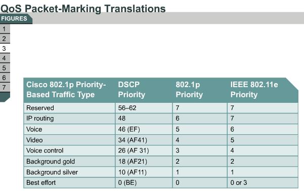
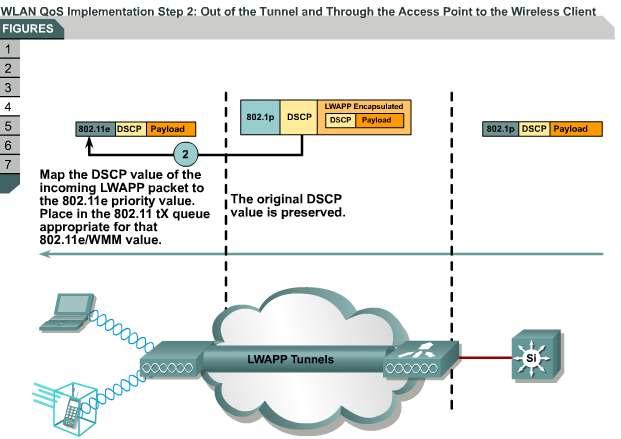
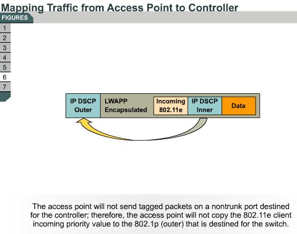
10 When a WLAN client sends e traffic, it will have a User Priority (UP) classification in its frame (802.1p or e). The access point needs to map this e classification into a DSCP value for the LWAPP packet carrying the frame to ensure that the packet is given the appropriate priority on its way to the wireless LAN controller. A similar process needs to occur on the wireless LAN controller for LWAPP packets going to the access point. Also needed is a mechanism to classify traffic on both the access point and the wireless LAN controller for non e clients, so that their LWAPP packets can also be given the appropriate priority. Figure shows how traffic that originated in the wired network passes through a LAN switch to a controller, through LWAPP tunnels to an access point, and then to a wireless client. The bottom of the diagram shows the process from the wireless client to the wired LAN. There are four steps in the process: Step 1 Step 2 Step 3 Step 4 The traffic travels from the Ethernet switch to the controller. The traffic travels from the access point to the wireless client. The traffic travels from the client to the access point. The traffic travels from the controller to the Ethernet switch. This series of subtopics gives details on the steps of QoS implementation: WLAN QoS Implementation Step 1: From Ethernet Switch to Controller and LWAPP Tunnel When a LAN controller forwards an LWAPP packet to an access point, it must contain the QoS information from the original Ethernet packet coming from the Ethernet switch. The WLAN controller puts this information into the outer header in an LWAPP packet. Figure shows how the controller encapsulates the incoming Ethernet packet retaining the original DSCP value and payload. The controller also translates the DSCP value of the incoming packet to the appropriate 802.1p priority value. These values are placed in the outer header of the LWAPP frame. LWAPP control packets are always tagged with an 802.1p value of 7, while the encapsulated LWAPP data packets derive the DSCP and 802.1p value from the original packet. QoS Packet Marking Translations Default mapping between DSCP, 802.1p, and e exist as shown in the table in Figure. The following are notes on Layer 3 QoS packet marking enhancements: Layer 3 QoS is not supported 10
11 11
12 12
13 13

14 6.1.7Packet Tagging There are two situations to consider: tagged and untagged packets. Tagged packets: The 802.1p- or DSCP-tagged packets are received from the LAN: o The tag is propagated to the LWAPP frame. o The WLAN ID-configured QoS takes priority for the assigned access category; if the tag is lower than the configured QoS, the access point queues the packet at a lower access category. o An authentication, authorization, and accounting (AAA) override can be applied to Cisco Identity Based Networking Services (IBNS) WLAN clients. Untagged packets: Untagged packets received from the LAN receive the following treatment: o The WLAN ID-configured QoS is applied for the access category. o An AAA override can be applied to Cisco IBNS WLAN clients. Figure summarizes these points. The e QoS packets received from the WLAN receive this treatment: The tag is propagated to the LWAPP frame. The WLAN ID-configured QoS takes priority for the assigned 802.1p tag; if the e access category is lower than the configured QoS, a lower 802.1p tag will be applied. The e QoS packets received from the WLAN are 802.1p-tagged when they are transmitted on the LAN by the controller. Non-QoS packets that are received from the WLAN will be given best-effort priority (default silver) when they are transmitted on the LAN by the controller. Figure summarizes these points. 14
, moving from individual controllers to a network of controllers.")

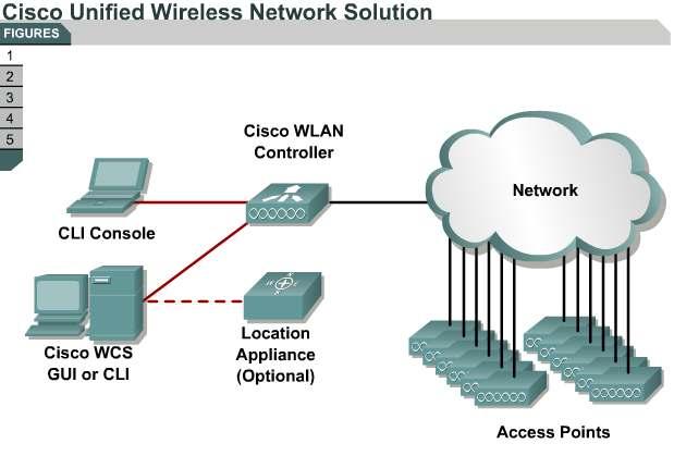
15 Introducing Cisco WCS The Cisco Wireless Control System (WCS) is a Cisco Unified Wireless Network Solution management tool that adds to the capabilities of the web user interface and command line interface (CLI), moving from individual controllers to a network of controllers. WCS includes the same configuration, performance monitoring, security, fault management, and accounting options used at the controller level and adds a graphical view of multiple controllers and managed access points. Figure is a representation of the Cisco Unified Wireless Network Solution of which WCS is an integral part. The WCS user interface enables operators to control all permitted Cisco Unified Wireless Network Solution configuration, monitoring, and control functions through Internet Explorer 6.0 or later. 15
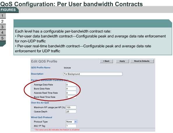
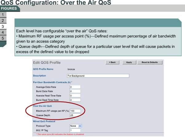
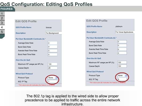
16 Operator permissions are defined by the administrator using the WCS user interface Administration menu that enables the administrator to manage user accounts and schedule periodic maintenance tasks. A later lesson will cover WCS in more detail. This topic uses WCS to configure QoS on the WLAN. QoS-Configurable Profiles By default, the WLAN priority is set by the slot timers that EDCF uses. Figure shows the section of the web page where you can configure a bandwidth contract rate for each of the four access categories. Each bandwidth contract rate is further divided into average and peak rates of User Datagram Protocol (UDP) or non-udp traffic. We recommend using the default bandwidth rate parameters. On the same web page, you can configure the Over the Air QoS settings that control the maximum RF usage from each WMM access category. By default, these settings are all set at 100 percent. The Queue Depth field controls the internal queue depth for each respective access category. The defaults for both parameters are listed in the Over the Air QoS Defaults table. Figure shows where to enter the parameters. Over the Air QoS Defaults Access Category RF Usage Queue Depth Platinum 100 percent 100 Gold 100 percent 75 Silver 100 percent 50 Bronze 100 percent 25 The mapping from 802.1p to WMM access categories can also be specified at a broad, controllerwide level. Figure shows examples of editing bronze and platinum profiles. The only option for the Protocol Type drop-down field is 802.1p. Current (version 3.2) controller codes have the default mappings as listed in the Access Category table. Access Category Access Category 802.1p Priority Platinum 6 Gold 5 Silver 3 Bronze 1 Configuring WLAN IDs for QoS Figure shows how WLAN IDs can be configured individually for QoS on a controller. The general WMM or e policy for wireless client interaction to the access point can be controlled at the WLAN ID of the wireless controller. The three possible values are listed and described in the Configuring WLAN ID Parameters table. Configuring WLAN ID Parameters Parameter Value Disabled Allowed Description The Disabled parameter ignores the WMM or e QoS request. The Allowed parameter offers QoS to WMM- or e-capable wireless clients and default QoS for non-wmm/802.11e wireless clients. 16
17 Required The Required parameter requires all wireless clients to be WMM or e compliant and to use any WLAN ID that this parameter defines. Note The WLAN ID is the association from the WLAN service set identifier (SSID) to a unique internal number, which in turn associates to security policies and the existing Ethernet interface of the controller. 17
18 18
19 19

20 6.2.1The Need for WLAN Security Because WLANs use radio waves, WLANs are open to hackers who try to access sensitive information or disrupt network operations. Hackers can drive past potential targets using wireless sniffing tools to find unprotected networks. This is called war driving. Many corporations, retail operations, offices, and homes are open to intruders. The vulnerability of wireless networks arises from the false belief that the spread spectrum modulation technique of several of the wireless LAN standards (including b) has built-in security. Engineers developed spread spectrum during World War II as a means of preventing enemy jamming of radio communications. Modern WLAN vendors mistakenly assumed that their use of spread spectrum also provided security. In the intended military applications, spread spectrum attempts to provide security by changing the "spreading codes" with a secret key making deciphering the signal without the code nearly impossible. However, the standard describes the spreading codes publicly to provide component interoperability. A hacker only needs an compliant radio network interface card (NIC) to connect to a vulnerable WLAN. Most wireless devices that are sold today are wireless network-ready. End users often do not change the default settings or implement only standard Wired Equivalent Privacy (WEP) security, which is not an optimal solution for secure wireless networks. Figure lists some of the vulnerabilities that arise from WLAN design and the standard. The following subtopics briefly describe WLAN vulnerabilities. SSID The SSID is a network-naming scheme and configurable parameter that both the client and the access point must share. The SSID feature serves to segment logically the users and access points that form part of a wireless subsystem. The standard requires that a user's radio NIC has the same SSID as the access point to enable association and communications. In the absence of optional security features, the SSID is a form of password and is the only "security" mechanism that the access point needs to establish a connection. Most access points broadcast the SSID multiple times per second within the body of each 20
21 beacon frame, so a hacker can easily use an analysis tool to identify the SSID. In fact, Windows XP and Windows Vista sniff for SSIDs and automatically configure the radio NIC in the end user device. This means that even if a user starts with unmatched SSIDs, he or she may well be able to associate with an SSID revealed by the Windows XP scan for available networks. To make the hacker s task even easier, many WLAN deployments use the access point default SSID. If you try your own war driving looking for linksys, you will find out how prevalent this practice is. Even deactivating SSID broadcasting to delete the SSID from the beacon frames will not stop hackers from finding the SSID. Hackers simply need to wait until someone associates or reassociates with the network. MAC Filtering A client that is connecting to an access point must go through the process of authenticating and associating. Some WLANs support filtering using a MAC address. Network administrators construct tables manually on the access point to allow or disallow clients based on their physical hardware address. However, spoofing MAC addresses is an easy hacker task. MAC address filtering is not considered a security feature. Automatic DHCP Most WLANs use DHCP to assign IP addresses. DHCP assigns IP addresses to legitimate users as easily as to hackers. Once connected, the hacker sees everyone else who is connected to the network, as well as shared files or resources. Many people overlook this problem, especially when working at home or on a public network. Cracking WEP Basic WEP security is designed to guard against the threat to network security from unauthorized devices outside the LAN. Under WEP, the network considers any device with a valid WEP key as a legitimate and authorized user. With only basic WEP encryption enabled (or with no encryption enabled), it is possible to collect data and obtain sensitive network information, such as user login information, account numbers, and personal records. WEP encrypts the body of each frame using the RC4 encryption algorithm, which operates by expanding a short key into a pseudo-random key stream. The sender encrypts data with the key and the receiver uses a copy of the same key to decrypt the data. Unfortunately, a hacker can crack any WEP key with readily available software in two minutes or less. If an attacker obtains the WEP key through hardware loss, theft, or a wireless security exploit, the network and wireless users are vulnerable, and keys must be changed. Most WLAN client utilities assign persistent WEP keys (keys that are stored in nonvolatile memory on the card itself) to a client adapter. Basic WEP security provides only one-way authentication. The client is authenticated with the access point (the WEP key is checked), but not vice versa; this is called origin authentication. On the other hand, the client has no way of knowing whether the access point is a legitimate part of the WLAN or a rogue device that uses the same WEP key; this is a concern for man-in-the-middle attacks. A hacker using shared key authentication can capture the challenge text packet that is sent to the client and then capture the encrypted response, thus allowing the hacker to derive the WEP key that is being used: using a WLAN sniffer, a hacker can capture enough packets to crack the security and derive the WEP keys, no matter which method of authentication is being used. Although basic WEP is better than no security, this option is inadequate. Initialization Vector Attack To avoid encrypting two ciphertexts with the same key stream, WEP uses an Initialization 21
22 Vector (IV) to augment the shared secret key and produce a different RC4 key for each packet. The IV is included in the packet. A passive or weak IV is another type of attack. The method of changing the IV depends on the vendor implementation. (Cisco Aironet wireless products change the IV on a per-packet basis.) If the IV is transmitted as plaintext, an attacker who is sniffing the WLAN can see the IV. Using the same IV repeatedly with the same WEP key, a hacker can capture the frames and derive information about the data in the frame and data from the network. Static WEP keys have proven to be highly vulnerable to this type of attack, and that is why static WEP use is discouraged; instead, use more advanced security features discussed later in this lesson. Cisco Aironet access point firmware includes features to improve RC4 and WEP security by hashing WEP keys, thus protecting against weak IVs. You must take care that you configure WLAN security to protect against this type of attack. Configuring the WEP key timeout on the authentication server provides protection. This practice forces wireless clients to reauthenticate, resulting in the generation of a new WEP key. A shorter timeout period means wireless clients do not use the same WEP key long enough for a hacker to capture the number of frames that are needed to deduce the WEP key. Password Cracking Most password-based authentication algorithms are susceptible to online (active) and offline (passive) dictionary attacks. During a dictionary attack, an attacker tries to guess a password and gain network access by using every word in a dictionary of common passwords or possible combinations of passwords. A dictionary attack relies on the fact that a password is often a common word, name, or concatenation of words or names with a minor modification such as a trailing digit or two. Longer passwords with a variety of characters (such as 4yosc10cP!) offer the greatest protection against dictionary attacks. During an online dictionary attack, an attacker tries to gain network access by trying possible combinations of passwords for a specific user. Online dictionary attacks can be prevented using lockout mechanisms that are available on RADIUS servers to lock the user out after a certain number of invalid login attempts. Online attacks also provide some evidence that a breach or compromise is being attempted, allowing you to take corrective measures. An offline dictionary attack is carried out in two phases to uncover a password. In the first phase, the attacker captures the challenge and response messages between the user and the network. In the second phase, the attacker looks for a password match by computing a list of possible challenge response messages (using a precomputed dictionary, usually with the aid of a password-cracking program) and comparing these messages against the captured challenge and response messages. The attacker uses known authentication protocol vulnerabilities to reduce the size of the user password dictionary. A strong password policy and requirement that users periodically change their passwords significantly reduces the potential for a successful offline attack using these tools. Unlike online attacks, offline attacks are not easily detected. Man-in-the-Middle Attacks Hackers can monitor frames on a WLAN using an analyzer and position themselves for a "man-in-the-middle" attack. A hacker views the frames that are sent back and forth between a legitimate user's radio NIC and the access point during the association process. This exchange provides information about the radio card and access point including the IP addresses of both devices, association ID for the radio NIC, and SSID. The hacker can then set up a rogue access point (on a different radio channel) closer to a particular user and force the user's radio NIC to reassociate with the rogue access point. Remember that because 22
23 the standard does not authenticate at the access point, the radio NIC will reassociate with the stronger signal of the rogue access point. The hacker can now capture traffic from unsuspecting users who are attempting to log in to their own services. If a rogue access point is programmed with the correct WEP key, client data can be captured. The access point can also be configured to provide unauthorized users with information about the network, such as MAC addresses of clients (both wireless and wired), the ability to capture and spoof data packets, and, at worst, access to servers and files. DoS Attack An attacker can insert bogus packets into the wireless LAN to deny services to users. An attacker can launch a brute force DoS attack with a high power signal generator to produce enough RF interference to jam radio NICs. The inherent design of the standard causes the NIC to stop broadcasting when the NIC senses other RF activity. Another DoS attack fools valid radio NICs with fake frames. By setting up a radio NIC or frame generator to send a continuous stream of clear-to-send frames, the attacker mimics an access point by telling one radio NIC to transmit and all other NICs to wait. The hacker can further use a fictitious user s radio NIC and delay service to everyone else. Security Methods Authentication and Encryption The two primary facilities for securing the WLAN are authentication and encryption. Authentication is a process that requires a user to present some form of identifying credentials to be permitted access to a resource. Encryption is the mechanism that is used to protect the data that flows over the actual data pathway. A common example of encryption is Triple Data Encryption Standard (3DES), which is used in many Cisco System wired network environments. Typically, a data connection between two devices is encrypted after the user is authenticated and authorized to use the resource. Current security standards require that both authentication and encryption be used to protect client devices from having their data intercepted and to protect the network from unauthorized clients attempting to access internal data files. 23

24 WEP Figure shows how WLAN security has evolved. When WLAN security was first introduced, devices supported WEP encryption only. This nonscalable solution used static breakable keys that use weak authentication. Responding to customer requests, Cisco enhanced wireless security by introducing Lightweight Extensible Authentication Protocol (LEAP). LEAP is a Cisco proprietary wireless encryption technique that offers dynamic WEP keys and mutual authentication (between a wireless client and a RADIUS server). LEAP allows clients to reauthenticate frequently. LEAP made WLANs more secure, but the encryption was not strong enough. New attacks proved that improvements were required. An interim solution called Wi-Fi Protected Access (WPA) provides standardized improved encryption and stronger user-based authentication (Protected EAP [PEAP], Extensible Authentication Protocol [EAP], and EAP-Flexible Authentication via Fast Tunneling [FAST]). The interim solution WPA evolved into WPA2, which provides stronger encryption through Advanced Encryption Standard (AES). WPA2 includes 802.1x authentication as well as dynamic key management. WPA2 additionally includes a wireless intrusion detection system (IDS), which identifies and protects against attacks, including DoS attacks. Cisco delivers intrusion prevention system (IPS) capability for Cisco access points to serve as sensors that provide rich RF data to an IPS server. WEP While the bulk of this lesson focuses on LEAP and WPA2, it is worthwhile to begin with a review of WEP: The standard defines a type of security in which 64-bit WEP specifies a shared 24
25 secret key to encrypt and decrypt the data. Originally, WEP used a 40-bit key, which is concatenated with a 24-bit Initialization Vector (IV) to form the RC4 traffic key. U.S. Government export restrictions on cryptographic technology initially limited the key size. Once the government lifted the key size restrictions, most major manufacturers implemented an extended 128-bit WEP protocol using a 104-bit key size. Cisco Aironet 128-bit devices support both 40-bit and 128-bit encryption. Once the WEP key is revealed, a hacker may transform the cipher text into its original form and understand the meaning of the data. Based on the understanding of the algorithm, a hacker may use the cracked WEP key to modify the cipher text and forward the changed message to the receiver. WEP uses a wireless client and access point sharing static WEP keys. This key is checked during the authentication process. If the client WEP key does not match the access point WEP key, the client is not allowed to associate and is unable to connect to the network. Unfortunately, there are no mechanisms to renew the stored WEP key. WEP uses the RC4 algorithm, a stream cipher with known vulnerabilities. Both the encrypting and decrypting endpoints must share the key. Neither key distribution nor key negotiation is mentioned in the standard. Note that WEP keys can be referenced as 40- or 64-bit and 104- or 128-bit, depending on whether the IV of 24 bits is included. Cisco Aironet security features overcome some of these weaknesses using a more secure key derivation technique and by assigning dynamic WEP keys: Secure key derivation: Using the original shared secret secure key derivation is used to construct responses to the mutual challenges. It undergoes irreversible oneway hashes that make password-replay attacks impossible. The hash values sent over the wire are useful for one-time use only at the start of the authentication process, and therefore, never after. Dynamic WEP keys: Using Cisco Aironet security features means that each wireless client can be granted a new, dynamic WEP key each time the client accesses the network. Because these keys are dynamic and session-based, an intruder cannot learn the system WEP keys and then use them to access the WLAN. WEP keys that are administered in this fashion are referred to as session keys. Each user has a unique WEP key. The access point has all the WEP keys for each associated client, allowing the access point to communicate with each client. Other users who receive information are unable to decrypt the information. Figure lists key points that concern WEP. 25


26 6.2.3WLAN Authentication The standard defines two types of authentication: open and shared key. This topic examines both of these types and the process that the client undergoes during the 26
27 authentication and association process Open Authentication The open authentication method shown in Figure allows authorization and associations with or without a WEP key. If the client does not use a WEP key, the client undergoes the normal authentication without any kind of key or password, followed by association with the access point. The user is then granted access to the network. This method is the standard method for public hot spot areas that offer Internet access. If a WEP key is used, the client goes through the normal authentication and association process. When the client is associated and data transmission begins, a client using a WEP key encrypts the data. If the WEP key on the access point does not match, then the access point is unable to decrypt the data, so it is impossible to send the data via the WLAN. Note that the header is not encrypted; only the payload (or data) is encrypted Shared Key Authentication The example shown in Figure shows the wireless client using shared key authentication to attempt to associate with an access point. Steps 1 through 3 are the same as those for the open authentication process shown in Figure. There are three more steps as follows: Step 4 Step 5 Step 6 Access point A sends an authentication response. The access point sends the authentication response that contains challenge text to the client. This packet is unencrypted. The client then uses the text from the authentication response to form another authentication packet, which is encrypted using one of the client WEP keys, and sends this as a response to the access point. Access point A then compares the encrypted challenge text against the access point copy of the encrypted challenge text. If the encrypted text is the same, then the access point allows the client on the WLAN. Shared key authentication is considered less secure than open authentication because of the challenge text packet. Because this packet is sent unencrypted and then returned as an encrypted packet, it may be possible to capture both packets and determine the stream cipher. 27


28 6.2.4Cisco Enhanced WEP Security Starting in 2001 and continuing into 2002, Cisco introduced a prestandard form of enhanced security that incorporates two elements to improve standard or basic security. Improved authentication and encryption enhance security to check user credentials before granting access and increase the security integrity of the user session after association to the 28
29 network. Encryption for is enhanced with multiple mechanisms to aid in protecting the system from malicious exploits against the WEP key as well as to protect the investment in the system by facilitating encryption improvements in existing hardware. Cisco Key Integrity Protocol (CKIP) protects the WEP key from exploits that seek to derive the key using packet comparison. Cisco Message Integrity Check (CMIC) is a mechanism for protecting the wireless system from inductive attacks, which seek to induce the system to send either key data or a predictable response that can be analyzed (compared to known data) to derive the WEP key. Cisco clients and compatible clients can use CKIP and CMIC with 802.1x authentication or with static WEP keys when communicating to Cisco autonomous access points. Figure summarizes these points. Enhanced Security Enhanced security through either WPA or WPA2 (802.11i) incorporates authentication and encryption to improve upon basic security. Authentication and encryption check user credentials before access is granted and to increase the security integrity of the user session after association to the network. Authentication in leverages the IEEE 802.1x standard to authenticate users and to permit policy assignment to those users based on the authentication transaction. Basing the authentication transaction on user rather than machine credentials reduces the risk of security compromise from lost or stolen equipment. The 802.1x authentication also permits flexible credentials to be used for client authentication. Passwords, one-time tokens, PKI certificates, or device IDs can be used for authentication. Using 802.1x for wireless client authentication also has the advantage of allowing dynamic encryption keys to be distributed to each user each time that the user authenticates to the network. Encryption for is enhanced with multiple mechanisms to aid in protecting the system from malicious exploits against the WEP key as well as in protecting the investment in the system by facilitating encryption improvements in existing hardware. Figure summarizes these points. Encryption TKIP and MIC The first enhancements to the b WEP standard fall under the umbrella of Temporal Key Integrity Protocol (TKIP pronounced tee-kip ). TKIP contains several key enhancements to RC4-based WEP: key hashing or perpacket keying, message integrity check (MIC), and broadcast key rotation. TKIP protects the WEP key from exploits that seek to derive the key using packet comparison. Cisco Key Integrity Protocol (CKIP) protects the WEP key from exploits that seek to derive the key using packet comparison. MIC is a mechanism for protecting the wireless system from inductive attacks, which seek to induce the system to send either key data or a predictable response that can be analyzed to derive the WEP key. The MIC is an additional 8-byte field placed between the data portion of an (Wi-Fi) frame and the 4-byte Integrity Check Value (ICV). The MIC has a function very similar to the older ICV. However, the ICV only protects the packet payload. The MIC protects both the payload and the header. The algorithm that implements the MIC is known as Michael. Michael also implements a frame counter, which discourages replay attacks. The Cisco proprietary mechanism is referred to as CMIC (Cisco Message Integrity Check). TKIP and MIC are both elements of the WPA standard intended to secure a system against all 29
30 known WEP key vulnerabilities. Note Current Cisco equipment supports CKIP and CMIC and the Wi-Fi WPA and WPA2 standards. Different algorithms are used in CKIP and TKIP, making them incompatible between a wireless client and access point. Both the access point and the client must use the same protocol. Although access points can be configured to support both security protocols in a mixed environment, we always recommend that you use TKIP. Figure summarizes these points. WPA and WPA2 WPA was a WiFi Alliance interim solution. WPA2, ratified in June 2004 as IEEE i, encompasses the prior WPA features plus a number of security improvements. WPA resolves the issue of weak WEP headers (IV) and provides a way to ensure message integrity using TKIP to enhance data encryption. WPA provided a solution for security problems that were known up to and including These problems include the well-publicized AirSnort and man-in-the-middle WLAN attacks. AirSnort is a wireless LAN (WLAN) tool that recovers encryption keys. AirSnort operates by passively monitoring transmissions, computing the encryption key when it gathers enough packets. WPA2 overcomes some of the weaknesses in WPA. WPA2 uses the AES algorithm. AES is a stronger security algorithm than the RC4 stream cipher used by WPA, but AES is more processor-intensive. Hardware updates are required to move to AES encryption while maintaining comparable throughput. The WPA mechanisms were designed to be implemented by vendors in current hardware, meaning that users should be able to implement WPA on their current systems with only a firmware or software modification. Figure summarizes these WPA2 elements: A mechanism for authenticated key management: the user is first authenticated, and then a master key is derived at the server and client. This master key is used to generate the actual keys that are used in encrypting the user session. The master key is not directly used. Key validation mechanisms are in place for both unicast and broadcast keys. TKIP is used, which for WPA includes both per-packet keying and MIC. The IV is expanded from 24 to 48 bits. This expansion prevents collisions or reuse of the same vector, which can be used in exploits to attempt to derive an encryption key. IV collisions are one of the primary mechanisms that tools such as AirSnort use. Broadcast key rotation is usually used with server-based authentication, and the result is the key. This key is changed quickly enough that attackers cannot accept enough packets to obtain the key. Encryption AES AES replaces RC4 as the encryption mechanism in the IEEE i specification (or WPA2). The protocol is called Advanced Encryption Standard-Cipher Block Chaining Message Authentication Code Protocol (AES-CCMP). AES is the next-generation encryption function that the U.S. National Institute of Standards and Technology (NIST) approved. NIST solicited the cryptography community for new encryption algorithms. The algorithms that NIST considered had to be fully disclosed and available royalty free. NIST judged candidates on cryptographic strength as well as practical implementation. The finalist, and the adopted method, is known as the Rijndael algorithm. AES uses a 128-bit block cipher and requires newer or current radio cards on both access points and clients to eliminate throughput reduction that stems from an increase in 30


31 computational load for encryption and decryption. If you are planning to implement AES on existing equipment, check Cisco.com documentation to verify whether your current hardware supports AES or whether you need to upgrade. AES-CCMP uses IVs to augment the key stream. The IV value increases by one after encrypting each block. This technique provides a unique key stream for each block. AES- CCMP also uses a message authentication check to verify packet integrity using frame length, destination and source addresses, and data in input values. Figure summarizes these points. 31


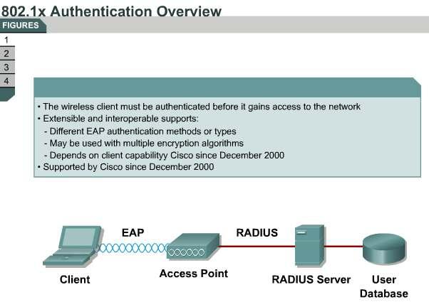
32 x Overview The IEEE developed a supplement to the IEEE 802.1d standard to define the changes that are necessary to the operation of a MAC-layer bridge to provide port-based network access control capability. This is called the 802.1x standard. WLAN 802.1x has the following features, summarized in Figure : RADIUS and EAP encapsulate EAP packets within RADIUS. 32
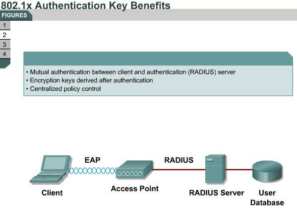
33 Supports multiple EAP types. Bases identification on the network access identifier (NAI). The standard supports roaming access in public spaces. Supports RADIUS for centralized AAA (RFC 2903). This standard can be used with multiple encryption algorithms: o AES o WPA TKIP o WEP WEP keys are dynamic instead of static and do not require user intervention-based management. This standard is compatible with existing roaming technologies, enabling use in hotels and public places x Authentication Key Benefits A major advantage of EAP and the 802.1x standard is that their design leverages existing standards. With support for EAP, WLANs can now offer these features, listed in Figure : Support for RFC 2284, with password authentication: Users are authenticated based on a username and password that are typically already stored in an active directory on the network. This directory is in turn connected to a certificate server, such as a RADIUS server or the Cisco Secure Access Control Server (ACS). RFC 2284 allows for various token card implementations that require user input by using a Generic Token Card (GTC) type. The request contains an ASCII text message and the reply contains the token card information necessary for authentication. Typically, this would be information read by a user from the token card device and entered as ASCII text. One-time password (OTP): OTP encrypts a plaintext password. Thus, plaintext passwords never have to be typed on an insecure connection (Telnet and FTP use no encryption and therefore are not considered secure protocols). EAP support allows additional authentication methods to be deployed with no changes to the access point or client network interface card (NIC). Nothing beyond the latest versions of firmware and drivers are required for Cisco Aironet equipment to take advantage of the benefits that EAP offers. The wireless authentication protocols do require client software to participate in the authentication process. This software, as well as the device running the software, is commonly referred to as a supplicant. With all 802.1x authentication types, dynamic encryption key distribution can be supported. Dynamic keying, and the ability to manage the user database centrally, is a major advantage of 802.1x and EAP x and EAP Authentication Protocols The 802.1x specification requires mutual authentication of the client and server device. This process can be accomplished through various mechanisms listed in Figure : LEAP is an 802.1x-compliant authentication mechanism that Cisco Systems developed and that is available on both Cisco NICs and NICs from other vendors. EAP FAST is a client-server security architecture that encrypts EAP transactions with a Transport Layer Security (TLS) tunnel. Although similar to PEAP in this respect, this protocol differs significantly in that, EAP-FAST tunnel establishment is based on a strong secret called the protected access credential (PAC), which is unique to users. EAP-TLS uses certificates to authenticate both the server (network) and client. EAP-GTC (Generic Token Card) was created by Cisco as an alternative to PEAPv0/EAP-MSCHAPv2. It allows the use of an inner authentication protocol other than Microsoft Challenge Handshake Authentication Protocol version 2 (MSCHAPv2). EAP-GTC carries a text challenge from the authentication server, and a reply that is 33
34 assumed to be generated by a security token. EAP-GTC does not protect the authentication data in any way. PEAP is a protected authentication mechanism that uses a certificate to encrypt the authentication exchange between the client and the EAP server. The authentication exchange can be either GTC or MSCHAPv2. Components Required for 802.1x Authentication Figure shows the components that a system needs for 802.1x authentication. An authentication server is required for 802.1x x uses a RADIUS server to authenticate clients to the network. An authenticator can be a device such as a switch or an access point. This device operates on the enterprise edge, meaning that the device is the interface between the enterprise network and the public or semipublic network, where security is most needed. The client device contains a supplicant. The supplicant sends authentication credentials to the authenticator, and the authenticator then sends the information to the authentication server. At the authentication server, the login request is compared to a user database to determine whether and at what level the user is granted access to network resources. 34
35 35

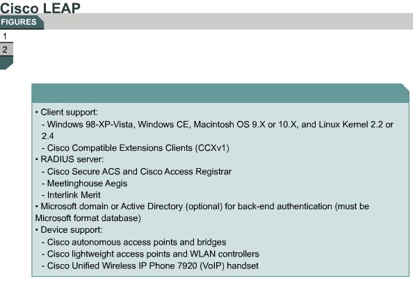
36 6.2.6LEAP LEAP provides some unique capabilities that may be difficult to duplicate with other authentication schemes, as summarized in Figure : Fast, secure roaming with Cisco clients or compatible clients A broad range of operating systems and devices, including Macintosh, Linux, and DOS 36
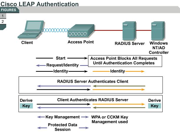
37 Single login to a Microsoft Active Directory or Windows NT domain using Microsoft credentials If a Microsoft database is used, and if it is desirable to use native operating system authentication support, it may be possible to use Microsoft PEAP (PEAP [EAP-MSCHAPv2]) or EAP-TLS. Single login is supported with these solutions. Several RADIUS servers support Cisco LEAP, including Cisco Secure Access Control Server (ACS) and Cisco Access Registrar, Meetinghouse Aegis, and Interlink Merit. Cisco LEAP Authentication As you can see from Figure, the authentication process requires three components, shown at the top of the figure: the client, or supplicant; the access point, or authenticator; and the RADIUS server (in 802.1x terminology, the authentication server). The authentication can start in one of two ways: by client initiation with the Start message or by access point initiation with the Request/Identity message. In either case, the client responds to the access point with a user name. The access point encapsulates that response in a RADIUS Access-Request message and forwards the response to the RADIUS server. The RADIUS server then begins the challenge response process with the client. After the challenges are met with correct authentication, a Success message is sent to the access point, indicating that the client has been authenticated. The client needs to validate that the access point and RADIUS server are truly what they say they are. This process is the LEAP mutual authentication function. The client sends a challenge message to the access point to forward to the RADIUS server. The RADIUS server must then correctly respond to the challenge for the client to validate the network and then associate. Upon successful authentication, a pairwise master key (PMK) is generated on both the client and the RADIUS server. The RADIUS server forwards the PMK for installation in the access point for that specific client. The access point and the client perform the four-way handshake. 37
38 6.2.7EAP-FAST 38
39 EAP-FAST consists of an optional Phase 0, followed by Phases 1 and 2: Phase 0: Unique to EAP-FAST, Phase 0 is a tunnel-secured means of providing an EAP-FAST end-user client with a protected access credential (PAC) for the user requesting network access. Phase 0 is optional, and PACs can be manually provided to end-user clients. A PAC is a digital credential that is distributed to users for network authentication. A PAC always consists of a secret part and an opaque part. The secret part is secret key material that can be used in future transactions. The opaque part is presented when the client wants to obtain access to network resources. The opaque part aids the server in determining whether the client possesses the secret part. Each PAC has a specific user ID and an authority ID associated with the PAC. Phase 1: In Phase 1, the RADIUS server and the end user-client use the PAC to authenticate each other and establish a secure tunnel. Like PEAP, EAP-FAST uses TLS to verify the identity of the AAA server and establish a secure tunnel between the client and the AAA server. The PAC replaces the digital certificate that PEAP uses and eliminates the need for a public-key infrastructure (PKI) to manage the certificates. Phase 2: In Phase 2, the RADIUS server authenticates the user credentials with EAP- GTC, which is protected by the TLS tunnel that is created in Phase 1. EAP-FAST Authentication Figure illustrates how the wireless client associates with an access point using open authentication: The access point restricts all traffic from the client until the client has authenticated to the RADIUS server. The client sends an EAP over LAN (EAPOL)-start frame to the access point. The access point returns a Request/Identity to the client. The client sends a network access identifier (NAI) format address to the access point, which passes the NAI to the RADIUS server. The server and the client mutually authenticate each other using Phase 1 and Phase 2 of the EAP-FAST process. The RADIUS server sends the session key to the access point in a Success packet. The RADIUS server and client negotiate and derive the session encryption key. This process varies based on whether the client is using WEP or IEEE i. The client and the access point use the keys during the session. At the end of the session, the client sends an EAPOL-logout packet, and the access point returns to the preauthentication state (filtering all but EAPOL traffic) 39
 encryption mechanism.")
40 6.2.8EAP-TLS EAP-TLS is one of the original authentication methods that the IEEE specified when 802.1x and EAP were initially proposed and established as a standard. TLS is used in many environments and is intended to be an alternative, standardized version of the widely deployed Secure Sockets Layer (SSL) encryption mechanism. 40
41 EAP-TLS uses a message authentication code that is derived from a certificate to authenticate a user. Certificates are issued to users and computers by a certificate authority (CA) and are used to validate identity. The maintenance of the CA (which is part of a PKI) can be a barrier to EAP-TLS deployment for some customers. All clients (users) must have their own certificates personally issued and installed on their machines in order to perform TLS authentication. Each AAA server must also have unique certificates. EAP-TLS has native support on Microsoft Windows 2000, Windows XP, Windows CE, and Windows Vista. Third-party supplicants can be used for non-windows support. Meetinghouse has supplicant software that supports EAP-TLS. With the Cisco (and Microsoft) implementation of EAP-TLS, it is possible to tie the Microsoft credentials of the user with the certificate of that user in a Microsoft database, which permits one-time sign-on to a Microsoft domain. EAP-TLS Authentication Figure illustrates the 802.1x EAP authentication process with EAP-TLS as the authentication protocol. The process takes part in many steps: The wireless client associates with the access point using open authentication. The access point restricts all traffic from the client until the client has authenticated to the RADIUS server. The client sends an EAPOL-start frame to the access point. The access point returns a Request/Identity to the client. The client sends an NAI ( format) address to the access point, which passes the address on to the RADIUS server. The server and the client mutually authenticate each other using an exchange of digital certificates. The RADIUS server sends the session key to the access point in a Success packet. The RADIUS server and client negotiate and derive the session encryption key. This process varies based on whether the client is using WEP or i. The client and the access point use the keys during the session. At the end of the session, the client sends an EAPOL-logout packet, and the access point returns to the preauthentication state (filtering all but EAPOL traffic). 41


42 6.2.9PEAP PEAP is an authentication protocol that was jointly proposed and developed by Cisco, Microsoft, and RSA Security. The purpose of PEAP is to protect the authentication transaction with a TLS-secured connection, much as you might secure a connection to an e-commerce website when performing an online transaction. 42
43 Note that there are two implementations of PEAP: PEAP-GTC PEAP-Microsoft Challenge Handshake Authentication Protocol version 2 (MSCHAPv2) The PEAP-GTC authentication mechanism allows generic authentication to a number of databases Novell Directory Service (NDS), Lightweight Directory Access Protocol (LDAP), OTP, and so on. The PEAP-MSCHAPv2 authentication mechanism allows authentication to databases that support the MSCHAPv2 format, including Microsoft NT and Microsoft Active Directory. As with other 802.1x and EAP types, dynamic encryption can be used with PEAP. A CA certificate must be used at each client to authenticate the server to each client before the client submits authentication credentials. Figure summarizes and expands on these points. EAP-PEAP Authentication Figure illustrates the 802.1x EAP authentication process with EAP-PEAP as the authentication protocol, a multistep exchange: The wireless client associates with the access point using open authentication. The access point restricts all traffic from the client until the client has authenticated to the RADIUS server. The initial handshake between the client and the access point is a TLS handshake, as seen earlier. The client authenticates the server using a CA to verify the digital certificate of the server. Then the client and the server establish an encrypted tunnel. The client submits client credentials inside the tunnel using either MSCHAPv2 or GTC. The RADIUS server sends the session key to the access point in a Success packet. The RADIUS server and client negotiate and derive the session encryption key. This process varies based on whether the client is using WEP or i. The client and the access point use the keys during the session. At the end of the session, the client sends an EAPOL-logout packet, and the access point returns to the preauthentication state (filtering all but EAPOL traffic). 43

44 6.2.10Wi-Fi Protected Access WPA Characteristics WPA is the Wi-Fi Alliance standards-based mechanism that creates secure and interoperable 44
45 WLAN networks. WPA provides a mechanism to authenticate keys for use in environments as well as providing enhancements to WEP encryption to increase the robustness of the security protocol. WPA was an interim solution proposed by the wireless industry consortium to create a WLAN standard in advance of the IEEE standard for security, IEEE i, which was ratified in June WPA addressed vulnerabilities of standard WEP security and permitted a path for migration of users to this new security mechanism through a software upgrade. Components of WPA WPA is a standard that describes a combination of security capabilities. These capabilities were available before WPA became an industry standard (note that WPA was not an IEEE standard as of late 2003), but WPA pulls the capabilities into one definition. The following, listed in Figure, are the most important aspects of WPA: Authenticated key management: Either using 802.1x authentication or a preshared key, the user is authenticated prior to authentication of the keys that are used. Unicast and broadcast key management: The keys that are derived after user authentication are authenticated through a handshake process between the access point and client. TKIP (per-packet keying) and MIC. IV space expansion: The IV space is expanded from 24 bits, as in WEP, to 48 bits in WPA. WPA Migration Mode: Cisco defines WPA Migration Mode as an access point setting to enable both WPA and non-wpa clients to associate to an access point using the same SSID i or WPA Authentication and Key Management Overview Figure provides an overview of i or WPA Authentication and Key management. Initial authentication using WPA is essentially identical to standard authentication and association. The primary difference in WPA is in the initial association request (probe request) that the client and access point send. The client and access point must agree to a security capability during association. After initial association and exchange of security capabilities, the client and authentication servers proceed with standard 802.1x authentication. After successful authentication, the server derives and distributes a master key to the access point. The same master key is derived at the client. With these master keys, the access point and the client perform a four-way handshake to validate the access point, and the client validates the group or broadcast key using a two-way handshake. Unicast Keys: Four-Way Handshake Before the WPA handshake can occur, the pairwise master key (PMK), a 256-bit key, is generated because of the 802.1x authentication process between the client and the authentication server, or the process uses the 64-hexadecimal character preshared key (or a key stream derived from the preshared key phrase). Figure shows the four-way handshake process: 45
46 Step 1 Step 2 Step 3 Step 4 The access point sends a nonce or random number to the client. The client responds to the access point with the client s own nonce or random number, along with the WPA information element, pairwise transient key (PTK), and MIC key information. The access point sends the nonce again, along with the information element, PTK, MIC key information, and install message. The resending of this information validates that the client and access point share common authentication information. The client sends MIC key information and the PTK to the access point for acknowledgment. Note A pseudorandom function (PRF) is used to compute the PTK as a function of client and access point random numbers and the MAC addresses of the access point and client. Group Key Handshake The group master key (GMK) is either generated using a random number function or is initialized by the first PTK that the access point uses. When the access point has the GMK, a group random number is generated. This random number is used to derive a group transient key (GTK). Inputs are a PRF that uses the random number and the access point address. The GTK is used to provide a group key as well as MIC keys, which can be used to verify the integrity of the key data. WPA Key Management Phases As part of WPA compliance, an access point must be capable of advertising security capabilities in the access point s beacons. This process describes the unicast, multicast, and authentication types that are supported. From the capabilities advertised by the access point, the client selects the best supported security type for the client authentication. After the client has determined an authentication type, the client proceeds with open authentication using either 802.1x to a RADIUS server or using a preshared key between the access point and the client. This process has the advantage of mutual authentication of client and server as well as providing a centralized resource for client admission control. Upon completing standard 802.1x or EAP messaging between the client and server, a master key is independently generated at the server and client. This master key is then used to derive a PTK that is used in the authentication of the encryption key components that the access point and the client use between each other. 46
 that WPA uses is an enhancement to the basic security mechanism that 802.11 WEP (RC4 encryption) defines.")
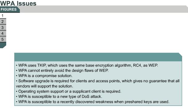
47 6.2.11WPA Issues WPA is an updated security option that was intended to address attacks on static WEP keys, but the WPA solution also has some problems. The Temporal Key Integrity Protocol (TKIP) that WPA uses is an enhancement to the basic security mechanism that WEP (RC4 encryption) defines. Note that TKIP is a wrapper 47
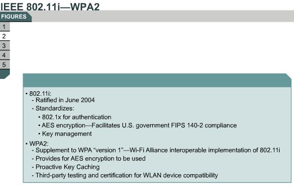
48 around the WEP and RC4 encryption mechanism. WPA relies on RC4 instead of 3DES, AES, or another encryption algorithm. WPA requires access point firmware support there is no guarantee that all wireless access point manufacturers will release firmware upgrades for older models to allow the models to support WPA. WPA requires software driver support for wireless cards there is no guarantee that all wireless card manufacturers will release software driver upgrades for older models to allow older models to support WPA. WPA requires operating system support or a supplicant client the WPA security mechanisms rely on 802.1x or EAP support directly in the operating system or via a supplicant client such as the Funk Software Odyssey Client. Moving to WPA is sometimes an all-or-nothing proposition. Some vendors may not allow mixing WEP and WPA devices. Note that the Wi-Fi Alliance does not recommend mixing WEP and WPA. Mixing is sometimes not actually possible because some vendors have no intention of releasing WPA software upgrade patches for older wireless hardware (some vendors would prefer to sell newer wireless gear with WPA support). This means that some organizations that want to deploy WPA may have to replace a significant amount of their wireless infrastructure. EAP deployment can be a significant undertaking, given that there are so many variants (EAP- Message Digest 5 [EAP-MD5], EAP-TLS, EAP-Tunneled TLS [EAP-TTLS], PEAP, LEAP, EAP-Subscriber Identity Module [EAP-SIM], EAP-Flexible Authentication via Secure Tunneling [EAP-FAST] and so on), each with individual shortcomings and installation issues. EAP also requires the use of an external RADIUS server to authenticate the incoming wireless user connection attempts. Because each manufacturer may offer different EAP methods in the firmware and driver software, customers may not be able to use existing wireless equipment and will be forced to purchase new equipment that supports the chosen EAP method. To maintain backward hardware compatibility, MIC was designed to incur very little computational overhead. As a result, MIC offers only 20 bits of effective security. WPA is susceptible to a new type of DoS attack based on countermeasure techniques that MIC employs. If an access point that runs WPA receives two packets in quick succession with bad MICs, the access point shuts down the entire basic service set (BSS) for one minute. WPA is susceptible to a recently discovered weakness when preshared keys are used instead of i or EAP; the use of a small, noncomplex passphrase can allow an attacker to perform a dictionary attack on captured traffic and recover the passphrase. These issues, summarized in Figure 3, led to the i standard, which was ratified in June 2004 and added three features: 802.1x for authentication AES for encryption Key management The Wi-Fi Alliance WPA2 standard provides third-party testing and certification that WLAN devices must pass. WPA2 Overview WPA2 is a new security standard that the IEEE i task group developed. The Robust Security Network (RSN) specification is the IEEE equivalent of WPA2. WPA2 supports TKIP and generally uses AES block ciphers with Cipher Block Chaining Message Authentication 48
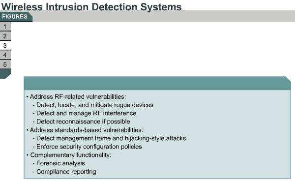
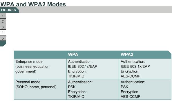
49 Code Protocol (CCMP) for encryption: Generally uses 802.1x authentication methods supports preshared keys Comparable to WPA the same authentication architecture, key distribution, and key renewal Supports Proactive Key Caching (PKC) and preauthentication Intrusion detection system (IDS) added to identify and protect against attacks The i and WPA2 standards are summarized in Figure. Wireless IDSs Figure summarizes the characteristics of wireless IDS. Traditional wired IDSs focus on Layer 3 and higher, but the nature of the RF medium and wireless standards mandate IDS at the physical and data link layers. The RF medium has several vulnerabilities, such as the unlicensed spectrum, which is subject to interference and is not contained by physical security boundaries. Standard vulnerabilities include unauthenticated management frames, session hijacking, and replay-type attacks. IDS protection includes rogue detection and location mapping, IDS attack signatures, client exclusion and containment, and high-resolution location tracking. Cisco offers wireless intrusion prevention system (IPS) options based on the architecture selection: WLAN controller-based Autonomous access point Autonomous access point with partner integration WPA and WPA2 Modes WPA has two modes: Enterprise and Personal. Both modes provide encryption support and user authentication. WPA provides authentication support using IEEE 802.1x and preshared keys (IEEE 802.1x is recommended for enterprise deployments). WPA also provides encryption support using TKIP. TKIP includes MIC and per-packet keying via IV hashing and broadcast key rotation. WPA2 authentication is identical to WPA authentication except that the encryption WPA2 uses is AES-CCMP. Figure 4 shows a table comparing the two WPA2 modes: Enterprise mode: Enterprise mode refers to products that are tested to be interoperable in both the preshared key and IEEE 802.1x or EAP modes of operation for authentication. When IEEE 802.1x is used, a AAA server (the RADIUS protocol for authentication and key management and centralized management of user credentials) is required. Enterprise mode is targeted to enterprise environments. Personal mode: Personal mode is a term given to products tested to be interoperable in the preshared key-only mode of operation for authentication. This mode requires manual configuration of a preshared key on the access point and clients. A preshared key authenticates users via a password, or identifying code, on both the client station and the access point. No authentication server is needed. Personal mode is targeted to small office-home office (SOHO) environments. WPA2 Issues WPA2 solved the remaining security issues of WPA. Because AES is used for encryption, 49
50 more computing power is required, and the hardware must be changed to support WPA2. The client (supplicant) must have a WPA2 driver that supports EAP. This standard is not prevalent and can be a limitation. The RADIUS server must also understand EAP. Although many RADIUS servers support EAP, not all of them do. PEAP carries EAP types within a TLS-secured channel. When TLS is used, a server certificate is used. This feature allows dynamic keys. Compared to WPA, WPA2 is CPU-intensive. More computing power is required for AES encryption support, requiring hardware upgrades rather than a firmware upgrade only. Some older access points will never support WPA2 because hardware upgrades are not available. New equipment is WPA-ready, and only a software upgrade is required. Figure 5 summarizes these points 50
51 51
52 52

53 6.3.1Cisco Unified Wireless Network Business Drivers The modern business climate requires anywhere, anytime connectivity. A worldwide revolution is occurring in business. Mobile users, traveling executives, wireless applications, and advanced services such as VoIP over Wi Fi are driving WLAN expansion and adoption. Mobility changes the way that organizations conduct business. Network managers need to protect their networks and deliver secure WLAN access for their organizations. These managers need a wireless infrastructure that embraces the unique attributes of RF technology and effectively supports today s business applications. They need to keep their wired network secure while laying a foundation for the smooth integration of new applications that embrace wireless technology. Network managers need a WLAN solution that takes full advantage of existing tools, knowledge, and network resources to cost-effectively address critical WLAN security, deployment, and control issues. The Cisco WLAN solution consists of Cisco Wireless LAN Controllers and their associated lightweight access points that are controlled by the operating system, all concurrently managed by the operating system user interface. This lesson presents these elements as listed in Figure. The Cisco Unified Wireless Network is an end-to-end unified wired and wireless network that cost-effectively addresses WLAN security, deployment, management, and control issues. Cisco s unique approach addresses all layers of the WLAN network, from client devices and access points to the network infrastructure, network management, and the delivery of advanced wireless services. As shown in Figure, the Cisco Unified Wireless Network is composed of five interconnected elements that work together as building blocks to deliver a unified enterprise-class wireless solution. Client devices: Cisco is leading the development of interoperable, standards-based client devices through the Cisco Compatible Extensions program. This program helps to ensure the widespread availability of client devices from a variety of suppliers that are interoperable with a Cisco WLAN infrastructure. Cisco Compatible Extensions client devices deliver out of the box wireless mobility, quality of service (QoS), network management, and enhanced security. Mobility platform: Cisco Aironet lightweight access points provide ubiquitous network 53
54 access for a variety of indoor and outdoor wireless environments, including wireless mesh. The Cisco solution supports a wide array of deployment options, such as single or dual radios, integrated or remote antennas, and rugged metal enclosures. These solutions operate as plug-and-play wireless devices with zero-touch configuration. Network unification: The Cisco Unified Wireless Network includes a solid migration path into all major Cisco switching and routing platforms through Cisco Wireless LAN Controllers. Cisco Wireless LAN Controllers are responsible for system-wide WLAN functions. Excellent network management: The Cisco Unified Wireless Network delivers the same level of security, scalability, reliability, ease of deployment, and management for WLANs that organizations expect from their wired LANs. Cisco s excellent WLAN management interface is the industry-leading Cisco Wireless Control System (WCS). Cisco WCS brings ease of use to WLAN management. Cisco WCS provides a powerful foundation that allows information technology (IT) managers to design, control, and monitor their enterprise wireless networks from a centralized location, simplifying operations and reducing the total cost of ownership. Unified advanced services: The Cisco Unified Wireless Network cost effectively supports new mobility applications, emerging Wi-Fi technologies, and advanced threat detection and prevention capabilities. Cisco services are more comprehensive than other wireless point product vendors services are. Cisco s solution supports these features: o Advanced features, such as wireless VoIP and future unified cellular and Wi- Fi VoIP o Emerging technologies, such as location services for critical applications, high-value asset tracking, IT management, and location-based security o Advanced wireless security features, such as Network Admission Control (NAC), Self-Defending Network, Cisco Identity Based Networking Services (IBNS), intrusion detection systems (IDSs), and guest access for end-to-end network security. Cisco Unified Wireless Network Components The following Cisco WLAN products, listed in Figure, support the five interconnecting elements of the Cisco Unified Wireless Network and business-class WLANs: Client devices: Cisco strongly recommends using Cisco Compatible or Cisco Aironet client devices for the Cisco Unified Wireless Network. With over 90 percent of client devices certified as Cisco Compatible, almost any client device that you select is likely to be certified. Cisco Compatible client devices interoperate with and support innovative and unique Cisco Unified Wireless Network features such as Fast Secure Roaming, integrated IPS, location services, and a variety of extensible authentication types. Mobility platform: Cisco offers access points and bridges for the carpeted enterprise, rugged environments, and challenging environments, including the outdoors. Cisco Aironet lightweight access points are dynamically configured and managed through Lightweight Access Point Protocol (LWAPP). Cisco Aironet autonomous access points that have been converted to operate as lightweight access points running LWAPP are supported. Network unification: The Cisco Unified Wireless Network leverages existing wired networks and the investment in Cisco products. This solution supports a seamless network infrastructure across a range of platforms. Wired and wireless unification occurs with the Cisco 4400 and 2000 Series Wireless LAN Controllers. Excellent network management: Cisco delivers an excellent network management system (NMS) that visualizes and helps secure your air space. Cisco WCS supports WLAN planning and design, RF management, location tracking, IPS, and WLAN systems configuration, monitoring, and management. This platform easily manages multiple controllers and their associated lightweight access points. Unified advanced services: Cisco provides unified support of leading-edge applications. Cisco s advanced services are industry leading, innovative, and comprehensive. The Cisco Unified Wireless Network advanced services are delivered 54
55 by wireless lightweight access points, Cisco Wireless Location Appliances, and wireless IP phones. 55
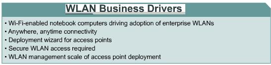
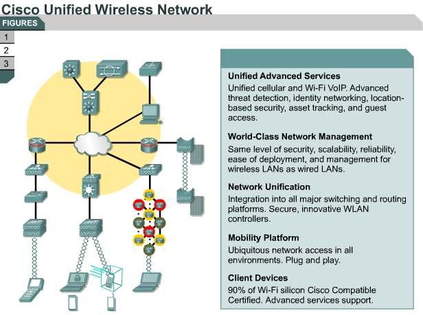
56 56

57 6.3.2Cisco WLAN Implementation and Components Cisco offers two WLAN implementations as shown in Figure : Autonomous WLAN: The autonomous WLAN solution uses autonomous access points. Lightweight WLAN: The lightweight WLAN solution uses lightweight access points and wireless LAN controllers. The available WLAN components are listed in Figure : Wireless clients connected to the network (for example, notebooks or IP phones). Access points build the WLAN infrastructure. o Autonomous access points are configured independently. o Lightweight access points are configured through LAN controllers. Radio monitoring and control is provided as follows: o Autonomous access points aggregate information through Wireless Domain Services (WDS) that in turn forward the information to a CiscoWorks Wireless LAN Solution Engine (WLSE). o Lightweight access points use LWAPP encapsulation to forward information independently to the access points respective WLAN controllers. WLAN management administers and monitors large deployments of WLANs as follows: o Autonomous access points use CiscoWorks WLSE management. o Lightweight access points use Cisco Wireless Control System (WCS) management. The network infrastructure includes switches and routers to connect access points, controllers, management, and servers. Network services such as DHCP, DNS, and AAA are required both for the wireless network and the user. 57
58 Cisco Aironet bridges operate at the MAC address layer (data link layer). Comparison of the WLAN Solutions Figure compares autonomous and lightweight WLAN solutions by characteristics and advantages: Autonomous access points: Autonomous access points are configured per access point. Their Cisco IOS software operates independently. CiscoWorks WLSE performs centralized configuration, monitoring, and management. WDS facilitates radio monitoring and management communication between the autonomous access points and CiscoWorks WLSE. WDS is a feature that is enabled in any access point that forwards aggregated RF information from a grouping of access points to CiscoWorks WLSE. Lightweight access points: You configure lightweight access points by using the Cisco Wireless LAN Controller. The access points usually depend on the controller for control and data transmission. Only in Remote-Edge Access Point (REAP) mode does a lightweight access point not depend on the Cisco Wireless LAN Controller for data transmission. The controller implements monitoring and security. Centralized configuration, monitoring, and management can be performed through Cisco WCS. Cisco Wireless LAN Controllers can be installed with redundancy within wireless LAN controller groups. 58
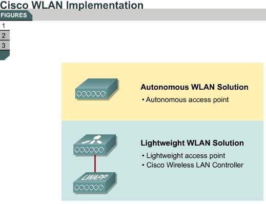
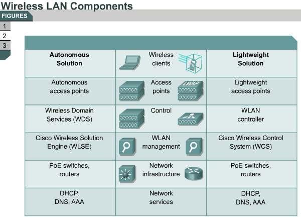
59 59

60 6.3.3CiscoWorks WLSE for the Autonomous WLAN Solution CiscoWorks WLSE is a systems-level solution for managing the entire Cisco Aironet WLAN infrastructure based on autonomous access points. The RF and device-management features of CiscoWorks WLSE simplify the everyday operation of WLANs, helping to ensure smooth deployment of security and network availability while reducing deployment and operating expense. CiscoWorks WLSE operates by gathering fault, performance, and configuration information about Cisco devices that CiscoWorks WLSE discovers in the network. You must configure the access points, WDS, switches, and routers with Cisco Discovery Protocol (CDP) and Simple Network Management Protocol (SNMP) to provide information to CiscoWorks WLSE for the access point discovery process. After WLSE discovers devices, you decide which devices to manage with CiscoWorks WLSE. CiscoWorks WLSE is a core component of the WLAN autonomous access-point solution. CiscoWorks WLSE has these major features, summarized in Figure : Configuration: Allows you to apply configuration changes to access points. Up to 2500 access points can be supported from a single CiscoWorks WLSE console. All Cisco Aironet access points are supported. Fault and policy monitoring: Monitors device fault and performance conditions, Lightweight Extensible Authentication Protocol (LEAP) server responses, and policy misconfigurations. Reporting: Allows you to track device, client, and security information. You can e- mail, print, and export reports. Firmware: Allows you to upgrade the firmware on access points and bridges. Radio management: Helps you manage your WLAN radio environment. CiscoWorks WLSE administration: Manages CiscoWorks WLSE software, including software upgrades, monitoring CiscoWorks WLSE, backing up data, and using two CiscoWorks WLSE devices as a redundant, highly available WLAN management solution. CiscoWorks WLSE supports warm-standby redundancy. A backup server can take over wireless management if there is a primary CiscoWorks WLSE failure. Deployment wizard: Configures and discovers access points that are used in a Cisco Unified Wireless Network. 60
61 CiscoWorks WLSE Key Benefits Using CiscoWorks WLSE to manage autonomous access points provides many benefits. CiscoWorks WLSE provides centralized management and RF visibility for Cisco Aironet autonomous access points and bridges. This solution gives users many benefits as listed in Figure : Improved WLAN security: Wireless IDS for rogue access points, ad hoc networks, excess management frames that signal denial-of-service (DoS) attacks and man-in-the-middle attacks Simplified access point deployment: Configuration policies that are created using Deployment Wizard are automatically applied to new access points RF visibility: RF coverage, received signal strength indicator (RSSI) displays, rogue access point location, and roaming boundaries Dynamic RF management: Self-healing, assisted site survey, automatic re-site survey, interference detection, and associated access point tracking for clients Simplified operations: Template-based configuration and image updates, reporting, and threshold-based monitoring The screen shot in Figure represents one of the many uses of CiscoWorks WSLE. This example illustrates scanning and monitoring capabilities showing the locations and coverage of Cisco Aironet access points on a building plan. CiscoWorks WLSE and WLSE Express CiscoWorks WLSE is used for centralized management of wireless networks that use autonomous access points. CiscoWorks WLSE supports the following WLAN devices: Cisco Aironet autonomous access points and bridges Access point- and Cisco Catalyst 6500 Series Wireless LAN Services Module (WLSM)-based WDS CiscoWorks WLSE supports Secure Shell (SSH), HTTP, CDP, and SNMP host resources MIB. CiscoWorks WLSE integrates with CiscoWorks wired management tools and third-party network management systems (NMSs): Simple Object Access Protocol (SOAP) Extensible Markup Language (XML) application programming interface (API) for data export SNMP trap and syslog forwarding for faults Figure illustrates the two available versions of CiscoWorks WLSE. Each version meets the needs of different network sizes and topologies: CiscoWorks WLSE: CiscoWorks WLSE supports medium to large enterprise and wireless verticals (up to 2500 WLAN devices). CiscoWorks WLSE Express: CiscoWorks WLSE Express provides a cost-effective solution with integrated WLAN management and security services to small to medium businesses (SMBs) (250 to 1500 employees) and commercial and branch offices (up to 100 WLAN devices). Enterprise branch office deployments usually want to localize WLAN security and management services to provide WLAN access survivability during WAN failures and not use their WAN bandwidth for WLAN and RF management traffic. Some service providers can use CiscoWorks WLSE Express because public WLAN (PWLAN) hot-spot management requires fewer WLAN devices. CiscoWorks WLSE requires an external AAA server, which is already included with CiscoWorks WLSE Express. CiscoWorks WLSE Express has integrated WLAN security and management services that support 802.1x LEAP, Protected Extensible 61
, Microsoft Active Directory, and a local user database.")
62 Authentication Protocol (PEAP), Extensible Authentication Protocol-Flexible Authentication via Secure Tunneling (EAP-FAST), and Extensible Authentication Protocol-Transport Layer Security (EAP-TLS). The user directory supports Lightweight Directory Access Protocol (LDAP), Microsoft Active Directory, and a local user database. CiscoWorks WLSE Express services support both wired and wireless user authentication and WLAN IDS features. 62


63 6.3.4Simplified CiscoWorks WLSE Express Setup You can use manual setup commands, but using CiscoWorks WLSE Express simplifies the setup, as described in Figure : 63
64 Automatic: After you have installed CiscoWorks WLSE Express, you can arrange for CiscoWorks WLSE to be autoconfigured. As each CiscoWorks WLSE is started for the first-time, a special configuration file is automatically downloaded, and CiscoWorks WLSE is ready for use. The configuration is downloaded from a DHCP server. The DHCP option is enabled by default. A TFTP IP address and filename are provided with options 66 and 67. CiscoWorks WLSE Express downloads a configuration, including host name, default gateway, and so on. Manual: By default, the CiscoWorks WLSE Express Ethernet interface is set to DHCP mode. When powered on, a CiscoWorks WLSE attempts to obtain the network configuration from a DHCP server. If you do not want to configure a DHCP server with this information, you can log in and configure the network parameters manually after CiscoWorks WLSE starts. You can manually configure CiscoWorks WLSE Express using the setup script and entering command-line interface (CLI) commands. Configuration Templates CiscoWorks WLSE has a web-based GUI with templates for configuration. Figure shows the interface template. Besides configuration and monitoring, CiscoWorks WLSE supports performance optimization and high availability. CiscoWorks WLSE supports centralized configuration and image management using several templates: Plug-and-play deployment Automatic configuration of access points added to CiscoWorks WLSE Automatic RF configuration of access points Calculation of optimal RF configurations by access points CiscoWorks WLSE includes WLAN intrusion detection with the following features: Detection of location and automatic shutdown of rogue access points via disabled switch ports Ad hoc network detection Man-in-middle detection by monitoring message integrity check (MIC) failures Access point configuration monitor to ensure that security policies are always enforced Sensor mode access points that can augment WLAN deployments for enhanced features CiscoWorks WLSE is designed for all day-to-day operations as well as for performance optimization and high availability using built-in Auto Re-Site Survey and Self Healing tools. Using Auto Re-Site Survey, CiscoWorks WLSE can provide optimal channel and power-level settings based on the access point air and RF monitoring phase of Assisted Site Survey only. Client walkabout is not needed, but performing client walkabouts during the Assisted Site Survey is recommended. Client walkabout increases the coverage for RF management and makes the survey more effective. CiscoWorks WLSE can detect that an access point has failed. CiscoWorks WLSE compensates for the loss by automatically increasing the power and cell coverage of nearby access points. The Self Healing feature minimizes the outage impact to wireless client devices and maximizes the availability of wireless applications. Self Healing also recalculates power coverage when the radio comes back up. 64


65 6.3.5CiscoWorks WLSE Benefits CiscoWorks WLSE reduces total cost of ownership, minimizes security vulnerabilities, and improves WLAN uptime. Figure summarizes the features and benefits of CiscoWorks WLSE: CiscoWorks WLSE supports centralized configuration, firmware, and radio management, which reduces WLAN total cost of ownership by saving the time and resources that you require to manage large numbers of access points. CiscoWorks WLSE aggregates all configurations, images, and management information in one place. Templates, one of the features of CiscoWorks WLSE, allow autoconfiguration of new access points for simplified large-scale deployment of access points. When a new access point is added to the system, you can use the template to configure the access point. Access points that you add to the system require correct configuration. CiscoWorks WLSE detects misconfiguration and follows with an alert. This process is also the process CiscoWorks WLSE uses to detect a rogue access point and to minimize security vulnerabilities. CiscoWorks WLSE is capable of monitoring access point use and client association. You can use a report that includes the number of access points and clients for capacity planning and troubleshooting. 65

66 The CiscoWorks WLSE configuration templates are not only used for new access points. The system allows proactive monitoring of access points, bridges, and 802.1x EAP servers. The system is able to push down configuration changes to access points, improving WLAN uptime Cisco WCS for the LWLAN Solution Cisco WCS is a Cisco WLAN solution network-management tool that adds to the capabilities of the web user interface and CLI, moving from individual controllers to a network of controllers. Cisco WCS includes the same configuration, performance monitoring, security, fault management, and accounting options that are used at the controller level and adds a graphical view of multiple controllers and managed access points. Figure is a representation of the complete functionality of Cisco WCS. Cisco WCS runs on Microsoft Windows and Linux platforms. Cisco WCS can run as a normal application or as a service, which runs continuously and resumes running after a reboot. The Cisco WCS user interface enables operators to control all permitted Cisco WLAN solution configuration, monitoring, and control functions through Microsoft Internet Explorer 6.0 or later. The administrator can define operator permissions using the Cisco WCS user interface Administration menu. This menu enables the administrator to manage user accounts and schedule periodic maintenance tasks. Cisco WCS simplifies controller configuration and monitoring while reducing data-entry errors with the Cisco Wireless LAN Controller autodiscovery algorithm. Cisco WCS uses SNMP to communicate with the controllers. Cisco WCS software is the industry-leading platform for WLAN planning, configuration, and management. The software provides a powerful foundation that IT managers can use to design, control, and monitor enterprise wireless networks from a centralized location, simplifying operations and reducing the total cost of ownership. Flexible and secure NMSs are made possible by an intuitive GUI with a browser that is accessible via HTTPS. Cisco WCS supports SNMP version 1 (SNMPv1), SNMPv2, and SNMPv3. Figure summarizes these points. Cisco provides a variety of options for efficiently tracking wireless devices, including Wi-Fienabled laptops, personal digital assistants (PDAs), voice handsets, and mobile assets that are equipped with transceivers. You can deploy Cisco WCS in any of the following three versions, illustrated in Figure : Cisco WCS Base: The base version of Cisco WCS can determine which access point a wireless device is associated with, giving IT managers a general approximation of 66
67 where wireless devices are situated. Cisco WCS Location: Environments that require more granular location services can implement an optional version of Cisco WCS, called Cisco WCS Location that uses Cisco's patent-pending RF fingerprinting technology. This technology compares realtime client RSSI information to known RF building characteristics, making Cisco the only WLAN infrastructure with the ability to locate a wireless device accurately to within a few meters. Cisco Wireless Location Appliance: In addition, Cisco WCS Location can be deployed in conjunction with Cisco Wireless Location Appliance to track thousands of wireless clients in real time, simultaneously. With these advanced location-tracking capabilities, the Cisco Unified Wireless Network is an ideal platform for helping to enable key business applications that take advantage of wireless mobility, such as asset tracking, inventory management, and enhanced 911 (e911) services for voice. By incorporating indoor location tracking into the wireless LAN infrastructure itself, Cisco reduces the complexities of wireless LAN deployment and minimizes total cost of ownership. 67
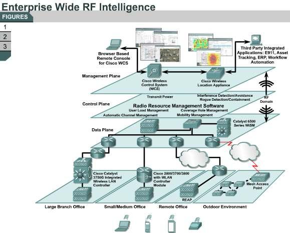
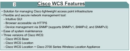
68 68

69 6.3.7Cisco WCS Software Features The Cisco WCS operating system manages all data client, communications, and system administration functions, performs radio resource management (RRM) functions, manages system-wide mobility policies using the operating system security solution, and coordinates all security functions using the operating system security framework. Cisco WCS Base Software Features Figure summarizes the features of Cisco WCS Base. Cisco WCS Base supports wireless client data access, rogue access point detection and containment functions (such as real-time location of rogue access points to the nearest Cisco access point and real-time and historical location of clients to the nearest Cisco access point), and Cisco WLAN solution monitoring and control. Cisco WCS software features include graphical views of the following: Autodiscovery of access points as the access points associate with controllers Autodiscovery and containment or notification of rogue access points Map-based organization of access point coverage areas, which is helpful when the enterprise spans more than one geographical area User-supplied campus, building, and floor plan graphics, which show this information: o Locations and status of managed access points o Locations of rogue access points based on the signal strength received by the nearest managed Cisco access points o Coverage hole alarm information for access points based on the received signal strength from clients appears in tabular rather than map format o RF coverage maps Cisco WCS Base also provides system-wide control of the following: Configuration using customer-defined templates for controllers and managed access points Status and alarm monitoring of network, controllers, and managed access points 69
70 Automated and manual data client monitoring and control functions Automated monitoring of rogue access points, coverage holes, security violations, controllers, and access points Full event logs for data clients, rogue access points, coverage holes, security violations, controllers, and access points Automatic channel and power level assignment by RRM User-defined automatic controller status audits, missed trap polling, configuration backups, and policy cleanups Cisco WCS Location Software Features Figure summarizes the features of Cisco WCS Location. Cisco WCS Location includes all the features of Cisco WCS Base as well as these enhancements: On-demand location of rogue access points to within 33 feet (10 meters) On-demand location of clients to within 33 feet The ability to use location appliances to collect and return historical location data that you can view in the Cisco WCS Location user interface The Cisco Wireless Location Appliance can be used to improve the functionality of Cisco WCS Location. The Cisco Wireless Location Appliance performs location computations based on the RSSI information that arrives from Cisco Wireless LAN Controllers. The Cisco Wireless LAN Controllers that gather the RSSI information must be associated with the Cisco Wireless Location Appliance. You can use the Cisco 2710 Series Location Appliance (explained later in this lesson) as a Cisco Wireless Location Appliance. Cisco WCS Deployment Figure represents a deployment of Cisco WCS. The Cisco WLAN solution consists of Cisco Wireless LAN Controllers and their associated lightweight access points controlled by the operating system, all concurrently managed by any or all of the operating system user interfaces. The following user interfaces exist: An HTTPS full-featured web user interface hosted by Cisco controllers can be used to configure and monitor individual controllers. A full-featured CLI can be used to configure and monitor individual controllers. Cisco WCS can be used to configure and monitor one or more controllers and associated access points. Cisco WCS has tools to facilitate large-system monitoring and control. An industry-standard SNMPv1, SNMPv2c, and SNMPv3 interface can be used with any SNMP-compliant third-party network management system. Minimum Client Server Requirements for Cisco WCS Cisco WCS is supported under Microsoft Windows 2000, Windows 2003, and Red Hat Enterprise Linux ES v.3 servers as either a normal application or a service. There are some minimum server requirements: Windows 2000 Service Pack (SP) 4 or greater, Windows 2003 SP1 or greater, or Red Hat Enterprise Linux ES v.3 Up to 500 access points: 2.4-GHz Pentium with 1-GB RAM More than 500 access points: dual processors (at least 2.4 GHz each) with minimum 2-GB RAM 20-GB hard drive The minimum client requirement is Internet Explorer 6.0 with SP1 or later. 70


71 6.3.8Cisco WCS User Interface The Cisco WCS user interface enables the network operator to create and configure Cisco WLAN solution coverage area layouts, configure system operating parameters, monitor realtime Cisco WLAN solution operation, and perform troubleshooting tasks using an HTTPS web 71
72 browser window. The Cisco WCS user interface also enables the WCS administrator to create, modify, and delete user accounts; change passwords; assign permissions; and schedule periodic maintenance tasks. The administrator creates new usernames and passwords and assigns them to predefined permissions groups. Note We recommend that you use Microsoft Internet Explorer 6.0 or later on a Windows workstation for full access to Cisco WCS functionality. Menu Bar There are four menus on each screen. When you move the mouse over any of the menu items, a drop-down menu appears: Monitor: The Monitor menu provides you with a top-level description of the devices on your network. Configure: The Configure menu allows you to configure templates, controllers, and access points on your network. Location: The Location menu allows you to configure Cisco Wireless Location Appliances. Administration: The Administration menu allows you to schedule tasks such as making a backup, checking device status, auditing your network, synchronizing the location server, and so on. Example: Cisco WCS Controller Network Summary Page As an example of the user interface, Figure shows the Cisco WCS Network Summary Page. This page provides a top-level description of your network and includes information about controllers, coverage areas, access points, clients, and so on. Note The Location menu is displayed only with Cisco WCS Location. Example: Cisco WCS Controller Summary Page Cisco WCS is designed to support 50 Cisco Wireless LAN Controllers and 1500 access points. The Controller Summary page provides access to the controller summary details. Use the selector area to access details for the respective controllers. Figure represents an example of the Controller Summary page. The data area of this screen contains a table with the following information: IP address: Local network IP address of the controller management interface. Select the title to toggle from ascending to descending order. Select an IP address in the list to display Controllers > <IP address> > Summary. Controller name: Select the title to toggle from ascending to descending order. Location: The geographical location (such as a campus or building). Select the title to toggle from ascending to descending order. Mobility group name: Name of the controller mobility or Microsoft Wireless Provisioning Services (WPS) group. Reachability status: Reachable or unreachable. Select the title to toggle from ascending to descending order. 72


73 6.3.9Cisco Wireless Location Appliance Cisco Wireless Location Appliance Overview The Cisco Wireless Location Appliance is an innovative, easy-to-deploy solution that uses 73
74 advanced RF fingerprinting technology to track thousands of wireless devices simultaneously from directly within a WLAN infrastructure, increasing asset visibility and control of the airspace. Figure shows a Cisco 2710 Series Wireless Location Appliances which are servers that enhance the high-accuracy built-in Cisco WCS location abilities by computing, collecting, and storing historical location data for up to 1500 laptop clients, palmtop clients, VoIP telephone clients, radio frequency identifier (RFID) asset tags, rogue access points, and rogue access point clients on a single chassis. Additionally, the appliance provides location-based alerts for business policy enforcement and records rich historical location information that can be used for location trending, rapid problem resolution, and RF capacity management. By design, the Cisco 2710 Series Wireless Location Appliance is integrated directly into the WLAN infrastructure to lower total cost of ownership and extend the value and security of the existing WLAN infrastructure by making the appliance location aware. As a component of the Cisco Unified Wireless Network, the Cisco Wireless Location Appliance uses Cisco Wireless LAN Controllers and Cisco Aironet lightweight access points to track the physical location of wireless devices to within a few meters. Moreover, the centralized WLAN management capabilities and intuitive GUI of Cisco WCS are extended for managing and configuring the Cisco Wireless Location Appliance, making setup fast and intuitive. Cisco Wireless Location Appliance Architecture Figure is a representative deployment of the Cisco Wireless Location appliance. A Cisco 2710 Series Wireless Location Appliance acts as a server to one or more Cisco WCS devices, collecting, storing, and passing on data from the appliance s associated Cisco Wireless LAN Controllers. The Cisco Wireless Location Appliance uses the same Cisco lightweight access points that deliver traffic as location readers for wireless clients and Wi-Fi tags. These access points collect RSSI information from all Wi-Fi devices, including Wi-Fi-enabled laptops, voice handsets, Wi-Fi tags, rogue devices and rogue access points. The collected RSSI information is then sent through Lightweight Access Point Protocol (LWAPP) to the Cisco Wireless LAN Controllers or certain wireless integrated switches or routers. Note Wi-Fi tags, which transmit wireless signals, are tags added to equipment to make tracking easier. Access points can collect RSSI information that you can use later for processing. The Cisco Wireless LAN Controllers then aggregate the RSSI information and send the information to the Cisco Wireless Location Appliance through SNMP. The Cisco Wireless Location Appliance performs location computations based on the RSSI information that arrives from the Cisco Wireless LAN Controllers. The Cisco Wireless LAN Controllers that gather the RSSI information must be associated with the Cisco Wireless Location Appliance. After network maps and access points are added to the appliance, RF predictions and heat maps can be generated to display the location of thousands of devices on the site floor plans graphically. Cisco WCS displays location information visually, providing an immediate location application for customers that want to enhance their RF capacity management, use locationbased security, and maintain asset visibility for WLAN devices. This location information is also available to third-party applications through a Simple Object Access Protocol (SOAP) XML API on the appliance, creating an extensible foundation for a host of rich location-based applications. SOAP is a protocol specification for invoking methods on servers, services, components, and objects. 74
75 Cisco WCS manages the Cisco Wireless Location Appliance through an intuitive and visually rich GUI providing centralized management and configuration. For greater scalability, Cisco WCS can manage one or more Cisco Wireless Location Appliances. The Cisco WCS view filters and flexible search criteria make targeted viewing of location data easy and adaptive to user needs. Cisco Wireless Location Appliance Applications After being configured, each location server communicates directly with the Cisco Wireless LAN Controllers that the server was assigned to in order to collect operator-defined location data. You can then use the associated Cisco WCS server to communicate with each location server to transfer and display selected data. You can configure appliances to collect data for Cisco WLAN solution clients, access points, mobile stations, and RFID asset Wi-Fi tags at intervals that you define. The collected information is used for tracking. Tracking of up to 1500 devices for a 30-day period is enabled. The Cisco Wireless Location Appliance can be deployed in a wide variety of environments and situations across multiple industries. Figure summarizes some of the primary use scenarios: Visibility and tracking of mobile devices by using Wi-Fi tags: Operating and capital expenses can be reduced by preventing loss or theft of valuable mobile assets such as wheelchairs and infusion pumps in a healthcare environment and overhead projectors, laptops, and voice handsets in an enterprise. Individuals and assets can be quickly located anywhere within a wireless environment. Work-flow automation and people tracking: Inventory use and electronic work-flow and dispatch processes are optimized. In a retail environment, store layout and queue management can be optimized based on tracking customer shopping patterns. In amusement parks, children can be tracked, allowing parents to know where the children are at all times, and security personnel can be tracked in any relevant facility. Telemetry: You can attach Wi-Fi tags with serial interfaces to a piece of equipment to relay important information about the device directly to business applications. For instance, car rental businesses often want telemetric information relating to mileage and fuel level of returned cars. WLAN security and network control: IT staff can rapidly locate security threats, such as rogue access points and rogue client devices. IT managers can also use the location appliance to establish a framework for location-based security, where the physical security in a building is used to control WLAN access, enhancing WLAN security. RF capacity management and visibility: Integrating location tracking into the WLAN allows IT staff to do more than just track users. With the Cisco Wireless Location Appliance, the staff can generate location-based trend reports and analyze the changes in traffic patterns, helping to enable better real-time RF capacity management. 75
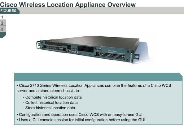
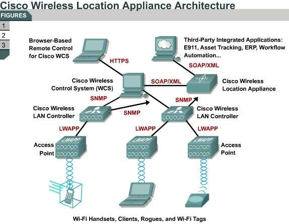
76 76

77 6.4.1Cisco WCS Configuration Example Cisco WCS Server Login Complete these steps to log in to the Cisco WCS server: Step 1 Launch Microsoft Internet Explorer version 6.0 or later. Note Some Cisco WCS features might not function properly if you use a web browser other than Internet Explorer 6.0 on a Windows workstation. Step 2 Step 3 In the browser address line, enter when the Cisco WCS user interface is on a Cisco WCS server. Enter when the Cisco WCS interface is on any other workstation. The Cisco WCS user interface displays the Cisco WCS Login page. On the login page, enter your username and password. The default username is root and the default password is public. Figure shows the screens and windows that appear. Cisco WCS Network Summary After successful login, Cisco WCS is ready to use. The Network Summary page is shown in Figure, from which the operator can start adding the devices and configuring the system using both horizontal and vertical main menus and submenus. The Cisco WCS user interface becomes active and available for use after login and displays the Network Summary (Network Dashboard) page. The Network Summary provides a summary of the Cisco WLAN solution, including reported coverage holes, access point operational data, the most recently detected rogue access points, and client distribution over 77
78 time. When Cisco WCS receives alarm messages from the controller, the Cisco WCS user interface displays an alarm in an indicator in the lower-left corner area known as the Alarm Monitor. Alarms indicate the current fault or state of an element that needs attention. One or more events will generate alarms. You can clear the alarms, but the event remains. Alarm color codes are given in the Alarm Color Code table. Alarm Color Codes Color Code Clear Red Orange Yellow Type of Alarm No alarm Critical alarm Major alarm Minor alarm 78


79 6.4.2Adding a Cisco Wireless LAN Controller to Cisco WCS Figure shows the page that you use to add and change Cisco Wireless LAN Controllers in the Cisco WCS database. When you know the IP address of a controller, follow these steps to add the controller to the Cisco WCS database: 79
80 Note We recommend that you manage controllers through the controller dedicated service port for improved security. However, when you manage controllers on which the service port is disabled or when you manage a controller that does not have a service port (such as a Cisco 2000 Series Wireless LAN Controller), you must use the controller management interface. Step 1 Step 2 Step 3 Step 4 Step 5 Log in to the Cisco WCS user interface. Choose Configure > Controllers. The All Controllers page appears. From the Select a command drop-down list, choose Add Controller, and then click Go. The Add Controller page appears. Enter the controller IP address, network mask, and required SNMP settings in the Add Controller fields. Click OK. Cisco WCS displays the Please Wait dialog box while contacting the controller. Cisco WCS adds the current controller configuration to the Cisco WCS database and then displays the Add Controller page again. If Cisco WCS does not find a controller at the IP address that you entered for the controller, the Discovery Status dialog displays this message, No response from device, check SNMP. Check these settings to correct the problem: The controller service port IP address might be set incorrectly. Check the service port setting on the controller. Cisco WCS might not have been able to contact the controller. Make sure that you can ping the controller from the Cisco WCS server. The SNMP settings on the controller might not match the SNMP settings that you entered in Cisco WCS. Make sure that the SNMP settings that are configured on the controller match the settings that you enter in Cisco WCS. Add additional controllers using the Add Controller page or choose the Configure tab to display the All Controllers page. 80


81 6.4.3Configuring a Cisco Access Point Access points that are associated to Cisco Wireless LAN Controllers are automatically added to Cisco WCS. To view all access points, choose Configure > Access Points as shown in Figure. 81

82 This page allows you to view a summary of all Cisco lightweight access points in the Cisco WCS database. The page also allows you to add third-party access points and remove selected Cisco lightweight access points. Note There is no need to add Cisco lightweight access points to the Cisco WCS database. The operating system software automatically adds Cisco lightweight access points when the access points associate with existing Cisco Wireless LAN Controllers in the Cisco WCS database. The following information appears: Access point name Ethernet MAC Radio type Map location Controller Operational status Alarm status 6.4.4Adding a Campus Map to the Cisco WCS Database When you add maps to Cisco WCS, you can view your managed system on realistic campus, building, and floor plan maps. Complete the steps shown in Figures and to add a single campus map to the Cisco WCS database: Step 1 Save the map in.png,.jpg,.jpeg, or.gif format. The map can be any size because Cisco WCS automatically resizes the map to fit the 82
83 working areas. Step 2 Step 3 Step 4 Step 5 Step 6 Step 7 Step 8 Step 9 Step 10 Browse to and import the map from anywhere in your file system. Choose the Monitor tab. Choose Maps to display the Maps page. From the Select a command drop-down list, choose New Campus, and then click OK to display the New Campus page. On the New Campus page, enter the campus name and campus contact information. Choose Browse to search for and select the campus graphic name. Check the Maintain Aspect Ratio check box to prevent length and width distortion when Cisco WCS resizes the map. Enter the horizontal span and the vertical span of the map in feet. The campus horizontal span and vertical span should be larger than any building or floor plan that may be added to the campus. Click OK to add the campus map to the Cisco WCS database. Cisco WCS displays the Maps page, which lists maps in the database, map types, and campus status. 83


84 6.4.5Adding New Building to the Cisco WCS Database You can add buildings to the Cisco WCS database whether or not you have added maps or campuses to the database. Follow these steps to add a building to a campus in the Cisco WCS database as shown in Figure : 84
85 Step 1 Step 2 Step 3 Step 4 Step 5 Choose the Monitor tab. Choose Maps to display the Maps page. Choose the desired campus. Cisco WCS displays the Campus page. From the Select a command drop-down list, choose New Building, and then click Go to display the New Building page. On the New Building page, follow these steps to create a virtual building to organize related floor plan maps: 1. Enter the building name. 2. Enter the building contact name. 3. Enter the number of floors and basements. 4. Enter an approximate building horizontal span and vertical span (width and depth on the map) in feet. These numbers should be as large as or larger than any floors that you might add later. Tip You can also press Ctrl-Left-Select to resize the bounding area in the upper-left corner of the campus map. As you change the size of the bounding area, the Building Horizontal Span and Vertical Span parameters vary to match your changes. Step 6 Step 7 Step 8 Choose Place to put the building on the campus map. Cisco WCS creates a building rectangle scaled to the size of the campus map. Select the building rectangle and drag the rectangle to the desired position on the campus map. Choose Save to save the building definition and campus location in the database. Cisco WCS saves the building name in the building rectangle on the campus map. Note that there will be a hyperlink associated with the building that takes you to the corresponding Maps page. 85

86 6.4.6Rogue Access Point Detection When the lightweight access points on your WLAN are powered up and associated with controllers, Cisco WCS immediately starts listening for rogue access points. When the Cisco Wireless LAN Controller detects a rogue access point, the controller immediately notifies Cisco WCS, which creates a rogue access point alarm. Figure shows that WCS located 93 rogue access points. When Cisco WCS receives a rogue access point message from a Cisco Wireless LAN Controller, an alarm indicator appears in the lower-left corner of all Cisco WCS user interface pages. Select the indicator to display the Rogue AP Alarms page. Figure shows a representative Rogue AP Alarms page that lists the severity of the alarms, the rogue access point MAC addresses, the rogue access point types, the owners (Cisco WCS operators), the date and time when the rogue access points were first detected, the channel numbers the access points are broadcasting on, and the access point service set identifiers (SSIDs). The four boxes at the bottom of the page represent the drop-down menus you can access from the Alarm panel on the left. They represent the Severity, Alarm Category, Rogue AP State, and Search all APs by menus. On this page, you can highlight one or more entries by checking the desired check boxes and choosing one of the following commands from the Select a command drop-down list to apply to all selected rogue access point alarms: Assign to Me, Unassign, Delete, Clear, or Notification. To see more rogue access point information, click any link in the Rogue MAC Address column to display the associated Alarms > Rogue AP MAC Address page. 86


87 6.4.7Rogue Access Point Location On the Rogue AP MAC Address page, choose Map to display the currently calculated rogue access point location on the Maps > Building Name > Floor Name page. If you are using Cisco WCS Location, Cisco WCS compares the RSSI signal strength from two or more access points to find the most probable location of the rogue access point and places a small skull- 87
 relies on RSSI signal strength from the rogue access point and places a small skulland-crossbones indicator next to the access point receiving the")
88 and-crossbones indicator at the most likely location. Cisco WCS Base (without the Location option) relies on RSSI signal strength from the rogue access point and places a small skulland-crossbones indicator next to the access point receiving the strongest RSSI signal from the rogue unit. Figure shows the floor plan that Cisco WCS displays. To acknowledge known rogue access points, navigate to the Rogue AP Alarms page. Rightclick the rogue access point (red, unknown) that you want to acknowledge and choose Set State to Known Internal or Set State to Known External. In either case, Cisco WCS removes the red rogue access point entry from the Alarms page Configuring Open Authentication This lesson uses the Cisco Wireless LAN Controller GUI to configure encryption and authentication. This first topic configures open authentication. Open authentication is used when no authentication or encryption is desired. This is normal for a guest implementation for visitors or hot-spot applications. For existing wireless LANs (WLANs), choose WLANs, and then Edit, to navigate to this page. For new WLANs, create a new WLAN by choosing WLANs > New, and then click Apply to navigate to this page. This page allows you to edit the configurable parameters for a WLAN. The default authentication method for a new WLAN is 802.1x, which will be displayed. The reason for setting this parameter as the default is to protect against accidental open authentication. The next step is to change the value in the Layer 2 Security drop-down list under the Security Policies heading from 802.1x to None. Ensure that both the Layer 2 and Layer 3 Security fields are set to None. Note Depending on the security policy options selected, the bottom of the page will change to reflect the appropriate security parameters. 88

89 6.5.2Configuring Static WEP Key Authentication For existing WLANs, choose WLANs, and then Edit, to navigate to this page. For new WLANs, create a new WLAN by choosing WLANs > New, and then click Apply to navigate to this page. This page allows you to edit the configurable parameters for a WLAN. Choose Static WEP from the Layer 2 Security drop-down list under the Security Policies heading. The bottom of the screen will update to show the static Wired Equivalent Privacy (WEP) options with the appropriate parameters listed. The static WEP encryption parameters are as follows: Key sizes are 40/64, 104/128, and 128/152 bits. Key index is from 1 to 4. Enter the encryption key. Choose ASCII or HEX as the encryption key format. Note One unique WEP key index can be applied to each WLAN. Because there are only four WEP key indexes, only four WLANs can be configured for static WEP Layer 2 encryption. 89

90 6.5.3Configuring WPA Preshared Key For existing WLANs, choose WLANs, and then Edit, to navigate to this page. For new WLANs, create a new WLAN by choosing WLANs > New, and then click Apply to navigate to this page. This page allows you to edit the configurable parameters for a WLAN as shown in Figure : Choose WPA from the Layer 2 Security drop-down list under the Security Policies heading. The bottom of the page will change to reflect appropriate parameters for Wi- Fi Protected Access (WPA). Check the Enabled check box at the bottom of page for a preshared key. The bottom of the page will again change to reflect this option, and the Set Passphrase field will appear. Enter the WPA preshared key passphrase in the field. 90

91 6.5.4Configuring Web Authentication Web authentication allows users to authenticate through a web browser interface. Clients who attempt to access the WLAN using HTTP are automatically redirected to a login page. The login page is customizable for both logos and text. The maximum simultaneous authentication requests using web authentication is 21. The maximum number of local web authentication users is Web authentication is generally used for guest access, and you should bear in mind that client data is not secured between the client and the access point. Because there is no encryption, per-packet authentication, or message integrity check (MIC), users should use some other security mechanism after authentication. This authentication method does not protect against interception, hijacking, or packet modification. Note Web authentication is a feature of Cisco 4400 Series Wireless LAN Controllers and Cisco Catalyst 6500 Series Wireless Services Module (WiSM). It is not a feature of Cisco 2000 Series Wireless LAN Controllers or Cisco Integrated Services Routers Wireless LAN Controller Modules. Figure summarizes these points. Configure web authentication as follows: For existing WLANs, choose WLANs, and then choose Edit, to navigate to this page. For new WLANs, create a new WLAN by choosing WLANs > New, and then click Apply to navigate to this page. This page allows you to edit the configurable parameters for a WLAN. In the Layer 3 Security area shown in Figure, check the Web Policy check box to enable the 91


92 web policy. The bottom of the page will change to reflect this choice and offer the following parameters for web authentication: Authentication: If you choose this option, you will be prompted for username and password while the client is connecting to the wireless network. The authentication credentials will be verified against the controller internal user database. If no username is matched, then an external RADIUS server will be used if it is configured. Passthrough: If you choose this option, you can access the network directly without entering a username and password. This option might be used to simply present a legal notice before allowing access. o Input: This option is available for the Passthrough option only. If you choose this option, you will be prompted for an address when connecting to the network. Preauthentication ACL: Choose the access control list (ACL) to be used for traffic between the client and the controller. Note The controller will have to reboot to load and enable the web authentication feature Customizing the Web Login Page 92

93 Figure shows how to customize the web login page. Choose Management > Web Login Page to navigate to this page. You can customize the content and appearance of the web login page that appears the first time a user accesses the client. The Web Login page parameters are as follows: Use External Web Authentication: Enable this option and enter the URL if you want to use a customized login page configured on your web server for web authentication instead of the default web authentication page provided by the Cisco 4000 Series Wireless LAN Controllers. The maximum length is 254 characters. Note The following parameters will be displayed only if the Use External Web Authentication option is disabled. Redirect URL after Login: Enter the URL to which you want the user to be redirected after login. For example, you may enter your company URL here, and users will be directed to that URL after login. The maximum length is 254 characters. By default, the user is redirected to the URL that was entered in the user s browser before the login page appeared. Headline: Specify the login page headline; for example, Welcome to the Cisco Wireless Network. The maximum length is 127 characters. Message: Specify the login page message; for example, Please enter your username and password. or This page will not be available from 1:00 to 2:00 p.m. today because of maintenance. The maximum length is 2047 characters Configuring 802.1x Authentication Figure shows how to configure 802.1x authentication as follows: 93

94 For existing WLANs, choose WLANs, and then Edit, to navigate to this page. For new WLANs, create a new WLAN by choosing WLANs > New, and then click Apply to navigate to this page. This page allows you to edit the configurable parameters for a WLAN. Choose 802.1x from the Layer 2 Security drop-down list under the Security Policies heading. If this is a new WLAN ID, 802.1x will be the default authentication policy. The bottom of the screen will update to show the 802.1x options with the appropriate parameters x uses dynamic WEP keys. The options are these: 40/64 bits 104/128 bits 128/152 bits Note standards support 40/64- and 104/128-bit keys. 128/152-bit keys are supported by i, WPA, and WPA Configuring WPA with 802.1x Figure shows how to configure WPA with 802.1x as follows: For existing WLANs, choose WLANs, and then Edit, to navigate to this page. For new WLANs, create a new WLAN by choosing WLANs > New, and then click Apply to navigate to this page. This page allows you to edit the configurable parameters for a WLAN. Choose WPA from the Layer 2 Security drop-down list under the Security Policies heading. 94

95 Leave the Pre-Shared Key Enabled check box unchecked for WPA with dynamic keys. The authentication process will use dynamic Extensible Authentication Protocol (EAP) 802.1x authentication to a RADIUS server WPA2 Figure shows how to configure WPA2 as follows: For existing WLANs, choose WLANs, and then Edit, to navigate to this page. For new WLANs, create a new WLAN by choosing WLANs > New, and then click Apply to navigate to this page. This page allows you to edit the configurable parameters for a WLAN. Choose WPA-2 from the Layer 2 Security drop-down list under the Security Policies heading. The security policy options and parameters at the bottom of the page are as follows: WPA Compatibility Mode: This option allows support for both WPA and WPA2 clients on the same service set identifier (SSID) to support legacy systems during migration to WPA. Allow WPA-2 TKIP Clients: This option allows support of legacy hardware that cannot run Advanced Encryption Standard-Cipher Block Chaining Message Authentication Code Protocol (AES-CCMP) but can run WPA2. Pre-Shared Key: When this option is checked, you can choose to enable a preshared key with or without an 8- to 63-character Record Sequence Number (RSN) passphrase. 95

96 6.6.1Lab 6.1 Configuring a WLAN Controller Lab Activity Lab Exercise: Lab 6.1a Configuring a WLAN Controller In the next two labs, you will configure a wireless solution involving a WLAN controller, two lightweight wireless access points, and a switched wired network. You will configure a WLAN controller to broadcast SSIDs from the lightweight wireless access points. If you have a wireless client nearby, connect to the WLANs and access devices from the inside of your pod to verify your configuration of the controller and access points. Note It is required that you upgrade the WLC firmware image to or higher in order to accomplish this lab. 96
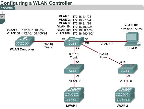
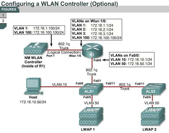
97 97
98 6.6.2Lab 6.2a Configuring a WLAN Controller via the Web Interface Lab Activity Lab Exercise: Lab 6.2a Configuring a WLAN Controller via the Web Interface Continuing from the previous lab, you will now set up the WLAN controller through its web interface. Previously you configured it through the CLI. Note It is required that you upgrade the WLC firmware image to or higher in order to accomplish this lab. Lab Activity Lab Exercise: Lab 6.2b Configuring a WLAN Controller via the Web Interface (Optional) This lab leverages an internal WLAN controller in the topology Lab 6.3 Configuring a Wireless Client Lab Activity Lab Exercise: Lab 6.3 Configuring a Wireless Client In this lab, you will install a Cisco Aironet wireless PC card on a laptop. Then you will also configure the Cisco Aironet Desktop Utility (ADU) to connect to an access point Lab 6.4 Configuring WPA Security with Preshared Keys Lab Activity Lab Exercise: Lab 6.4 Configuring WPA Security with Preshared Keys IIn this lab, you will configure and verify Wi-Fi Protected Access ( WPA) security in a wireless environment using preshared keys. This lab requires two separate PCs, Host A and Host B. Host A will act on VLAN 10 as the Cisco access control server (ACS) server and will also be used to configure the wireless LAN (WLAN) controller as a PC has been used to do in previous labs. Host B requires a Cisco wireless network card with the Aironet Desktop Utility installed. Host B will function as a wireless client on WLAN 1 which corresponds to VLAN 2. You may complete this scenario using either the external WLAN controller (WLC) or the network module that resides in a router. However, you must load the final configurations from the end of Lab 6.1: Configuring a WLAN Controller. We highly recommended that you complete Labs 6.1, 6.2, and 6.3 before attempting this lab. 98
99 Note This lab will only go into the details of configuring WLAN security using WPA-PSK. For more information on using the web interface of the WLC, consult Lab 6.2: Configuring a WLAN Controller via the Web Interface Lab 6.5 Configuring LEAP Lab Activity Lab Exercise: Lab 6.5 Configuring LEAP In this lab, you will configure and verify 802.1X security in a wireless environment. The 802.1X authentication protocol is built on the Extensible Authentication Protocol (EAP) and the RADIUS authentication protocol and provides per-client authentication and network admission. This lab requires two separate PCs, Host A and Host B. Host A will act on VLAN 10 as the Cisco access control server (ACS) and will also be used to configure the wireless LAN (WLAN) controller the way a PC has been used to do in previous labs. Host B requires a Cisco wireless network card with the Aironet Desktop Utility installed. Host B will function as a wireless client on WLAN 1 which corresponds to VLAN 2. You may complete this scenario using either the external wireless LAN controller (WLC) or the network module that resides in a router. However, you must load the final configurations from the end of Lab 6.1: Configuring a WLAN Controller. We highly recommend that you complete Labs 6.1, 6.2, and 6.3 before attempting this lab. Note This lab will only go into the details of configuring the 802.1X security protocol. For more information on using the web interface of the WLC, consult Lab 6.2: Configuring a WLAN Controller via the Web Interface.. Summary Video and voice applications are used with wireless clients as well as wired clients and QoS is required for both types of clients. To support QoS, WLANs use e or WMM scheduling and queuing. These QoS features are implemented on access points. Authentication and encryption are the two primary facilities for securing the WLAN. While encryption using static WEP keys is very vulnerable, WLANs can now be configured to support EAP and the 802.1x standards including LEAP, EAP-FAST, EAP-TLS, PEAP, WPA, and WPA2. Cisco offers two WLAN implementations: an autonomous and a lightweight WLAN solution. Autonomous access points are configured per access point, while lightweight access points are configured via the WLAN controller. CiscoWorks WLSE is a server that supports centralized configuration, firmware, and radio management. Cisco WCS is a Cisco WLAN solution network management tool used for WLAN planning, configuration, and management. Three Cisco WCS tracking options are available: WCS Base, WCS Location, and WCS Location and Cisco 2700 Series Wireless Location Appliance. The Cisco 2700 Series Wireless Location Appliance system is used for tracking of thousands of wireless devices. The user must supply the Cisco WCS software with campus, building, and floor plan graphics. 99
100 100
FAQ on Cisco Aironet Wireless Security
 FAQ on Cisco Aironet Wireless Security Document ID: 68583 Contents Introduction General FAQ Troubleshooting and Design FAQ Related Information Introduction This document provides information on the most
Wireless technology Principles of Security
 Wireless technology Principles of Security 1 Wireless technologies 2 Overview This module provides an introduction to the rapidly evolving technology of wireless LANs (WLANs). WLANs redefine the way the
D. The bank s web server is using an X.509 certificate that is not signed by a root CA, causing the user ID and password to be sent unencrypted.
 Volume: 119 Questions Question No: 1 John Smith uses a coffee shop's Internet hot-spot (no authentication or encryption) to transfer funds between his checking and savings accounts at his bank's website.
Wireless LAN Security. Gabriel Clothier
 Wireless LAN Security Gabriel Clothier Timeline 1997: 802.11 standard released 1999: 802.11b released, WEP proposed [1] 2003: WiFi alliance certifies for WPA 2004: 802.11i released 2005: 802.11w task group
Appendix E Wireless Networking Basics
 Appendix E Wireless Networking Basics This chapter provides an overview of Wireless networking. Wireless Networking Overview The FWG114P v2 Wireless Firewall/Print Server conforms to the Institute of Electrical
Network Access Flows APPENDIXB
 APPENDIXB This appendix describes the authentication flows in Cisco Identity Services Engine (ISE) by using RADIUS-based Extensible Authentication Protocol (EAP) and non-eap protocols. Authentication verifies
Outline : Wireless Networks Lecture 10: Management. Management and Control Services : Infrastructure Reminder.
 Outline 18-759: Wireless Networks Lecture 10: 802.11 Management Peter Steenkiste Departments of Computer Science and Electrical and Computer Engineering Spring Semester 2016 http://www.cs.cmu.edu/~prs/wirelesss16/
CYBER ATTACKS EXPLAINED: WIRELESS ATTACKS
 CYBER ATTACKS EXPLAINED: WIRELESS ATTACKS Wireless networks are everywhere, from the home to corporate data centres. They make our lives easier by avoiding bulky cables and related problems. But with these
CS-435 spring semester Network Technology & Programming Laboratory. Stefanos Papadakis & Manolis Spanakis
 CS-435 spring semester 2016 Network Technology & Programming Laboratory University of Crete Computer Science Department Stefanos Papadakis & Manolis Spanakis CS-435 Lecture preview 802.11 Security IEEE
Wireless Attacks and Countermeasures
 Wireless Attacks and Countermeasures Wireless Network Technology Wireless network refers to any type of computer network which is wireless, and is commonly associated with a network whose interconnections
Internetwork Expert s CCNP Bootcamp. Wireless LANs. WLANs replace Physical (layer 1) and Data Link (layer 2) transports with wireless
 and Data Link (layer 2) transports with wireless") Internetwork Expert s CCNP Bootcamp Wireless LANs http:// WLANs Overview WLANs replace Physical (layer 1) and Data Link (layer 2) transports with wireless Upper layer protocols like IP/TCP/UDP/etc. are
Internetwork Expert s CCNP Bootcamp Wireless LANs http:// WLANs Overview WLANs replace Physical (layer 1) and Data Link (layer 2) transports with wireless Upper layer protocols like IP/TCP/UDP/etc. are
What is Eavedropping?
 WLAN Security What is Eavedropping? War Driving War Driving refers to someone driving around with a laptop and an 802.11 client card looking for an 802.11 system to exploit. War Walking Someone walks
Managing and Securing Computer Networks. Guy Leduc. Chapter 7: Securing LANs. Chapter goals: security in practice: Security in the data link layer
 Managing and Securing Computer Networks Guy Leduc Chapter 7: Securing LANs Computer Networking: A Top Down Approach, 7 th edition. Jim Kurose, Keith Ross Addison-Wesley, April 2016. (section 8.8) Also
Summary. Deployment Guide: Configuring the Cisco Wireless Security Suite 1 OL
 Summary Numerous papers have been written on the topic of IEEE 802.11 security for wireless LANs (WLANs). The major vulnerabilities of 802.11 security can be summarized as follows: Weak device-only authentication:
Lab Configure Enterprise Security on AP
 Lab 8.5.4.1 Configure Enterprise Security on AP Estimated Time: 30 minutes Number of Team Members: Students will work in teams of two. Objective In this lab, students will demonstrate an understanding
PROTECTED EXTENSIBLE AUTHENTICATION PROTOCOL
 Q&A PROTECTED EXTENSIBLE AUTHENTICATION PROTOCOL This document answers questions about Protected Extensible Authentication Protocol. OVERVIEW Q. What is Protected Extensible Authentication Protocol? A.
Wireless LAN Security (RM12/2002)
") Information Technology in Education Project Reference Materials Wireless LAN Security (RM12/2002) Infrastructure Division Education Department The Government of HKSAR www.ited.ed.gov.hk December 2002 For
Information Technology in Education Project Reference Materials Wireless LAN Security (RM12/2002) Infrastructure Division Education Department The Government of HKSAR www.ited.ed.gov.hk December 2002 For
Security Setup CHAPTER
 CHAPTER 8 This chapter describes how to set up your bridge s security features. This chapter contains the following sections: Security Overview, page 8-2 Setting Up WEP, page 8-7 Enabling Additional WEP
IP network that supports DHCP or manual assignment of IP address, gateway, and subnet mask
 Network Requirements, page 1 Wireless LAN, page 2 Wi-Fi Network Components, page 3 802.11 Standards for WLAN Communications, page 6 Security for Communications in WLANs, page 9 WLANs and Roaming, page
Wireless# Guide to Wireless Communications. Objectives
 Wireless# Guide to Wireless Communications Chapter 8 High-Speed WLANs and WLAN Security Objectives Describe how IEEE 802.11a networks function and how they differ from 802.11 networks Outline how 802.11g
Configuring Authentication Types
 CHAPTER 11 This chapter describes how to configure authentication types on the access point. This chapter contains these sections: Understanding Authentication Types, page 11-2, page 11-10 Matching Access
TestsDumps. Latest Test Dumps for IT Exam Certification
 TestsDumps http://www.testsdumps.com Latest Test Dumps for IT Exam Certification Exam : PW0-200 Title : Certified wireless security professional(cwsp) Vendors : CWNP Version : DEMO Get Latest & Valid PW0-200
Configuring Cipher Suites and WEP
 10 CHAPTER This chapter describes how to configure the cipher suites required to use WPA authenticated key management, Wired Equivalent Privacy (WEP), Temporal Key Integrity Protocol (TKIP), and broadcast
Securing a Wireless LAN
 Securing a Wireless LAN This module describes how to apply strong wireless security mechanisms on a Cisco 800, 1800, 2800, or 3800 series integrated services router, hereafter referred to as an access
Standard For IIUM Wireless Networking
 INTERNATIONAL ISLAMIC UNIVERSITY MALAYSIA (IIUM) Document No : IIUM/ITD/ICTPOL/4.3 Effective Date : 13/11/2008 1.0 OBJECTIVE Standard For IIUM Wireless Networking Chapter : Network Status : APPROVED Version
Security in IEEE Networks
 Security in IEEE 802.11 Networks Mário Nunes, Rui Silva, António Grilo March 2013 Sumário 1 Introduction to the Security Services 2 Basic security mechanisms in IEEE 802.11 2.1 Hidden SSID (Service Set
Configuring a VAP on the WAP351, WAP131, and WAP371
 Article ID: 5072 Configuring a VAP on the WAP351, WAP131, and WAP371 Objective Virtual Access Points (VAPs) segment the wireless LAN into multiple broadcast domains that are the wireless equivalent of
CWNA Exam PW0-100 certified wireless network administrator(cwna) Version: 5.0 [ Total Questions: 120 ]
![CWNA Exam PW0-100 certified wireless network administrator(cwna) Version: 5.0 [ Total Questions: 120 ]](/thumbs/96/127708682.jpg "CWNA Exam PW0-100 certified wireless network administrator(cwna) Version: 5.0 [ Total Questions: 120 ]") s@lm@n CWNA Exam PW0-100 certified wireless network administrator(cwna) Version: 5.0 [ Total Questions: 120 ] Topic 1, A A Question No : 1 - (Topic 1) What criteria can an 802.11 wireless client use to
s@lm@n CWNA Exam PW0-100 certified wireless network administrator(cwna) Version: 5.0 [ Total Questions: 120 ] Topic 1, A A Question No : 1 - (Topic 1) What criteria can an 802.11 wireless client use to
The 8 th International Scientific Conference DEFENSE RESOURCES MANAGEMENT IN THE 21st CENTURY Braşov, November 14 th 2013
 The 8 th International Scientific Conference DEFENSE RESOURCES MANAGEMENT IN THE 21st CENTURY Braşov, November 14 th 2013 Florin OGÎGĂU-NEAMŢIU National Defense University of Romania "Carol I"/ The Regional
Chapter 24 Wireless Network Security
 Chapter 24 Wireless Network Security Wireless Security Key factors contributing to higher security risk of wireless networks compared to wired networks include: o Channel Wireless networking typically
Multi-Layered Security Framework for Metro-Scale Wi-Fi Networks
 Multi-Layered Security Framework for Metro-Scale Wi-Fi Networks A Security Whitepaper January, 2004 Photo courtesy of NASA Image exchange. Image use in no way implies endorsement by NASA of any of the
Numerics INDEX. 2.4-GHz WMIC, contrasted with 4.9-GHz WMIC g 3-6, x authentication 4-13
 INDEX Numerics 2.4-GHz WMIC, contrasted with 4.9-GHz WMIC 1-8 802.11g 3-6, 3-9 802.1x authentication 4-13 A AAA server group 4-25 aaa authentication login command 4-24 aaa authorization command 4-27 aaa
Csci388. Wireless and Mobile Security Access Control: 802.1X, EAP, and RADIUS. Importance of Access Control. WEP Weakness. Wi-Fi and IEEE 802.
 WEP Weakness Csci388 Wireless and Mobile Security Access Control:, EAP, and Xiuzhen Cheng cheng@gwu.edu 1. IV is too short and not protected from reuse 2. The per packet key is constructed from the IV,
Exam : PW Title : Certified wireless security professional(cwsp) Version : DEMO
 Version : DEMO") Exam : PW0-200 Title : Certified wireless security professional(cwsp) Version : DEMO 1. Given: John Smith often telecommutes from a coffee shop near his home. The coffee shop has an 802.11g access point
Exam : PW0-200 Title : Certified wireless security professional(cwsp) Version : DEMO 1. Given: John Smith often telecommutes from a coffee shop near his home. The coffee shop has an 802.11g access point
Wireless Network Security
 Wireless Network Security Why wireless? Wifi, which is short for wireless fi something, allows your computer to connect to the Internet using magic. -Motel 6 commercial 2 but it comes at a price Wireless
Configuring the Client Adapter
 CHAPTER 5 This chapter explains how to configure profile parameters. The following topics are covered in this chapter: Overview, page 5-2 Setting General Parameters, page 5-3 Setting Advanced Parameters,
Securing Your Wireless LAN
 Securing Your Wireless LAN Pejman Roshan Product Manager Cisco Aironet Wireless Networking Session Number 1 Agenda Requirements for secure wireless LANs Overview of 802.1X and TKIP Determining which EAP
Securing Wireless Networks by By Joe Klemencic Mon. Apr
 http://www.cymru.com/ Securing Wireless Networks by By Joe Klemencic (faz@home.com) Mon. Apr 30 2001 Many companies make attempts to embrace new technologies, but unfortunately, many of these new technologies
Wireless Network Security Fundamentals and Technologies
 Wireless Network Security Fundamentals and Technologies Rakesh V S 1, Ganesh D R 2, Rajesh Kumar S 3, Puspanathan G 4 1,2,3,4 Department of Computer Science and Engineering, Cambridge Institute of Technology
C I S C O C O M P A T I B L E E X T E N S I O N S : C L I E N T B E N E F I T S O N A C I S C O W L A N
 White Paper C I S C O C O M P A T I B L E E X T E N S I O N S : C L I E N T B E N E F I T S O N A C I S C O W L A N Overview Some of the most compelling benefits to working under a unified network architecture
Network Security and Cryptography. 2 September Marking Scheme
 Network Security and Cryptography 2 September 2015 Marking Scheme This marking scheme has been prepared as a guide only to markers. This is not a set of model answers, or the exclusive answers to the questions,
Configuring Layer2 Security
 Prerequisites for Layer 2 Security, page 1 Configuring Static WEP Keys (CLI), page 2 Configuring Dynamic 802.1X Keys and Authorization (CLI), page 2 Configuring 802.11r BSS Fast Transition, page 3 Configuring
Wireless Domain Services FAQ
 Wireless Domain Services FAQ Document ID: 65346 Contents Introduction What is WDS? How do I configure my AP as a WDS? On what platforms does Cisco Structured Wireless Aware Network (SWAN) WDS run? How
The following chart provides the breakdown of exam as to the weight of each section of the exam.
 Introduction The CWSP-205 exam, covering the 2015 objectives, will certify that the successful candidate understands the security weaknesses inherent in WLANs, the solutions available to address those
Advanced Security and Mobile Networks
 Advanced Security and Mobile Networks W.Buchanan (1) 9. GSM/3G Unit 7: Mobile Networks. Wireless. Security. Mobile IP. Mobile Agents. Spread spectrum. Military/Emergency Networks 8. Ad-hoc 7. Mobile Networks
Securing Wireless LANs with Certificate Services
 1 Securing Wireless LANs with Certificate Services PHILIP HUYNH University of Colorado at Colorado Springs Abstract Wireless Local Access Network (WLAN) is used popularly in almost everywhere from the
Wireless Security Protocol Analysis and Design. Artoré & Bizollon : Wireless Security Protocol Analysis and Design
 Protocol Analysis and Design 1 Networks 1. WIRELESS NETWORKS 2 Networks 1. WIRELESS NETWORKS 1.1 WiFi 802.11 3 Networks OSI Structure 4 Networks Infrastructure Networks BSS : Basic Set Service ESS : Extended
05 - WLAN Encryption and Data Integrity Protocols
 05 - WLAN Encryption and Data Integrity Protocols Introduction 802.11i adds new encryption and data integrity methods. includes encryption algorithms to protect the data, cryptographic integrity checks
WLAN Security Overview
 WLAN Security Overview This Chapter Explore the basic terminology of WLAN security. Discuss the organizations that create the standards, certifications, and recommendations that help guide and direct wireless
Viewing Status and Statistics
 CHAPTER 7 This chapter explains how to use ADU to view the client adapter s status and its transmit and receive statistics. The following topics are covered in this chapter: Overview of ADU and Statistics
WPA SECURITY (Wi-Fi Protected Access) Presentation. Douglas Cheathem (csc Spring 2007)
 Presentation. Douglas Cheathem (csc Spring 2007)") WPA SECURITY (Wi-Fi Protected Access) Presentation By Douglas Cheathem (csc 650.01 Spring 2007) OUTLINE Introduction Security Risk Vulnerabilities Prevention Conclusion Live Demo Q & A INTRODUCTION! WPA
WPA SECURITY (Wi-Fi Protected Access) Presentation By Douglas Cheathem (csc 650.01 Spring 2007) OUTLINE Introduction Security Risk Vulnerabilities Prevention Conclusion Live Demo Q & A INTRODUCTION! WPA
Configuring WEP and WEP Features
 CHAPTER 9 This chapter describes how to configure Wired Equivalent Privacy (WEP), Message Integrity Check (MIC), and Temporal Key Integrity Protocol (TKIP). This chapter contains these sections: Understanding
Wi-Fi Scanner. Glossary. LizardSystems
 Wi-Fi Scanner Glossary LizardSystems 2 Table of Contents 802 6 802.11 6 802.11a 6 802.11b 6 802.11d 6 802.11e 6 802.11g 6 802.11h 6 802.11i 6 802.11j 6 802.11n 7 802.1X 7 802.3 7 A 8 Ad-Hoc mode 8 AES
Network Encryption 3 4/20/17
 The Network Layer Network Encryption 3 CSC362, Information Security most of the security mechanisms we have surveyed were developed for application- specific needs electronic mail: PGP, S/MIME client/server
Configuring the Wireless Parameters (CPE and WBS)
") Configuring the Wireless Parameters (CPE and WBS) CHAPTERS 1. Configure Basic Wireless Parameters 2. Configure Wireless Client Parameters 3. Configure Wireless AP Parameters 4. Configure Multi-SSID 5.
Configuring the Wireless Parameters (CPE and WBS) CHAPTERS 1. Configure Basic Wireless Parameters 2. Configure Wireless Client Parameters 3. Configure Wireless AP Parameters 4. Configure Multi-SSID 5.
Wireless Networks. Authors: Marius Popovici Daniel Crişan Zagham Abbas. Technical University of Cluj-Napoca Group Cluj-Napoca, 24 Nov.
 Wireless Networks Authors: Marius Popovici Daniel Crişan Zagham Abbas Technical University of Cluj-Napoca Group 3250 Cluj-Napoca, 24 Nov. 2003 Presentation Outline Wireless Technology overview The IEEE
02/21/08 TDC Branch Offices. Headquarters SOHO. Hot Spots. Home. Wireless LAN. Customer Sites. Convention Centers. Hotel
 TDC 363 Introductions to LANs Lecture 7 Wireless LAN 1 Outline WLAN Markets and Business Cases WLAN Standards WLAN Physical Layer WLAN MAC Layer WLAN Security WLAN Design and Deployment 2 The Mobile Environment
A Configuration Protocol for Embedded Devices on Secure Wireless Networks
 A Configuration Protocol for Embedded Devices on Secure Wireless Networks Larry Sanders lsanders@ittc.ku.edu 6 May 2003 Introduction Wi-Fi Alliance Formally Wireless Ethernet Compatibility Alliance (WECA)
Configuring WLANs CHAPTER
 CHAPTER 6 This chapter describes how to configure up to 16 wireless LANs for your Cisco Wireless LAN Solution. This chapter contains these sections: Wireless LAN Overview, page 6-2 Configuring Wireless
Cisco 440X Series Wireless LAN Controllers Deployment Guide
 Cisco 440X Series Wireless LAN Controllers Deployment Guide Cisco customers are rapidly adopting the Cisco Unified Wireless Network architecture for next generation wireless LAN performance and advanced
Cisco Wireless LAN Controller Module
 Cisco Wireless LAN Controller Module Simple and Secure Wireless Deployment and Management for Small and Medium-Sized Businesses and Enterprise Branch Offices. Figure 1. Cisco Wireless LAN Controller Module
Configuring Wireless Security Settings on the RV130W
 Article ID: 5021 Configuring Wireless Security Settings on the RV130W Objective Wireless networking operates by sending information over radio waves, which can be more vulnerable to intruders than a traditional
Lecture 33. Firewalls. Firewall Locations in the Network. Castle and Moat Analogy. Firewall Types. Firewall: Illustration. Security April 15, 2005
 Firewalls Lecture 33 Security April 15, 2005 Idea: separate local network from the Internet Trusted hosts and networks Intranet Firewall DMZ Router Demilitarized Zone: publicly accessible servers and networks
Configuring the Client Adapter through the Windows XP Operating System
 APPENDIX E through the Windows XP Operating System This appendix explains how to configure and use the client adapter with Windows XP. The following topics are covered in this appendix: Overview, page
A Comparison of Data-Link and Network Layer Security for IEEE Networks
 A Comparison of Data-Link and Network Layer Security for IEEE 802. Networks Group #8 Harold L. McCarter, Ryan Calme, Hongwu Zang, Wayne Jones INFS 62 Professor Yih-Feng Hwang July 7, 2006 Abstract This
Exam Questions CWSP-205
 Exam Questions CWSP-205 Certified Wireless Security Professional https://www.2passeasy.com/dumps/cwsp-205/ 1.. What is one advantage of using EAP-TTLS instead of EAP-TLS as an authentication mechanism
Configuring the Client Adapter through the Windows XP Operating System
 APPENDIX E Configuring the Client Adapter through the Windows XP Operating System This appendix explains how to configure and use the client adapter with Windows XP. The following topics are covered in
Expected Outcomes Able to design the network security for the entire network Able to develop and suggest the security plan and policy
 CHAPTER 9 DEVELOPING NETWORK SECURITY STRATEGIES Expected Outcomes Able to design the network security for the entire network Able to develop and suggest the security plan and policy Network Security Design
802.1x. ACSAC 2002 Las Vegas
 802.1x ACSAC 2002 Las Vegas Jeff.Hayes@alcatel.com 802.1 Projects The IEEE 802.1 Working Group is chartered to concern itself with and develop standards and recommended practices in the following areas:
Mobile MOUSe WIRELESS TECHNOLOGY SPECIALIST ONLINE COURSE OUTLINE
 Mobile MOUSe WIRELESS TECHNOLOGY SPECIALIST ONLINE COURSE OUTLINE COURSE TITLE WIRELESS TECHNOLOGY SPECIALIST COURSE DURATION 13 Hours of Interactive Training COURSE OVERVIEW This course will teach you
Configuring Security Solutions
 3 CHAPTER This chapter describes the security solutions for wireless LANs. It contains the following sections: Cisco Unified Wireless Network Solution Security, page 3-1 Interpreting the Security Tab,
NWD2705. User s Guide. Quick Start Guide. Dual-Band Wireless N450 USB Adapter. Version 1.00 Edition 1, 09/2012
 NWD2705 Dual-Band Wireless N450 USB Adapter Version 1.00 Edition 1, 09/2012 Quick Start Guide User s Guide www.zyxel.com Copyright 2012 ZyXEL Communications Corporation IMPORTANT! READ CAREFULLY BEFORE
Network Security 1. Module 7 Configure Trust and Identity at Layer 2
 Network Security 1 Module 7 Configure Trust and Identity at Layer 2 1 Learning Objectives 7.1 Identity-Based Networking Services (IBNS) 7.2 Configuring 802.1x Port-Based Authentication 2 Module 7 Configure
ENHANCING PUBLIC WIFI SECURITY
 ENHANCING PUBLIC WIFI SECURITY A Technical Paper prepared for SCTE/ISBE by Ivan Ong Principal Engineer Comcast 1701 John F Kennedy Blvd Philadelphia, PA 19103 215-286-2493 Ivan_Ong@comcast.com 2017 SCTE-ISBE
Wireless MAXg Technology
 Wireless MAXg Technology MAXimizing range, performance, security and simplicity for 802.11g networks Technology Note Wireless technology has undoubtedly become a ubiquitous presence in our computing environment,
Configuring the Client Adapter through Windows CE.NET
 APPENDIX E Configuring the Client Adapter through Windows CE.NET This appendix explains how to configure and use the client adapter with Windows CE.NET. The following topics are covered in this appendix:
5 Tips to Fortify your Wireless Network
 Article ID: 5035 5 Tips to Fortify your Wireless Network Objective Although Wi-Fi networks are convenient for you and your employees, there may be unwanted clients using up the bandwidth you pay for. In
Vendor: HP. Exam Code: HP2-Z32. Exam Name: Implementing HP MSM Wireless Networks. Version: Demo
 Vendor: HP Exam Code: HP2-Z32 Exam Name: Implementing HP MSM Wireless Networks Version: Demo QUESTION 1 A network administrator deploys several HP MSM APs and an HP MSM Controller. The APs discover the
Cisco Exam Questions and Answers (PDF) Cisco Exam Questions BrainDumps
 Cisco Exam Questions BrainDumps") Cisco 300-375 Dumps with Valid 300-375 Exam Questions PDF [2018] The Cisco 300-375 Securing Cisco Wireless Enterprise Networks (WISECURE) exam is an ultimate source for professionals to retain their credentials
Cisco 300-375 Dumps with Valid 300-375 Exam Questions PDF [2018] The Cisco 300-375 Securing Cisco Wireless Enterprise Networks (WISECURE) exam is an ultimate source for professionals to retain their credentials
Configuring WDS, Fast Secure Roaming, Radio Management, and Wireless Intrusion Detection Services
 CHAPTER 11 Configuring WDS, Fast Secure Roaming, Radio Management, and Wireless Intrusion Detection Services This chapter describes how to configure your access point/bridges for wireless domain services
Procedure: You can find the problem sheet on the Desktop of the lab PCs.
 University of Jordan Faculty of Engineering & Technology Computer Engineering Department Computer Advance Networks Laboratory 907529 Lab.3 WLAN Security Objectives 1. Configure administrator accounts.
Wireless KRACK attack client side workaround and detection
 Wireless KRACK attack client side workaround and detection Contents Introduction Components used Requirements EAPoL Attack protections Why this works Possible impact How to identify if a client is deleted
Managing Rogue Devices
 Information About Rogue Devices, page 1 Configuring Rogue Detection (GUI), page 5 Configuring Rogue Detection (CLI), page 8 Information About Rogue Devices Rogue access points can disrupt wireless LAN
ECHONET Lite SPECIFICATION. ECHONET Lite System Design Guidelines 2011 (2012) ECHONET CONSORTIUM ALL RIGHTS RESERVED
 ECHONET CONSORTIUM ALL RIGHTS RESERVED") Part V ECHONET Lite System Design Guidelines i 2011 (2012) ALL RIGHTS RESERVED The specifications published by the ECHONET Consortium are established without regard to industrial property rights (e.g.,
Part V ECHONET Lite System Design Guidelines i 2011 (2012) ALL RIGHTS RESERVED The specifications published by the ECHONET Consortium are established without regard to industrial property rights (e.g.,
1. INTRODUCTION. Wi-Fi 1
 Wi-Fi 1 1. INTRODUCTION Wi-Fi, or Wireless Fidelity, is freedom: it allows you to connect to the Internet from your home, a bed in a hotel room or at a conference room at work without wires. How? Wi-Fi
Cisco Wireless LAN Controller Module
 Cisco Wireless LAN Controller Modules Simple and secure wireless deployment and management for small and medium-sized businesses (SMBs) and enterprise branch offices Product Overview Cisco Wireless LAN
Protected EAP (PEAP) Application Note
 Application Note") to users of Microsoft Windows 7: Cisco plug-in software modules such as EAP-FAST and PEAP are compatible with Windows 7. You do not need to upgrade these modules when you upgrade to Windows 7. This document
to users of Microsoft Windows 7: Cisco plug-in software modules such as EAP-FAST and PEAP are compatible with Windows 7. You do not need to upgrade these modules when you upgrade to Windows 7. This document
Securing Wireless LAN Controllers (WLCs)
") Securing Wireless LAN Controllers (WLCs) Document ID: 109669 Contents Introduction Prerequisites Requirements Components Used Conventions Traffic Handling in WLCs Controlling Traffic Controlling Management
Securing Wireless LAN Controllers (WLCs) Document ID: 109669 Contents Introduction Prerequisites Requirements Components Used Conventions Traffic Handling in WLCs Controlling Traffic Controlling Management
Chapter 5 Local Area Networks. Computer Concepts 2013
 Chapter 5 Local Area Networks Computer Concepts 2013 5 Chapter Contents Section A: Network Building Blocks Section B: Wired and Wireless Technologies Section C: Network Setup Section D: Sharing Files Section
Chapter 1 Describing Regulatory Compliance
 [ 2 ] Chapter 1 Describing Regulatory Compliance Failure to secure a WLAN makes it vulnerable to attack. To properly secure your network, you must be able to identify common threats to wireless and know
How Insecure is Wireless LAN?
 Page 1 of 7 How Insecure is Wireless LAN? Abstract Wireless LAN has gained popularity in the last few years due to its enormous benefits such as scalability, mobile access of the network, and reduced cost
Chapter 11: It s a Network. Introduction to Networking
 Chapter 11: It s a Network Introduction to Networking Small Network Topologies Typical Small Network Topology IT Essentials v5.0 2 Device Selection for a Small Network Factors to be considered when selecting
Wireless Technologies
 Wireless Technologies Networking for Home and Small Businesses Chapter 7 Manju. V. Sankar 1 Objectives Describe wireless technologies. Describe the various components and structure of a WLAN Describe wireless
(2½ hours) Total Marks: 75
 Total Marks: 75") (2½ hours) Total Marks: 75 N. B.: (1) All questions are compulsory. (2) Makesuitable assumptions wherever necessary and state the assumptions made. (3) Answers to the same question must be written together.
(2½ hours) Total Marks: 75 N. B.: (1) All questions are compulsory. (2) Makesuitable assumptions wherever necessary and state the assumptions made. (3) Answers to the same question must be written together.
Assignment Project Whitepaper ITEC495-V1WW. Instructor: Wayne Smith. Jim Patterson
 Project Whitepaper ITEC495-V1WW Instructor: Wayne Smith Jim Patterson Table of Contents 1. Abstract Page 3 2. Introduction Page 3 3. Analysis Page 4 4. Solution Discussion Page 7 5. Evaluation Criteria
Product Brief: SDC-EC25N n ExpressCard Card with Integrated Antenna
 Product Brief: SDC-EC25N 802.11n ExpressCard Card with Integrated Antenna The SDC-EC25N ExpressCard radio card from Summit Data Communications combines a high-performance, dual-band 802.11n radio with
Princess Nora Bint Abdulrahman University College of computer and information sciences Networks department Networks Security (NET 536)
") Princess Nora Bint Abdulrahman University College of computer and information sciences Networks department Networks Security (NET 536) Prepared by Dr. Samia Chelloug E-mail: samia_chelloug@yahoo.fr Content
Princess Nora Bint Abdulrahman University College of computer and information sciences Networks department Networks Security (NET 536) Prepared by Dr. Samia Chelloug E-mail: samia_chelloug@yahoo.fr Content
Configuring WLANsWireless Device Access
 CHAPTER 6 This chapter describes how to configure up to 16 WLANs for your Cisco UWN Solution. It contains these sections: WLAN Overview, page 6-2 Configuring WLANs, page 6-2 6-1 WLAN Overview Chapter 6
Basic Wireless Settings on the CVR100W VPN Router
 Basic Wireless Settings on the CVR100W VPN Router Objective A Wireless Local Area Network (WLAN) utilizes radio communication to connect wireless devices to a LAN. An example is a Wi-Fi hotspot at a cafe.
Configuring WDS, Fast Secure Roaming, Radio Management, and Wireless Intrusion Detection Services
 12 CHAPTER Configuring WDS, Fast Secure Roaming, Radio Management, and Wireless Intrusion Detection Services This chapter describes how to configure your access points for wireless domain services (WDS),