Getting to know your V-Portal
|
|
|
- Lucas Wilfred Walton
- 6 years ago
- Views:
Transcription
1 Getting to know your V-Portal Ever hear the term user friendly? Well, the Vonage V-Portal defines the term. From the LCD Display messages to the color coded ports on the rear panel, the V-Portal is friendly to the user... YOU. Installation and use is easy! The V-Portal can connect up to 2 Vonage digital phone lines through your high-speed Internet connection. Just plug the blue Ethernet cable from the V-Portal into your broadband modem and use the two green RJ- 11 telephone ports to connect your existing phones or fax machine. The Vonage V-Portal allows you to use your Internet connection for your computer and your phones at the same time, and because it s Vonage, you get clear digital phone sound quality. The V-Portal s built-in single-port wired router supports your PC or home network connection. You can plug one computer directly into the yellow Ethernet (LAN) port of your V-Portal or build your own home network (often referred to as a LAN, "Local Area Network") by plugging in another router or switch and connecting network devices, such as computers or printers. 1

2 Rear Panel The rear panel of the V-Portal is functional and informative. Reset Button The Reset button is identified as RESET. Press the Reset button and hold it in for at least 10 seconds to reset the V-Portal back to the factory default settings. Icons The Power, Internet, Ethernet (LAN) and Phone ports are colour coded for easy identification. A printed icon above each port identifies the port as: The Power Port (Orange) The Internet Port (Blue) The Ethernet (LAN) Port (Yellow) Phone Port 1 (Green) Phone Port 2 (Green) represents AC Power. The power adapter that came with your V-Portal plugs into the port identified with the orange Power icon. Simply connect the other end of the power cord to your AC power outlet. represents the Internet. You ll find this icon on a blue label surrounding a port on the rear panel of the V-Portal. The Internet port icon identifies the port through which your V-Portal connects to the Internet. You ll also see this icon displayed on the status bar of the LCD and Web-based Configuration and Status User Interface ( Web UI ) when the V-Portal is ready to access the Internet. represents your Local Area Network (LAN). You ll find this icon on a yellow label surrounding a port on the rear panel of the V-Portal. The Ethernet (LAN) port icon identifies the port through which your V-Portal connects to your computer or LAN. You ll also see this icon displayed on the status bar of the LCD and Web UI when the V-Portal is connected to your computer or LAN. represents Phone Port 1 or Phone Line 1. When you sign up for one line of Vonage service, you ll typically plug your phone into Phone Port 1 on the V-Portal. The Phone Port 1 icon on the green label surrounding a port on the rear panel of the V-Portal identifies it as the port you ll use to connect your phone 2

3 to the V-Portal. You ll also see this icon displayed on the status bar of the LCD and Web UI when you can place and receive phone calls using Phone Line 1. represents Phone Port 2 or Phone Line 2. When you sign up for two lines of Vonage service, you ll typically plug the phone for your secondary line into Phone Port 2 on the V-Portal after you peel off the clear label from the port. The Phone Port 2 icon on the green label surrounding a port on the rear panel of the V- Portal identifies it as the port you ll use to connect the phones for your secondary line to the V-Portal. You ll also see this icon displayed on the status bar of the LCD and Web UI when you can place and receive phone calls using Phone Line 2. Informational LEDs Two light-emitting diodes (LED) are located on the sides of both the blue Internet port and the yellow Ethernet (LAN) port. A yellow LED is located on the left of the port and a green LED is on the right. The yellow LED is lit solid when the port is connected. For example, if the yellow LED on the left of the Internet port is lit solid yellow, the V-Portal is connected to your cable or DSL modem. The green LED blinks when there is activity on the port. For example, if the green LED on the right of the Ethernet (LAN) port is blinking green, data is being sent either to or from your equipment (such as a computer or router) connected to the V-Portal s Ethernet (LAN) port. 3

4 V-Portal Top The top of the V-Portal contains an LCD display area along with buttons for navigating through the LCD menu. The V-Portal LCD display keeps you informed. From power-up through everyday use, the V-Portal communicates with you through the LCD display. Status messages are provided during power-up and use, letting you know exactly what is happening. The V-Portal even tells you when it is ready for you to use it for calling. The,, and icons display on the upper line of the LCD so you can tell the status of your Vonage service at a quick glance. icon indicates that your V-Portal has access to the Internet. icon indicates that your V-Portal is connected to your computer or LAN. icon indicates that you can place and receive phone calls using Phone Line 1. icon indicates that you can place and receive phone calls using Phone Line 2. icon indicates that you have a Voic message waiting for you on Phone Line 1. icon indicates that you have a Voic message waiting for you on Phone Line 2. If your V-Portal encounters a problem during power-up or use, error messages are provided to help you to determine the cause of the problem. Besides telling you that something is wrong, the V-Portal also provides advisories and/or suggested solutions. In addition, you can control various settings using the LCD menu, such as the display language and brightness. Use the LCD menu to view your calls logs for incoming, outgoing and missed calls. And, for all you technology buffs, you can find out network and device information such as IP Address. You can even run diagnostic tests from the LCD menu. Vonage V-Portal LCD Menu provides complete details for using the menu. 4

5 Control buttons are located directly under the LCD display area. Press the SELECT> button to enter the LCD Menu then use the and buttons to navigate through the menu items. The SELECT> button chooses the menu item and the <BACK button navigates backward to the previous menu. V-Portal Bottom The V-Portal's sleek design will inspire you to proudly display it in your home. The bottom of the V-Portal has four protective nubs that allow you to place it on a flat surface, such as a desk or shelf, without fear of scratching your furniture. If you would prefer, the V-Portal can be mounted on a wall using the two wallmount slots included on the bottom of the V-Portal. Simply follow the wall mounting instructions below. Wall Mounting the V-Portal The bottom of the V-Portal includes two wall-mount slots. The distance between the two slots is 3.25 inches (82 mm). You ll need two #4 or #6 screws with two anchors sized appropriately to the screws to mount your V-Portal to a sheetrock wall. Here s how to mount the V-Portal on your wall: 1. Determine where you want to mount the V-Portal. 2. Mark the position of the V-Portal's wall-mount slots on your wall. The middle of the slots are 3.25 inches (82 mm) apart. 3. Drill two holes into the wall at the marked wall-mount slot positions and insert an anchor in each hole. 4. Insert a #4 or #6 screw into each anchor in your wall. Leave 0.25 inches (6.35 mm) of each screw head exposed. 5. Maneuver the V-Portal so the wall-mount slots on the V-Portal line up with the two screws in your wall. 6. Place the wall-mount slots over the screws and slide the V-Portal down until the screws fit snugly into the wall-mount slots. That s all there is to it! 5
6 Vonage V-Portal LCD Status Messages Your V-Portal keeps you informed of its progress when powering up by displaying LCD messages and icons. The V-Portal even lets you know when new messages are displayed... the brightness level of the LCD backlight automatically increases. Key to Icons The Internet Port The Ethernet (LAN) Port Phone Port 1 Phone Port 2 LCD Message Powering up Meaning When you see this message, the V-Portal is in the process of powering up. It is not yet connected to the Vonage network so you can not use the V-Portal to make calls when this message displays. You will be able to make calls momentarily, as soon as "Ready to make calls" displays. All icons are off. Connecting to Internet The display backlight is on and set to High (full brightness). When you see this message, the V-Portal has powered up and is attempting to connect to the Internet. It is not yet connected to the Vonage network so you can not use the V-Portal to make calls when this message displays. You will be able to make calls momentarily, as soon as "Ready to make calls" displays. All icons are off. Retrieving IP address The display backlight is on and set to High (full brightness). When you see this message, the V-Portal is connected to the Internet and is communicating with your Internet Service Provider (ISP) to obtain information that allows Internet access. It is not yet connected to the Vonage network so you can not use the V-Portal to make calls when this message displays. You will be able to make calls momentarily, as soon as "Ready to make calls" displays. All icons are off unless you ve plugged a device (such as a computer or printer) into the Ethernet (LAN) port on the back of your V-Portal. If the LAN port is connected, the Ethernet (LAN) port icon displays on the LCD status bar. The display backlight is on and set to High (full brightness). 6
7 Connected to Internet When you see this message, the V-Portal can successfully access the Internet. It is not yet connected to the Vonage network so you can not use the V-Portal to make calls when this message displays. You will be able to make calls momentarily, as soon as "Ready to make calls" displays. The Internet port icon displays on the LCD status bar. If the LAN port is connected, the Ethernet (LAN) port icon also displays. The display backlight is on and set to High (full brightness). When you see this message, the V-Portal is automatically obtaining its configuration file (profile) from the Vonage Network. The configuration file provides the V-Portal settings that are necessary for the V-Portal to function properly. Retrieving Profile The V-Portal is not yet connected to the Vonage network so you can not use the V-Portal to make calls when this message displays. You will be able to make calls momentarily, as soon as "Ready to make calls" displays. The Internet port icon displays in the status bar. If the LAN port is connected, the Ethernet (LAN) port icon also displays. Connecting to Vonage server The display backlight is on and set to High (full brightness). When you see this message, the V-Portal has successfully downloaded its profile from the Vonage Network. It is connecting to the Vonage Network and, as the connection has not completed, you can not use the V-Portal to make calls when this message displays. You will be able to make calls momentarily, as soon as "Ready to make calls" displays. The Internet icon displays in the status bar. If the LAN port is connected, the Ethernet (LAN) port icon also displays. The display backlight is on and set to High (full brightness). Congratulations! When you see this message, your V-Portal is connected to the Vonage Network and "Ready to make calls". Your phone number displays on the LCD and you can start making and receiving phone calls. Ready to make calls A phone icon displays in the status bar for each Vonage phone line ready for use. The Phone port 1 icon indicates that phone line 1 is ready for use; the Phone Port 2 icon indicates that phone line 2 is ready for use. The Internet port icon displays in the status bar. If the LAN port is connected, the Ethernet (LAN) port icon also displays. Update of firmware in progress, please do not power down. Device will restart automatically after update completes. The display backlight is on and changes to the default setting of Medium or the setting you defined using the LCD menu. The firmware that runs your V-Portal is being transferred from the Vonage Network to your V-Portal. By downloading the firmware, Vonage keeps your V-Portal up-to-date with all the new features and improvements that are available. 7

8 Vonage V-Portal LCD Error Messages If a problem occurs when installing or using your V-Portal, you ll see one of the error messages described below. Each message identifies the problem and tells you the most common solution. If you see an error message, follow the advice on the second line of the message. For instance, the second line of the "Internet Port Error [Code 001]" message advises you to "Unplug blue cable and securely plug it back into the blue port." Simply unplug the blue cable and securely plug it back into the blue port. The V- Portal should then power up successfully. Need more help? The most common causes for each error message are listed below along with suggestions on how to solve the problem. Internet Port Error [Code 001] Unplug blue cable and securely plug it back into the blue port This message displays when any of the following errors occur: Internet cable is loose, disconnected or bad. Simply unplug the blue cable and securely plug it back into the blue port. You should hear a click. Or... In rare cases the blue cable could be faulty. If so, use any other Ethernet cable in place of the blue one. Your modem is not functioning. Typically the cause is still a loose cable. Make sure the cable connecting your cable/dsl modem to the Internet connection on your wall is securely connected and the modem is powered on. If all the cables are securely connected and the problem still exists, pull the power cord out of the back of your cable/dsl modem, wait for 30 seconds and plug it back in. The modem will then take a few minutes to complete its start-up process. Most modems have a light that should be lit solid when start-up is complete. When start-up is complete, this error should be cleared up. Internet Connect Error [Code 002] Check if your Internet is down. Try restarting modem. For DSL: Check PPPoE setup. This message displays when any of the following errors occur: Your V-Portal can not reach your ISP (Internet Service Provider). This indicates that your modem's connection to your ISP is down or your ISP's servers are down. 8
9 Unplug the power cords from the back of both the V-Portal and your cable/dsl modem. After about 30 seconds, plug the power cord back into the cable/dsl modem. Allow enough time for your modem to complete its start-up process. Most modems have a light that should be lit solid when start-up is complete. Then plug the power cord back into the V-Portal. If you still can not access the Internet, check with your ISP to see if they're having connection issues in your area. Or... You use cable service and the V-Portal can not get an IP Address from your Internet Service Provider (ISP). When you receive your V-Portal, it s set up to use DHCP for dynamic IP address assignment, the typical setting for cable service. Verify that the Internet connection type has not been changed by logging in to the V-Portal's Web UI from a computer connected to your V-Portal through the yellow port, either directly or as part of your LAN. Enter V-Configure.com into the address bar of a web browser and navigate to the Basic Setup page (from the Home Page click Basic Setup). If the Internet connection type is not DHCP, change it following the directions provided in "How do I setup a DHCP connection?" on the right of the Basic Setup screen. With the Internet connection type of DHCP, your V-Portal asks the ISP to automatically assign an IP address to your V-Portal when the Internet port is connected. An IP address is like a street address, it tells the location of your V-Portal in the IP network. The Internet knows where to direct calls placed to your phone number once an IP address is assigned. You will see Error [Code 002] if the ISP has trouble assigning an IP address to your V-Portal. Typically it s easy to correct this problem, simply pull the power cord out of the back of your cable modem, wait for 30 seconds and plug it back in. The cable modem will then take a few minutes to reload its software. When it has finished powering up, this error should be cleared up. NOTE: If you are having trouble accessing the Web UI using V-Configure.com, please enter in the address bar of your browser instead. Or... You are using cable service and your ISP (cable company) requires you to register the MAC Address of your V-Portal with them. A MAC address identifies a device (such as a V-Portal, router, computer, or printer) in your home network (often called a LAN, "Local Area Network"). Think of it as the name of the device. Information can be sent to a device if the LAN knows the device s name (MAC address) within the LAN. Some ISPs require that you register the MAC address of a PC or router on your LAN when you set up your cable service. If your ISP required you to register a MAC address during set up, keep the registered device connected in your LAN when you install your V-Portal. Your V-Portal can adopt that device s MAC address by using a process called MAC cloning. Make sure the original 9

10 device is turned on then unplug the power cord from the back of the V-Portal. After about 30 seconds, plug it back in again. The V-Portal automatically searches for the MAC address of the other device and adopts it so that the V-Portal can connect to your ISP on behalf of all the devices connected to the V-Portal's yellow port. By automatically cloning the MAC address, Vonage saves you from having to call your ISP to change the registered MAC address to the Vonage device's MAC address. If you still get the Internet Connect Error [Code 002] message, call your ISP to register the V- Portal s MAC Address. Or... You are using DSL service and your ISP requires that you use Point to Point Protocol over Ethernet (PPPoE) as your method of connecting to the Internet but you didn t select PPPoE from your V-Portal s Web-based Configuration and Status User Interface ( Web UI ). Many DSL service providers require that you use PPPoE. If yours does, you ll have to set up PPPoE via the Web UI of the V-Portal. Login to the V-Portal s Web UI from a computer connected to your V-Portal through the yellow Ethernet port, either directly or as part of your LAN. Enter V-Configure.com into the address bar of a web browser and navigate to the Basic Setup page (from the Home Page click Basic Setup) and choose PPPoE as your method of connecting to the Internet. Complete instructions are provided in How do I setup a PPPoE connection? on the right of the Basic Setup screen. NOTE: If you are having trouble accessing the Web UI using V-Configure.com, please enter in the address bar of your browser instead. Vonage Connect Error [Code 003] Restart and try again. Unplug power connector and plug it in again. This message displays when any of the following errors occur: Your cable ISP assigns static IP Addresses, you ve entered the assigned IP Address via the Web-based Configuration and Status User Interface ( Web UI ) of the V-Portal but the static IP Address entered was invalid. Some cable ISPs prefer you use an assigned, non-changing (static) IP Address to connect your devices (such as a V-Portal, computer or printer) to the Internet instead of allowing the ISP to automatically assign them dynamically as needed. It is important that you enter the assigned IP Address exactly as stated by the ISP. Entering is done via the V-Portal Web UI at V- Configure.com. 10
11 To solve this problem: 1. Verify that the IP Address you entered was the one assigned by your ISP. You can display the IP Address from the V-Portal s LCD Display by going to the Main LCD Menu then selecting System > Network Info > Internet Port. Or, you can display the IP Address from the V-Portal s Web UI. Login to the Web UI from a computer connected to your V-Portal through the yellow Ethernet port, either directly or as part of your LAN. Enter V-Configure.com into the address bar of a web browser and click See full device status on the bottom right of the Home page. The Internet IP Address displays under the heading "Internet Connection Status". 2. If the displayed IP Address does not match the one specified by your ISP, login to the V- Portal s Web UI from V-Configure.com, navigate to the Basic Setup page (click Basic Setup) and follow the instructions provided in "How do I setup a Static IP Address connection?" Enter the IP Address exactly as specified by your ISP. 3. If the displayed IP Address does match the one specified by your cable ISP, check with your ISP to see if they are experiencing network problems. 2. Other rare network problems that you can not resolve yourself. There are other rare network problems that cause this message to display. If you have reviewed the other errors that cause this message and have followed the advice but are still receiving this message, please call Vonage for assistance. You can reach our customer service department at NOTE: If you are having trouble accessing the Web UI using V-Configure.com, please enter in the address bar of your browser instead. Vonage Register Error [Code 004] Unplug power connector and plug it in again. Wait until you see the Phone 1 icon displayed. In order to place or receive phone calls, your V-Portal has to register or validate each phone line with the Vonage Network. Basically the V-Portal tells the Vonage Network that Phone Line 1 is ready to be used for phone calls. If the V-Portal can not register Phone Line 1 with the Vonage Network, Vonage Register Error [Code 004] displays on the LCD of your V-Portal. Here s what you can do: Simply pull the power plug out of the back of the V-Portal, wait for 30 seconds and put it back in. After several minutes the Phone icon displays on the LCD and the V-Portal is ready for use. If the problem still exists after you ve power cycled your V-Portal, check with your ISP to see if they're blocking VoIP calls. Note that this message only applies for Phone Line 1 see Vonage Register Error [Code 005] if the same problem occurs with Phone Line 2. Vonage Register Error [Code 005] Unplug power connector and plug it in again. Wait until you see the Phone 2 icon displayed. In order to place or receive phone calls, your V-Portal has to register or sign up each phone line with the Vonage Network. Basically the V-Portal tells the Vonage Network that Phone Line 2 is ready to be used for phone calls. 11
12 If the V-Portal can not register Phone Line 2 with the Vonage Network, Vonage Register Error [Code 005] displays on the LCD of your V-Portal. Here s what you can do: Simply pull the power plug out of the back of the V-Portal, wait for 30 seconds and put it back in. After several minutes the Phone icon displays on the LCD and the V-Portal is ready for use. If the problem still exists after you ve power cycled your V-Portal, check with your ISP to see if they're blocking VoIP calls. Vonage Activate Error [Code 006] If you bought your device at a store, visit the Vonage website to sign up for Vonage. Otherwise, wait a few minutes until you see the Phone icon displayed. If you bought your V-Portal in a Retail store and have not activated it on the Vonage website, please visit to activate it and sign up for Vonage digital phone service. If you received your V-Portal in the mail it is already activated. In rare instances you might see this error message displayed even though the V-Portal is activated. Be patient. After a few minutes you ll see the Phone icon displayed on the LCD. Phone Port Line Error [Code 007] Unplug phone and plug it into the other phone port Check to see if you plugged your phone into the wrong phone port on your V-Portal. Typically you ll see this message if you try to place a call from a phone connected to Phone Port 2 and you've only activated one phone line of the V-Portal. Unplug your phone from the V-Portal and plug it back in to the other Phone port. Network Settings Error [Code 008] Unplug all your networked equipment and plug them in again. DSL users, check ISP username and password. This message displays if you have DSL service and use PPPoE as your method of connecting to the Internet but an invalid PPPoE User Name and/or PPPoE Password was entered in the V-Portal Web UI. When using PPPoE, you are required to login using the PPPoE User Name and PPPoE Password supplied by your ISP before accessing the Internet. Login to the V-Portal s Web UI from a computer connected to your V-Portal through the yellow Ethernet port, either directly or as part of your LAN. Enter V-Configure.com into the address bar of a web browser and navigate to the Basic Setup page (from the Home Page click Basic Setup). Choose PPPoE as your method of connecting to the Internet and ensure that you ve entered the PPPoE User Name and PPPoE Password exactly as provided by your ISP. If you have questions about setting up PPPoE, refer to the complete instructions provided in How do I setup a PPPoE connection? on the right of the Basic Setup screen. High Voltage 1 Error [Code 011] High voltage. Disconnect cable from phone port 1 immediately. Contact Vonage customer care. Vonage customer care agents are trained to assist customers with this rare problem. Disconnect the phone cord from Phone Port 1 and call Vonage at for assistance. 12
13 High Voltage 2 Error [Code 012] High voltage. Disconnect cable from phone port 2 immediately. Contact Vonage customer care. Vonage customer care agents are trained to assist customers with this rare problem. Disconnect the phone cord from Phone Port 2 and call Vonage at for assistance. Line 1 Wiring Error [Code 013] Phone port 1 may be connected to live telco line. Plug phone directly to green port 1. You'll see this message if Phone Port 1 of the V-Portal is connected directly to a phone jack in your home and your home phone wiring hasn't been completely disconnected from the traditional telephone company. Plug your phone directly into the green Phone Port 1 of the V-Portal, pull the power plug out of the back of the V-Portal, wait for 30 seconds, and put it back in. Once the V-Portal has finished powering up, start using Vonage service. If you would like to use your V-Portal with the existing telephone wiring in your home, see Home Wiring for do-it-yourself advice on distributing Vonage service to all of your phone jacks. If you d prefer to hire someone to adjust your home wiring, consult a professional electrician or telephone technician. Vonage offers a professional installation service in many geographic areas. See Professional Installation Basics for more information. Line 2 Wiring Error [Code 014] Phone port 2 may be connected to live telco line. Plug phone directly to green port 2. You ll see this message if Phone Port 2 of the V-Portal is connected directly to a phone jack in your home and your home phone wiring hasn t been completely disconnected from the traditional telephone company. Plug your phone directly into the green Phone Port 2 of the V-Portal, pull the power plug out of the back of the V-Portal, wait for 30 seconds, and put it back in. Once the V-Portal has finished powering up, start using Vonage service. If you would like to use your V-Portal with the existing telephone wiring in your home, see Home Wiring for do-it-yourself advice on distributing Vonage service to all of your phone jacks. If you d prefer to hire someone to adjust your home wiring, Vonage also offers a professional installation service in many geographic areas. See Professional Installation Basics for more information. Short in Line 1 Error [Code 015] Faulty phone or home wiring. Plug known good phone using known good cable to green port 1. This message displays if there is a short in your phone or fax machine, phone cord, or home phone wiring (if Phone Port 1 of the V-Portal is connected directly to a wall jack in your home). In rare cases, it may display if a phone handset is off-hook.. First make sure the handset for each of your phones is sitting snugly in the phone cradle (on-hook). If any handsets were off-hook, pull the power plug out of the back of the V-Portal after putting them back on-hook, wait for 30 seconds and put it back in. If the error is resolved once the V-Portal has finished powering up, you can start using Vonage service as soon as you see the Phone icon displayed. If all handsets are on-hook and the message still displays, simply using a phone and a phone cord you know are in working order typically resolves the problem. If you have your phone plugged directly into the green Phone Port 1 of the V-Portal, replace it with a known good phone and a known good cord, then power cycle your V-Portal (Pull the power plug out of the back of the V-Portal, wait for 30 seconds, and put it back in). Once the V-Portal has finished powering up and you see the Phone icon displayed, start using Vonage service. If you re using your home wiring, make sure each of your phones and phone cords are in good working order by plugging them into the green Phone Port 1 of your V-Portal, one at a time, and power cycling the V-Portal. If the V-Portal still displays this error after it has finished powering up you have found a phone or phone cord that has a short. Replace it with a known good phone and 13
14 a known good cord. Once you know each of your phones and phone cords are in good working condition, plug the working phones into your wall jacks and power cycle your V-Portal once again. When the V-Portal has finished powering up, the message should be cleared and the Phone icon should display. If so, start using Vonage service. If the problem still exists there could be a short in your home wiring. If you would still like to use your V-Portal with the existing telephone wiring in your home, fix the short in your home wiring before installing the V-Portal. If you want to hire someone to fix your home wiring, Vonage offers a professional installation service in many geographic areas. See Professional Installation Basics for more information. Short in Line 2 Error [Code 016] Faulty phone or home wiring. Plug known good phone using known good cable to green port 2. This message displays if there is a short in your phone or fax machine, phone cord, or home phone wiring (if Phone Port 2 of the V-Portal is connected directly to a phone jack in your home). In rare cases, it may display if a phone handset is off-hook. First make sure the handset for each of your phones is sitting snugly in the phone cradle (on-hook). If any handsets were off-hook, pull the power plug out of the back of the V-Portal after putting them back on-hook, wait for 30 seconds and put it back in. If the error is resolved When the V-Portal has finished powering up, you can start using Vonage service as soon as you see the Phone icon displayed. If all handsets are on-hook and the message still displays, simply using a phone and a phone cord you know are in working order typically resolves the problem. If you have your phone plugged directly into the green Phone Port 2 of the V-Portal, replace it with a known good phone and a known good cord, then power cycle your V-Portal (Pull the power plug out of the back of the V-Portal, wait for 30 seconds, and put it back in). Once the V-Portal has finished powering up and you see the Phone icon displayed, start using Vonage service. If you re using your home wiring, make sure each of your phones and phone cords are in good working order by plugging them into the green Phone Port 2 of your V-Portal, one at a time, and power cycling the V-Portal. If the V-Portal still displays this error after it has finished powering up you have found a phone or phone cord that has a short. Replace it with a known good phone and a known good cord. Once you know each of your phones and phone cords are in good working condition, plug the working phones into your wall jacks and power cycle your V-Portal once again. When the V-Portal has finished powering up, the message should be cleared and the Phone icon should display. If so, start using Vonage service. If the problem still exists there could be a short in your home wiring. If you would still like to use your V-Portal with the existing telephone wiring in your home, fix the short in your home wiring before installing the V-Portal. If you want to hire someone to fix your home wiring, Vonage offers a professional installation service in many geographic areas. See Professional Installation Basics for more information. Line 1 Off Hook Error [Code 017] Check that all phones connected to green port 1 are on hook. This message displays if the handset of any of your phones for phone line 1 are not sitting snugly in the phone cradle when you power up your V-Portal. Make sure all your phones are hung up securely (on hook) then pull the power plug out of the back of the V-Portal, wait for 30 seconds, and put it back in. Once the V- Portal has finished powering up, start using Vonage service. Line 2 Off Hook Error [Code 018] Check that all phones connected to green port 2 are on hook. This message displays if the handset of any of your phones for phone line 2 are not sitting snugly in the phone cradle when you power up your V-Portal. Make sure all your phones are hung up securely (on hook) then pull the power plug out of the back of the V-Portal, wait for 30 seconds, and put it back in. Once the V- Portal has finished powering up, start using Vonage service. 14
15 Line 1 Load Error [Code 019] Too many phones or a faulty phone connected to green port 1. If you are using more than five phones on phone line 1 or one of your phones is faulty you ll see this message displayed. Like any phone line, there is a limit to the number of phones you can connect to a single Vonage line. If too many phones are connected, the signal may fade and not all the phones will ring when a call comes in. Therefore, we recommend you connect a maximum of five phones to a single Vonage line. If you have five or less phones you might have a faulty phone. Try replacing each phone, one at a time, to identify the faulty phone. After disconnecting phones to get to the five phone maximum or replacing a phone to identify the faulty one, pull the power plug out of the back of the V-Portal, wait for 30 seconds, and put it back in. Once the V-Portal has finished powering up and the message has cleared you can start using Vonage service. Line 2 Load Error [Code 020] Too many phones or a faulty phone connected to green port 2. If you are using more than five phones on phone line 2 or one of your phones is faulty you ll see this message displayed. Like any phone line, there is a limit to the number of phones you can connect to a single Vonage line. If too many phones are connected, the signal may fade and not all the phones will ring when a call comes in. Therefore, we recommend you connect a maximum of five phones to a single Vonage line. If you have five or less phones you might have a faulty phone. Try replacing each phone, one at a time, to identify the faulty phone. After disconnecting phones to get to the five phone maximum or replacing a phone to identify the faulty one, pull the power plug out of the back of the V-Portal, wait for 30 seconds, and put it back in. Once the V-Portal has finished powering up and the message has cleared you can start using 15
16 Vonage V-Portal LCD Menu The V-Portal LCD menu gives you ultimate control of the V-Portal through a straightforward menu displayed in the LCD area on the top panel of the V-Portal. The menu is organized into five major categories: Call Logs, Easy Dialing, Status, System, and Settings. A "birds eye view" of menu functionality is provided in the Menu Map. Menu items are also organized functionally below. Click on a link to learn how to perform each function using the V-Portal LCD menu. To get started, press the SELECT> button to display the main LCD menu. Navigate the LCD menu by using the and buttons to move to the menu item you want to select, then press the SELECT> button. The SELECT> button chooses the menu item and the <BACK button moves backward to the previous menu. How can I view my missed calls? Up to 50 of your missed calls can be displayed for either of the Vonage phone lines you ve activated on your V-Portal, phone line 1 or phone line 2. Start at the main menu and choose Call Logs > Phone Line 1 > Missed Calls to display a list of the calls you missed on phone line 1. Or, choose Call Logs > Phone Line 2 > Missed Calls to display a list of the calls you missed on phone line 2. A list of the calls you missed is displayed in the format: Phone Number of your caller MMM DD HH:MM xm Your caller's Caller ID phone number is listed. The month and day that the call was missed is listed along with the time (hour, minute and an indication of AM or PM). How can I view my received calls? Up to 50 of your received calls can be displayed for either of the Vonage phone lines you ve activated on your V-Portal, phone line 1 or phone line 2. Display a list of the calls you received on phone line 1 by choosing Call Logs > Phone Line 1 > Received Calls. Display a list of the calls you received on phone line 2 by choosing Call Logs > Phone Line 2 > Received Calls. A list of the calls you received is displayed in the format: Phone Number of your caller MMM DD HH:MM xm Your caller s Caller ID phone number is listed. The month and day that the call was received is listed along with the time (hour, minute and an indication of AM or PM). How can I view my dialed calls? Up to 50 of your dialed calls can be displayed for either of the Vonage phone lines you ve activated on your V-Portal, phone line 1 or phone line 2. Display a list of the calls you dialed on phone line 1 by choosing Call Logs > Phone Line 1 > Dialed Calls. Display a list of the calls you received on phone line 2 by choosing Call Logs > Phone Line 2 > Dialed Calls. 16
17 A list of the calls you dialed is displayed in the format: Phone Number of the person you called MMM DD HH:MM xm The phone number of the person you called is listed. The month and day that the call was dialed is listed along with the time (hour, minute and an indication of AM or PM). Can I call someone from my missed calls log? Sure. There s no need to leave your missed calls log to dial a phone number on the list. You can dial directly from your missed calls log. When you re viewing your list of missed calls, either pick up your phone and get a dial tone or leave your phone handset resting in its cradle (on-hook). Use the and buttons on the V-Portal to move to the number you d like to dial and press SELECT>. When the new menu displays, select Dial to place a call to the selected number. If you picked up your phone and heard a dial tone before dialing, your call is simply placed. If your phone was on-hook before dialing, the V-Portal rings your phone to let you know the call was placed. Pick up your phone to speak with the person you called. While the call is being placed the phone number being dialed is displayed. Once the call goes through, a message displays indicating which line is in use, either Line 1 in use or Line 2 in use. Can I call someone from my received calls log? Sure. There s no need to leave your received calls log to dial anyone you ve received a call from in the past. You can dial directly from your received calls log. When you re viewing your list of received calls, either pick up your phone and get a dial tone or leave your phone handset resting in its cradle (on-hook). Use the and buttons on the V-Portal to move to the number you d like to dial and press SELECT>. When the new menu displays, select Dial to place a call to the selected number. If you picked up your phone and heard a dial tone before dialing, your call is simply placed. If your phone was on-hook before dialing, the V-Portal rings your phone to let you know the call was placed. Pick up your phone to speak with the person you called. While the call is being placed the phone number being dialed displays. Once the call goes through, a message displays indicating which line is in use, either Line 1 in use or Line 2 in use. Can I call someone from my dialed calls log? Sure. There s no need to leave your dialed calls log to dial any phone number you ve dialed in the past. You can dial directly from your dialed calls log. When you re viewing your list of dialed calls, either pick up your phone and get a dial tone or leave your phone handset resting in its cradle (on-hook). Use the and buttons on the V-Portal to move to the number you d like to dial and press SELECT>. When the new menu displays, select Dial to place a call to the selected number. If you picked up your phone and heard a dial tone before dialing, your call is simply placed. If your phone was on-hook before dialing, the V-Portal rings your phone to let you know the call was placed. Pick up your phone to speak with the person you called. While the call is being placed the phone number being dialed displays. Once the call goes through, a message displays indicating which line is in use, either Line 1 in use or Line 2 in use. How can I delete an entry from my missed calls log? Want to remove a phone number from your missed calls log? Easy! When you re viewing your list of missed calls, use the and buttons to move to the number you d like to delete and press SELECT>. When the new menu displays, select Erase to delete the selected entry. A confirmation message displays: Erase? along with the phone number. Simply press SELECT> and the selected entry is removed. The log redisplays without the deleted entry. 17
18 How can I delete an entry from my received calls log? Want to remove a phone number from your received calls log? Easy! When you re viewing your list of received calls, use the and buttons to move to the number you d like to delete and press SELECT>. When the new menu displays, select Erase to delete the selected entry. A confirmation message displays: Erase? along with the phone number. Simply press SELECT> and the selected entry is removed. The log redisplays without the deleted entry. How can I delete an entry from my dialed calls log? Want to remove a phone number from your dialed calls log? Easy! When you re viewing your list of dialed calls, use the and buttons to move to the number you d like to delete and press SELECT>. When the new menu displays, select Erase to delete the selected entry. A confirmation message displays: Erase? along with the phone number. Simply press SELECT> and the selected entry is removed. The log redisplays without the deleted entry. How can I tell how much time was spent on a call I received? When you re viewing your list of received calls, use the and buttons to move to the entry you d like the duration of and press SELECT>. When the new menu displays, select View Call Timer and the call length displays in the format XXh XXm XXs (hours minutes seconds). How can I tell how much time was spent on a call I dialed? When you re viewing your list of dialed calls, use the and buttons to move to the entry you d like the duration of and press SELECT>. When the new menu displays, select View Call Timer and the call length displays in the format XXh XXm XXs (hours minutes seconds). How can I get my Voic ? Can t remember what to dial to retrieve your Voic ? That s not a problem with the V-Portal. Simply use the V-Portal Easy Dialing menu to place calls to Vonage s Voic Plus SM for either of the Vonage phone lines you ve activated on your V-Portal, phone line 1 or phone line 2. Start at the main menu and choose Easy Dialing > Phone Line 1 > Voic to retrieve your voic for phone line 1. Or, if you ve activated a second Vonage line, choose Easy Dialing > Phone Line 2 > Voic for phone line 2. If you didn t pick up your phone handset before initiating the call, the V-Portal rings your phone when the call is placed. Simply pick up your phone s handset and retrieve your Voic . If you try to retrieve voic when someone else in your home or office is already using the Vonage phone line, you ll see the message "Line n in use" displayed on the V-Portal. This message identifies the line that s in use, either Phone Line 1 or Phone Line 2. Of course you can also access your voic from any phone, from your Vonage Online Account or through your . See Voic Plus for complete details. How can I get directory information? Vonage s 411 Enhanced Dialing service makes it easy to access comprehensive directory listings in the US, Canada, Puerto Rico, UK, and more. And Vonage takes 411 dialing a step further by providing more than just residential and business phone listings, Vonage even provides movie listings, airline flight times, etc. There s no need to remember the number for this low cost Vonage feature, simply use the V-Portal Easy Dialing menu to place calls to Vonage s 411 Enhanced Dialing from either of the Vonage phone lines you ve activated on your V-Portal, phone line 1 or phone line 2. Each Enhanced 411 call that you make is just 99 cents and gets you up to two listings. Start at the main menu and choose Easy Dialing > Phone Line 1 > Directory Info to call from phone line 1. Or, if you ve activated a second Vonage line, choose Easy Dialing > Phone Line 2 > Directory Info to use 18
19 phone line 2. A call is placed to the Vonage 411 Enhanced Dialing service. If you didn t pick up your phone handset before initiating the call, the V-Portal rings your phone when the call is placed. Simply pick up your phone s handset to be connected to a directory assistance operator. If you try to call 411 Enhanced Dialing when someone else in your home or office is already using the Vonage phone line, you ll see the message "Line n in use" displayed on the V-Portal. This message identifies the line, either Phone Line 1 or Phone Line 2, that s in use. Of course you can also dial 411 directly from any Vonage phone. See 411 Enhanced Dialing for complete details. I just missed a call how can I easily dial back the caller? Simply use Vonage s Call Return feature and you never have to worry about missing a call. Call Return allows you to dial back the last call made to you from anywhere in the US or Canada. There s no need to remember the number for this free Vonage feature, simply use the V-Portal Easy Dialing menu to return the call received on either of the Vonage phone lines you ve activated on your V-Portal, phone line 1 or phone line 2. Start at the main menu and choose Easy Dialing > Phone Line 1 > Call Return to return a call received on phone line 1. Or, if you ve activated a second Vonage line, choose Easy Dialing > Phone Line 2 > Call Return for phone line 2. A call is placed to the last person that called you on that line. If you didn t pick up your phone handset before initiating the call, the V-Portal rings your phone when the call is placed. Simply pick up your phone s handset to return the last call made to you. If you try to use the Call Return feature when someone else in your home or office is already using the Vonage phone line, you ll see the message "Line n in use" displayed on the V-Portal. This message identifies the line, either Phone Line 1 or Phone Line 2, that s in use. Of course you can also return the call directly from your Vonage phone. See Call Return for complete details. How can I stop those annoying anonymous calls? Simply enable Vonage s Anonymous Call Block feature to stop receiving calls from anonymous callers. All calls marked from callers who have deliberately blocked their Caller ID will be sent to a system message indicating that you do not accept anonymous calls. There s no need to remember the number for this free Vonage feature, simply use the V-Portal Easy Dialing menu to enable or disable the Anonymous Call Block feature for either of the Vonage phone lines you ve activated on your V-Portal, phone line 1 or phone line 2. Start at the main menu and choose Easy Dialing > Phone Line 1 > Anonymous Block, then choose to Enable or Disable the feature for phone line 1. Or, if you ve activated a second Vonage line, choose Easy Dialing > Phone Line 2 > Anonymous Block for phone line 2. If you didn t pick up your phone handset before initiating the call, the V-Portal rings your phone when the call is placed. Simply pick up your phone s handset and enable or disable this feature. If you try to enable or disable the Anonymous Call Block feature when someone else in your home or office is already using the Vonage phone line, you ll see the message Line n in use displayed on the V-Portal. This message identifies the line, either Phone Line 1 or Phone Line 2, that s in use. Of course you can also enable or disable the Anonymous Call Block feature from your Vonage phone or Online Account. See Anonymous Call Block for complete details. How can I temporarily stop all calls to my Vonage number? Tired of the phone ringing in the middle of something important? With Vonage Do Not Disturb, you can easily block all incoming calls. Plus, we make it easy for you to turn it on or off - simply use the V-Portal Easy Dialing menu to enable or disable the Do Not Disturb feature for either of the Vonage phone lines you ve activated on your V-Portal, phone line 1 or phone line 2. Start at the main menu and choose Easy Dialing > Phone Line 1 > Do Not Disturb, then choose to Enable or Disable the feature for phone line 1. Or, if you ve activated a second Vonage line, choose Easy Dialing > Phone Line 2 > Do Not Disturb for phone line 2. If you didn t pick up your phone handset before 19
20 initiating the call, the V-Portal rings your phone when the call is placed. Simply pick up your phone s handset and enable or disable this feature. If you try to enable or disable the Do Not Disturb feature when someone else in your home or office is already using the Vonage phone line, you ll see the message Line n in use displayed on the V-Portal. This message identifies the line, either Phone Line 1 or Phone Line 2, that s in use. Of course you can also enable or disable the Do Not Disturb feature from your Vonage phone or Online Account. See Do Not Disturb for complete details. How can I forward all my calls to a different phone number? Going to be away from your Vonage phone and still want to receive your calls? With Vonage Enhanced Call Forwarding, you can easily send all incoming calls to a different phone number, like your cell phone. Plus, we make it easy for you to turn it on or off - simply use the V-Portal Easy Dialing menu to enable or disable the Call Forwarding feature for either of the Vonage phone lines you ve activated on your V-Portal, phone line 1 or phone line 2. Start at the main menu and choose Easy Dialing > Phone Line 1 > Call Forward, then choose to Enable or Disable the feature for phone line 1. Or, if you ve activated a second Vonage line, choose Easy Dialing > Phone Line 2 > Call Forward for phone line 2. If you didn t pick up your phone handset before initiating the call, the V-Portal rings your phone when the call is placed. Simply pick up your phone s handset and enable or disable this feature. If you try to enable or disable the Enhanced Call Forwarding feature when someone else in your home or office is already using the Vonage phone line, you ll see the message Line n in use displayed on the V- Portal. This message identifies the line, either Phone Line 1 or Phone Line 2, that s in use. Of course you can also enable or disable the Enhanced Call Forwarding feature from your Vonage phone or Online Account. See Enhanced Call Forwarding for complete details. What s the status of my Vonage phone line(s)? To display the current status of your Vonage phone line, start at the main menu and choose Status > Phone Line 1 or Phone Line 2. If the Vonage phone line is ready for phone calls, the phone number of the selected phone line displays. If the Vonage phone line has not been set up (activated) for Vonage phone service, the message "Line not set up. No phone number" displays. If you purchased your Vonage V-Portal at a retail store, bring up on a web browser and activate the V-Portal. 20
21 What Firmware Version is my V-Portal running? If you ve called a Vonage representative for assistance with a problem, the representative might ask you which firmware version your V-Portal is running to assist you properly. Start at the main menu and choose System > Device Info. The firmware version and MAC address of your V-Portal are displayed in the following format: Firmware Ver x.x.x_x.x.x MAC Address xxxxxxxxxxxx What s my V-Portal s MAC address? Want to know the MAC address of your V-Portal? Start at the main menu and choose System > Device Info. The firmware version and MAC address of your V-Portal are displayed in the following format: Firmware Ver x.x.x_x.x.x MAC Address xxxxxxxxxxxx Note that the MAC address is also displayed on the label on the bottom of your V-Portal. How can I find out the network information for the V-Portal s Internet port? The settings for the IP address, subnet mask, default router, and DNS servers are assigned by your ISP to allow Internet access. If your V-Portal has trouble connecting to the Internet and you call a Vonage representative for assistance, the Internet port s network information may help the representative solve the problem. To display network information for the Internet port, start at the main menu and choose System > Network Info > Internet Port. The IP address, subnet mask, default router, and DNS servers will display in the following format: IP Address xxx.xxx.xxx.xxx Subnet Mask xxx.xxx.xxx.xxx Default Router xxx.xxx.xxx.xxx DNS Server 1 xxx.xxx.xxx.xxx DNS Server 2 xxx.xxx.xxx.xxx How can I find out the network information for the V-Portal s Ethernet port? If you are setting up your own home network (often called a LAN, "Local Area Network") you might want to know the IP address, subnet mask, default router, and DNS server settings for the V-Portal s Ethernet (LAN) port. Especially if you re setting up your LAN using a Static IP Address for the V-Portal, discover the V- Portal s IP Address by listing the network information for the V-Portal s Ethernet port. Or, if you are able to make phone calls from your Vonage phone line but can not access the Internet from a computer connected to the V-Portal, these settings may help diagnose the problem. If you call a Vonage representative for assistance, the Ethernet port s network information may help the representative solve the problem. To display network information for the Ethernet port, start at the main menu and choose System > Network Info > Ethernet Port. The IP address, subnet mask, default router, and DNS servers will display in the following format: 21
22 IP Address xxx.xxx.xxx.xxx Subnet Mask xxx.xxx.xxx.xxx Default Router xxx.xxx.xxx.xxx DNS Server 1 xxx.xxx.xxx.xxx DNS Server 2 xxx.xxx.xxx.xxx How can I change the brightness of the display window? With the V-Portal you can control the brightness of the LCD backlight. Choose one brightness level to use when Voic is waiting and a different level when there s no Voic . By default, the brightness level is set to High when Voic is waiting and Medium otherwise. If you want to change brightness settings, start at the main menu and choose Settings > Brightness > Normal or Voic . Normal allows you to set the brightness level when there s no Voic waiting and Voic allows you to set it when you have Voic . You can select Off, Low, Medium or High for each setting. How can I select the language to use for the LCD messages and menus? The LCD messages and menus can be displayed in English or French. Select the language by choosing Settings > Language > English or Francais. How can I change the contrast of the LCD display? Simple. Choose Settings > Contrast, then use the up and down keys on the V-Portal to increase or decrease the contrast. 22

23 Vonage V-Portal Web User Interface For most users, the V-Portal once installed will function properly without adjusting any settings. You can make phone calls and use it as a router with the default settings. For those times when you need to make adjustments, or for users with networking knowledge who want to customize the settings, or if you re a DSL user and need to set up PPPoE, the V-Portal has a Web-based Configuration and Status User Interface ( Web UI ). Introduction to the Web UI To access the Web UI of the V-Portal: From a PC connected directly to the Ethernet port of the V-Portal, open a Web browser, such as Microsoft s Internet Explorer, and type V-Configure.com in the Address bar. Press the Enter key on your keyboard. NOTE: If you are having trouble accessing the Web UI using V-Configure.com, please try entering in the address bar of your browser. Enter router in the User Name field. Enter the password in the Password field. The default password is router. So if you have not changed it, enter router. Click on the Go button. You are now logged in to the Web UI of the V-Portal. You will remain logged in to the Web UI until you do one of the following: 23

24 Click the button Remain inactive for a period of 10 minutes Close your browser window The Web UI of the V-Portal is very simple to use. When you first log in to the Web UI you are at the Home page. The Home page has a lot of valuable information. The top right corner of the Home page has the status bar. This status bar has the same icons that appear on the LCD display of your V-Portal. This status bar appears on every page of the Web UI. The status is automatically updated every 5 seconds. You can click on the Refresh button to update the status on demand. To get more detailed status information, click on the Status button. This will take you to the Status Page. For more information on these icons and their meanings, see the LCD Help. 24

25 The bottom of the Home page has additional status information. This provides information on the hardware and software versions of your device. If you encounter a problem with your device and need to call Vonage customer support, they may need to know this information. If you d like more detailed information, click on the See full device status > link. This will take you to the Status Page. The pane on the right side of the Web UI is dedicated to context sensitive help. This means that the information displayed in this area will change depending upon the contents of the particular page. Although the information displayed in this area will change, the location will remain the same. So no matter what page you are on, the right side is dedicated to help. The Navigation bar appears across the top of the Web UI just under the status bar. Using this menu bar you can navigate to any section of the Web UI. The Navigation bar appears on every page of the Web UI. The V-Portal Web UI is divided into three sections Basic Setup Advanced Setup Help 25

26 For your reference, here s an overview of the menus and the functions available from each: 26
27 Basic Setup The Basic Setup section of the Web UI allows you to enter the basic information necessary to get your Vonage V-Portal running. In many cases, your Vonage device requires no additional configuration to use and once installed, it will function properly right out of the box. However, there are times when a little tweaking of the default values may be necessary. For example, DSL users will need to enter their PPPoE user name and password. You do not need extensive networking knowledge to adjust the settings in this section. Even a novice user, with a little guidance from the Help portion of the Web UI, can adjust the settings in this section. The Basic Setup section of the Web UI has four sub-menus. The four sub-menu entries are Connect to the Internet Local Network Setup Password Save & Import Configuration 27

28 Connect to the Internet This is the only section that you are required to set up based on your specific Internet Service Provider (ISP). Your ISP determines which type of connection to use. Once your Vonage device is installed and functioning properly, you should not need to change the Connect to the Internet setting. However, you may need to change settings in this section if one or more of the following situations occur: you change your ISP your ISP changes the way you connect to the Internet you install a router in your home you take your device to a different location There are three basic connection types, DHCP, Static IP Address, and PPPoE. DHCP DHCP is an acronym that stands for Dynamic Host Configuration Protocol. Using this protocol, your ISP assigns you an IP address that can and will change. In very simple terms you can think of your IP address like your street address. Every residence has a street address so the post office knows where to deliver your mail. Every device on the Internet needs an IP address so the data for a particular device can be delivered appropriately. You do not need to be concerned with what your IP address is or when it will change. All this is managed by your ISP. This eliminates the need to manually assign specific IP addresses. DHCP is most often used by cable Internet service providers. If your cable ISP did not give you a specific IP address to use when you signed up for service, then your ISP dynamically assigns you an IP address. In this case, choose DHCP. You should also choose DHCP for your connection type if you are re-installing your V- Portal behind an existing router (for both cable and DSL Internet connections) that uses DHCP on the Ethernet (LAN) port. (This includes a DSL modem with a built in router.) An example of this is illustrated below. HINT: If you are installing behind a router that you did not specifically configure to use different IP Addresses for every device connected to the router, then your router uses DHCP. A DHCP connection is the easiest Internet connection to setup. In most cases, your Vonage device requires no additional configuration to use DHCP. It will function properly right out of the box. If you had previously set your V-Portal to use a Static IP Address or PPPoE connection to access the Internet and would like to re-configure it to use DHCP: Log in to the Web UI. From the home page click on the Basic Setup tab and then choose the Connect to the Internet sub-menu. Select DHCP from the Connect Using drop down list. The following screen will be displayed: 28
 Static IP Address A Static IP Address, as the name implies, is an IP address that does not change.")
29 Click the Apply button The V-Portal will restart. (You don t have to do anything, except please be patient and wait until the V-Portal completes its startup sequence. The V-Portal is ready to make calls when you see the phone icon. ) Static IP Address A Static IP Address, as the name implies, is an IP address that does not change. Static IP addresses are also used by cable ISPs, but are not as common as DHCP connections. When you setup your Internet connection for the first time, your ISP may have given you a specific IP address to enter. If this is the case, then your ISP uses Static IP addresses. In this case, you should choose Static IP Address as your connection type unless of course you are installing behind an existing router. Remember, that if you are installing behind an exiting router, you should choose DHCP as your connection type. To setup an Internet connection using Static IP, in addition to the IP address assigned by your ISP, you will need the following information: Subnet Mask Default Gateway Primary DNS Secondary DNS All of this information is provided by your ISP. This information is used by your ISP to establish your connection to the Internet. If you are uncertain what any of these values should be, please contact your ISP. Log in to the Web UI. From the home page click on the Basic Setup tab and then choose the Connect to the Internet sub-menu. Select Static IP Address from the Connect Using drop down list. The following screen will be displayed: 29

30 To setup your Static IP connection: Enter the following information obtained from your ISP: o IP Address o Subnet Mask o Default Gateway o Primary DNS o Secondary DNS Click the Apply button. The V-Portal will restart. (You don t have to do anything, except please be patient and wait until the V-Portal completes its startup sequence. The V-Portal is ready to make calls when you see the phone icon. ) PPPoE PPPoE is an acronym for Point to Point Protocol over Ethernet. PPPoE is most often used by DSL service providers. If you have a DSL line and you are required to log in using a User name and Password to access the Internet and you are connecting your V-Portal directly to your DSL modem, then your ISP uses a PPPoE connection. Choose PPPoE as your connection type. You will need your User Name and Password to configure the PPPoE connection. If you are installing behind a router or your DSL modem has a built in router, then choose DHCP as your connection type. 30

31 Log in to the Web UI. From the home page click on the Basic Setup tab and then choose the Connect to the Internet sub-menu. Select PPPoE from the Connect Using drop down list. The following screen will be displayed: To setup an Internet connection using PPPoE: Enter the PPP User Name and PPP Password you need to access your DSL connection. If you do not remember this information you will need to contact your ISP. Be sure the Enable PPPoE Keep-Alive drop down field is set to the default value of Enable. Specify a Keep-Alive Period in seconds. The Keep Alive Period specifies how long the Vonage device should keep the PPPoE session active when you are not connected to your ISP provider. We recommend leaving this at the default setting of 30 seconds. Click the Apply button. The V-Portal will restart. (You don t have to do anything, except please be patient and wait until the V-Portal completes its startup sequence. The V-Portal is ready to make calls when you see the phone icon. ) If you are still uncertain, contact your ISP to determine which type of Internet connection you have. 31
32 Local Network Setup In addition to providing up to 2 lines of Vonage digital phone service, your Vonage V-Portal also has integrated router functionality built in. This means it can be used to create a Local Area Network (LAN). A Local Area Network is a group of computers and related devices that share a common communications line. The connected devices are typically within a small geographic area such as an office building or a home. To put it another way, the V-Portal lets more than one device share your Internet connection. This means that you can be talking on the phone and your child can be surfing the Internet at the same time. Assuming you did not have a LAN setup before you installed the V-Portal; your Internet connection probably looked similar to the following: You can think of your telephone as a device that needs to share the Internet connection with your computer. If the V-Portal did not have router capability, you would not be able to connect your computer to the Internet. Now, using the V-Portal your computer and your telephone can share your Internet connection. This means that you can be talking on the phone and surfing the Internet at the same time. (In the diagram above, we show a computer connected to your V-Portal. You could have connected a different device such as a video game console, router or DVR instead.) If you d like to connect an additional device, such as a PC, video game console, router or DVR, to your V- Portal, you can simply plug the device into the yellow Ethernet port on the back of your V-Portal. (This is assuming that the device you are plugging in to the V-Portal Ethernet port has DHCP enabled. If not, follow the manufacturer s instructions to enable DHCP.) In most cases, your Vonage device requires no additional configuration to use it as a router. Once installed, it will function properly right out of the box because your V- Portal is pre-configured to function as a DHCP server. A DHCP server assigns IP addresses to devices on a network. Remember, an IP address is like a street address. Every device on a network needs a specific location. NOTE: We do not recommend you change any of the default network settings unless you have networking knowledge. If you had previously configured your V-Portal to not work as a DHCP Server, for example if you had setup a Static IP network, and would like to now use DHCP you will need to re-configure it. Log in to the Web UI. From the home page click on the Basic Setup tab and then choose the Local Network Setup sub-menu. The following screen will be displayed: 32

33 To configure your V-Portal to work as a DHCP server: Select the Yes radio button associated with the DHCP Server field. DHCP Server Address By default, the DHCP Server Address is We recommend not changing the default. DHCP Server Subnet Mask The default DHCP Server Subnet Mask is We recommend not changing the default. Specify the range of IP addresses to use. o The Starting Local Address specifies the value for the DHCP server to start with when assigning IP address. o The Ending Local Address specifies the last IP address that can be defined. Specify the Lease Time. Lease time is the amount of time that a computer or device on a network will be allowed connection to the router using their current IP address. When the lease time expires, a new dynamic IP address will automatically be assigned by the DHCP server. The Lease Time is specified in days, hours and minutes. We recommend using the default value of 7 days. Click the Apply button. The V-Portal will reboot. If you would like to configure your LAN to use Static IP addresses, you may turn the DHCP server off. You will need to manually configure Static IP addresses onto all the devices you connect to the LAN of the V- Portal. It is recommended that only people with extensive networking knowledge consider this option. To turn the DHCP server functionality off: Select the No radio button associated with the DHCP Server field. 33
34 Click the Apply button. The V-Portal will reboot. NOTE: If you turn off the DHCP Server you will not be able to log in to the V-Portal Web UI until you manually configure an IP address on the PC plugged into the V-Portal. 34


35 Password When you log in to the V-Portal Web UI, you are required to enter a user name and password. This is for security purposes. It gives you control over who can log in to the Web UI and make changes. Your V-Portal comes pre-configured with a user name and a default password. The user name is always router and the default password is router. Changing your Password If you d like to change the password from the default to something you can more easily remember, it s easy. Log in to the Web UI. From the home page click on the Basic Setup tab and then choose the Password sub-menu. The following screen will be displayed: 35
36 To change your password: Simply enter a new password in the Password field. A valid password has between 5 and 8 alphanumeric characters. Special characters and spaces are not permitted. Re-enter that same password in the Re-Enter New Password field. Click the Apply button. Your password has been changed. Use this new password the next time you log in to the Web UI. Caution: If you change the password from the default settings, be sure to remember it. If you forget the password you define, the only way to gain access to these web pages will be to perform a hard reset on the device. Performing a hard reset on the device will reset ALL user defined router values. You will need to define these values again or restore them from a previously saved backup configuration. Forgotten or Lost Router Password If you change the password from the default, and then forget it, you must perform a hard reset of the device to log in again. When the V-Portal resets, it goes back to the state when it was new all information that you entered is lost. Examples of settings that are lost are ISP user name, ISP password, and IP addresses, parental controls, and network options. Some of these items are that are lost are critical things you need to get online. It all needs to be re-entered after a hard reset. So, before resetting the V-Portal to the factory defaults, try the default password router. For more information on resetting your V-Portal, see Factory Defaults. 36

37 Save & Import Configuration So you ve spent time installing your V-Portal and perhaps customizing it. Maybe you ve set up some parental controls or entered some special port forwarding rules. It s working great now what? We recommend you save your configuration. When you save the configuration you are saving all the router settings you have configured in the device. Examples of the settings that are saved are ISP information including DSL PPPoE user name and passwords, security settings, parental controls and parental control override password. It is a good idea to save your current configuration for a couple of reasons: If you will be using your Vonage device in different locations In the event you need to perform a reset of the device (either by pressing the reset button on the back of the device or via the Factory Defaults page of the Web UI) Having multiple configurations is useful if you use your V-Portal at different locations. For example, suppose you travel extensively between New York and Vancouver. You can have a configuration file for each city. The file will contain all information necessary for you to connect to your ISP in that city. When you move from one location to the other, you can simply restore the configuration file for that city. You will not need to go through the user interface and reset all your router values. Although it s not common, there may be a need to perform a hard reset on the V-Portal. Typically the only reasons you may need to perform a hard reset of the device is if you forget the password you defined (assuming you changed it from the default password) or you are instructed to do so by a member of Vonage s Customer Care team. If you perform a hard reset, it resets all the settings you entered back to the original values. The V-Portal will be exactly as it was when you first took it out of the box and installed it. Log in to the Web UI. From the home page click on the Basic Setup tab and then choose the Save & Import Configuration sub-menu. The following screen will be displayed: Saving Your Configuration To save your current configuration: 37
38 Click on the Save button. The Save As window will be displayed. Enter a File name (or use the default) and click Save. Restoring a Previously Saved Configuration To restore or import a previously saved configuration you need to import the configuration file: Click on the Browse button. The Choose file window will be displayed. Locate the file you want to restore and click on the Open button. The filename will appear in the Enter Filename field. Click on the Restore button. A message will appear indicating the import was successful. 38
39 Advanced Setup Now we come to the advanced settings of the V-Portal. Most users will never need to adjust any of the settings in this section. Many of the settings in this section require advanced networking knowledge. Incorrectly changing these settings may interrupt your Internet or voice service. We recommend that only users with sufficient networking knowledge change these settings or users who are instructed to do so by a member of Vonage s Customer Care team. The Advanced Setup section of the Web UI has seven sub-menus. The seven sub-menu entries are Port Settings Ethernet Options Filtering Parental Controls Network Options Firewall Logs Factory Defaults 39
40 Port Settings The Port Settings screen is where you can setup the following items: Port Forwarding Port Triggering DMZ Host As stated previously, most users will never need to change these settings. However, if you are running certain applications (such as an FTP server or a web server) or playing online video games you may need to adjust settings in this section. Not all Internet applications require changes to the port settings. As a general rule of thumb, if your application or device worked fine when connected directly to your modem but does not work when connected behind your V-Portal, you may need to customize port settings. Although not required, we recommend you assign a static IP address to the PC when implementing Port Forwarding or a DMZ Host. This will prevent the situation where your port settings may stop working and need to be reassigned as a result of your PC receiving a new IP address. For example, if DHCP is enabled on your PC and there is a power failure, when the power comes back on the PC may have a different IP address. All of your port settings will stop functioning. Assigning a static IP address eliminates this possibility. Let s take a closer look at each of these. Port Forwarding Port Forwarding is a technique where incoming packets destined for a specific port on a machine are redirected or forwarded to a different port and/or machine. Network clients do not know that port forwarding is being done. It is all done transparently. Port Forwarding is used when you want to provide public access to services running on your private LAN (such as a web server, server or FTP server). When a firewall is enabled, certain ports on a LAN may be blocked. Port forwarding allows incoming traffic from the Internet and directs it to specific services on your LAN based on the configured IP address and port number. In other words, requests from users are sent to your network via the Internet, and the V-Portal will forward these requests to the appropriate port on the PC. The specific port forwarding rules you need to implement will be detailed in the applications documentation. For your convenience, we have included a table of commonly used port numbers below. Service Protocol Port Number HTTP TCP 80 FTP TCP 21 TFTP UDP 69 SMTP Both 25 POP3 TCP 110 NNTP TCP 119 Telnet Both 23 IRC TCP 194 SNMP Both 161 Finger TCP 79 Gopher TCP 70 Whois TCP 43 Rtelnet TCP 107 LDAP Both 389 UUCP TCP
41 Setting up Port Forwarding Caution: Incorrectly changing these settings may interrupt your Internet or voice service or increase the vulnerability of computers on your home network to hacker attacks. We recommend that only users with advanced networking knowledge change these settings. To setup Port forwarding: From the home page, click on the Advanced Setup tab. The Port Setting screen will be displayed. The Port Forwarding section is at the top of that screen: Enter the Local IP Address The Local IP Address is the destination IP address. It is the private IP address of the computer that is hosting the service/application. Enter the Start Port. Enter the End Port. NOTE: You can enter a single port or a range of ports to forward to a computer on your LAN. To specify a single port, enter the same port number in the Start Port and End Port fields. Select the appropriate Protocol used to access your hosting service TCP, UDP or Both Click on the Enable checkbox to activate the Port Forwarding rule. Click Apply Repeat the steps to setup additional Port Forwarding rules. If you need to specify more than 5 port forwarding rules, click on the Show more rows link. To remove or disable a Port Forwarding rule, simply uncheck the Enable checkbox associated with the rule you want to disable and click the Apply button. Port Triggering Port Triggering is a specialized form of Port Forwarding. It dynamically opens and closes ports to allow Internet traffic access to your LAN. In contrast, Port Forwarding opens a port and it remains open until you disable it. With Port Triggering, when the device detects outgoing traffic on previously defined ports, specific ports (also previously defined) are opened. This method is used for special applications such as interactive gaming, video conferencing programs, and file transfer in chat programs. The specific port forwarding rules you need to implement will be detailed in the applications documentation. 41
42 Refer to your software application documentation for more information on specific port settings. Setting up Port Triggering Caution: Incorrectly changing these settings may interrupt your Internet or voice service or increase the vulnerability of computers on your home network to hacker attacks. We recommend that only users with advanced networking knowledge change these settings. To setup Port Triggering: From the home page, click on the Advanced Setup tab. The Port Setting screen will be displayed. The Port Triggering section is at the second section on that screen: Trigger Range: Enter the Start Port and End Port. These ports will be monitored for outgoing traffic and when detected will trigger the opening of the Target Range ports to allow incoming traffic to those ports. Target Range: Enter the Start Port and End Port. These ports will be opened to allow incoming traffic when outbound data activity is detected on the Trigger Range ports. Select the appropriate Protocol used TCP,UDP or Both Click on the Enable checkbox to activate the Port Triggering rule. Click Apply Repeat the steps to setup additional Port Triggering rules. If you need to specify more than 5 port triggering rules, click on the Show more rows> link. DMZ Host A DMZ host is a network device that is visible directly from the public Internet. This device has unrestricted access to and from the Internet. When enabling this service the firewall settings for the DMZ host will be disabled. A DMZ Host is often setup when running software applications that use random port numbers and do not function correctly when using Port Forwarding or Port Triggering. This may be useful if a user wants to use some special service such as an Internet game or videoconferencing. Use this option with caution, as the device setup as a DMZ Host is exposed to the public Internet. If possible use Port Forwarding. Port 42
43 Forwarding is a more secure method because it only opens the ports you want and not all the ports as in DMZ hosting. Setting up a DMZ Host To setup a DMZ Host: From the home page, click on the Advanced Setup tab. The Port Setting screen will be displayed. The DMZ Host section is at the bottom of that screen: Enter the DMZ Address the IP Address of the device you want to have complete access to and from the Internet. Click Apply NOTE: Remember to disable the DMZ host when the application that needed it is no longer running. 43
44 Ethernet Options In a network, the MAC address is a unique 12-digit hexadecimal number that identifies a hardware interface. Just as your social security number uniquely identifies you, a MAC address uniquely identifies a hardware interface on a network. All hardware components in a network including routers, cards, printers, gaming consoles and adapters have MAC addresses. When you sign up for Internet service some ISPs register the MAC address of the device (computer or router) you will be using and only let that particular device connect to the Internet service. This allows the ISPs to know who is accessing their service. It also allows them to restrict access from devices that do not have MAC addressed registered with the ISP. If your ISP required you to register your MAC address and your Vonage device will be directly connected to your modem, then you will need to perform 'MAC Cloning' or 'MAC Spoofing'. This will essentially copy the MAC address you registered with the ISP onto the Vonage device, so you can avoid a call to your ISP to change the registered MAC address to the Vonage V-Portal's MAC address. If your ISP does not require you to register your MAC Address or you are installing your Vonage device behind your existing router, then there is no need to clone or spoof your MAC address. If you are still uncertain, you will need to contact your ISP to see if you are required to register your MAC Address. MAC Cloning vs. MAC Spoofing MAC Cloning and MAC Spoofing are almost identical. MAC Cloning is a specialized form of MAC Spoofing. Both MAC Spoofing and MAC Cloning copy a MAC address from a specific device onto the V-Portal. In the case of MAC Cloning, it takes the MAC address of the computer that is viewing the V-Portal Web UI (the computer that is plugged into the Ethernet port of your V-Portal) and automatically clones it onto your V-Portal. This essentially copies the MAC address of your computer onto the V-Portal. MAC Spoofing allows you to manually enter a MAC address to be used in place of the MAC address of the V-Portal. You can only enable one or the other. If MAC Spoofing is enabled, MAC Cloning will be disabled and viceversa. If you cannot connect to the Internet, by default, your V-Portal will automatically try to perform MAC Cloning. If you have not changed the default values, then there is nothing you need to do to perform MAC Cloning. If the device that is registered with your ISP is directly connected to your Vonage V-Portal, and MAC Cloning is enabled (the default) MAC Cloning will automatically be done and your connection to the Internet will be established. If the device you registered with your ISP is not available or not connected directly to the V-Portal, then you will need to manually enter the registered MAC address and spoof it onto the V-Portal. To setup MAC Cloning or MAC Spoofing: From the home page, click on the Advanced Setup tab. Click on the Ethernet Options sub-menu. The Ethernet Options screen will be displayed. 44

45 The MAC Address of your V-Portal is displayed in the Assigned MAC Address field. This value is never altered. It s for reference purposes only. If you have disabled MAC Cloning and would like to re-enable it: Click on the MAC Cloning checkbox field Click Apply. The MAC Address that was copied or cloned onto your V-Portal will be displayed in the Cloned MAC Address field. To spoof a MAC address onto the V-Portal: Enter the MAC address of the device that is registered with your ISP in the Spoofed MAC Address field Click Apply. 45

46 Filtering The Filtering function of the V-Portal allows you to block specific users on your LAN from accessing the Internet and also set up filters to block Internet traffic from accessing your network. The V-Portal supports four types of filtering: IP Filtering MAC Filtering Port Filtering Web Content Filter IP Filtering, MAC Filtering and Port Filtering restrict devices on your LAN from accessing the Internet. Web Content Filtering blocks specific types of data from passing through the V-Portal to your network. IP Filtering IP Filtering allows you to block access to the Internet based on a specific IP address. You can specify a single IP address or a range of IP addresses. Although not required, we recommend that IP Filtering be used on Local Area Networks that use Static IP Addresses. With DHCP (i.e. IP addresses that change), you would to re-configure your IP Filtering settings every time your devices received new IP Addresses. This will happen every time a device is rebooted or if there is a power outage. Setting Up IP Filtering To setup IP Filtering: From the home page, click on the Advanced Setup tab. Click on the Filtering sub-menu. The IP Filtering section is at the top of that screen: To restrict access to the Internet based on a device s IP Address: 46
47 Enter the Start Address Enter the End Address. If you are only restricting access for a single device, the End IP address will be the same as the Start IP address. NOTE: You only need to enter the last part (octet) of the IP address. The other 3 octets of the IP address are automatically filled in for you. Check the Enabled box Click the Apply button. These steps can be repeated for additional devices. To remove restricted access to the Internet previously configured: Uncheck the Enabled box next to the IP address of the device you want to restore access for Click the Apply button. MAC Filtering Like IP Filtering, MAC Filtering allows you to block access to the Internet for a particular device. MAC filtering restricts access based on a devices MAC address. The advantage of restricting access based on MAC address is that it never changes. An IP address, which can be assigned by a DHCP server, may change. Setting Up MAC Filtering To setup MAC Filtering: From the home page, click on the Advanced Setup tab. Click on the Filtering sub-menu. Scroll down to the MAC Filtering: To restrict access to the Internet based on a device s MAC Address: Enter the MAC address. If you want to restrict access to more than one device you can enter multiple MAC addresses. Click the Apply button. 47
48 Port Filtering Like IP Filtering and MAC Filtering, Port Filtering allows you to block access to the Internet. However, with IP Filtering or MAC Filtering you are blocking access for a particular device, with Port Filtering you are blocking access for ALL network devices. Port filtering restricts access based on a specified port. Setting Up Port Filtering To setup Port Filtering: From the home page, click on the Advanced Setup tab. Click on the Filtering sub-menu. Scroll down to the Port Filtering section: To restrict access to the Internet based on a Port: Enter the Start Port Enter the End Port. If you restricting access from a single port, The End Port will be the same as the Start Port. Select the appropriate Protocol TCP, UDP or Both Click on the Enabled checkbox to activate the Port Filtering rule. Click the Apply button. For example, if you would like to block all network devices on your LAN from accessing HTTP sites (i.e. web sites that use the HTTP protocol) enter 80 for the Start Port, 80 for the End Port, and TCP for the Protocol. Check the Enabled checkbox and click on the Apply button. To remove or disable a Port Filtering rule, simply uncheck the Enable checkbox associated with the rule you want to disable. Click the Apply button. Web Content Filter The Web Content filter allows you to control data flow from the Internet to your LAN. Using various settings, you can block or allow different types of data to pass from the Internet, through your V-Portal and to your LAN. These web filters can enhance the firewall protecting your network. You can choose to enable/disable any of the following items: 48
49 Filter Java Applets Java Applets are small programs written in the Java programming language that are often run on websites to provide functionality not available in HTML. If you block Java Applets from running you may not have access to applications that use it. Filter Cookies Cookies are data stored on your computer every time you visit an Internet site. This information is saved and used by the web site the next time you visit. It can be used to store such things as preferences, shopping cart information or login information. Filter ActiveX controls Like Java Applets, ActiveX is a programming language used for web sites. If you block ActiveX controls from running you risk not having access to web sites that use it. Filter Popup Windows Like Java Applets and ActiveX controls, pop up windows are usually associated with visiting Internet sites. They are secondary windows that appear ( pop up ) in your web browser and are often used in online advertising. Filter Proxy A proxy is a computer that acts as a bridge between two other computers that use different standards, formats, or protocols. Block Fragmented IP Packets This option prevents all fragmented IP packets from passing through the firewall. When the Blocked Connections option is selected on the Firewall Logs page and this option is selected, all fragmented IP packets will be logged. Port Scan Detection A port scan is a procedure used by computer hackers to determine what ports are open or in use on a network. Using this information the hacker can then attack the ports that are open and try to gain access to your LAN. This option detects and blocks port scan activity originating on both the LAN and the Internet. When the Blocked Connections option is selected on the Firewall Logs page and this option is selected, all port scan activity will be logged. IP Flood Detection An IP Flood is when a user or group of users intentionally causes an inordinate amount of data to be sent to one particular IP Address. This option detects and blocks packet floods originating on both the LAN and the Internet. Firewall Protection A firewall is a protective barrier between your computer and the Internet. The firewall helps to guard your computer against malicious users and computer viruses. We recommend always leaving this option enabled. Activating Web Content Filter features To setup Web Content Filtering: From the home page, click on the Advanced Setup tab. Click on the Filtering sub-menu. The Web Content Filter section is at the bottom of that screen: 49
50 Caution: Incorrectly changing these settings may interrupt your Internet or voice service. We recommend that only users with advanced networking knowledge change these settings. To activate any of the features, Click the Enable box next to the associated feature. When you have chosen all the features you want, click the Apply button. All of the settings you have chosen will be activated immediately. 50
51 Parental Controls The Internet is a big part of our children s lives. Parental controls are designed to help parents manage what their children can do on the computer. These controls help parents determine which websites they can visit and when. Like Filtering, parental controls can be used to restrict access to the Internet. Where Filtering restricts access based on the device (usually a PC by specifying either an IP Address or MAC Address), parental controls restrict access based on website content. You can block access to specific web sites or restrict access to web sites based on keywords. You can also limit the amount of time your child can spend accessing the Internet for a given session. Setting Up Parental Controls There are two tasks that need to be completed to set up parental controls. First, you must add a user and next you must define the content policy for that user. The content policy is the set of rules that determine the permissions a particular user has to access the Internet. IMPORTANT NOTE: If you have a router connected between the Ethernet (LAN) port of the V-Portal and multiple users computers to allow them to access the Internet at the same time, the content policy of the first user to login will be used for subsequent users till the session is terminated. Subsequent users do not need to login to access the Internet. To setup Parental Controls: From the home page click on the Advanced Setup tab. Click on the Parental Controls sub-menu. The Parental Controls screen is displayed. There are two tabs on the screen User Setup and Parental Controls. If it is not already active, click on the User Setup tab. 51

52 To add a user: Enter the name of the User in the text box field next to the Add User button. Click the Add User button. The new User name will now appear in the User Settings drop down list. A maximum of 8 users can be added. NOTE: When you add a User a Content Policy of the same name is automatically created for that user. Click the Enable box next to user name. Enter a password for this user in the Password field. A valid password will have between 5 and 8 alphanumeric characters. Special characters and spaces are not permitted. To confirm the password you have chosen, re-enter the password in the Re-Enter Password field. If you want this user to have unrestricted Internet access, click the Enable checkbox associated with the Trusted User field. The person will have access to all Internet content. Enter the Session Duration. The Session Duration is the amount of time a user has access to the Internet once they login. When the time period expires, the user will be required to login again. 52
53 Enter the Inactivity time. If there is no Internet activity for the amount of time specified in the Inactivity timer field, the user will need to login again before being able to access the Internet. Click the Apply button. If you d like to associate a specific computer with a user you can enter the MAC address of the computer in the Trusted Computer area. By associating a computer with a particular user, you eliminate the need for the user to login. All parental controls assigned to the user will still be in effect, the user will just not need to login. This option is especially useful if computers are not shared among members of the household. A maximum of 3 trusted computers can be added. NOTE: You can remove a trusted computer associated with a user. To remove a trusted computer: o o Select the trusted computer entry you want to delete in the list in of Trusted Computers. Click the Remove button. To define the content policy for the user: Click on the Parental Controls Tab. Activate Parental Controls by checking the Enable Parental Control checkbox and clicking the Apply button. When you added a User on the User Setup tab, a Content Policy for that user was automatically added. The Content Policy has the same name as the user. Select the Content Policy for the User you want to modify from the Content Policy List drop down field. You can either enter keywords or specific web sites to restrict access. 53
54 To restrict access by keyword: Enter the keyword you want to block and click the Add Keyword button. The Parental Control settings will block websites that contain the specified keywords in their URL (Uniform Resource Locator). In simple terms, the URL is what you type in the address bar of your browser. An example of a URL is A maximum of 50 keywords can be entered. If there are additional words you want to block, enter them one at a time into the box and click the Add Keyword button after each one. To restrict access by domain: Enter the domain name of the web site you want to block and click the Add Domain button. If there are additional web sites you want to block, enter the domain names one at a time into the box and click the Add Domain button after each one. A maximum of 16 domains can be entered. All of the Parental Control settings are applied immediately without rebooting the device. You can remove keywords or web sites you have previously blocked. To remove a keyword or domain name: Select the keyword or domain name you want to allow access to in the restricted list in which it appears. Click the corresponding Remove Keyword or Remove Domain button. Override Password Now that you ve setup parental controls, you can override them if necessary on a case by case basis. You can setup an override password. An override password will allow you access to any blocked web sites simply by entering the password you have pre-defined. To setup an Override Password: From the home page click on the Advanced Setup tab. Click on the Parental Controls sub-menu. The Override Password section is at the bottom of the screen is displayed: Enter the password in the Password box. A valid password will have between 5 and 8 alphanumeric characters. Special characters and spaces are not permitted. 54
55 Re-enter the password din the Re-Enter Password field Enter how long you want to be able to access a site for after the password is entered into the Access Duration field. Click Apply. Once parental controls are implemented, there may come a time when you would like to disable them completely, disable them for a particular user or perhaps delete a user. To completely disable parental controls: Click on the Parental Controls tab. Click on the Enable checkbox to uncheck it. Click on the Apply button. This will disable all parental controls and there will be no restriction on access to the Internet. To disable parental controls for a particular user: Click on the User Setup tab. Using the User Settings drop down list, select the user you want to remove. Click on the Enable checkbox to uncheck it. Click on the Apply button. To delete a user: This will disable the parental controls for that particular user. They will have no access to the Internet. For example, let s assume you have two users defined in the User Setup tab Jane and John and that both users are Enabled. Let s also assume you have Parental controls enabled on the device. If you disable the user name Jane she will no longer have any access to the Internet. Click on the User Setup tab. Using the User Settings drop down list, select the user you want to disable parental controls for. Click on the Remove User button. Using Parental Controls Now that we have looked at the Parental Controls screens let s see how they work using an example. For this example we will assume you want to setup parental controls for a child while allowing total access to the Internet for yourself. First, you need to add the users. Login to the Web UI. From the home page click on the Advanced Setup tab. Click on the Parental Controls sub-menu. The Parental Controls screen is displayed. There are two tabs on the screen User Setup and Parental Controls. Click on the User Setup tab. Enter the User Name in the text field and click on the Add User button. 55

56 The user name will be added and will appear in the User Settings drop down list. NOTE: When you add a User a Content Policy of the same name is automatically created for that user. Click on the Parental Controls tab. Using the Content Policy List drop down field, notice the Content Policy with the same name of the user you added. Now that the user is added, you need to define it. 56

57 Click on the Enable checkbox next to the User name in the User Settings drop down list. Notice that when the Enable box is selected, the Password, Re-Enter Password, Trusted User, Session Duration and Inactivity time fields become active. Enter a Password for the user. We will enter vonage as the password. Confirm the password by entering it again in the Re-Enter Password field. Leave the Enable box for the Trusted User field unchecked. In this example we do not want the user to have unrestricted access to the Internet. Leave the default values for Session Duration and Inactivity time. Click the Apply button. Let's add another user, called "Me" using the same method described above. However, this time let's check the Trusted User checkbox indicating this user will have unrestricted access to the Internet. The next step is to setup the Policy Content rules for the users. Note that since we want the user name "Me" to have unrestricted access to the Internet, there is no need to define a Content policy for that user. Click on the Parental Controls tab. Click on the Enable Parental Control checkbox and click the Apply button. This enables the parental controls. For our example we d like Child 1 to not have access to and any web site that has the word "apple" in its domain name. Select Child 1 from the Content Policy List drop down list. Enter the word "apple" in the Block these Keywords text field and click the Add Keyword button. Similarly, enter vonage.com in the Block these Websites text field and click on the Add Domain button. 57

58 Parental Controls have now been completely setup for Child 1. When Child1 logs on to the computer and opens an Internet browser, the following screen will be displayed: This screen will be followed immediately by a screen requesting them to login. Enter the user name "Child 1" and the password we created "vonage". 58

59 Click on the Login button. The following screen will be displayed: Now when Child 1 surfs the Internet the parental controls we defined will be enforced. If they try to access the following screen will be displayed: 59

60 This screen is followed by the following screen: This screen gives you an opportunity to enter an override password to gain access to a blocked site. A similar set of screens will be displayed if Child 1 tries to enter any websites that contain the word "apple" in the URL. When the user "Me" accesses the Internet for the first time, you will be asked to login as well. However, since you are a trusted user, no further screens will appear and your access will not be restricted. NOTE: This is assuming that Child 1 is not logged in. If Child 1 is still logged in, user Me will have the same 60
61 restrictions as Child 1. Remember, when using a router behind the V-Portal, Parental Controls for the first user to login are applied to every user who logs on subsequently. Network Options This page allows you to configure the advanced networking features of the V-Portal. The network options adjust how your device routes IP traffic, which is traffic to and from the Internet. Unless you have advanced networking knowledge, or have been instructed to do so by a member of Vonage s Customer Care team, we recommend not changing these values from the default values. The following options can be enabled/disabled from this page: WAN Blocking prevents your device (or any devices plugged into it) from being visible to the Internet. Ipsec PassThrough enables IP Security protocol to be used through the device so that a VPN device (or software) on your LAN may communicate properly with the Internet. PPTP PassThrough - enables Point to Point Tunneling protocol to be used through the device so that a VPN device (or software) on your LAN may communicate properly with the Internet. Remote Configuration Management allows the device to be accessed and configured from anywhere on the Internet by using the WAN IP address via port For example, if the IP address of the Internet port of your V-Portal is then you could access the device remotely by typing in the address bar of your Internet browser. You can find the Internet IP address of your device on the Status page or on the LCD menu. Multicast Enable allows transmission of data packets to multiple destinations at the same time. This is similar to the way a hub functions. UPnP Enable enables the Universal Plug and Play agent in the device. This option should be used if you are running an application on your LAN that requires UPnP. PPPoE PassThrough allows PCs connected to your LAN to use the PPPoE client software provided by your ISP to connect to a PPPoE server on the Internet. By enabling PPPoE PassThrough you allow multiple users, each with their own PPP User Name and password, to share your DSL connection. Enable SSH enables Secure Shell. SSH allows for advanced troubleshooting. This option should only be enabled under the supervision of Vonage Technical Support. To enable the Network Options: From the home page click on the Advanced Setup tab. Click on the Network Options sub-menu. The Network Options page is displayed: 61

62 To enable a Network Option, click the Enable box next to the appropriate option. Click on the Apply button. All the network options can be changed without rebooting the device. Dynamic DNS Service Dynamic DNS service makes it possible for other users on the Internet to establish connections to your machine without needing to track the IP address themselves. It is commonly used for running server software on a computer that has a dynamic IP address. Many Internet service providers dynamically assign IP addresses. Configuring Dynamic DNS allows your device to register its WAN IP with a Dynamic DNS server on the Internet. Enabling Dynamic DNS service First, you must have previously established an account with a DNS service provider. You will need your user name, password and host name associated with that account. If you do not remember your user name or password, please contact your DNS provider. To enable Dynamic DNS (DDNS) service: From the home page click on the Advanced Setup tab. Click on the Network Options sub-menu. The DDNS section is at the bottom of the Network Options page: 62
63 Select Enable from the DDNS Service drop down list Enter the User Name and Password associated with your DNS account Enter the Host Name Click the Apply button 63

64 Firewall Logs Local Log The local log keeps track of firewall log events. If the events are enabled via the Web Filter page and the Local Log page, the events will be captured. The local log is stored in the device s memory. You can specify which items of interest are monitored. You can choose to monitor for: Blocked Connections Known Internet Attacks The Blocked Connections option will only log events if the Blocked Fragmented IP Packets and/or Port Scan Detection options are selected on the Filtering page under Web Content Filter. These records can be viewed in the Local log or you can have an sent to alert you of the event. To setup an alert: From the home page click on the Advanced Setup tab. Click on the Firewall Logs sub-menu. The Local Log section is at the top of the Firewall Logs page: Enter the address you want the alert sent to in the Contact Address field Enter the account s associated SMTP (Outgoing) mail server address in the SMTP Server Name field. This is provided by your ISP. Click the Enable checkbox of the Alerts field. Click the Apply button 64
65 An individual will now be sent each time a monitored event is detected. You can also send a summary of the Local Log table to the contact address. Simply click on the Log button. To specify which Firewall events you d like to monitor and record in the Local Log: From the home page click on the Advanced Setup tab. Click on the Firewall Logs sub-menu. The Local Options section is at the bottom of the Firewall Logs page: Click the checkbox of the event you want to record in the Local Log. Click the Apply button 65

66 Factory Defaults Caution: Performing a factory reset on the device will reset ALL user defined router values. You will need to define these values again or restore them from a previously saved backup. A factory reset sets the device back to the firmware's default values; therefore it will clear all the router settings you have configured in the device. Examples of the settings that will be lost are ISP information, security settings, and parental controls. Before performing a Factory reset we suggest you Save your configuration settings. See Save & Import Configuration To perform a factory reset on the device: From the home page click on the Advanced Setup tab. Click on the Factory Defaults sub-menu. The Factory Reset page is displayed: Click the checkbox next to the Router Values field. Click the Apply button Wait for the device to reboot. You will now be able to log in to the device using the default user name and password. 66
67 Help In addition to the context sensitive help available throughout the Web UI, there is also a section dedicated to help. The Help section of the Web UI has four sub-menus. The three sub-menu entries are: Glossary FAQ Tips and Troubleshooting Contact Information Glossary The Glossary contains explanations for terms used throughout the Web UI that you may not be familiar with. It is arranged alphabetically and contains a quick index up front to aid in finding terms quickly. FAQ The FAQ section contains all of the questions located throughout the Web UI in one place. The questions are arranged by topic. Tips and Troubleshooting The Tips and Troubleshooting section contains helpful information on using and resolving problems with your V-Portal. More information can be found at Contact Information The Contact Information section provides information on how to reach Vonage s Customer Care Team. In addition is gives you a link to quickly access your Vonage Account and the Online User Manual for the V- Portal. 67

68 Status Page The Status Page contains information about your V-Portal and its configuration. This information may be useful when troubleshooting problems with your V-Portal. If you call Vonage Customer Support you may be asked to provide some of this information. The Status Page also provides a link so you can access the Diagnostic Page. The Status Page is divided into 4 sections: Section 1 contains a brief description of the device. Section 2 contains the following information about your V-Portal: Hardware Version: Displays the current hardware version of your V-Portal. Software Version: Displays the current version of the software your V-Portal is running. Internet Status: Indicates whether or not you are connected to the Internet. Possible values are Connected and Not Connected. Ethernet Status: Indicates whether or not you have something connected to the yellow Ethernet (LAN) port of the V-Portal. Possible values are Connected and Not Connected. Current Time: Displays the current time. Phone 1: Indicates whether or not the phone line is registered for use. A line is registered for use when it has been setup and has a phone number associated with it. Possible values are Enabled and Disabled. Phone 2: Indicates whether or not the phone line is registered for use. A line is registered for use when it has been setup and has a phone number associated with it. Possible values are Enabled and Disabled. 68
69 Configuration Server: Indicates whether or not the device was able to successfully connect to the Vonage Configuration Server. This information may be useful to Vonage Customer Support team when troubleshooting a problem. Parental Control: Indicates whether or not the parental controls are enabled on the device. Section 3 is the Internet Connection Status section. It contains information on your Internet connection. The content displayed in this area will vary depending on the type of Internet connection you are using. If you have a DHCP Internet Connection, the following information is displayed: IP Address: The IP address assigned to the V-Portal. MAC Address: This is the MAC address of your V-Portal. If you re MAC address is cloned or spoofed, that address is shown here instead. Subnet Mask: This is the Subnet mask assigned by your ISP. Router IP Address: The default Gateway IP address. Duration: Duration of the current lease given in days, hours and minutes. Expires: The day, date and time that the current lease expires. A lease is how long you have your current IP address before a new one is assigned. DNS Servers: The IP addresses of the Domain Name Service (DNS) servers used by your ISP. If you have a Static IP Address Internet Connection, the following information is displayed: IP Address: The IP address assigned to the V-Portal. MAC Address: This is the MAC address of your V-Portal. If your MAC address is cloned or spoofed, that address is shown here instead. Subnet Mask: This is the Subnet mask assigned by your ISP. Router IP Address: The default Gateway IP address. DNS Servers: The IP addresses of the Domain Name Service (DNS) servers used by your ISP. If you have a PPPoE Internet Connection, the following information is displayed: IP Address: The IP address assigned to the V-Portal. MAC Address: This is the MAC address of your V-Portal. If your MAC address is cloned or spoofed, that address is shown here instead. Subnet Mask: This is the Subnet mask assigned by your ISP. Router IP Address: The default Gateway IP address. DNS Servers: The IP addresses of the Domain Name Service (DNS) servers used by your ISP. Section 4 displays information if you have your V-Portal configured to be a DHCP Server and there is a device plugged into the Ethernet (LAN) port. If your V-Portal is not configured to be a DHCP server or there is no device plugged into the Ethernet (LAN) port then details on the DHCP clients will not be displayed. Diagnostic Page To access the Diagnostics Page, click on the Diagnostics sub-menu on the Status Page. The Diagnostics Page will be displayed: The Diagnostics page provides access to two utilities Ping and Traceroute. 69

70 Most users will not need to use these utilities unless asked to do so by a member of the Vonage Customer Support team. The results of these tests should be interpreted by users who have sufficient networking knowledge or a member of the Vonage Customer Support team. Ping stands for Packet Internet Groper. Ping is a utility that is used to determine if a particular IP address is present on line and accessible. It works by sending a packet to the IP address in question and waiting for a reply. A Ping test is useful in troubleshooting network problems. It not only determines whether your computer can communicate with a remote device, but also provides indicators of the general speed or reliability of the network connection. The V-Portal allows you to test your Local Area Network (LAN) connection using the Ping command. A Traceroute test, as the name implies, is a utility used to trace the route a packet takes from your computer, across the Internet, to its specified destination. To perform a Ping test: Log in to the Web UI. From the home page click on the Status button and then choose the Diagnostics sub-menu. Select Ping from the Utility field drop down list. The following screen will be displayed: Enter the IP address you want to ping in the Target field. 70
71 Specify the size of the packet, in bytes, you want to send in the Ping Size field. Specify the number of times you want to send a packet to the remote device in the Number of Pings field. Specify the time (in milliseconds) you want to wait between sending pings to the remote device in the Ping Interval field. Click on the Start Test button. The results of the test will be displayed in the Results box. You can stop the test at any time by clicking on the Abort Test button. You can clear the results box by clicking on the Clear Results button. To perform a Traceroute test: Log in to the Web UI. From the home page click on the Status button and then choose the Diagnostics sub-menu. Select Traceroute from the Utility field drop down list. The following screen will be displayed: Enter the destination you want to reach in the Target field. You can either specify an IP address or a domain name such as Enter the maximum number of hops the packet you are sending can take in the Max Hops field. 71
72 Specify the size of the packet you want to send in the Data Size field. This is specified in bytes. Specify the port on your computer that you want to send the packet from in the Base Port field. Specify whether or not you want the Host name to be resolved to an IP address using the Resolve Host drop-down field. If you do not want to resolve the address select Off. Click on the Start Test button. The results of the test will be displayed in the Results box. You can stop the test at any time by clicking on the Abort Test button. You can clear the results box by clicking on the Clear Results button. There is one additional tool provided on the Diagnostics page. This tool is for users who are using a DHCP connection to the Internet. If you suddenly lose your connection to the Internet, you can try releasing the IP address your V-Portal is currently using and getting a new IP address. Note: If you are not using DHCP as your Internet connection type, this tool will not be displayed. Log in to the Web UI. From the home page click on the Status button and then choose the Diagnostics sub-menu. Scroll to the bottom of the Diagnostics page. Click on the DHCP Release button to release the current IP address. Click on the DHCP Renew button to get a new IP address. 72
73 Vonage V-Portal Tips and Troubleshooting Key to Icons The Internet Port The Ethernet (LAN) Port Phone Port 1 Phone Port 2 Is there some general advice for problem solving? Absolutely! Many installation issues, such as no dial tone on your telephone or no Internet connection on your computer, can be resolved by: Resetting all of your equipment. 1. Turn off your: a. Computer, if you have one (Shut down properly; it is not necessary to disconnect power to your computer.) b. Vonage V-Portal (Unplug power cord from the back of the V-Portal.) c. Router, if you have one (Unplug power cord from the back of the router.) d. DSL or Cable Modem (Unplug power cord from the back of the modem.) 2. Wait at least 30 seconds before turning them back on. 3. In the meantime, check that all the network cables are firmly snapped into the ports on all the devices in your network (computer, V-Portal, router, and modem). 4. Turn your equipment back on in this order: a. DSL or Cable Modem (Plug the modem s power cord snugly back into the back of the modem. Before you continue, be sure to allow enough time for your modem to complete its start-up process. Most modems have a light that should be lit solid when start-up is complete.) b. Vonage V-Portal (Plug the V-Portal s power cord snugly back into the back of the V-Portal. After a few seconds the light of the Liquid Crystal Display (LCD) on the V-Portal will turn on, and after an additional 10 seconds you will see a message that says Powering up followed by other messages that walk you through the power-up process. Wait until you see the Ready to make calls. message displayed.) c. Router, if you have one (Plug the router s power cord snugly back into the back of the router. Before you continue, be sure to allow enough time for your router to complete its start-up process.) d. Computer, if you have one (Turn on your computer. Open your Web browser and check your Internet connection by visiting any website, such as Disconnecting any USB cables from your cable or DSL modem. 73
74 Make sure you disconnect any USB cables from your cable or DSL modem, if any are present. After disconnecting the USB cable, unplug the power cord from the back of your modem and then plug it back in. Using PPPoE Many DSL service providers require that you use something called PPPoE. If you have DSL and are required to use a User name and Password to access the Internet, then your ISP uses a PPPoE type Internet connection. If yours does, you ll have to set up PPPoE from the Web UI of the V-Portal. If you are uncertain, contact your ISP to determine which type of Internet connection you have. Using Static IP Addresses Although not commonly used, Static IP addresses are sometimes used by cable ISPs. When you set up your Internet connection for the first time, your ISP may have given you a specific IP address to enter. If this is the case, then your ISP uses Static IP addresses. If yours does, you ll have to set up Static IP as your Internet connection type, from the Web UI of the V-Portal. If you are uncertain, contact your ISP to determine which type of Internet connection you have. I ve tried resetting my equipment but I m still not getting a dial tone. What can I do? First, look for the Phone Port 1 icon displayed on the V-Portal LCD. If the icon displays, be sure your phone cord is firmly plugged in to the green Phone Port 1 on the rear panel of the Vonage V-Portal, and that it is disconnected from the wall jack that traditional phone service uses. Then listen again for a dial tone. Tip: You ll typically use a standard two-wire phone cord with your V-Portal. For phone cord recommendations, see What kind of telephone cord should I use in the phone ports of the V-Portal? If the icon does not display, look for an error message displayed on the LCD and follow the advice for the error message listed in the V-Portal LCD Error Messages article. Why isn t the LCD backlight on my V-Portal lit? Check that the AC power adapter is securely plugged into a working electrical outlet and into the power port on the back of the V-Portal. Also, make sure you haven't previously turned the "Normal" or "Voic " LCD brightness setting to "Off" (Click the Select> button on the V-Portal to get to the main LCD menu then select Settings > Brightness > Normal or Voic on your V-Portal). I can t send or receive data on my computer that s connected to my V-Portal. Help! Either your Ethernet (LAN) connection or your Internet connection could be causing a problem. First check to see whether or not the Ethernet (LAN) Port icon displays on the V-Portal LCD. If the Ethernet icon appears, the Ethernet cable is properly connected between your V-Portal and your computer. If the Ethernet icon does not appear, check that the Ethernet cable is snugly connected to the yellow Ethernet port on the back of the V-Portal and the computer. If the Ethernet cable is properly connected and the problem still occurs, check to see if you re getting a dial tone. If you don t have a dial tone, look for an error message displayed on the LCD and follow the advice for the error message listed in the V-Portal LCD Error Messages article. If you have a dial tone you might need to power cycle your computer or reconfigure the network connections on your computer. If the Ethernet Port (LAN) and Internet Port icons display on the V-Portal LCD and you are able to make phone calls but you can t use your computer to access the Internet, you may have the V-Portal Parental Controls enabled. Unless you ve logged in when Parental Controls are enabled, the Parental Controls block all access to the Internet including instant messaging services, , web browsing, etc. If you don t seem to be able to use any of your favorite Internet applications, like or instant messaging, open a web 74
. My high-speed Internet connection uses a USB port, not an Ethernet port. What should I do?")
75 browser and access an external website like You will get a message stating that your access is blocked by Parental Controls, followed by a login page. Log in using your Parental Controls user name and password (not the router user name and password). My high-speed Internet connection uses a USB port, not an Ethernet port. What should I do? You need to switch your high-speed Internet connection from USB to Ethernet to use Vonage Internet Phone Service. If your computer does not have an Ethernet adapter, you can purchase an Ethernet adapter or a USB to Ethernet Converter to connect your computer to the V-Portal, and ultimately the Internet. What kind of telephone cord should I use in the phone ports of the V-Portal? Use a standard two-wire telephone cord to connect your single-line phone to your V-Portal. If you ve activated both Vonage phone lines on your V-Portal, simply use a standard two-wire telephone cord with each single-line phone, one for Phone Port 1 and one for Phone Port 2. You can tell it s a two-wire telephone cord by looking at the plug you ll see two copper wires in the middle of the plug as shown here. Alternatively, if you are using home wiring and have activated one line of Vonage service, use a standard two-wire telephone cord to connect your V-Portal Phone Port 1 to your wall jack and your phones to your wall jacks throughout your house. If you are using a two-line phone and you ve activated both Vonage phone lines on your V-Portal, use a single standard four-wire telephone cord to connect your two-line phone to Phone Port 1 of your V-Portal. The plug on a four-wire telephone cord has four copper wires in the middle of the plug as shown here. Alternatively, if you are using home wiring and have activated two lines of Vonage service, use a standard four-wire telephone cord to connect your V-Portal Phone Port 1 to your wall jack and your phones to your wall jacks throughout your house. If you would like to use your V-Portal with the existing telephone wiring in your home, you ll need to determine how your house is wired. Home Wiring provides do-it-yourself advice on distributing Vonage service to all of your phone jacks. Consult a professional electrician or telephone technician if you want a professional to adjust your home wiring. For your convenience, Vonage offers professional installation service in many geographic areas. See Professional Installation Basics for more information. Can I use a FAX machine with my V-Portal? Certainly. Plug your FAX machine into an active green phone port on the back of your V-Portal. Use Phone Port 1 if you signed up for one line of Vonage service and either Phone Port 1 or Phone Port 2 if you signed up for two lines of Vonage service. What is included with the V-Portal s built-in router? The V-Portal supports a firewall, port triggers, advanced ALGs for protocols such as RSVP, POP3, SNMP, and streaming media. No separate routers are needed. To connect more than one computer or other Ethernet device, an Ethernet hub, switch or router is required. Can I restrict my children s access to certain websites using the V-Portal? The V-Portal s Web-based Configuration and Status User Interface ( Web UI ) provides parental controls that allow you to limit your children s access to websites on the Internet. Login to the V-Portal s Web UI from a computer connected to your V-Portal through the yellow Ethernet port, either directly or as part of your LAN. Enter V-Configure.com into the address bar of a web browser and navigate to the Parental Controls page (from the Home Page click Advanced Setup > Parental Controls). The right side of the Parental Controls page provides directions for restricting website access. 75

76 NOTE: If you are having trouble accessing the Web UI using V-Configure.com, please enter in the address bar of your browser instead. Can I set up a Local Area Network with the V-Portal? Yes, you can connect many types of devices to the V-Portal, not just a computer. Connect a router, a switch, or a hub to the yellow Ethernet port of your V-Portal. You can even monitor unauthorized attempts to access your LAN. The V-Portal keeps track of all unauthorized access attempts in its local log. To view the local log, login to the V-Portal s Web-based Configuration and Status User Interface ( Web UI ) from a computer connected to your V-Portal through the yellow Ethernet port, either directly or as part of your LAN. Enter V-Configure.com into the address bar of a web browser, navigate to the Advanced Setup page (from the Home Page click Advanced Setup) and click Firewall Logs. For your convenience, the V-Portal allows you to set up alerts of unauthorized LAN access attempts. Easy to follow directions are provided on the Firewall Logs page. NOTE: If you are having trouble accessing the Web UI using V-Configure.com, please enter in the address bar of your browser instead. Can I play online games through my V-Portal? Whether you want to play your favorite interactive games on your computer or on your game box, you can use your V-Portal to connect to the Internet for online gaming. Connect any of the popular gaming consoles, such as Playstation, Xbox or Nintendo, directly to the yellow Ethernet port of your V-Portal. You can also play interactive games on any computer connected to your V-Portal through the yellow Ethernet port, either directly or as part of your LAN. By default, the V-Portal blocks all unsolicited messages to the computer or LAN as a standard security measure. For online games that require some unsolicited messages to be transmitted through the V-Portal, you can specify ports and IP addresses on which to allow these messages. Login to the V-Portal s Webbased Configuration and Status User Interface ( Web UI ) from a computer connected to your V-Portal through the yellow Ethernet port, either directly or as part of your LAN. Enter V-Configure.com into the address bar of a web browser and navigate to the Advanced Setup page (from the Home Page click Advanced Setup). Specify ports and IP addresses on the Port Settings page which displays. NOTE: If you are having trouble accessing the Web UI using V-Configure.com, please enter in the address bar of your browser instead. How can I operate a Virtual Private Network (VPN) application behind the V-Portal? The V-Portal supports pass-through for IPSec and PPTP, the most common VPN protocols. Login to the V- Portal s Web-based Configuration and Status User Interface ( Web UI ) from a computer connected to your V-Portal through the yellow Ethernet port, either directly or as part of your LAN. Enter V-Configure.com into the address bar of a web browser, navigate to the Network Options page (from the Home Page click Advanced Setup > Network Options) and enable or disable the options. NOTE: If you are having trouble accessing the Web UI using V-Configure.com, please enter in the address bar of your browser instead. I touched my V-Portal and the LCD display went blank. What happened? 76
77 In extremely rare cases, the LCD display may go blank when you touch the V-Portal. If this happens, simply unplug the power cord from the back of the V-Portal. After about 30 seconds, plug it back in again. The V- Portal will reset and the LCD display will function properly again. What's a factory reset of the V-Portal and how can I perform one? A factory reset clears all the user defined router settings you have configured in the V-Portal, such as ISP information, PPPoE, security settings, and parental controls, and sets them back to the default values as they originally came from the factory. Once you perform a factory reset you'll need to redefine these settings or restore them from a previously saved backup copy. A factory reset can be performed by pressing the Reset button on the back of the V-Portal or through the V-Portal's Web UI. To perform a factory reset using the Reset button, press the Reset button and hold it in for at least 30 seconds. The Reset button is circled in red on the rear of the V-Portal and is labeled RESET. To perform a factory reset using the V-Portal's Web UI, login to the V-Portal's Web UI from a computer connected to your V-Portal through the yellow Ethernet port, either directly or as part of your LAN. Enter V- Configure.com into the address bar of a web browser and navigate to the Factory Defaults page (from the Home Page click Advanced Setup > Factory Defaults. Check the "Non-provisioned Values" checkbox and click Apply). If you'd like more detailed information, the "V-Portal Web User Interface" section provides complete information and displays the Factory Defaults page for your reference. Before performing a Factory reset we suggest you Save your configuration settings. NOTE: If you are having trouble accessing the Web UI using V-Configure.com, please enter in the address bar of your browser instead. What can I do if I have questions or problems not covered here? Contact Vonage at
78 Vonage V-Portal Menu Map The V-Portal LCD menu allows you to control many settings affecting the functionality of the V-Portal, settings such as the display language and brightness. Use the LCD menu to view your calls logs for incoming, outgoing and missed calls. You can even discover network and device information such as IP Address or MAC Address which may come in handy if you contact a Vonage representative with questions and they need this information to assist you. And, all you technology buffs will be pleased you can even run diagnostic tests from the LCD menu. This Menu Map gives you a bird s eye view of the functionality provided by the V-Portal LCD menu. The main menu is organized into five major categories: 78


79 The functionality of each category is depicted below. 79
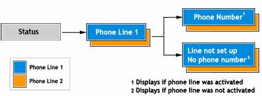
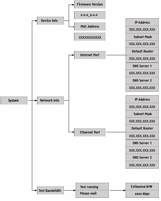
80 80
Installation guide. A. No, I do not have a router. Choose this option if you have a standard DSL or cable modem and no router.
 Installation guide This installation guide will show you how to get your voip phone service working. First, we need to know which set of instructions to give you. Please choose the option below that describes
DVG-6008S FXO VoIP Router
 This product can be set up using Internet Explorer or Netscape Navigator, 6.x or above, with Javascript enabled DVG-6008S FXO VoIP Router Before You Begin You must have at least the following: A subscription
Welcome. Unleash Your Phone
 User Manual Welcome Unleash Your Phone For assistance with installation or troubleshooting common problems, please refer to this User Manual or Quick Installation Guide. Please visit www.vonage.com/vta
Phone Adapter with Router
 Voice User Guide Model No. SPA2102 Copyright and Trademarks Specifications are subject to change without notice. Linksys is a registered trademark or trademark of Cisco Systems, Inc. and/or its affiliates
Cisco 504 IP phone. An Administrator's Guide
 Cisco 504 IP phone An Administrator's Guide Contents Introduction to Horizon... 4 SETTING UP YOUR PHONE... 5 What you ll need... 5 Assembling the phone... 5 Connecting your router... 6 Connecting the service...
Yealink W60 IP DECT phone. A guide to using your phone with Cloud Voice
 Yealink W60 IP DECT phone A guide to using your phone with Cloud Voice 2 What can this guide help you with? Make sure you can successfully call emergency services 3 1. Check out everything in the box What
Service User Manual. a service of
 Service User Manual a service of 1 The following are simple instructions and suggestions on how to better utilize your Digital Phone service from Citynet. Should you need further assistance, do not hesitate
Owning your dialtone The signature ooma dialtone is music to your ears. It means you have unlimited calling within the US with no monthly fees.
 Quick Start guide GET READY TO SAY HELLO TO: Everything you need to get started is inside this box, and everything you need to know about installation is in your hands. Don t be fooled by the size of this
UIP1868P Router Configuration Guide
 UIP868P Router Configuration Guide The UIP868P can function as your primary gateway/router or as a device client within an existing network configuration. If you currently have broadband access and a gateway/router
Cisco Model SPA 303 Quick Start Guide
 Cisco Model SPA 303 Quick Start Guide Welcome Thank you for choosing the Cisco Small Business IP phone. This guide describes how to install your phone and how to perform some basic tasks. 1 Installing
Digital Voice Services Residential User Guide
 Digital Voice Services Residential User Guide 2 P a g e * Feature Access Codes *11 Broadworks Anywhere (pulling call to alternate phone) *62 Access Voicemail *72 Call Forwarding Always Activation *73 Call
VoiceLine Calling Features
 VoiceLine Calling Features For a complete list of features and codes, refer to the VoiceLine User s Guide. VOICELINE CALLING FEATURES Feature Call Waiting Caller ID 3-Way Calling Description Once you hear
Quick Start Guide. Cisco SPA232D Mobility Enhanced ATA
 Quick Start Guide Cisco SPA232D Mobility Enhanced ATA Package Contents Analog Telephone Adapter Ethernet Cable Phone Cable Power Adapter Quick Start Guide Product CD-ROM Welcome Thank you for choosing
VoiceLine Getting Started Guide InnoMedia MTA R
 VoiceLine Getting Started Guide InnoMedia MTA 3328-2R June 2005 IMPORTANT NOTICE CONCERNING EMERGENCY 911 SERVICES Your service provider, not the manufacturer of the equipment, is responsible for the provision
Get to know your Modem 1. Modem Technical Overview 3
 User Manual Get to know your Modem 1 Modem Technical Overview 3 Managing your Modem Settings How to view your Modem settings 5 Understanding the front page 6 Changing your Modem login password 7 Upgrading
All Rights Reserved. February 2005 Version 1.1
 All Rights Reserved The use, disclosure, modification, transfer or transmittal of this work for any purpose, in any form, or by any means, without the written permission from Net2Phone is strictly forbidden.
DVG-2001S VoIP Terminal Adapter
 This product can be set up using any current web browser, i.e., Internet Explorer 6 or Netscape Navigator 6.2.3. DVG-2001S VoIP Terminal Adapter Before You Begin 1. If you purchased this VoIP Terminal
Voic Plus User Guide
 Voicemail Plus User Guide Version: 2.0_CA Revised: 25 September 2007 Notices Copyright 2007 Vonage. All rights reserved. No part of this documentation may be reproduced in any form or by any means or used
Two-Line Speakerphone with Caller ID/Call Waiting 992
 0992_CIB_1ATT_FINAL_022105 2/22/04 4:46 PM Page II User's Manual Part 2 Two-Line Speakerphone with Caller ID/Call Waiting 992 In case of difficulty, visit our Service Center at www.telephones.att.com or
2757 VoIP Phone Users Guide
 2757 VoIP Phone Users Guide Rev. 1.0 Table of Contents 1 Introduction... 5 1.1 Package Contents... 5 1.2 Features... 5 1.3 Basic Setup... 6 2 Network Setup... 8 2.1 Static IP Address... 8 2-2 PPPoE...11
Aastra 480i VoIP Telephone User s Guide
 Aastra 480i VoIP Telephone User s Guide Initial Start-Up/Restart The first time you plug in your phone and every time you restart your phone it automatically goes through the start-up process. After displaying
PowerTouch 350. User Guide
 PowerTouch 350 User Guide Contents Introduction...1 Unpacking the phone...3 Description...4 Installation...6 Installing on a desk...6 Installing on a wall...9 Checking your telephone...11 Basic features...12
Contents. Section 1 Overview 1. Section 2 Setting up your System 13
 Contents Section 1 Overview 1 Introduction 1 Installing Your System 2 Bizfon Customer Care 2 Voice Vault Card Option 2 Arranging for Telephone Company Services 3 Overview of Initial Bizfon Settings 4 Bizfon
Linksys SPA 2102 ATA Setup & Troubleshooting Guide
 Linksys SPA 2102 ATA Setup & Troubleshooting Guide Basic Setup Connecting the Telerain Linksys SPA 2102 with a router The SPA 2102 will be placed right after your DSL or Cable Modem before the router.
9417CW Installation and User Guide
 9417CW Installation and User Guide 9417CW Telephone Important Tips Wait for at least two rings to allow the phone to identify a caller and display the caller s name and/or number. You will have to subscribe
DI-704P Ethernet Broadband Router. Ethernet (Straight Through) Cable. 5V DC Power Adapter
 Cable. 5V DC Power Adapter") 1 This product can be set up using any current Web browser, i.e., Internet Explorer or Netscape Navigator. DI-704P Ethernet Broadband Router and Print Server Before You Begin 1. If you purchased this router
1 This product can be set up using any current Web browser, i.e., Internet Explorer or Netscape Navigator. DI-704P Ethernet Broadband Router and Print Server Before You Begin 1. If you purchased this router
DI-808HV 8-Port Broadband VPN Router
 This product can be set up using any current web browser, i.e., Internet Explorer 6 or Netscape Navigator 6.2.3. DI-808HV 8-Port Broadband VPN Router 1. Thank you for purchasing this Router to share your
ZTE WIRELESS HOME PHONE BASE QUICK TIP GUIDE
 ZTE WIRELESS HOME PHONE BASE QUICK TIP GUIDE INTRODUCTION Thank you for choosing Consumer Cellular! We know you re excited to use your new Wireless Home Phone Base and this short guide will help you get
Pocket User Guide 480i Phone. for Sphericall
 Pocket User Guide 480i Phone for Sphericall 480i for Sphericall User Guide Revised: May 12, 2004 Sayson Technologies Ltd. will not accept liability for any damages and/or long distance charges, which result
Part # Quick-Start Guide. SpeedStream 4200 Modem PPPoE Modem Router
 Part # 007-0-00 Quick-Start Guide SpeedStream 00 Modem PPPoE Modem Router Before you begin, Verify that the following items came with your DSL kit: Step > Install Line Filters 7 SpeedStream Device Documentation
User s manual. ML17929 Two-line corded telephone with caller ID/call waiting
 User s manual ML17929 Two-line corded telephone with caller ID/call waiting Congratulations on purchasing your new AT&T product. Before using this AT&T product, please read Important safety information
CL210A TELEPHONE & ANSWERING MACHINE
 CL210A TELEPHONE & ANSWERING MACHINE CONTENTS CONTENTS CONTENTS 1 INTRODUCTION 3 Unpacking the Telephone 4 DESCRIPTION 5 General Description 5 INSTALLATION 7 Setting Up 7 Wall Mounting 7 SETTINGS 8 Ringer
Steady green On hook. Slow flashing green Off hook. Off Port not ready. Off No link. Fast flashing green Upgrading firmware.
 Product Features Product Features Top Panel Feature Description Steady green On hook. Phone Phone 2 Slow flashing green Off hook. Off Port not ready. Flashing green Transmitting or receiving data through
Setting Up Your Cordless Desk Phone and Base Station for your OfficeSuite Phone BVNDESK10
 Setting Up Your Cordless Desk Phone and Base Station for your OfficeSuite Phone BVNDESK10 Welcome to OfficeSuite Phone Your new 100 percent cloud-based system, OfficeSuite Phone includes hundreds of advanced
A very quick guide to getting online
 A very quick guide to getting online Your quick guide to getting online Vodafone Power to you What s in the box? Vodafone modem Quick Start Guide Power Supply Ethernet cable (yellow) Ethernet cable (grey)
Nortel IP Phone 1120E User Guide
 Nortel IP Phone 1120E User Guide NN10300-022 Document status: Standard Document version: 0103 Document date: 13 April 2007 All Rights Reserved The information in this document is sourced in Canada, the
Get Started with Your New ATA
 Your New ATA, page 1 Devices Associated with Your ATA, page 5 Install Your New ATA, page 6 Mount Your ATA, page 8 Supported ATA Call Features, page 9 Your New ATA Your analog telephone adapter (ATA) allows
Paradyne Windows XP Setup Instructions. Welcome to Hay Communications High Speed Internet Service
 Paradyne Windows XP Setup Instructions Welcome to Hay Communications High Speed Internet Service The next few pages will guide you through the installation of the modem and software requirements of your
AT&T and the globe symbol are registered trademarks of AT&T Corp. licensed to Advanced American Telephones.
 1 USER S MANUAL Part 2 Tapeless Digital Answering System Telephone with Time/Day 1817 Fold open this manual for information about this telephone s installation and operation. Please also read Part 1 Important
AC1200M/MS. User Manual
 AC1200M/MS User Manual Table of Contents User Manual... 1 1 Preface... 1 2 LED Indicators and Connectors... 1 2.1 LED Indicators... 1 2.2 Hardware Installation... 2 3 Voice Prompt (AC1200MS)... 2 4 User
Virtual Office Phone Service Setup Guide
 Setup Guide A guide for the Phone System Administrator Version 4.0, July 2010 Table of Contents Welcome to 8x8 Virtual Office!...3 Activate Your 8x8 IP Phones...3 The 8x8 Self Service Portal...4 Set Up
CONTENTS. Getting connected. Ethernet Setup. Connecting a Router. Logging on. Configuring DHCP in Windows. Configuring DHCP on a Mac.
 CONTENTS 1 2 3 4 5 7 8 Getting connected Ethernet Setup Connecting a Router Logging on Configuring DHCP in Windows Configuring DHCP on a Mac Troubleshooting HELP TIP: Visit support.getwireless.net for
Issue Phone won t charge
 Issue Phone won t charge 1. Using the wrong AC ADAPTER with this phone, may cause the unit to malfunction. Make sure that you are using the AC ADAPTER that came in the box with your unit. 2. If the battery
TT11 VoIP Router 1FXS/1FXO TA User Guide
 TT11 VoIP Router 1FXS/1FXO TA User Guide Page 1 Table of Contents: 1.0 Introduction... 3 2.0 Package Contents... 3 3.0 Summary of LED & Connector Descriptions... 4 3.1 The Front LEDs... 4 3.2 The Rear
Frequently Asked Questions
 Serene CL-60 Big Button Amplified Talking CID Cordless Phone W/ Display Screen Frequently Asked Questions Q: How can I turn off the "talking" voice? A: Just set the "talking" selection switch to Off in
Virtual Office Phone Service Setup Guide
 Setup Guide A guide for the Phone System Administrator Version 6.0, November 2010 Table of Contents Welcome to 8x8 Virtual Office!...3 8x8 Virtual Office Softphone...3 Activate Your 8x8 IP Phones...3 The
Broadband Router. with 2 Phone Ports WIRED. Installation and Troubleshooting Guide RT31P2. A Division of Cisco Systems, Inc. Model No.
 A Division of Cisco Systems, Inc. Broadband Router with 2 Phone Ports WIRED Installation and Troubleshooting Guide Model No. RT31P2 Copyright and Trademarks Specifications are subject to change without
babytel Self Install Guide
 babytel Self Install Guide Last updated April 5, 2005 Contents Contents --------------------------------------------------------------------------------------------------------------------2 Welcome --------------------------------------------------------------------------------------------------------------------3
This manual covers 3Com U.S. Robotics faxmodems.
 This manual covers 3Com U.S. Robotics faxmodems. 3Com, the 3Com logo, U.S. Robotics, and Winmodem are registered trademarks and Connections, RapidComm, and x2 are trademarks of 3Com Corporation. Windows
vsuite Home Phone Feature Reference
 vsuite Home Phone Feature Reference Below is a list of features that are included with you new vsuite telephone service. Should you have any questions or problems with a feature please feel free to contact
Cisco SRP527W Router. DOT (Digital Office Technology) User Guide. Start
 User Guide. Start") Cisco SRP527W Router DOT (Digital Office Technology) User Guide Start Router (Cisco Small Business Pro SRP527W) Broadband Backup Modem (if purchased) DOT Self-Install CD Section 1. What s in the Box Router
Cisco SRP527W Router DOT (Digital Office Technology) User Guide Start Router (Cisco Small Business Pro SRP527W) Broadband Backup Modem (if purchased) DOT Self-Install CD Section 1. What s in the Box Router
LAZER Model 905K USER GUIDE
 Specification This product is designed for use in Great Britain and complies with the European Low Voltage and EMC Directives. For a copy of the Declaration of Conformity for this product, please write
HUAWEI FT2260 Home Phone Connect Quick Start
 HUAWEI FT2260 Home Phone Connect Quick Start Introduction Top View The figures are only for your reference, the actual shape and color of the product may differ slightly. 7 8 9 10 1 2 3 4 5 6 1 Power on/off
Cisco 525 IP phone. An Administrator's Guide
 Cisco 525 IP phone An Administrator's Guide Contents Introduction to Horizon... 4 SETTING UP YOUR PHONE... 5 What you ll need... 5 Assembling the phone... 5 Connecting your router... 6 Connecting the service...
BESTip ATA Combo Quick Start Manual (Ver.1.53G)
") BESTip ATA Combo Quick Start Manual (Ver.1.53G) Requirements: Before making any Internet call from your BESTip ATA Combo, you need the following items: 1. An Touch-tone phone set. 2. An 110/220V AC electrical
BESTip ATA Combo Quick Start Manual (Ver.1.53G) Requirements: Before making any Internet call from your BESTip ATA Combo, you need the following items: 1. An Touch-tone phone set. 2. An 110/220V AC electrical
Welcome to Wi-Power Digital Phone Service
 WELCOME to Welcome to Wi-Power Service Thank you for choosing Wi-Power Service! This booklet includes important information to better acquaint yourself with Wi-Power Service. Features: Wi-Power Service
InnoMedia ipbx-400. Quick Install Guide.
 InnoMedia ipbx-400 Quick Install Guide www.innomedia.com Table of Contents Introduction 2 Package Contents 2 Installation 3 Wall-Mounting Instructions 5 Troubleshooting 6 Appendix A. LED Status Summary
High Speed Internet set up guide. Read me first
 High Speed Internet set up guide Read me first Welcome Thank you for choosing TELUS. The 10 simple steps in this guide will help you set up your modem and quickly connect to the Internet. If you have questions
CORDLESS ANSWERING SYSTEM TELEPHONE 7620
 CORDLESS ANSWERING SYSTEM TELEPHONE 7620 Installation Telephone Operation Memory Answering System Operation Installation Table Installation 1. Choose a spot near an electrical outlet and a telephone jack.
Quick Installation Guide DVG-N5412SP VoIP Wireless Router
 Quick Installation Guide DVG-N5412SP VoIP Wireless Router Check Your Package Contents DVG-N5412SP VoIP Router Phone Cord X 2 Ether Cable (CAT5 UTP) 12VDC, 2A Power Adapter Using a power adapter with a
User s manual. 993 Two-line speakerphone with caller ID/call waiting
 User s manual 993 Two-line speakerphone with caller ID/call waiting Congratulations on purchasing your new AT&T product Before using this AT&T product, please read the Important product information on
AT&T. PARTNER Communications System Remote Administration Unit. Installation and Use
 AT&T PARTNER Communications System Remote Administration Unit Installation and Use Copyright 1994 AT&T All Rights Reserved Printed U.S.A. AT&T 518-455-050 Issue 1 April 1994 Notice Every effort was made
Horizon Integrator. Full user guide
 Horizon Integrator Full user guide Contents Contents... 2 Getting started... 3 Installation... 3 Signing in... 3 Introduction... 4 The basics... 5 Tray menu... 5 Phone window... 6 Preview window... 6 Making
Nortel IP Phone 1120E/1140E User Guide (CICM).
.") Nortel IP Phone 1120E/1140E User Guide (CICM). Overview Nortel IP Phone 1120E/1140E brings voice and data to the desktop by connecting directly to a Local Area Network (LAN) through an Ethernet connection.
Nortel IP Phone 1120E/1140E User Guide (CICM). Overview Nortel IP Phone 1120E/1140E brings voice and data to the desktop by connecting directly to a Local Area Network (LAN) through an Ethernet connection.
LAZER Model 906K USER GUIDE
 Specification This product is designed for use in Great Britain and complies with the European Low Voltage and EMC Directives. For a copy of the Declaration of Conformity for this product, please write
4Sight for Mac User Guide. Version 2.4
 4Sight for Mac User Guide Version 2.4 Contents Welcome to 4Sight for Mac Desktop Client... 3 How to Install 4Sight... 3 Where is it?... 4 The Dock menu... 4 The menu bar... 4 Phone window... 5 Preview
Cisco 504G, 514G, 508G, and 303G Initial Setup
 Cisco 504G, 514G, 508G, and 303G Initial Setup 1 Handset 2 Message Waiting Indicator 3 LCD Screen 4 Line keys 5 Softkey buttons 6 Navigation button 7 Messages button 8 Hold button 9 Setup button 10 Mute
9516CW Installation and User Guide
 9516CW Installation and User Guide 9516CW Important Tips Wait for at least two rings to allow the phone to identify a caller and display the caller s name and/or number. You will have to subscribe to a
Table of Contents. CRA-200 Analog Telephone Adapter 2 x Ethernet Port + 2 x VoIP Line. Quick Installation Guide. CRA-200 Quick Installation Guide
 CRA-200 Analog Telephone Adapter 2 x Ethernet Port + 2 x VoIP Line Quick Installation Guide Table of Contents VoIP ATA Package Contents... 2 Checklist... 2 IMPORTANT SAFETY INSTRUCTIONS... 3 Connecting
3G/4G Wireless N150 Router m2
 NETCOMM LIBERTY SERIES 3G/4G Wireless N150 Router m2 3GM2WN Quick Start Guide The router has been designed to be placed on a desktop. All of the cables exit from the rear for better organization. The LED
Version
 Version 1.03 5.30.12 Table of contents Introduction... 3 Welcome... 3 Installing the Cisco IP Phone... 4 Installing the Phone and Connecting to the Network... 4 Connecting Your Phone... 5 Using the Cisco
DI GHz Wireless Router
 This product can be set up using any current web browser, i.e., Internet Explorer 6 or Netscape Navigator 6.2.3. DI-514 2.4GHz Wireless Router Before You Begin 1. If you purchased this router to share
900 MHz Digital Two-Line Cordless Speakerphone with Answering System 9452 with Caller ID/Call Waiting
 USER S MANUAL Part 2 900 MHz Digital Two-Line Cordless Speakerphone with Answering System 9452 with Caller ID/Call Waiting Please also read Part 1 Important Product Information AT&T and the globe symbol
Cisco Small Business Model SPA 303g
 Cisco Small Business Model SPA 303g User Guide Version 1 Table of Contents Getting Started... 6 About This Document... 6 Organization... 7 Overview of the Cisco Small Business 300 Series IP Phones... 8
User Guide: Panasonic KX-UT113
 User Guide: Panasonic KX-UT113 User Guide Contents: User Guide Contents:... 2 KX-UT113 Button Diagram... 3 Telephone Feature Overview... 4 KX-UT113 Features... 4 Reading the Display... 4 How to Use your
4-Port Router. Share your broadband Internet connection. E Wired. Ethernet. Ethernet. User Manual. F5D5231-4_uk
 4-Port Router Share your broadband Internet connection User Manual E Wired Ethernet Ethernet 10/100 Mbps F5D5231-4_uk Table of Contents 1 Introduction............................................. 1 Benefits
Four-Line Intercom/ Speakerphone 954
 1 USER S MANUAL Part 2 Four-Line Intercom/ Speakerphone 954 Please also read Part 1 Important Product Information AT&T and the globe symbol are registered trademarks of AT&T Corp. licensed to Advanced
BT Duet 210. User Guide
 BT Duet 210 User Guide Welcome. to your BT Duet 210 Corded Telephone 10 number quickdial memory - for ease of dialling your most important telephone numbers Mute mutes your voice so you can talk to someone
Xchange for Samsung MAC User Guide. Version 2.4
 Xchange for Samsung MAC User Guide Version 2.4 Contents Welcome to Xchange for Samsung Mac Desktop Client... 32 How to Install Xchange... 3 Where is it?... 43 The Dock menu... 4 The menu bar... 4 Preview
User s Manual ADSL Router Modem DB Ethernet Ports
 User s Manual ADSL Router Modem DB 120 4 Ethernet Ports 1. About ADSL ADSL (Asymmetric Digital Subscriber Line) is a technology that allows high-speed data to be transmitted over existing copper telephone
Cisco Small Business Model SPA 504g
 Cisco Small Business Model SPA 504g User Guide Version 1 Table of Contents Getting Started... 1 About This Document... 1 Organization... 1 Overview of the Cisco Small Business IP Phones... 3 Understanding
DSL-504T ADSL Router. CD-ROM (containing User Manual) Ethernet Cable (CAT5 UTP) ADSL Cable (For AUS 200CM) Power Adapter
 Ethernet Cable (CAT5 UTP) ADSL Cable (For AUS 200CM) Power Adapter") This product can be set up using any current web browser, i.e., Internet Explorer 6 or Netscape Navigator 6.2.3. DSL-504T ADSL Router Before You Begin 1. If you purchased this Router to share your high-speed
This product can be set up using any current web browser, i.e., Internet Explorer 6 or Netscape Navigator 6.2.3. DSL-504T ADSL Router Before You Begin 1. If you purchased this Router to share your high-speed
User Guide. Linksys X-Series. Wireless Router with ADSL2+ Modem
 User Guide Linksys X-Series Wireless Router with ADSL2+ Modem Contents Contents Product Overview X1000..................................... 1 Top 1 Back 1 Wall-mounting placement 2 X3500.....................................
CONTENTS. Getting connected. Ethernet Setup. Connecting a Router. Logging on. Configuring DHCP in Windows. Configuring DHCP on a Mac.
 Username: Password: CONTENTS 1 2 3 4 5 7 8 Getting connected Ethernet Setup Connecting a Router Logging on Configuring DHCP in Windows Configuring DHCP on a Mac Troubleshooting HELP TIP: Visit dojonetworks.com/support
Cisco SRP500 Series Services Ready Platforms (SRP540 Models)
") Quick Start Guide Cisco SRP500 Series Services Ready Platforms (SRP540 Models) Package Contents Cisco SRP500 Series (with detachable WiFi antennas) RJ-45 Ethernet Cable RJ-11 Telephone Cable Power Cord
Quick Start Guide Cisco SRP500 Series Services Ready Platforms (SRP540 Models) Package Contents Cisco SRP500 Series (with detachable WiFi antennas) RJ-45 Ethernet Cable RJ-11 Telephone Cable Power Cord
DSL Quick-Install Guide
 DSL Quick-Install Guide Last Update: April 22, 2008 - 2 - Welcome and Introduction... 4 Setting Up Your DSL Modem... 5 Step 1 (Check Equipment)... 5 Step 2 (Install Inline Micro-Filters)... 5 Step 3 (ADSL
Welcome! Please review before beginning your installation.
 AT&T High Speed Internet Service Self-Installation Guide for Modem Equipment Welcome! Please review before beginning your installation. 12 Have you checked your Service Activation date and time? You can
Voice Cable Modem User Manual
 User Manual Model CM500V September 2017 202-11792-01 350 E. Plumeria Drive San Jose, CA 95134 USA Support Thank you for purchasing this NETGEAR product. You can visit www.netgear.com/support to register
Welcome to our self-diagnosis guide. Your offline interactive assistant for Telkom s fixed voice and Broadband services.
 Welcome to our self-diagnosis guide. Your offline interactive assistant for Telkom s fixed voice and Broadband services. This tool was built to help you resolve the most common faults encountered when
WIRELESS ROUTER N150. User Manual. F9K1009v1 8820zb01125 Rev.B00
 WIRELESS ROUTER N150 User Manual F9K1009v1 8820zb01125 Rev.B00 TABLE OF CONTENTS Getting Started... 1 What s in the Box...1 Initial Setup...1 How to Set It UP...2 Adding Computers to Your Network...3 Manually
Polycom VVX 500 and 601. A guide to using your phone with Cloud Phone.
 Polycom VVX 500 and 601 A guide to using your phone with Cloud Phone. 2 What s in this guide What s in the box 3 Got everything? 3 Let s get started 4 Set your phone up 4 Get connected 4 Check you re connected
Part # Quick-Start Guide. SpeedStream 6500 Residential Gateway
 Part # 007-6510-001 Quick-Start Guide SpeedStream 6500 Residential Gateway Before you begin, Verify that the following items came with your DSL kit: Step 1 > Install Line Filters 1 2 4 5 6 1 SpeedStream
Ethernet (CAT5 UTP/Straight-Through) Cable. 5V DC Power Adapter
 Cable. 5V DC Power Adapter") 1 This product can be set up using any current web browser, i.e., Internet Explorer 6 or Netscape Navigator 6.2.3. Before You Begin Check Your Package Contents DI-824VUP+ 2.4GHz Wireless VPN Router and
1 This product can be set up using any current web browser, i.e., Internet Explorer 6 or Netscape Navigator 6.2.3. Before You Begin Check Your Package Contents DI-824VUP+ 2.4GHz Wireless VPN Router and
Cisco Model SPA 525G Quick Start Guide
 Cisco Model SPA 525G Quick Start Guide Welcome Thank you for choosing the Cisco Small Business IP phone. This guide describes how to install your phone and how to perform some basic tasks. 1 Installing
BT One Phone. Yealink SIP-T40 phone user guide
 BT One Phone Yealink SIP-T40 user guide 2 What s in this guide Need help? If you have any problems setting up or using your Yealink IP Phone, contact BT One Phone helpdesk on 0845 154 8844 (or 8844 from
Congratulations! Installation Connecting the telephone Features: Caller ID service Setting Clock (Date and Time)
") Congratulations! You are now the owner of a VEF&CO Phone telephone set, a quality communications product. To ensure trouble-free operation, please read these instructions carefully before beginning installation.
Congratulations! You are now the owner of a VEF&CO Phone telephone set, a quality communications product. To ensure trouble-free operation, please read these instructions carefully before beginning installation.
InnoMedia ESBC B. Quick Install Guide. 1
 InnoMedia ESBC 9380-4B Quick Install Guide www.innomedia.com 1 Table of Contents Introduction 3 Package Contents 3 CAUTION 3 Installation 4 Wall-Mounting Instructions 6 Troubleshooting 7 Appendix A. LED
Vodafone Business Phone User Guide
 Vodafone Business Phone User Guide Contents 1. VODAFONE CALLING FEATURES 4 1.1 Inclusive Calling Features 4 Find out who s called you 4 Hiding your phone number 4 1.2 Optional Calling Features 5 Call Divert
Digital Telephone User Guide
 Digital Telephone User Guide 1 P. O. Box 99, Conway, AR 72033 (501) 450-6000 ConwayCorp.com * Feature Access Codes *11 Broadworks Anywhere (pulling call to alternate phone) *62 Access Voicemail *72 Call
3300 IP Communications Platform
 MITEL 3300 IP Communications Platform ACD Agent Guide for the Mitel 5224 and 5324 IP Phones NOTICE The information contained in this document is believed to be accurate in all respects but is not warranted