USER S MANUAL. Hi-Gain Wireless-AC Multi-Function Access Point/Bridge. website
|
|
|
- Ralf Harmon
- 6 years ago
- Views:
Transcription
1 Hi-Gain Wireless-AC Multi-Function Access Point/Bridge HW7ACB website USER S MANUAL COPYRIGHT 2014 HAWKING TECHNOLOGIES,INC. ALL RIGHTS RESERVED.
2 COPYRIGHT Copyright 2014 by Hawking Technologies. All rights reserved. No part of this publication may be reproduced, transmitted, transcribed, stored in a retrieval system, or translated into any language or computer language, in any form or by any means, electronic, mechanical, magnetic, optical, chemical, manual or otherwise, without the prior written permission of this company Hawking Technologies makes no representations or warranties, either expressed or implied, with respect to the contents hereof and specifically disclaims any warranties, merchantability or fitness for any particular purpose. Any software described in this manual is sold or licensed "as is". Should the programs prove defective following their purchase, the buyer (and not Hawking Technologies, its distributor, or its dealer) assumes the entire cost of all necessary servicing, repair, and any incidental or consequential damages resulting from any defect in the software. Further, this company reserves the right to revise this publication and to make changes from time to time in the contents thereof without obligation to notify any person of such revision or changes.
3 Federal Communication Commission Interference Statement FCC Part 15 This equipment has been tested and found to comply with the limits for a Class B digital device, pursuant to Part 15 of FCC Rules. These limits are designed to provide reasonable protection against harmful interference in a residential installation. This equipment generates, uses, and can radiate radio frequency energy and, if not installed and used in accordance with the instructions, may cause harmful interference to radio communications. However, there is no guarantee that interference will not occur in a particular installation. If this equipment does cause harmful interference to radio or television reception, which can be determined by turning the equipment off and on, the user is encouraged to try to correct the interference by one or more of the following measures: 1. Reorient or relocate the receiving antenna. 2. Increase the separation between the equipment and receiver. 3. Connect the equipment into an outlet on a circuit different from that to which the receiver is connected. 4. Consult the dealer or an experienced radio technician for help. FCC Caution This equipment must be installed and operated in accordance with provided instructions and a minimum 20 cm spacing must be provided between computer mounted antenna and person s body (excluding extremities of hands, wrist and feet) during wireless modes of operation. This device complies with Part 15 of the FCC Rules. Operation is subject to the following two conditions: (1) this device may not cause harmful interference, and (2) this device must accept any interference received, including interference that may cause undesired operation.
4 Any changes or modifications not expressly approved by the party responsible for compliance could void the authority to operate equipment. Federal Communication Commission (FCC) Radiation Exposure Statement This equipment complies with FCC radiation exposure set forth for an uncontrolled environment. In order to avoid the possibility of exceeding the FCC radio frequency exposure limits, human proximity to the antenna shall not be less than 20cm (8 inches) during normal operation. The antenna(s) used for this transmitter must not be co-located or operating in conjunction with any other antenna or transmitter.
5 R&TTE Compliance Statement This equipment complies with all the requirements of DIRECTIVE 1999/5/EC OF THE EUROPEAN PARLIAMENT AND THE COUNCIL of March 9, 1999 on radio equipment and telecommunication terminal Equipment and the mutual recognition of their conformity (R&TTE). The R&TTE Directive repeals and replaces in the directive 98/13/EEC (Telecommunications Terminal Equipment and Satellite Earth Station Equipment) As of April 8, Safety This equipment is designed with the utmost care for the safety of those who install and use it. However, special attention must be paid to the dangers of electric shock and static electricity when working with electrical equipment. All guidelines of this and of the computer manufacture must therefore be allowed at all times to ensure the safe use of the equipment. EU Countries Intended for Use The ETSI version of this device is intended for home and office use in Austria, Belgium, Denmark, Finland, France, Germany, Greece, Ireland, Italy, Luxembourg, the Netherlands, Portugal, Spain, Sweden, and the United Kingdom. The ETSI version of this device is also authorized for use in EFTA member states: Iceland, Liechtenstein, Norway, and Switzerland. EU Countries Not intended for use None.
6 CONTENTS Chapter I: Product Information Product Introduction Safety Information System Requirements Package Contents Product Overview... 6 Chapter II: Quick Setup and Basic Settings Installing the HW7ACB Connecting to the HW7ACB by Web Browser Windows 95/98/Me IP Address Setup: Windows 2000 IP Address Setup Windows XP IP Address Setup Windows Vista/7/8 IP Address Setup Mac OS X IP Address Setup Tablet/Smartphone Setup Connecting to Web Management Interface Quick Setup Setup Procedure for Router Setup Procedure for Access Point Setup Procedure Bridge Setup procedure for Bridge-Point to Point : Setup procedure for Bridge-Point to Multi-Point Setup Procedure for Bridge WDS Chapter III General Setup Time zone and time auto-synchronization Change Management password Remote Management Setup Internet Connection (WAN Setup) Setup Procedure for Dynamic IP : Setup Procedure for Static IP : Setup Procedure for PPPoE : Setup Procedure for DNS : Setup Procedure for DDNS : Wired LAN Configuration Local Network... 72
7 3-5-2 DHCP Server: Static DHCP Leases Table: Wireless Network Basic Wireless Settings Access Point Bridge (Station Infrastructure) AP Bridge-Point to Point AP Bridge-Point to Multi-Point AP Bridge-WDS Advanced Wireless Settings Security Settings Disable wireless security WEP - Wired Equivalent Privacy Wi-Fi Protected Access (WPA): WPA RADIUS: Wireless Access Control Wi-Fi Protected Setup (WPS) Security Tips for Wireless Network Quality of Service (QoS) Basic QoS Settings Add a new QoS rule Network Address Translation (NAT) Basic NAT Settings (Enable or disable NAT function) Port Forwarding Virtual Server Port Mapping for Special Applications UPnP Setting ALG Settings Firewall Access Control Add PC URL Blocking DoS Attack Prevention DoS - Advanced Settings Demilitarized Zone (DMZ) Chapter IV Status and Tools
8 4-1 System Status System information and firmware version Internet Connection Status Home Network System Log Security Log Active DHCP client list Statistics Configuration Tools Firmware Upgrade Reboot Chapter V: Appendix Hardware Specification Troubleshooting Glossary
9 Chapter I: Product Information 1-1 Product Introduction Thank you for purchasing the Hawking HW7ACB Hi-Gain Wireless-AC Multi-Function Access Point/Bridge! Easy installation procedures allow any computer user to setup a network in very short time - within minutes, even inexperienced users. Just follow the instructions given in this user manual, you can complete the setup procedure and unleash the power of this HW7ACB all by yourself! Other features of the Hi-Gain Wireless-AC Multi-Function Access Point/Bridge include: 6 different Wireless Modes: Router, Access Point, Bridge Client, Bridge Point to Point, Bridge Point to Multi-Point and AP Bridge WDS modes Supports 2.4GHz and 5GHz wireless devices simultaneously. Provides IEEE A/B/G/N/AC wireless LAN capability Supports 64/128-bit WEP, WPA, and WPA2 wireless data encryption. Supports MAC address filtering (Only allow specific wireless device of your choice to connect to this access point). Four wired LAN ports (10/100M) Auto MDI / MDI-X function for all wired Ethernet ports. Support DHCP (Server/Client) for easy IP-address setup. Allows you to monitor the access point s status: DHCP Client Log, System Log, Security Log and Device/Connection Status. Easy to use Web-based GUI for network configuration and management purposes. 2
10 1-2 Safety Information In order to keep the safety of users and your properties, please follow the following safety instructions: 1. This HW7ACB is designed for indoor use only; DO NOT place this HW7ACB outdoors. 2. DO NOT put this HW7ACB near hot or humid places, like a kitchen or bathroom. Also, do not leave this HW7ACB in the car. 3. DO NOT pull any connected cable with force; disconnect it from the HW7ACB first. 4. If you want to place this HW7ACB at high places or hang on the wall, please make sure the HW7ACB is firmly secured. Falling from high places would damage the HW7ACB and its accessories, and void the warranty. 5. Accessories of this HW7ACB, like the antenna and power supply, are dangerous to small children under 3 years old. They may put the small parts in their nose or mouth and it could cause serious damage to them. KEEP THIS HW7ACB OUT THE REACH OF CHILDREN! 6. The HW7ACB will become hot when being used for a long time (This is normal and is not a malfunction). DO NOT put this HW7ACB on paper, cloth, or other flammable materials. 7. There s no user-serviceable part inside the HW7ACB. If you found that the HW7ACB is not working properly, please contact your dealer of purchase and ask for help. DO NOT disassemble the HW7ACB, or the warranty will be void. 8. If the HW7ACB falls into water when it s powered, DO NOT use your hand to pick it up. Switch the electrical power off before you do anything, or contact an experienced electrical technician for help. 9. If you smell something strange or even see some smoke coming out from the HW7ACB or power supply, remove the power supply or switch the electrical power off immediately, and call dealer of purchase for help. 3
11 1-3 System Requirements Computer or network device(s) with wired or wireless network interface card. Web browser (Microsoft Internet Explorer 4.0 or above, Netscape Navigator 4.7 or above, Opera web browser, Mozilla Firefox web browser or Safari web browser). An available AC power socket ( V, 50/60Hz) 4
12 1-4 Package Contents Before you start to use this HW7ACB, please check if there is anything missing in the package. Contact your place of purchase to claim missing items: 1x HW7ACB Hi-Gain Wireless-AC Multi-Function Access/Point Bridge 1x - Quick Installation Guide 1x - A/C power adapter 1x - Ethernet cord 1x - Setup CD 5
.")
.")
13 1-5 Product Overview Top Panel LED Name Light Status Description PWR On Router is switched on and correctly powered. Wireless On Wireless is enabled. Off Wireless network is switched off. Flashing Wireless LAN activity (transferring or receiving data). WAN On WAN Port is connected Off WAN Port is not connected Flashing WAN activity (transferring or receiving data). Wired 1-4 On LAN port is linked in 10/100Mbps speed. 10/100M Off LAN port is not linked in 10/100Mbps speed. Flashing LAN activity (transferring or receiving data). Back Panel Item Name Antenna Power (12V/0.5A) Description Two 3dBi antennas Power connector, connects to A/C power adapter. 6
14 Network 1-4 WAN Reset/WPS Local Area Network (LAN) port Modem / Internet Port Reset the router to factory default settings (clear all settings) or start WPS function. Press this button and hold for 15 seconds to restore all settings to factory defaults, power off/on. Press this button for less than 5 seconds to start WPS function. NOTE: For 2.4GHz b and g mode, the signals can be transmitted only by antenna 1 (The antenna on the right side of the rear panel). For 2.4 GHz/5GHz n mode: The extender is operating in a 2T2R Spatial Multiplexing MIMO configuration. Two (2) antennas are for signal transmitting and two (2) antennas are for signal receiving. 7
15 Chapter II: Quick Setup and Basic Settings 2-1 Installing the HW7ACB Complete the following instructions to build the network connection between your new wireless HW7ACB and your computers or network devices: 1. Connect the HW7ACB to your computer (source) through the LAN port of the HW7ACB by Ethernet cable or connect to it wirelessly. 2. Connect the A/C power adapter to the wall socket, and then connect it to the Power socket of the HW7ACB. 3. Please check all LEDs on the front panel. LAN LEDs should be on if the HW7ACB is correctly connected to the router. If it is not on, or any LED you expect is not on, please recheck the cabling, or jump to 5-2 Troubleshooting for possible reasons and solutions. 8
16 2-2 Connecting to the HW7ACB by Web Browser After your HW7ACB Hi-Gain Wireless-AC Multi-Function Access Point / Bridge has been connected and powered the next step is to access the Web Menu for initial configuration. To do this, your computer must be able to get an IP address automatically (use dynamic IP address setting). Try to access: If the Web Menu appears you can skip the next steps and go to step 2-3. You will need to enter the following default login and password to access the Quick Setup menu: Login: admin Password: 1234 If it s set to use a static IP address or you are unsure, please follow the following instructions to configure your computer to use a dynamic IP address: Note: Please be sure to set your network IP addresses back to default after you have finished configuration. If the operating system of your computer is. Windows 95/98/Me - please go to section Windows please go to section Windows XP - please go to section Windows Vista/7 - please go to section Mac OS X - please go to section

17 2-2-1 Windows 95/98/Me IP Address Setup: 1. Click Start button (it should be located at lower-left corner of your computer), then click control panel. Double-click Network icon, and Network window will appear. Select TCP/IP, then click Properties. 2. Select Obtain an IP address from a DHCP server and then click OK. 10
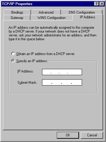
18 11
 and then click Properties 2.")
19 2-2-2 Windows 2000 IP Address Setup 1. Click Start button (it should be located at lower-left corner of your computer), then click control panel. Double-click Network and Dial-up Connections icon; click Local Area Connection, and Local Area Connection Properties window will appear. Select Internet Protocol (TCP/IP) and then click Properties 2. Select Obtain an IP address automatically and Obtain DNS server address automatically, then click OK. 12
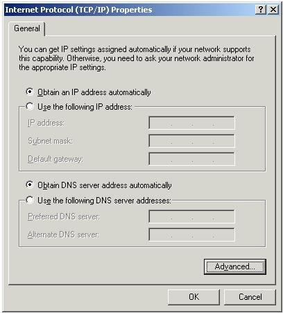
20 13

21 2-2-3 Windows XP IP Address Setup 1. Click Start button (it should be located at lower-left corner of your computer), then click control panel. Double-click Network and Internet Connections icon, click Network Connections, and then double-click Local Area Connection, Local Area Connection Status window will appear, and then click Properties 2. Select Obtain an IP address automatically and Obtain DNS server address automatically, then click OK. 14
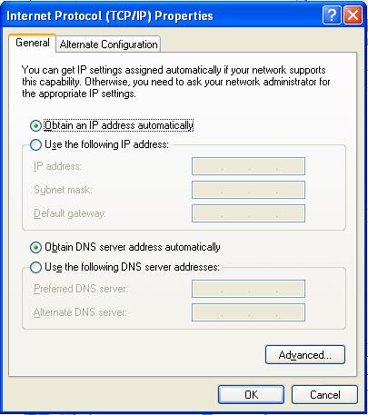
22 15

23 2-2-4 Windows Vista/7/8 IP Address Setup 1. Click Start button (it should be located at lower-left corner of your computer), then click control panel. Under Network and Internet, Click View Network Status and Tasks, then click Manage Network Connections/Change Adapter Settings on the right hand column. Right-click Local Area Network, then select Properties. Local Area Connection Properties window will appear, select Internet Protocol Version 4 (TCP / IPv4), and then click Properties 2. Select Obtain an IP address automatically and Obtain DNS server address automatically, then click OK. 16
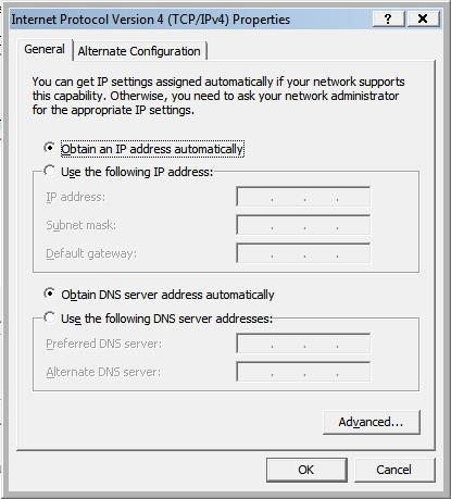
24 17

25 2-2-5 Mac OS X IP Address Setup Go to your system preferences, go to network. Select your network connection. Make sure Configure is set to Using DHCP. 18
 Hawking_HW7ACB_2.4GHz > (d) Make sure your Wi-Fi is connected to Hawking_HW7ACB_2.4GHz Android (Android 2.")
26 2-2-6 Tablet/Smartphone Setup ios (iphone or ipad) Go to your settings on your tablet or smart phone First, make sure JavaScript is On: Go to Settings icon Select (a) Safari > make sure (b) JavaScript is ON. Go back to Home Screen > Select Settings > In Wi-Fi Networks, select (c) Hawking_HW7ACB_2.4GHz > (d) Make sure your Wi-Fi is connected to Hawking_HW7ACB_2.4GHz Android (Android 2.1 +) Go to Settings 19


27 Go to Wireless & Networks Check Turn on Wi-Fi and then click on Wi-Fi settings Look for Hawking_HW7ACB_2.4GHz, then select to connect 20
28 2-2-7 Connecting to Web Management Interface All functions and settings of this HW7ACB can be configured via web management interface. Please start your web browser, and input in address bar, then press the Enter key. The following message should be shown: Please input user name and password in the fields respectively, default user name is admin, and default password is 1234, then press the OK button, and you will see the web management interface of this HW7ACB: 21

29 NOTE: If you can t see the web management interface, and you are being prompted to input the user name and password again, it means you didn t input the username and password correctly. Retype the user name and password again. If you re certain about the username and password you typed are correct, please go to 6-2 Troubleshooting to perform a factory reset. 22

30 2-3 Quick Setup This HW7ACB provides a Quick Setup procedure, which will help you to complete all required settings you need to access the Internet in very short time. Please follow the following instructions to complete the Quick Setup : Please go to Quick Setup Wizard menu by clicking Quick Setup button. 23
31 On this page, please select the mode you wish to use. There are 6 modes that the HW7ACB supports: Router - Please go to section Access Point - Please go to section Bridge - Please go to section Bridge Point to Point - Please go to section Bridge Point to Multi-Point - Please go to section WDS - Please go to section If you re not sure, please contact your network administrator. Choosing a wrong mode will cause wireless and network issues. 24
32 2-3-1 Setup Procedure for Router Choose your Time Zone. This is used for system and security logs. Click Next 25
33 On this page, choose your Internet Service Provider Type. Most users use Dynamic IP. If you use the other modes, please make sure you have your Internet Provider s supplied information to input your Static IP or user accounts for PPPoE For Dynamic, you may need to input a Host Name and/or Clone Mac Address. Most users do not need to do these steps. If you use static or PPPoE, please refer to section and Click Next, otherwise, input the information as provided by your ISP. Input the Wireless Settings you wish to use in Router Mode. The device transmits in both 2.4GHz and 5GHz. Note that if your client is ONLY 2.4GHz, it will not see the 5GHz signal. 26
34 To add wireless security for your local/home wireless network, enter an alphanumerical password (8 characters or more) below (If you do not wish to use a password, leave the field blank and click 'Next'). Users signing on to your home wireless network will be required to enter this password to connect to the internet. Click Next when done Settings are saved. you have set up the device as a router! Please click Finish and the device will reboot. Congratulations, 27
35 2-3-2 Setup Procedure for Access Point 28
 for each frequency here. You can input up to 32 alphanumerical characters. PLEASE NOTE THAT ESSID IS CASE SENSITIVE.")
36 Wireless (1): Shows you if the wireless is enabled/disabled ESSID (2): The HW7ACB transmits in both 2.4GHz and 5GHz WiFi frequencies. Please input the ESSID (the name used to identify this wireless access point) for each frequency here. You can input up to 32 alphanumerical characters. PLEASE NOTE THAT ESSID IS CASE SENSITIVE. Default SSID 2.4GHz: Hawking_HW7ACB_2.4GHz 5GHz: Hawking_HW7ACB_5GHz Band (3): Please select the wireless band you wish to use. By selecting different band setting, you ll be able to allow or deny the wireless client of a certain band. 29
37 2.4GHz Band If you select 2.4GHz (B), 2.4GHz (N), or 2.4GHz (G), only wireless clients using the wireless band you select (802.11b, Draft-N, or g) will be able to connect to this access point. If you select 2.4GHz (B+G), then only wireless clients using b and g band will be able to connect to this access point. If you want to allow b, g, and Draft-N clients to connect to this access point, select 2.4GHz (B+G+N). 5GHz Band 5GHz (A): this mode allows a wireless network client to connect this router (maximum transfer rate 54Mbps for a clients). 5GHz (N): this mode allows n wireless network client to connect this router (maximum transfer rate 300Mbps for n clients). 5GHz (A+N): this mode allows a and n wireless network client to connect this router (maximum transfer rate 54Mbps for a clients, and maximum 300Mbps for n clients). 5GHz (AC): this mode allows ac wireless network client to connect this router (maximum transfer rate 433Mbps for ac clients). 5GHz (N+AC): this mode allows n and ac wireless network client to connect this router (maximum transfer rate 150Mbps for n clients, and maximum 433Mbps for ac clients). 30
38 5GHz (A+N+AC): this mode allows a, n and ac wireless network client to connect this router (maximum transfer rate 54Mbps for a clients, maximum 150Mbps for n clients, and maximum 433Mbps for ac clients). Channel Number (4): Please select a channel number you wish to use. If you know a certain channel number is being used by other wireless access points nearby, please refrain from using the same channel number Associated Clients (5): Click Show Active Clients button and a new popup window will appear which contains the information about all wireless clients connected to this access point. You can click Refresh button in popup window to keep information up-to-date. Adv. IP Address (6) This section allows you to set an IP Address and subnet mask to fit your network if needed. Uncheck the box to input. Otherwise, the default IP Address is After you finish with all settings, please click Next (7) button. 31

39 If you wish to have security, please select your level of security here. Refer to Section for descriptions of security types. Click Apply for the device to restart. Click Back if you wish to make changes. Plug the HW7ACB into your router or network. Congratulations, you have set up the HW7ACB in Access Point! 32

40 2-3-3 Setup Procedure Bridge

41 Main ESSID (1): The wireless name of the network you wish to bridge to. Site Survey (2): When you select bridge mode, you have to associate it with a working access point. Click Select Site Survey, a Wireless Site Survey Table will pop up and list all available access points nearby. Select one access point in the table and it will join wireless LAN through this access point. Note: The HW7ACB will only repeat a 2.4GHz or a 5GHz network. Adv. IP Address (4) This section allows you to set an IP Address and subnet mask to fit your network if needed. Uncheck the box to input. Otherwise, the default IP Address is If the network you selected was a secure network, a password field will appear under the 34
42 site survey. Please enter the wireless password here. When you finish with all settings, press Next. Click Apply for the device to restart. Click Back if you wish to make changes. Plug the deivces that wish to use this as a Bridge. Congratulations, you have set up the HW7ACB as a Bridge! 35

43 2-3-4 Setup procedure for Bridge-Point to Point : 36
, 2.4GHz (N), or 2.4GHz (G), only wireless clients using the wireless band you select (802.11b, 802.11 Draft-N, or 802.11g) will be able to connect to this access point. If you select 2.")
44 Band (2): Please select the wireless band you wish to use. By selecting different band setting, you ll be able to allow or deny the wireless client of a certain band. 2.4GHz Band If you select 2.4GHz (B), 2.4GHz (N), or 2.4GHz (G), only wireless clients using the wireless band you select (802.11b, Draft-N, or g) will be able to connect to this access point. If you select 2.4GHz (B+G), then only wireless clients using b and g band will be able to connect to this access point. 37
45 If you want to allow b, g, and Draft-N clients to connect to this access point, select 2.4GHz (B+G+N). 5GHz Band 5GHz (A): this mode allows a wireless network client to connect this router (maximum transfer rate 54Mbps for a clients). 5GHz (N): this mode allows n wireless network client to connect this router (maximum transfer rate 300Mbps for n clients). 5GHz (A+N): this mode allows a and n wireless network client to connect this router (maximum transfer rate 54Mbps for a clients, and maximum 300Mbps for n clients). 5GHz (AC): this mode allows ac wireless network client to connect this router (maximum transfer rate 433Mbps for ac clients). 5GHz (N+AC): this mode allows n and ac wireless network client to connect this router (maximum transfer rate 150Mbps for n clients, and maximum 433Mbps for ac clients). 5GHz (A+N+AC): this mode allows a, n and ac wireless network client to connect this router (maximum transfer rate 54Mbps for a clients, maximum 150Mbps for n clients, and maximum 433Mbps for ac clients). Channel Number (3): Please select a channel number you wish to use. Please note that this should be the same channel as the other bridge you 38
46 wish to connect to. Device Mac Address (4): This is the Mac Address of the current HW7ACB. Use this for reference when you set up the other point to point devices. Mac Address Field (5): Input the other Mac Addresses for point to point. Note that point to point mode only works with another HW7ACB Adv. IP Address (6) This section allows you to set an IP Address and subnet mask to fit your network if needed. Uncheck the box to input. Otherwise, the default IP Address is When you finish with all settings, please click Next (7); The next page lets you set up security. Note that each HW7ACB setup in point to point mode must have the same type of security. Click Apply and wait for the unit to reboot. Plug in the devices that you wish to bridge. Congratulations, you have set up the HW7ACB in Bridge-Point to Point! 39
47 40

48 2-3-5 Setup procedure for Bridge-Point to Multi-Point 41
, 2.4GHz (N), or 2.")
49 Band (2): Please select the wireless band you wish to use. By selecting different band setting, you ll be able to allow or deny the wireless client of a certain band. 2.4GHz Band If you select 2.4GHz (B), 2.4GHz (N), or 2.4GHz (G), only wireless clients using the wireless band you select (802.11b, 42
50 Draft-N, or g) will be able to connect to this access point. If you select 2.4GHz (B+G), then only wireless clients using b and g band will be able to connect to this access point. If you want to allow b, g, and Draft-N clients to connect to this access point, select 2.4GHz (B+G+N). 5GHz Band 5GHz (A): this mode allows a wireless network client to connect this router (maximum transfer rate 54Mbps for a clients). 5GHz (N): this mode allows n wireless network client to connect this router (maximum transfer rate 300Mbps for n clients). 5GHz (A+N): this mode allows a and n wireless network client to connect this router (maximum transfer rate 54Mbps for a clients, and maximum 300Mbps for n clients). 5GHz (AC): this mode allows ac wireless network client to connect this router (maximum transfer rate 433Mbps for ac clients). 5GHz (N+AC): this mode allows n and ac wireless network client to connect this router (maximum transfer rate 150Mbps for n clients, and maximum 433Mbps for ac clients). 5GHz (A+N+AC): this mode allows a, n and ac wireless network client to connect this router (maximum transfer rate 54Mbps for a clients, maximum 43
51 150Mbps for n clients, and maximum 433Mbps for ac clients). Channel Number (3): Please select a channel number you wish to use. Please note that this should be the same channel as the other bridge you wish to connect to. Device Mac Address (4): This is the Mac Address of the current HW7ACB. Use this for reference when you set up the other point to point devices. Mac Address Field (5): Input the other Mac Addresses for point to point. Note that point to muliti-point mode only works with up to 4 other HW7ACBs. Adv. IP Address (6) This section allows you to set an IP Address and subnet mask to fit your network if needed. Uncheck the box to input. Otherwise, the default IP Address is When you finish with all settings, please click Next (7); The next page lets you set up security. Note that each HW7ACB setup in point to point mode must have the same type of security. 44
52 Click Apply and wait for the unit to reboot. Plug in the devices that you wish to bridge. Congratulations, you have set up the HW7ACB in Bridge Point to Multi Point! 45
53 2-3-6 Setup Procedure for Bridge WDS 46
, 2.4GHz (N), or 2.")
54 Wireless (1): Shows you if the wireless is enabled/disabled Band (2): 2.4GHz Band If you select 2.4GHz (B), 2.4GHz (N), or 2.4GHz (G), only wireless clients using the wireless band you select (802.11b, 47
55 Draft-N, or g) will be able to connect to this access point. If you select 2.4GHz (B+G), then only wireless clients using b and g band will be able to connect to this access point. If you want to allow b, g, and Draft-N clients to connect to this access point, select 2.4GHz (B+G+N). 5GHz Band 5GHz (A): this mode allows a wireless network client to connect this router (maximum transfer rate 54Mbps for a clients). 5GHz (N): this mode allows n wireless network client to connect this router (maximum transfer rate 300Mbps for n clients). 5GHz (A+N): this mode allows a and n wireless network client to connect this router (maximum transfer rate 54Mbps for a clients, and maximum 300Mbps for n clients). 5GHz (AC): this mode allows ac wireless network client to connect this router (maximum transfer rate 433Mbps for ac clients). 5GHz (N+AC): this mode allows n and ac wireless network client to connect this router (maximum transfer rate 150Mbps for n clients, and maximum 433Mbps for ac clients). 5GHz (A+N+AC): this mode allows a, n and ac wireless network client to connect this router (maximum transfer rate 54Mbps for a clients, maximum 48
56 150Mbps for n clients, and maximum 433Mbps for ac clients). SSID (3): Please input the ESSID (the name used to identify this wireless access point) here. You can input up to 32 alphanumerical characters. PLEASE NOTE THAT ESSID IS CASE SENSITIVE. Note that all other devices in the WDS mode should use the same SSID. Channel Number (4): Please select a channel number you wish to use. Please note that this should be the same channel as the other bridge you wish to connect to. Device Mac Address (5): This is the Mac Address of the current HW7ACB. Use this for reference when you set up the other point to point devices. Mac Address Field (6): Input the other Mac Addresses for point to point. Note that wds mode only works with up to 4 other HW7ACBs. Adv. IP Address (7) This section allows you to set an IP Address and subnet mask to fit your network if needed. Uncheck the box to input. Otherwise, the default IP Address is When you finish with all settings, please click Next (8); The next page lets you set up security. Note that each HW7ACB setup in wds mode must have the same type of security. 49

57 Click Apply and wait for the unit to reboot. HW7ACB in WDS Mode! Congratulations, you have set up the 50

58 Chapter III General Setup In this chapter, you ll know how to change the major settings of the HW7ACB. Log onto the device and click on General Setup. 51
59 3-1 Time zone and time auto-synchronization Please follow the following instructions to set time zone and time auto-synchronization parameters: Please click General Setup at the top of web management interface, select System on the left hand column, and select Time Zone. The time zone settings will be displayed in your web browser: Please select the correct time zone from the drop-down list, and input the IP address or host name of the time server. If you want to enable daylight savings setting, please check Enable Function box, and set the duration of daylight setting. After you finish with all settings, please click Apply button and the following message will be displayed on your web browser: 52
60 Please click Go Back to go back to previous setup menu, or click Apply to reboot the access point so the settings will take effect. Please wait seconds for the access point to reboot. 53
61 3-2 Change Management password Default password of this access point is 1234, and it s displayed on the login prompt when accessed from the web browser. There s a security risk if you don t change the default password, since everyone can see it. This is very important when you have wireless function enabled. To change password, please follow the instructions: Please click General Setup at top of web management interface, select System tab on the left hand column, and then click Password Settings, and the following message will be displayed on your web browser: Current Password (1): Please input current password here. New Password (2): Please input new password here. Confirm Password (3): Please input new password here again. 54
62 If the password you typed in New Password (2) and Confirm Password (3) field are not the same, you ll see the following message: Please retype the new password again when you see above message. If you see the following message: It means the content in Current Password field is wrong, please click OK to go back to previous menu, and try to input current password again. If the current and new passwords are correctly entered, after you click Apply, you ll be prompted to input your new password: 55

63 Please use new password to enter web management interface again, and you should be able to login with new password. 3-3 Remote Management This HW7ACB does not by default allow management access from Internet. This is to prevent possible security risks (especially if you defined a weak password, or didn t change default password). However, you can still manage this HW7ACB from a specific IP address by enabling the Remote Management Function. Note: Remote Management only works when the device is in ROUTER mode. To do so, please follow the following instructions: Please click General Settings tab, then click on System on the left column and then click Remote Management 56
: You can define the port number this router should expect an incoming request.")

64 Here are descriptions of every setup items: Host Address (1): Input the IP address of the remote host you wish to initiate a management access. Port (2): You can define the port number this router should expect an incoming request. If you re providing a web service (default port number is 80), you should try to use other port number. You can use the default port setting 8080, or something like or (Any integer between 1 and 65534) Enable (3): Select the field to start the configuration. When you finish with all settings, click Apply, and you ll see the following message displayed on web browser: 57
65 Press Continue to save the settings made and back to web management interface; press Apply to save the settings made and restart the router so the settings will take effect after it reboots. NOTE: When you want to manage this HW7ACB from another computer on internet, you have to input the IP address and port number of this HW7ACB. If your Internet service provider assigns you with a static IP address, it will not be a problem; but if the IP address your service provider assigns to you will vary every time you establish an internet connection, this will be a problem. Please either ask your service provider to give you a static IP address, or use dynamic IP to host name mapping services like DDNS. Please refer to chapter DDNS client for details. 3-4 Setup Internet Connection (WAN Setup) Internet connections setup can be done by using Quick Setup menu described in chapter However, you can manually setup Internet Connections up by using Internet Connection menu. You can also set advanced functions like DDNS (Dynamic DNS) here. 58

66 To start configuration, please follow the following instructions: Please click Internet Connection menu on the left of web management interface, and the following message will be displayed on your web browser: 59

67 Dynamic IP - Please go to section Static IP - Please go to section PPPoE - Please go to section
: Please input MAC address of your computer if your ISP requires it.")
68 3-4-1 Setup Procedure for Dynamic IP : Host Name/Domain (1): Please input host name/domain of your computer. This is optional and only required if your service provider asks you to do so. MAC Address (2): Please input MAC address of your computer if your ISP requires it. If you re using the computer which was used to connect to the Internet via cable modem, you can simply press Clone Mac address button to fill the MAC address field with the MAC address of your computer. After you finish with all settings, please click Apply (3); if you want to remove the value you entered, please click Cancel. After you click Apply, the following message will be displayed on your web browser: 61
69 Press Go Back to save the settings made and go back to web management interface; press Apply to save the settings made and restart the router so the settings will take effect after it reboots. 62
: Please input subnet mask assigned by your service provider Default Gateway (3): Please input the IP address of Default Gateway provided by your service provider.")
70 3-4-2 Setup Procedure for Static IP : IP address (1): Please input IP address assigned by your service provider. Subnet Mask (2): Please input subnet mask assigned by your service provider Default Gateway (3): Please input the IP address of Default Gateway provided by your service provider. DNS Address (4): Please input the IP address of DNS server provided by your service provider. If you want to reset all settings in this page back to previously-saved value, please click Cancel button. After you finish with all settings, please click Apply (5) button and the following message will be displayed on your web browser: 63
71 Press Go Back to save the settings made and go back to web management interface; press Apply to save the settings made and restart the router so the settings will take effect after it reboots. 64
: Please input the password assigned by your Internet service provider here.")
72 3-4-3 Setup Procedure for PPPoE : User Name (1): Please input user name assigned by your Internet service provider here. Password (2): Please input the password assigned by your Internet service provider here. Service Name (3): Please give a name to this Internet service, this is optional Idle Time Out (4): If you have selected the connection type to Connect-On-Demand, please input the idle time out. Connection Type (5): Please select the connection type of Internet connection you wish to use. Continuous The connection will be kept always on. If the connection is interrupted, the router will re-connect automatically. Connect On-Demand Only connect when you want to surf the 65
73 Internet. Idle Time Out is set to stop the connection when the network traffic is not sending or receiving after an idle time. Manual After you have selected this option, you will see the Connect button and Disconnect button, click Connect and the router will connect to the ISP. If you want to stop the connection, please click Disconnect button. If you want to reset all settings in this page back to previously-saved value, please click Cancel button. After you finish with all settings, please click Apply (6) button and the following message will be displayed on your web browser: Press Go Back to save the settings made and go back to web management interface; press Apply to save the settings made and restart the router so the settings will take effect after it reboots Setup Procedure for DNS : If you select Dynamic IP or PPPoE as Internet connection method, at least one DNS server s IP address should be assigned automatically. However, if you have preferred DNS server, or your service provider didn t assign the IP address of DNS server for any reason, you can input the IP address of the DNS server here. 66
74 1 2 3 DNS Address (1): Please input the IP address of DNS server provided by your service provider. Secondary DNS Address (2): Please input the IP address of another DNS server provided by your service provider, this is optional. NOTE: Only IP address can be entered here; DO NOT use the hostname of DNS server! (i.e. only numeric characters and dots are accepted) Correct dns.serviceprovider.com... Incorrect If you want to reset all settings in this page back to previously-saved value, please click Cancel button. After you finish with all settings, please click Apply (3) button and the following message will be displayed on your web browser: 67
75 Press Go Back to save the settings made and go back to web management interface; press Apply to save the settings made and restart the router so the settings will take effect after it reboots. 68
76 3-4-5 Setup Procedure for DDNS : DDNS (Dynamic DNS) is an IP-to-Hostname mapping service for those Internet users who don t have a static (fixed) IP address. It will be a problem when such user wants to provide services to other users on Internet, because their IP address will vary every time when connected to Internet, and other user will not be able to know the IP address they re using at a certain time. This router supports DDNS service of several service providers, for example: DynDNS ( TZO ( Please go to one of DDNS service provider s webpage listed above, and get a free DDNS account by the instructions given on their webpage Dynamic DNS (1): If you want to enable DDNS function, please select Enabled ; otherwise please select Disabled. Provider (2): Select your DDNS service provider here. 69
77 Domain Name (3): Input the domain name you ve obtained from DDNS service provider. Account / (4): Input account or of DDNS registration. Password / Key (5): Input DDNS service password or key. If you want to reset all settings in this page back to previously-saved value, please click Cancel button. After you finish with all settings, please click Apply (6) button and the following message will be displayed on your web browser: Press Go Back to save the settings made and go back to web management interface; press Apply to save the settings made and restart the router so the settings will take effect after it reboots. 70
78 3-5 Wired LAN Configuration Before all computers using wired Ethernet connection (i.e. the computers connected to this access point s LAN port) can communicate with each other and access Internet, they must have a valid IP address. There are two ways to assign IP addresses to computers: static IP address (set the IP address for every computer manually), and dynamic IP address (IP address of computers will be assigned by access point automatically. It s recommended for most computers to use dynamic IP address, it will save a lot of time on setting IP addresses for every computer, especially when there are a lot of computers in your network; for servers and network devices which will provide services to other computers and users that come from the Internet, a static IP address should be used. Suggestions on IP Address numbering plan: If you have no idea on how to define an IP address plan for your network, here are some suggestions. 1. A valid IP address has 4 fields: a.b.c.d, for most of home and company users, it s suggested to use c.d, where c is an integer between 0 and 254, and d is an integer between 1 and 254. This router is capable to work with up to 253 clients, so you can set d field of IP address of router as 1 or 254 (or any number between 1 and 254), and pick a number between 0 and 254 for field c. 2. In most cases, you should use as subnet mask, which allows up to 253 clients (this also meets router s capability of working with up to 253 clients). 3. For all servers and network devices which will provide services to other people (like Internet service, print service, and file service), they should use static IP address. Give each of them a unique number between 1 and 253, and maintain a list, so everyone can locate those servers easily. 4. For computers which are not dedicated to provide specific service to others, they should 71 use dynamic IP address.
: 4 Please input the IP address of this access point.")
79 Please click General Setup at the top of web management interface and click Local Network on the left hand column. There are two setup groups here: LAN IP and DHCP Server Local Network IP address (1): 4 Please input the IP address of this access point. Subnet Mask (2): Please input subnet mask for this network d Spanning Tree (3): Spanning-Tree Protocol (STP) prevents loops from being formed when switches or bridges are interconnected via multiple paths DHCP Server (4): If you want to activate DHCP server function of this access point, select Enabled, or set it to Disabled. Recommended Value if you don t know what to fill: IP Address: d Spanning Tree: Disabled Subnet Mask: DHCP Server: Disabled Gateway Address: (leave it blank) 72
80 3-5-2 DHCP Server: These settings are only available when DHCP Server in LAN IP section is Enabled. Lease Time (1): Please choose a lease time (the duration that every computer can keep a specific IP address) of every IP address assigned by this access point from dropdown menu. DHCP Client Start IP (2): Please input the start IP address of the IP range. DHCNP Client End IP (3):Please input the end IP address of the IP range. Domain Name (4): If you wish, you can also optionally input the domain name for your network. This is optional. Recommended Value if you don t know what to fill: Lease Time: Two Weeks (or Forever, if you have less than 20 computers) Start IP: End IP: Domain Name: (leave it blank) NOTE: 1. The number of the last field (mentioned d field) of End IP must be greater than Start IP, and can not be the same as router s IP address. 2. The former three fields of IP address 73 of Start IP, End IP, and IP Address of LAN IP section (mentioned a, b, and c field) should be the same. 3. These settings will affect wireless clients too.

81 3-5-3 Static DHCP Leases Table: This function allows you to assign a static IP address to a specific computer forever, so you don t have to set the IP address for a computer, and still enjoy the benefit of using DHCP server. Maximum 16 static IP addresses can be assigned here. (If you set Lease Time to forever in DHCP Server section, you can also assign an IP address to a specific computer permanently, however, you will not be able to assign a certain IP address to a specific computer, since IP addresses will be assigned in random order by this way) Enable Static DHCP Leases (1): Check this box to enable this function, otherwise uncheck it to disable this function. MAC Address (2): Input the MAC address of the computer or network device (total 12 characters, with character from 0 to 9, and from a to f, like aabbcc ) IP address (3): Input the IP address you want to assign to this computer or network device Add (4): After you inputted MAC address and IP address pair, click this button to add the pair to static DHCP leases table. If you want to remove all characters you just entered, click Clear. After you clicked Add, the MAC address and IP address mapping will be added to Static DHCP Leases Table section. 74
. After you finish all LAN settings, please click Apply button on the bottom of this page.")
82 1 2 3 If you want to delete a specific item, please check the Select box of a MAC address and IP address mapping (1), then click Delete Selected button (2); if you want to delete all mappings, click Delete All (3). After you finish all LAN settings, please click Apply button on the bottom of this page. After you click Apply, the following message will be displayed on your web browser: Press Go Back to save the settings made and go back to web management interface; press Apply to save the settings made and restart the router so the settings will take effect after it reboots. 75
83 3-6 Wireless Network If your computer, PDA, game console, or other network devices is equipped with a wireless network adapter, you can use the wireless function of this access point to let them connect to the Internet and share resources with other computers. Please click General Setup tab at the top of web management interface, and then click Wireless Configuration tab on the left hand column. The following message will be displayed on your web browser: Please click Go Back to go back to previous setup menu, or click Apply to reboot the access point so the settings will take effect. Please wait seconds for the access point to reboot 76

84 3-6-1 Basic Wireless Settings Please click General Setup menu at the top of web management interface, then click 2.4GHz Wireless Configuration or 5GHz Wireless Configuration on the left hand column. Choose Basic Settings. Next to the Mode option, please select your Mode Access Point Standard default mode. The HW7ACB will broadcast a WiFi signal for other computers and devices to connect to. Must be plugged into the router or network after setup. 77
85
86 Band (1): Please select the radio band from one of following options: 2.4GHz 2.4 GHz (B) 2.4GHz band, only allows b wireless network clients to connect to this router (maximum transfer rate 11Mbps). 2.4 GHz (N) 2.4GHz band, only allows n wireless network clients to connect to this router (maximum transfer rate 300Mbps). 2.4 GHz (B+G) 2.4GHz band, only allows b and g wireless network clients to connect to this router (maximum transfer rate 11Mbps for b clients, and maximum 54Mbps for g clients). 2.4 GHz (G) 2.4GHz band, only allows g wireless network clients to connect to this router (maximum transfer rate 54Mbps). 2.4 GHz (B+G+N) 2.4GHz band, allows b, g, and n wireless network clients to connect to this router (maximum transfer rate 11Mbps for b clients, maximum 54Mbps for g clients, and maximum 300Mbps for n clients). 5GHz 5GHz (A): 5GHz band, this mode allows a wireless network client to connect this router (maximum transfer rate 54Mbps for a clients). 5GHz (N): 5GHz band, this mode allows n wireless network client to connect this router (maximum transfer rate 300Mbps for n clients). 5GHz (A+N): 5GHz band, this mode allows a and n wireless network client to connect this router (maximum transfer rate 54Mbps for a clients, and maximum 300Mbps for n clients). 5GHz (AC): this mode allows ac wireless network client to connect this router (maximum transfer rate 433Mbps for ac clients). 5GHz (AC): 5GHz band, this mode allows ac wireless network client to connect this router (maximum transfer rate 433Mbps for ac clients). 5GHz (N+AC): 5GHz band, this mode allows n and ac wireless network client to connect this router (maximum transfer rate 150Mbps for n clients, and maximum 433Mbps for ac clients). 5GHz (A+N+AC): 5GHz band, this mode allows a, n and ac wireless network client 79 to connect this router (maximum transfer rate 54Mbps for a clients, maximum 150Mbps for n clients, and maximum 433Mbps for ac clients).
87 8 NOTE: If you don t have special reason to limit the type of allowed wireless clients, it s recommended to choose 2.4 GHz (B+G+N) and 5GHz (A+N+AC) to maximize wireless client compatibility. ESSID (2): This is the name of wireless access point. You can type any alphanumerical characters here, maximum 32 characters. ESSID is used to identify your own wireless access point from others when there are other wireless access points in the same area. Default SSID 2.4GHz: Hawking_HW7ACB_2.4GHz 5GHz: Hawking_HW7ACB_5GHz It s recommended to change default ESSID value to the one which is meaningful to you, such as, myhome, office_room1, etc. Channel Number (3): Please select a channel from the dropdown list of Channel Number, You can choose any channel number you want to use, and almost all wireless clients can locate the channel you re using automatically without any problem. However, it s still useful to remember the channel number you use, as some wireless clients support manual channel number selecting, and this would help in certain scenarios when there are radio communication conflicts. TIP: You can try to change channel number to another one if you think the data transfer rate is too slow. There could be some other wireless routers using the same channel, which will disturb the radio communication between wireless client and the wireless router. Associated Clients (4): Click Show Active Clients button, then an Active Wireless Client Table will pop up. You can see the status of all active wireless stations that are connecting to the access point. After you finish these wireless settings, please click Apply button, button, and the 80
88 following message will be displayed on your web browser: Please click Go Back to go back to previous setup menu; to continue on access point setup, or click Apply to reboot the access point so the settings will take effect. Please wait seconds for the access point to reboot. 81
89 Bridge (Station Infrastructure) The HW7ACB will allow you connect wired devices wirelessly to an existing wireless router or access point. It will bridge these devices wirelessly with your network. It will not broadcast any WiFi signal. It will only make a wireless connection between the Access Point and the HW7ACB. The HW7ACB will only connect to either 2.4GHz or a 5GHz network. 82
90 2 4 3 Band (2): Select the band you want to use. Refer to for definitions. SSID (3): This is the name of wireless network. You can type the SSID of the network you would like to connect here. Site Survey (4): When you use this wireless router as a wireless station for Ethernet network device to have wireless capability, you have to associate it with a working access point. Click Select Site Survey button, then a Wireless Site Survey Table will pop up. It will list all available access points nearby. You can select one access point in the table and it will join wireless LAN through this access point. 83

91 AP Bridge-Point to Point Similar to station-infrastructure, this requires two HW7ACB s on each end. This will create a wireless bridge between these two points. No WiFi signal will be broadcast and it will only make a wireless connection between those two points
92 NOTE: Two HW7ACB s must use the same mode, band, channel number, and security setting! Band (2): Select the band you want to use, the two HW7ACB s must use the same setting. Refer to for definitions. Channel Number (3): Select the channel you want to use, the two wireless HW7ACBs must use the same setting. MAC Address (4): Input the MAC address of another HW7ACB Security Settings (5): Click to setting security for this connection (Please go to section Wireless Security for detailed instructions). 85

93 AP Bridge-Point to Multi-Point Similar to AP Bridge Point to Point, this allows you to connect several HW7ACB s to one point. No WiFi signal will be broadcast and it will only make a wireless connection between the HW7ACBs. 86
94 Band (2): Select the band you want to use, all HW7ACB s must use the same setting. Refer to for definitions. Channel Number (3): Select the channel you want to use, all HW7ACB s must use the same setting MAC address (4) 1 to 4: Input the MAC address of other HW7ACBs. Security Settings (5): Click to set security settings for this connection (Please go to section Wireless Security for detailed instructions). 87
. It will broadcast a WiFI signal.")
95 AP Bridge-WDS Wireless Distributing System. This allows you to create a wireless network using up to four HW7ACB s using the same SSID (wireless name). It will broadcast a WiFI signal. NOTE: For WDS mode, the output signal nature is the same as that of normal AP mode. 88
96 Band (2): Select the band you want to use, all the HW7ACB s must use the same setting. Refer to for definitions. SSID (3): Input the SSID of your HW7ACB s, the setting should be the same with other HW7ACB s for the convenience of roaming. Channel Number (4): Select the channel you want to use, all the HW7ACB s must use the same setting. Associated Clients (5): Click Show Active Clients button, then an Active Wireless Client Table will pop up. You can see the status of all active wireless stations that are connecting to the access point. MAC address 1 to 4 (6): Input the MAC address of other HW7ACB s Security Setting (7): Click to set security settings for this connection (Please go to section Wireless Security for detailed instructions). 89
97 3-6-2 Advanced Wireless Settings This access point provides some advanced control of wireless parameters, if you want to configure these settings, please click General Setup at the top of web management interface and click Wireless Configuration on the left hand column. Choose Advanced Settings Fragment Threshold(1): Set the Fragment threshold of wireless radio. Do not modify the default value if you do not understand the function, default value is RTS Threshold(2): Set the RTS threshold of wireless radio. Do not modify the default value if you do not understand the function, default value is
98 Beacon Interval(3): Set the beacon interval of wireless radio. Do not modify the default value if you do not understand the function, default value is 100. DTIM Period(4): Set the DTIM period of wireless radio. Do not modify the default value if you do not understand the function, default value is 3. Data Rate(5): Set the wireless data transfer rate to a certain value. Since most of wireless devices will negotiate with each other and pick a proper data transfer rate automatically. It is not necessary to change this value unless you know what will happen after modification. N Data Rate(6): Same as above, but only for n clients. Channel Width(7): Set channel width of wireless radio. Do not modify the default value if you do not understand the function, default 2.4GHz setting is Auto 20/40 MHz and the default 5GHz setting is 20/40/80MHz Preamble Type(8): Set the type of preamble, do not modify the default value if you do not know what it is, default setting is Short Preamble. Broadcast ESSID(9): Decide if the wireless access point will broadcast its own ESSID or not. You can hide the ESSID of your wireless access point (set the option to Disable ), so only those people who know the ESSID of your wireless access point can connect to the unit. CTS Protect(10): Enabling this setting will reduce the chance of radio signal collisions between b and g/n wireless access points. It is recommended to set this option to Auto or Always. However, if you set to None, your wireless access point should be able to function properly. 91
99 Transmit Power(11): You can set the output power of wireless radio. Unless you are using this wireless access point in a large open space, you may not have to set output power to 100%. This will enhance security (malicious / unauthorized users in distance will not be able to reach your wireless access point). WMM(12): Wi-Fi MultiMedia (WMM) will enhance the data transfer performance of multimedia contents when they are being transferred over a wireless network. If you do not understand the function, then it is safe to set this option to Enable, however, default value is Disable. After you finish these wireless settings, please click Apply button, button, and the following message will be displayed on your web browser: Please click Go Back to go back to previous setup menu; to continue on HW7ACB setup, or click Apply to reboot the HW7ACB so the settings will take effect. Please wait seconds for the HW7ACB to reboot. 92
100 3-6-3 Security Settings It is important to set your wireless security settings properly! If you do not configure a wireless security setting, unauthorized users can use your network and/or obtain valuable data without your consent. To set wireless security settings, please click General Setup tab at the top of web management interface, then click Wireless Configuration on the left hand column. Choose Security Settings. Please select an encryption method from the Encryption dropdown menu, there are four options: Disable -Please go to section WEP -Please go to section WPA -Please go to section WPA Radius -Please go to section Disable wireless security When you select this mode, data encryption is disabled, and every wireless device in proximity will be able to connect your wireless access point if no other security measure is enabled (like MAC address access control - see section 3-6-4, or disable SSID broadcast). Use this option only when you want to allow any user to use your wireless access point, and you are not concerned about unauthorized access to your files and/or transfers over your network WEP - Wired Equivalent Privacy When you select this mode, the wireless access point will use WEP encryption, and the 93
: There are two types of key format: ASCII and Hex.")
101 following setup menu will be shown on your web browser: Key Length (2): There are two types of WEP key length: 64-bit and 128-bit. Using 128-bit is safer than 64-bit, but will reduce some data transfer performance. Key Format (3): There are two types of key format: ASCII and Hex. When you select a key format, the number of characters of key will be displayed. For example, if you select 64-bit as key length, and Hex as key format, you ll see the message at the right of Key Format is Hex (10 characters), which means the length of WEP key is 10 characters. Default Tx Key (4): You can set up to four sets of WEP key, and you can decide which key is being used by default here. If you don t know which one you should use, select Key 1. Encryption Key (5) Input WEP key characters here, the number of : characters must be the same as the number displayed at Key 94
102 Format field. You can use any alphanumerical characters (0-9, a-z, and A-Z) if you select ASCII key format, and if you select Hex as key format, you can use characters 0-9, a-f, and A-F. You must enter at least one encryption key here, and if you entered multiple WEP keys, they should not be same with each other. Enable 802.1x Authentication (6): IEEE 802.1x is an authentication protocol. Every user must use a valid account to login to this wireless access point before accessing the wireless LAN. The authentication is processed by a RADIUS server. This mode only authenticates user by IEEE 802.1x, but it does not encryption the data during communication. If there is a RADIUS server in you environment, please enable this function. Check this box and another sub-menu will appear: RADIUS Server IP address (7): Please input the IP address of RADIUS server here. RADIUS Server Port (8): Please input the port number of RADIUS server here. RADIUS Server Password (9): Please input the password here. TIPS: Examples of WEP key ASCII (5 characters): pilot phone Hyux #@xml ASCII (13 characters): digitalfamily 82Jh26xHy3m&n Hex (10 characters): 287d2aa dabc85 Hex (26 characters): 9284bcda8427c9e036f7abcd84 To improve security level, do not use words that can be found in a dictionary or are easy to remember! Wireless clients will automatically remember the WEP key, so you only have to input the WEP key on wireless client once, and it is suggested that to use a complex WEP key to improve security level. Once you have chosen a password, write it down and keep it in a secure place. 95

103 After you finish WEP setting, please click Apply (13) button and the following message will be displayed on your web browser: Please click Go Back to go back to previous setup menu, or click Apply to reboot the access point so the settings will take effect. Please wait seconds for the access point to reboot Wi-Fi Protected Access (WPA): When you select this mode, the wireless access point will use WPA encryption, and the following setup menu will be shown on your web browser: WPA Unicast Cipher Suite (2): Please select a type of WPA cipher suite. Available options are: WPA (TKIP), WPA2 (AES), and WPA2 Mixed. You can select one of them, but you have to make sure your wireless client support the cipher you selected. Pre-shared Key Format (3): Select the type of pre-shared key, you can select Passphrase (8 or more alphanumerical characters, up 96
104 to 63), or Hex (64 characters of 0-9, and a-f). Pre-shared Key (4): Please input the WPA passphrase here. It s not recommended to use a word that can be found in a dictionary due to security reason. After you finish WPA Pre-shared key setting, please click Apply button (5) and the following message will be displayed on your web browser: Please click Go Back to go back to previous setup menu, or click Apply to reboot the access point so the settings will take effect. Please wait seconds for the access point to reboot. NOTE: Some wireless clients (especially those manufactured before year 2003) only support WEP or WPA (TKIP) cipher. A driver upgrade would be needed for those clients to use WPA and WPA2 encryption WPA RADIUS: If you have a RADIUS server, this access point can work with it and provide safer wireless authentication. 97
105 WPA Unicast Cipher Suite (2): Please select a type of WPA cipher suite. Available options are: WPA (TKIP), WPA2 (AES), and WPA2 Mixed. You can select one of them, but you have to make sure your wireless client support the cipher you selected. RADIUS Server IP address (3): Please input the IP address of your Radius authentication server here. RADIUS Server Port (4): Please input the port number of your Radius authentication server here. Default setting is RADIUS Server Password (5): Please input the password of your Radius authentication server here. After you finish with all settings, please click Apply (6) button and the following message will be displayed on your web browser: Please click Go Back to go back to previous setup menu, or click Apply to reboot the access point so the settings will take effect. Please wait seconds for the access 98
106 point to reboot. 99

107 3-6-4 Wireless Access Control This function will help you prevent unauthorized users from connecting to your wireless access point; only those wireless devices who have a MAC address you assigned can gain access to your wireless access point. Use this function with other security measures described in previous section, to create a safer wireless environment. You can add up to 20 MAC addresses by using this function. Please click General Setup at the top of web management interface and click Wireless Configuration on the left hand column. Select Access Control All allowed MAC addresses will be displayed in MAC Address Filtering Table. Enable Wireless Access Control (1): To enforce MAC address filtering, you have to check Enable Wireless Access Control. When this item is unchecked, wireless access point will not enforce MAC address filtering of 100
108 wireless clients. MAC Address (2): Input the MAC address of your wireless devices here, dash ( - ) or colon ( : ) are not required. (i.e. If the MAC address label of your wireless device indicates aa-bb-cc-dd-ee-ff or aa:bb:cc:dd:ee:ff, just input aabbccddeeff. Comment (3): You can input any text here as the comment of this MAC address, like ROOM 2A Computer or anything. You can input up to 16 alphanumerical characters here. This is optional and you can leave it blank, however, it s recommended to use this field to write a comment for every MAC addresses as a memory aid. Add (4): Click Apply button to add the MAC address and associated comment to the MAC address filtering table. Clear (5): Click Clear to remove the value you inputted in MAC address and comment field. Delete Selected (6): If you want to delete a specific MAC address entry, check the select box of the MAC address you want to delete, then click Delete Selected button. (You can select more than one MAC addresses). Delete All (7): If you want to delete all MAC addresses listed here, please click Delete All button. After you finish with all settings, please click Apply (8) button and the following message will be displayed on your web browser: 101
109 Please click Go Back to go back to previous setup menu, or click Apply to reboot the access point so the settings will take effect. Please wait seconds for the access point to reboot. 102
110 3-6-5 Wi-Fi Protected Setup (WPS) Wi-Fi Protected Setup (WPS) is the simplest way to build connection between wireless network clients and this wireless access point. You don t have to select an encryption mode and input a long encryption passphrase every time when you need to set up a wireless client, you only have to press a button on the wireless client and this wireless access point, and the WPS will automatically configure for you. This wireless access point supports two types of WPS: Push-Button Configuration (PBC), and PIN code. If you want to use PBC, you have to push a specific button on the wireless client to start WPS mode, and switch this wireless access point to WPS mode too. You can push Reset/WPS button of this wireless access point, or click Start PBC button in the web configuration interface to do this; if you want to use PIN code, you have to know the PIN code of wireless client and switch it to WPS mode, then provide the PIN code of the wireless client you wish to connect to this wireless access point. The detailed instructions are listed follow: Please click General Setup at the top of web management interface and click Wireless Configuration on the left hand column. Select WPS 103
 WPS Status: If the wireless security (encryption) function of this wireless access point is properly set, you ll see Configured message here.")
111 Enable WPS (1) Check this box to enable WPS function, uncheck it to disable WPS. WPS Information (2) WPS Status: If the wireless security (encryption) function of this wireless access point is properly set, you ll see Configured message here. If wireless security function has not been set, you ll see Not configured. Self PIN code: This is the WPS PIN code of this wireless access point. This code is useful when you need to build wireless connection by WPS with other WPS-enabled wireless devices. SSID: The SSID of this wireless access point will be displayed here. Authentication Mode: The wireless security authentication mode of this wireless access point will be displayed here. If you do not 104
112 enable security function of the wireless access point before WPS is activated, the access point will auto set the security to WPA (AES) and generate a set passphrase key for WPS connection. Passphrase Key: The wireless security key of the access point will be displayed here. Config Mode (3) There are Registrar and Enrollee modes for the WPS connection. When Registrar is enabled, the wireless clients will follow the access point s wireless settings for WPS connection. When Enrolle mode is enabled, the access point will follow the wireless settings of wireless client for WPS connection. Configure by Push Button (4) Click Start PBC to start Push-Button style WPS setup procedure. This wireless access point will wait for WPS requests from wireless clients for 2 minutes. The WLAN LED light on the wireless access point will be steady for 2 minutes when this wireless access point is waiting for incoming WPS request. Configure by client PinCode (5) Please input the PIN code of the wireless client you wish to connect, and click Start PIN button. The WLAN LED light on the wireless access point will be steady when this wireless access point is waiting for incoming WPS request. 105
113 3-6-6 Security Tips for Wireless Network Here are some quick tips to help you improve the security level of your wireless network: 1. Never use simple words for your password, such as password or A complicated (combination of numbers, alphabets, and even symbols) WEP key and WPA passphrase is more secure than simple and short words. Remember that the wireless client is capable of keeping the key or passphrase for you, so you only have to input the complicated key or passphrase once. Once you have chosen a password, write it down and keep it in a secure place. 3. You can hide the ESSID of this access point by setting the Broadcast ESSID option to Disable. Your wireless access point will not be found by other people in proximity if they are using the Access Point scanning function of their wireless client, and this can reduce unauthorized access. 4. Use Access Control function, described in section 3-4-4, to allow authorized users access to the wireless access point using their specific MAC address. 106

114 3-7 Quality of Service (QoS) Quality of service provides an efficient way for computers on the network to share the internet bandwidth with a promised quality of internet service. Without QoS, all computers and devices on the network will compete with each other to get internet bandwidth, and some applications which require guaranteed bandwidth (like video streaming and network telephone) will be affected, therefore an unpleasing result will occur, like the interruption of video / audio transfer. With this function, you can limit the maximum bandwidth or give a guaranteed bandwidth for a specific computer, to avoid said unpleasing result from happening Basic QoS Settings Please click QoS menu on the left of web management interface and the following message will be displayed on your web browser: Enable QoS (1): Check this box to enable QoS function, unselect this box if you don t want to enforce QoS bandwidth limitations. Total Download You can set the limit of total download 107
115 Bandwidth (2): bandwidth in kbits. To disable download bandwidth limitation, input 0 here. Total Upload Bandwidth (3): You can set the limit of total upload bandwidth in kbits. To disable upload bandwidth limitation, input 0 here. Current QoS Table (4): All existing QoS rules will be displayed here. Add (5): Click add button to add a new QoS rule, see section Add a new QoS rule below. Edit (6): If you want to modify the content of a specific rule, please check the select box of the rule you want to edit, then click Edit button. Only one rule should be selected a time! If you didn t select a rule before clicking Edit button, you ll be prompted to add a new rule. Delete (7): You can delete selected rules by clicking this button. You can select one or more rules to delete by check the select the box of the rule(s) you want to delete a time. If the QoS table is empty, this button will be grayed out and can not be clicked. Delete All (8): By clicking this button, you can delete all rules currently in the QoS table. If the QoS table is empty, this button will be grayed out and can not be clicked. Move Up (9): You can pull up the priority of the QoS rule you selected by clicking this button. Move Down (10): You can lower the priority of the QoS rule you selected by clicking this button. If you want to reset all settings in this page back to previously-saved value, please click 108
116 Cancel button. After you finish with all settings, please click Apply (11) button and the following message will be displayed on your web browser: Press Go Back to save the settings made and go back to web management interface; press Apply to save the settings made and restart the router so the settings will take effect after it reboots. 109
117 3-7-2 Add a new QoS rule After you click Add button in QoS menu, the following message will appear: Rule Name (1): Please give a name to this QoS rule (up to 15 alphanumerical characters) Bandwidth (2): Set the bandwidth limitation of this QoS rule. You have to select the data direction of this rule (Upload of Download), and the speed of bandwidth limitation in Kbps, then select the type of QoS: guarantee (guaranteed usable bandwidth for this rule) or max (set the maximum bandwidth for the application allowed by this rule). Local IP Address (3): Specify the local (source) IP address that will be affected by this rule. Please input the starting IP address in the left field, and input the end IP address in the right field to define a range of IP addresses, or just input the IP address in the left field to define a single IP address. Local Port Range (4): Please input the range of local (source) port number that will be affected by this rule. If you want to apply this rule on port 80 to 90, please input ; if you want to apply this rule on a single port, just input the port number, like
118 Remote IP Address: (5): Specify the remote (destination) IP address that will be affected by this rule. Please input the starting IP address in the left field, and input the end IP address in the right field to define a range of IP addresses, or just input the IP address in the left field to define a single IP address. Remote Port Range (6): Please input the range of remote (destination) port number that will be affected by this rule. If you want to apply this rule on port 80 to 90, please input ; if you want to apply this rule on a single port, just input the port number, like 80. If the remote (destination) IP address and /or port number is universal, just leave it blank. Traffic Type (7): Please select the traffic type of this rule, available options are None, SMTP, HTTP, POP3, and FTP. You can select a specific traffic type for this rule, if you want to make this rule as a IP address based rule (apply the limitation on all traffics from / to the specified IP address / port number), select None. Protocol (8): Please select the protocol type of this rule, available options are TCP and UDP. If you don t know what protocol your application uses, please try TCP first, and switch to UDP if this rule doesn t seems to work. After you finish with all settings, please click save button (9), you ll be brought back to previous menu, and the rule you just set will appear in current QoS table; if you did anything wrong, you ll get an error message when you click Save button, please correct your input by the instructions given by the error message. If you want to erase all values you just entered. Click Reset 111
119 3-8 Network Address Translation (NAT) Network address translations solve the problem if sharing a single IP address to multiple computers. Without NAT, all computers must be assigned with a valid Internet IP address to get connected to Internet, but Internet service providers only provide very few IP addresses to every user. Therefore it s necessary to use NAT technology to share a single Internet IP address to multiple computers on local network, so everyone can get connected to Internet. NAT is only enabled when the HW7ACB is in Router mode. Please follow the following instructions to set NAT parameters: 112
120 3-8-1 Basic NAT Settings (Enable or disable NAT function) Please click NAT menu on the left of web management interface, and the following message will be displayed on your web browser: 1 2 To enable NAT function, please select Enable for Enable NAT module function (1); to disable, please select Disable. After you made the selection, please click Apply button (2) and the following message will be displayed on your web browser: Press Go Back to save the settings made and go back to web management interface; press Apply to save the settings made and restart the router so the settings will take effect after it reboots. 113
121 3-8-2 Port Forwarding This function allows you to redirect a single port or consecutive ports of Internet IP address to the same port of the IP address on local network. The port number(s) of Internet IP address and private IP address (the IP address on local network) must be the same. If the port number of Internet IP address and private IP address is different, please use Virtual Server function, described in next section. 1 Please click NAT menu on the left of web management interface, then click Port Forwarding Enable Port Forwarding (1): Check this box to enable port mapping, and uncheck this box to disable port mapping. Private IP (2): Input the IP address of the computer on local network which provides internet service. Computer Name (3): Pull down the menu and all the computers connected to the router will be listed here. You can easily to select the computer name without checking the IP address of the computer. Type (4): Select the type of connection, TCP or UDP. If you re not sure, please select Both. 114
122 Port Range (5): Input the starting port number in the left field, and input the ending port number in the right field. If you only want to redirect a single port number, just fill the port number in the left field. Comment (6): Please input any text to describe this mapping, up to 16 alphanumerical characters. Add (7): Add the mapping to port forwarding table. Reset (8): Remove all inputted values. Port Forwarding Table (9): All existing port forwarding mappings will be displayed here. Delete (10): Please select a port forwarding mapping by clicking the Select box of the mapping, then click Delete Selected button to remove the mapping. If there s no existing mapping, this button will be grayed out. Delete All (11): Delete all mappings existed in virtual server table. Reset (12): Unselect all mappings. If you want to reset all settings in this page back to previously-saved value, please click Cancel button. After you finish with all settings, please click Apply (13) button and the following message will be displayed on your web browser: 115
123 Press Go Back to save the settings made and go back to web management interface; press Apply to save the settings made and restart the router so the settings will take effect after it reboots. 116
124 3-8-3 Virtual Server This function allows you to redirect a port on Internet IP address (on WAN port) to a specified port of an IP address on local network, so you can setup an Internet service on the computer on local network, without exposing it on Internet directly. You can also build many sets of port redirection, to provide many different Internet services on different local computers via a single Internet IP address. Please click NAT menu on the left of web management interface, then click Virtual Server, and the following message will be displayed on your web browser: Enable Virtual Server (1): Check this box to enable virtual server, and uncheck this box to disable virtual server. Private IP (2): Input the IP address of the computer which provides Internet service. Computer Name (3): Pull down the menu and all the computers connected to the router will be listed here. You can easily to select the computer name without checking the IP address of the computer. 117
125 Private Port (4): Input the port number of the IP address which provides Internet service. Type (5): Select the type of connection, TCP or UDP. If you re not sure, please select Both. Public Port (6): Please select the port number of Internet IP address which will be redirected to the port number of local IP address defined above. Comment (7): Please input any text to describe this mapping, up to 16 alphanumerical characters. Add (8): Add the mapping to virtual server table. Reset (9): Remove all inputted values. Virtual Server Table (10): All existing virtual server mappings will be displayed here. Delete (11): Please select a virtual server mapping by clicking the Select box of the mapping, then click Delete Selected button to remove the mapping. If there s no existing mapping, this button will be grayed out. Delete All (12): Delete all mappings existed in virtual server table. Reset (13): Unselect all mappings. If you want to reset all settings in this page back to previously-saved value, please click Cancel button. After you finish with all settings, please click Apply (14) button and the following message will be displayed on your web browser: 118
126 Press Go Back to save the settings made and go back to web management interface; press Apply to save the settings made and restart the router so the settings will take effect after it reboots. 119
127 3-8-4 Port Mapping for Special Applications Some applications require more than one connection a time; these applications won t work with simple NAT rules. In order to make these applications work, you can use this function to let these applications work Enable (1): Check this box to enable special applications and uncheck this box to disable virtual server. IP Address (2): Input the IP address of the computer which you want to open the ports. Computer Name (3): Pull down the menu and all the computers connected to the router will be listed here. You can easily to select the computer name without checking the IP address of the computer. TCP Port to Open (4): This is the out going (Outbound) range of TCP port numbers for this particular application. UDP Port to Open (5): This is the out going (Outbound) range of UDP port numbers for this particular application. 120
128 Comment (6): The description of this setting. Popular Applications This section lists the more popular applications that (7): require multiple connections. Select an application from the Popular Applications selection and click Add to save the setting to Current Trigger-Port Table. Add (8): Add the setting to the Current Trigger-Port Table. Reset (9): Click Reset will clear all above setting and you can set up again. Current Trigger-Port All the settings for the special applications will be (10): listed here. If you want to remove some Special Application settings from the " Current Trigger-Port Table", select the Special Application settings you want to remove in the table and then click "Delete Selected". If you want remove all Special Appliacation settings from the table, just click "Delete All" button. Click "Reset" will clear your current selections. Delete (11): Please select a special application by clicking the Select box of the mapping, then click Delete Selected button to remove the setting. If there s no setting here, this button will be grayed out. Delete All (12): Delete all settings existed in trigger port table. Reset (13): Unselect all settings. Note: Only one LAN client can use a particular special application at a time. If you want to reset all settings in this page back to previously-saved value, please click Cancel button. After you finish with all settings, please click Apply (14) button and the following 121
129 message will be displayed on your web browser: Press Go Back to save the settings made and go back to web management interface; press Apply to save the settings made and restart the router so the settings will take effect after it reboots. 122
130 3-8-5 UPnP Setting This function enables network auto-configuration for peer-to-peer communications, with this function, network devices will be able to communicate with other devices directly, and learn about information about other devices. Many network device and applications rely on UPnP function nowadays. Please click NAT menu on the left of web management interface, then click UPnP, and the following message will be displayed on your web browser: There is only one option in this page, please select Enable or Disable to enable or disable UPnP function, then click Apply button, and the following message will be displayed on your web browser: If you want to reset all settings in this page back to previously-saved value, please click Cancel button. Please click Continue to back to previous setup menu; to continue on other setup procedures, or click Apply to reboot the router so the settings will take effect (Please wait for about 30 seconds while router is rebooting). 123

131 3-8-6 ALG Settings Application Layer Gateway (ALG) is a special function of this router. It includes many preset routing rules for numerous applications which require special support. With these supports, those applications which required special support will be able to work with NAT architecture. Please click NAT menu on the left of web management interface, then click ALG Settings, and the following message will be displayed on your web browser: If you want to reset all settings in this page back to previously-saved value, please click the Reset button. Please check the box of the special support for applications you need, and then click Apply button and the following message will be displayed on your web browser: 124
132 Press Go Back to save the settings made and go back to web management interface; press Apply to save the settings made and restart the router so the settings will take effect after it reboots. 125
133 3-9 Firewall Excepting NAT, this router also provides firewall function to block malicious intruders from accessing your computers on local network. These functions include inbound attack prevention, and block outbound traffics, like block URLs which have pre-defined keywords. Please follow the following instructions to enable or disable firewall function: Please click Firewall menu on the left of web management interface, and the following message will be displayed on your web browser: Please select Enable or Disable to enable or disable firewall function of this router, the click Apply button, and the following message will be displayed on your web browser: Press Go Back to save the settings made and go back to web management interface; press Apply to save the settings made and restart the router so the settings will take 126

134 effect after it reboots Access Control This function allows or denies computers with specific MAC address from connecting to the network; it can also allow or deny computers with specific IP address, protocol, or port. Please click Firewall menu on the left of web management interface, then click Access Control, and the following message will be displayed on your web browser: Enable MAC Filtering (1): Check this box to enable MAC address based filtering, and please select Deny or Allow to decide the behavior of MAC filtering table. If you select deny, all MAC addresses listed in filtering table will be denied from connecting 127
135 to the network; if you select allow, only MAC addresses listed in filtering table will be able to connect to the network, and rejecting all other network devices. Client PC MAC address (2): Please input the MAC address of computer or network device here, dash ( - ) or colon ( : ) are not required. (i.e. If the MAC address label of your wireless device indicates aa-bb-cc-dd-ee-ff or aa:bb:cc:dd:ee:ff, just input aabbccddeeff Comment (3): You can input any text here as the comment of this MAC address, like ROOM 2A Computer or anything. You can input up to 16 alphanumerical characters here. This is optional and you can leave it blank, however, it s recommended to use this field to write a comment for every MAC addresses as a memory aid. Add (4): Click Add button to add the MAC address and associated comment to the MAC address filtering table. Reset (5): Remove all inputted values. Current MAC Filtering Table (6): All existing MAC addresses in filtering table will be listed here. Delete (7): If you want to delete a specific MAC address entry, check the select box of the MAC address you want to delete, then click Delete Selected button. (You can select more than one MAC addresses). Delete All (8): If you want to delete all MAC addresses listed here, please click Delete All button. Enable IP Filtering (9): Check this box to enable IP address based filtering, and please select Deny or Allow to decide the behavior of IP filtering table. If you select deny, all 128
136 IP addresses listed in filtering table will be denied from connecting to the network; if you select allow, only IP addresses listed in filtering table will be able to connect to the network, and rejecting all other network devices. IP Filtering Table (10): All existing IP addresses in filtering table will be listed here. Add PC (11): Click this button to add a new IP address to IP filtering table, up to 20 IP addresses can be added. Please refer to section Add PC below. Delete (12): If you want to delete a specific IP address entry, check the select box of the IP address you want to delete, then click Delete Selected button. (You can select more than one IP addresses). Delete All (13): If you want to delete all IP addresses listed here, please click Delete All button. If you want to reset all settings in this page back to previously-saved value, please click Cancel button. After you finish with all settings, please click Apply (14) button and the following message will be displayed on your web browser: Press Go Back to save the settings made and go back to web management interface; press Apply to save the settings made and restart the router so the settings will take effect after it reboots. 129
137 Add PC After button is clicked, the following message will be displayed on your web browser: Client PC Description (1): Please input any text to describe this IP address, up to 16 alphanumerical characters. Client PC IP address (2): Please input the starting IP address in the left field, and input the end IP address in the right field to define a range of IP addresses, or just input the IP address in the left field to define a single IP address. 130
138 Client PC Service (3): Please check all services you want to allow or deny this IP address to use, you can check multiple services. Protocol (4): If the service you need is not listed above, you can create a new service on your own. Please select TCP or UDP, if you re not sure, please select Both. Port Range (5): Please input the port range of new service here. If you want to specify port 80 to 90, please input ; if you want to apply this rule on a single port, just input the port number, like 80. Add (6): When you finish with all settings, please click Add to save settings, you ll be brought back to previous menu, and the rule you just set will appear in current IP filtering table. If you want to remove all settings in this page, click Reset button. 131

139 3-9-2 URL Blocking If you want to prevent computers in local network from accessing certain website (like pornography, violence, or anything you want to block), you can use this function to stop computers in local network from accessing the site you defined here. This function is useful for parents and company managers. Please follow the following instructions to set URL blocking parameters: Please click Firewall menu on the left of web management interface, then click URL Blocking, and the following message will be displayed on your web browser: Enable URL Blocking (1): Check this box to enforce URL Blocking, uncheck it to disable URL Blocking. URL/Keyword (2): Input the URL (host name or IP address of website, like or or the keyword which is contained in URL (like pornography, cartoon, 132
140 stock, or anything). Add (3): Click Add button to add the URL / keyword to the URL / Keyword filtering table. Reset (4): Click Reset to remove the value you inputted in URL/Keyword field. Current URL Blocking Table (5): All existing URL/Keywords in filtering table will be listed here. Delete (6): If you want to delete a specific URL/Keyword entry, check the select box of the MAC address you want to delete, then click Delete Selected button. (You can select more than one MAC addresses). Delete All (7): If you want to delete all URL/Keyword listed here, please click Delete All button. Reset (8): You can also click Reset button to unselect all URL/Keywords. If you want to reset all settings in this page back to previously-saved value, please click Cancel button. After you finish with all settings, please click Apply (9) button, and the following message will be displayed on your web browser: 133
141 Press Go Back to save the settings made and go back to web management interface; press Apply to save the settings made and restart the router so the settings will take effect after it reboots. 134
142 3-9-3 DoS Attack Prevention Denial of Service (DoS) is a common attack measure, by transmitting a great amount of data or request to your Internet IP address and server, the Internet connection will become very slow, and server may stop responding because it is not capable to handle too much traffics. This router has a built-in DoS attack prevention mechanism; when you activate it, the router will stop the DoS attack for you. Please follow the following instructions to set DoS prevention parameters: Please click Firewall menu on the left of web management interface, then click DoS, and the following message will be displayed on your web browser: Ping of Death (1): Ping of Death is a special packet, and it will cause certain computer to stop responding. Check this box and the router will filter this kind of packet out. Discard Ping From WAN (2): Ping is a common and useful tool to know the connection status of a specified remote network device, but some malicious intruder will try to fill your network bandwidth 135
143 Port Scan (3): with a lot of PING request data packet, to make your internet connection become very slow, even unusable. Check this box and the router will ignore all inbound PING request, but when you activate this function, you will not be able to ping your own router from internet, too. Some malicious intruder will try to use a port scanner to know how many ports of your Internet IP address are open, and they can collect a lot of valuable information by doing so. Check this box and the router will block all traffics which are trying to scan your Internet IP address. Sync Flood (4): This is another kind of attack, which uses a lot of fake connection request to consume the memory of your server, and try to make your server become unusable. Check this box and the router will filter this kind of traffic out. Advanced Settings (5): Click this button and you can set advanced settings of the DoS prevention method listed above, please see section DoS Advanced Settings below. If you want to reset all settings in this page back to previously-saved value, please click Cancel button. After you finish with all settings, please click Apply (6) button and the following message will be displayed on your web browser: Press Go Back to save the settings made and go back to web management interface; press Apply to save the settings made and restart the router so the settings will take 136
: Set the threshold of when this")
144 effect after it reboots DoS - Advanced Settings When you click Advanced button in DoS menu, the following message will be displayed on your web browser: Ping of Death (1): Set the threshold of when this DoS prevention mechanism will be activated. Please check the box of Ping of Death, and input the frequency of threshold (how many packets per second, minute, or hour), you can also input the Burst value, which means when this number of Ping of Death packet is received in very short time, this DoS prevention mechanism will be activated. Discard Ping From WAN (2): Check the box to activate this DoS prevention mechanism. Port Scan (3): Many kind of port scan methods are listed here, please check one or more DoS attack methods you want to prevent. 137
145 Sync Flood (4): Like Ping of Death, you can set the threshold of when this DoS prevention mechanism will be activated. After you finish with all settings, please click Apply (5) button and the following message will be displayed on your web browser: Please click Continue to back to previous setup menu; to continue on other setup procedures, or click Apply to reboot the router so the settings will take effect (Please wait for about 40 seconds while router is rebooting). If you want to reset all settings in this page back to previously-saved value, please click Cancel button. 138
146 3-9-4 Demilitarized Zone (DMZ) Demilitarized Zone (DMZ) refers to a special area in your local network. This area resides in local network, and all computers in this area uses private IP address, too. But these private IP addresses are mapped to a certain Internet IP address, so other people on Internet can fully access those computers in DMZ. Please follow the following instructions to set DMZ parameters: Please click Firewall menu on the left of web management interface, then click DMZ, and the following message will be displayed on your web browser: Enable DMZ (1): Check this box to enable DMZ function, uncheck this box to disable DMZ function. Public IP address (2): You can select Dynamic IP or Static IP here. If you select Dynamic IP, you have to select an Internet 139
147 connection session from dropdown menu; if you select Static IP, please input the IP address that you want to map to a specific private IP address. Client PC IP address (3): Please input the private IP address that the Internet IP address will be mapped to. Computer Name (4): Pull down the menu and all the computers connected to the router will be listed here. You can easily to select the computer name without checking the IP address of the computer. Add (5): Click Add button to add the public IP address and associated private IP address to the DMZ table. Reset (6): Click Clear to remove the value you inputted in Public IP address and Client PC IP address field. Current DMZ Table (7): All existing public IP address and private IP address mapping will be displayed here. Delete (8): If you want to delete a specific DMZ entry, check the select box of the DMZ entry you want to delete, then click Delete Selected button. (You can select more than one DMZ entries). Delete All (9): If you want to delete all DMZ entries listed here, please click Delete All button. Reset (10): You can also click Reset button to unselect all DMZ entries. If you want to reset all settings in this page back to previously-saved value, please click Cancel button. After you finish with all settings, please click Apply (11) button and the following message will be displayed on your web browser: 140
148 Press Go Back to save the settings made and go back to web management interface; press Apply to save the settings made and restart the router so the settings will take effect after it reboots. 141
149 Chapter IV Status and Tools 4-1 System Status The functions described here will provide you with system related information. To enter system status menu, please either click Status link located at top of web management interface System information and firmware version You can use this function to know the system information and firmware version of this access point. Please click Status tab at the top of web management interface. NOTE: Information displayed here may vary Internet Connection Status You can use this function to know the status of current Internet connection. 142
150 Please click Internet Connection menu on the left of web management interface, and the following message will be displayed on your web browser: This information will vary depending on the connection status Home Network You can use this function to know the status of your access point. Please click Status menu at the top of web management interface, and then click Local Network on the left hand column. 143
151 NOTE: Information displayed here may vary. 144
: Save current event log to a text file.")
152 4-1-4 System Log All important system events are logged. You can use this function to check the event log of your router. Please click System Log menu on the left of web management interface, and the following message will be displayed on your web browser: Save (1): Save current event log to a text file. Clear (2): Delete all event logs displayed here. Refresh (3): Refresh the event log display Security Log All information about network and system security is kept here, and you can use this function to check the security event log of your router. 145
: Delete all event logs displayed here. Refresh (3): Refresh the event log display.")
153 Please click Security Log menu on the left of web management interface, and the following message will be displayed on your web browser: Save (1): Save current event log to a text file. Clear (2): Delete all event logs displayed here. Refresh (3): Refresh the event log display Active DHCP client list If you re using the DHCP server function of this access point, you can use this function to check all active DHCP leases issued by this access point. Please click Status menu at the top of web management interface, and then click Active DHCP Client on the left hand column. 146
154 All information about active DHCP leases issued by this access point will be displayed here. You can click Refresh button to display latest information. 147

155 4-1-7 Statistics You can use this function to check the statistics of wireless, LAN, and WAN interface of this access point. Please click Status menu at the top of web management interface, and then click Statistics on the left hand column. You can click Refresh button to display latest information. 148
Conceptronic 150N Wireless LAN Broadband Router User s Manual Version: 2.0
 Conceptronic 150N Wireless LAN Broadband Router User s Manual Version: 2.0 Contents CHAPTER I: PRODUCT INFORMATION 1-1. Introduction and safety information 1-2. Safety Information 1-3. Package Contents
802.11n Wireless AP Router. ver.1.0
 802.11n Wireless AP Router User Manual ver.1.0 WLn-401 COPYRIGHT Copyright 2008 by PheeNet. All rights reserved. No part of this publication may be reproduced, transmitted, transcribed, stored in a retrieval
USER S MANUAL. Hi-GainTM Dual-Band Wireless-N Router. website
 Hi-GainTM Dual-Band Wireless-N Router website www.hawkingtech.com e-mail techsupport@hawkingtech.com COPYRIGHT 2012 HAWKING TECHNOLOGIES,INC. ALL RIGHTS RESERVED. HD45R USER S MANUAL COPYRIGHT Copyright
User Guide. NP740N 11n Wireless Broadband Router
 User Guide NP740N 11n Wireless Broadband Router www.netcomm.com.au Contents CHAPTER I: PRODUCT INFORMATION...5 1-1 Introduction...5 1-2 Safety Information...6 1-3 System Requirements...6 1-4 Package Contents...6
300N Wireless LAN Concurrent Dual Band Gigabit Router
 300N Wireless LAN Concurrent Dual Band Gigabit Router User s Manual Version: 1.0 (December, 2010) COPYRIGHT Copyright 2010/2011 by this company. All rights reserved. No part of this publication may be
1. Product Information WN250R. Wireless b/g/n 1T1R 150 Mbps Router. User s Manual. 1 AirLive WN-250R User s Manual
 1. Product Information WN250R Wireless b/g/n 1T1R 150 Mbps Router User s Manual 1 AirLive WN-250R User s Manual Copyright and Disclaimer Copyright Copyright 2010/2011 by this company. All rights reserved.
750AC WIRELESS DUAL-BAND ROUTER USER MANUAL MODEL
 750AC WIRELESS DUAL-BAND ROUTER USER MANUAL MODEL 525541 manhattan-products.com MAN-525541-UM-0314-01-0 COPYRIGHT Copyright 2014 IC Intracom. All rights reserved. No part of this publication may be reproduced,
DG-BR1000Nu. 150Mbps Wireless Micro Broadband Router. User Manual
 DG-BR1000Nu 150Mbps Wireless Micro Broadband Router User Manual V1.1 2012-07-04 As our products undergo continuous development the specifications are subject to change without prior notice COPYRIGHT Copyright
DG-BR4313NG. 300Mbps Wireless Green 3G Broadband Router. User Manual
 DG-BR4313NG 300Mbps Wireless Green 3G Broadband Router User Manual V1.0 2012-11-12 As our products undergo continuous development the specifications are subject to change without prior notice COPYRIGHT
wireless N 4-port router quick
 wireless N ADSl2+ 4-port router quick install guide Models 524360 (annex A) & 524377 (annex b) INT-524360/524377-QIG-1208-01 Thank you for purchasing the INTELLINET NETWORK SOLUTIONS Wireless N ADSL2+
COPYRIGHT. Linux Open Source Code Certain Edimax products include software codes developed by third parties, which are
 COPYRIGHT Copyright Edimax Technology Co., Ltd. all rights reserved. No part of this publication may be reproduced, transmitted, transcribed, stored in a retrieval system, or translated into any language
COPYRIGHT LIMITED WARRANTY
 COPYRIGHT Copyright 2015 by Hawking Technologies, Inc. All rights reserved. No part of this publication may be reproduced, transmitted, transcribed, stored in a retrieval system, or translated into any
AC 1200 Wireless Router User s Manual
 AC 1200 Wireless Router User s Manual Version A1.0, November 05, 2014 261097-013 1 Preface This manual provides information related to the installation and operation of this device. The individual reading
Wireless n Gigabit Router
 Wireless 802.11n Gigabit Router 524315 User Manual INT-524315-UM-0808-2 Federal Communication Commission Interference Statement FCC Part 15 This equipment has been tested and found to comply with the limits
Linux Open Source Code Certain Edimax products include software code developed by third parties, software code
 English COPYRIGHT Copyright by Edimax Technology Co, LTD. all rights reserved. No part of this publication may be reproduced, transmitted, transcribed, stored in a retrieval system, or translated into
802.11n Wireless Access Point. ver.1.0
 802.11n Wireless Access Point User Manual ver.1.0 WLn-501 COPYRIGHT Copyright 2005/2006 by this company. All rights reserved. No part of this publication may be reproduced, transmitted, transcribed, stored
1-Port USB Print Server quick installation guide Model
 1-Port USB Wireless Print Server quick installation guide Model 509060 INT-509060-QIG-0508-01 Thank you for purchasing the INTELLINET NETWORK SOLUTIONS 1-Port USB Wireless Print Server, Model 509060. This
Wireless-N Access Point
 Wireless-N Access Point User s Manual Version 1.0 (April, 2008) COPYRIGHT Copyright 2008/2009 by this company. All rights reserved. No part of this publication may be reproduced, transmitted, transcribed,
RANGER SERIES. 150Mbps Wireless Green Broadband Router DG-BR4000NG. 150 Mbps V
 RANGER SERIES 150Mbps Wireless Green Broadband Router DG-BR4000NG N 150 Mbps V1.2 2011-12-15 FCC warning: This equipment has been tested and found to comply with the limits for a class B digital device,
WIRELESS-N ACCESS POINT USER MANUAL
 WIRELESS-N ACCESS POINT USER MANUAL MODELS: 524704 524728 524735 Shown: Model 524728 INT-524704/524728/524735-UM-0809-01 Federal Communications Commission Interference Statement FCC Part 15 This equipment
BCM94309MP Mini-PCI Card. User's Manual
 Quanta Computer Inc. BCM94309MP Mini-PCI Card User's Manual Jun. 26, 2003 (Draft 1.0) User manual 1 Copyright statement No part of this publication may be reproduced, stored in a retrieval system, or transmitted
150Mbps WLAN Access Point
 User s Manual 150Mbps WLAN Access Point Model No.: SP918NL http://www.micronet.info Contents Chapter 1 Introduction 1-1 Product Introduction...1 1-2 Safety Information...1 1-3 System Requirements...3 1-4
3G-6408n User Manual
 3G-6408n User Manual 05-2012 / v1.0 COPYRIGHT Copyright Edimax Technology Co., Ltd. all rights reserved. No part of this publication may be reproduced, transmitted, transcribed, stored in a retrieval system,
Federal Communication Commission Interference Statement
 COPYRIGHT Copyright 2008/2009 by this company. All rights reserved. No part of this publication may be reproduced, transmitted, transcribed, stored in a retrieval system, or translated into any language
BR-6428HPn User Manual
 BR-6428HPn User Manual 05-2012 / v1.0 COPYRIGHT Copyright Edimax Technology Co., Ltd. all rights reserved. No part of this publication may be reproduced, transmitted, transcribed, stored in a retrieval
Wireless N Broadband Router
 . Wireless N Broadband Router User s Manual Version: 1.0 (August, 2009) COPYRIGHT Copyright 2009/2010 by this company. All rights reserved. No part of this publication may be reproduced, transmitted, transcribed,
COPYRIGHT. Linux Open Source Code Certain Edimax products include software codes developed by third parties, which are
 COPYRIGHT Copyright Edimax Technology Co., Ltd. all rights reserved. No part of this publication may be reproduced, transmitted, transcribed, stored in a retrieval system, or translated into any language
COPYRIGHT LIMITED WARRANTY
 COPYRIGHT Copyright 2008/2009 by Hawking Technologies, Inc. All rights reserved. No part of this publication may be reproduced, transmitted, transcribed, stored in a retrieval system, or translated into
Security SSID Selection: Broadcast SSID:
 69 Security SSID Selection: Broadcast SSID: WMM: Encryption: Select the SSID that the security settings will apply to. If Disabled, then the device will not be broadcasting the SSID. Therefore it will
Wireless 11n Smart Repeater AP (1T1R)
") (1T1R) 2014 Table of Contents 1. Introduction...3 1.1 Package contents... 3 1.2 Product Features... 3 1.3 Front Panel Description... 4 1.4 Rear Panel Description... 5 2. Installation...6 2.1 Hardware Installation...
(1T1R) 2014 Table of Contents 1. Introduction...3 1.1 Package contents... 3 1.2 Product Features... 3 1.3 Front Panel Description... 4 1.4 Rear Panel Description... 5 2. Installation...6 2.1 Hardware Installation...
Notice according to GNU/GPL-Version 2
 Copyright by Edimax Technology Co, LTD. all rights reserved. No part of this publication may be reproduced, transmitted, transcribed, stored in a retrieval system, or translated into any language or computer
WIRELESS 300N OUTDOOR POE ACCESS POINT USER MANUAL
 WIRELESS 300N OUTDOOR POE ACCESS POINT USER MANUAL MODEL 524711 INT-524711-UM-1209-02 Federal Communications Commission Interference Statement FCC Part 15 This equipment has been tested and found to comply
WiFi-Repeater User Manual. Quick Installation Guide(Q.I.G.) REV.1.2
 REV.1.2") WiFi-Repeater User Manual Quick Installation Guide(Q.I.G.) REV.1.2 Introduction: The WiFi Repeater is a combined wired/wireless network connection device designed specifically for small business, office,
WiFi-Repeater User Manual Quick Installation Guide(Q.I.G.) REV.1.2 Introduction: The WiFi Repeater is a combined wired/wireless network connection device designed specifically for small business, office,
DG-HR1160M Portable Power Bank 3G Router User Manual
 DG-HR1160M Portable Power Bank 3G Router User Manual V1.0 2013-11-14 As our products undergo continuous development the specifications are subject to change without prior notice COPYRIGHT Copyright 2013
AC1200M/MS. User Manual
 AC1200M/MS User Manual Table of Contents User Manual... 1 1 Preface... 1 2 LED Indicators and Connectors... 1 2.1 LED Indicators... 1 2.2 Hardware Installation... 2 3 Voice Prompt (AC1200MS)... 2 4 User
USER S MANUAL. Wireless-AC Multifunction Extender. website
 Wireless-AC Multifunction Extender HW7ACW website www.hawkingtech.com e-mail techsupport@hawkingtech.com USER S MANUAL COPYRIGHT 2015 HAWKING TECHNOLOGIES,INC. ALL RIGHTS RESERVED. COPYRIGHT Copyright
Wireless LAN MFP Server. User s Manual. Version: 2.0 (August, 2006)
") Wireless LAN MFP Server User s Manual Version: 2.0 (August, 2006) COPYRIGHT Copyright 2006/2007 by this company. All rights reserved. No part of this publication may be reproduced, transmitted, transcribed,
Wireless LAN MFP Server User s Manual Version: 2.0 (August, 2006) COPYRIGHT Copyright 2006/2007 by this company. All rights reserved. No part of this publication may be reproduced, transmitted, transcribed,
WFP-101U Wireless Multi function Print Server
 WFP-101U Wireless Multi function Print Server User s Manual COPYRIGHT Copyright 2006/2007 by this company. All rights reserved. No part of this publication may be reproduced, transmitted, transcribed,
User Manual Gemtek WiMAX Modem
 User Manual Gemtek WiMAX Modem WIXS-177 CONTENTS Chapter 1 Overview...1-1 1.1. Indoor CPE... 1-1 1.2. Outdoor CPE... 1-2 Chapter 2 WEB-GUI...2-3 2.1. System Configuration Login... 2-3 2.2. System Logout...
WL556E Portable Wireless-N Repeater
 WL556E Portable Wireless-N Repeater Table of Contents About the Device...3 Minimum System Requirements...4 Package Contents...4 Device Overview...5 Front Panel...5 Bottom Panel...6 Configuring the Device...
Wireless-N PCI Adapter User Manual
 Wireless-N PCI Adapter User Manual V1.0 2010-06-28 FCC Certifications Federal Communication Commission Interference Statement This equipment has been tested and found to comply with the limits for a Class
All brand and product names mentioned in this manual are trademarks and/or registered trademarks of their respective holders.
 Copyright Copyright 2011 by PLANET Technology Corp. All rights reserved. No part of this publication may be reproduced, transmitted, transcribed, stored in a retrieval system, or translated into any language
DG-WR3001N. 300Mbps Wireless Repeater. User Manual
 DG-WR3001N 300Mbps Wireless Repeater User Manual V1.1 2012-07-09 As our products undergo continuous development the specifications are subject to change without prior notice COPYRIGHT Copyright 2012 by
DG-WA3000NP. 300Mbp s Wireless LAN Access Point with PoE. User Manual
 DG-WA3000NP 300Mbp s Wireless LAN Access Point with PoE User Manual V1.0 2012-03-17 As our products undergo continuous development the specifications are subject to change without prior notice COPYRIGHT
BR-6504N IEEE802.11b/g/n Draft 2.0 Wireless Broadband Router User s Manual Version (April, 2007)
") BR-6504N IEEE802.11b/g/n Draft 2.0 Wireless Broadband Router User s Manual Version 1.0.4 (April, 2007) 0 1 2 Copyright by Edimax Technology Co, LTD. all rights reserved. No part of this publication may
BR-6504N IEEE802.11b/g/n Draft 2.0 Wireless Broadband Router User s Manual Version 1.0.4 (April, 2007) 0 1 2 Copyright by Edimax Technology Co, LTD. all rights reserved. No part of this publication may
1. Package contents. 2. Connecting ADSL modem and wireless router
 1. Package contents WL-500W wireless router x 1 Power adapter x 1 Utility CD x 1 RJ45 cable x 1 Quick Start Guide x 1 2. Connecting ADSL modem and wireless router 1) Cable connection Wall power outlet
The VWRT510&WRT500 High Speed Router User s Guide
 The VWRT510&WRT500 High Speed Router User s Guide The page 1 of 53 Table of Contents 1 Preface... 4 2 LED Indicators and Connectors... 5 2.1 LED Indicators... 6 2.2 Hardware Installation... 7 3 Voice Prompt...
ErP Announcement. - General purposes: Record/monitor environment footage and sound and store them onto a hard disk as a record.
 1 ErP Announcement Product: Internet Camera (IP Camera) Purpose: 24 hour surveillance and transfer of footage for safety and health reasons as intented use. Detailed description: - Health purposes: Users
802.11b Wireless. LAN Cardbus. User Guide
 802.11b Wireless LAN Cardbus User Guide COPYRIGHT Information in this document is subject to change without notice. Companies, names, and data used in examples are fictitious unless otherwise noted. No
Notice according to GNU/GPL-Version 2
 Copyright by Edimax Technology Co, LTD. all rights reserved. No part of this publication may be reproduced, transmitted, transcribed, stored in a retrieval system, or translated into any language or computer
USER S MANUAL. Wireless-AC USB Adapter. website
 Wireless-AC USB Adapter HW7ACU website www.hawkingtech.com e-mail techsupport@hawkingtech.com USER S MANUAL COPYRIGHT 2014 HAWKING TECHNOLOGIES,INC. ALL RIGHTS RESERVED. COPYRIGHT Copyright 2014 by Hawking
APC 2Mi. Quick Installation Guide. Revision February Copyright 2011 Deliberant
 APC 2Mi Quick Installation Guide Revision 1.2 19 February 2011 Copyright 2011 Deliberant www.deliberant.com Copyright 2011 Deliberant This user s guide and the software described in it are copyrighted
Wireless Presentation Gateway WPG-120. User s Manual
 Wireless Presentation Gateway WPG-120 User s Manual Copyright Copyright 2009 by PLANET Technology Corp. All rights reserved. No part of this publication may be reproduced, transmitted, transcribed, stored
MIMO Wireless Broadband Route r User s Manual 1
 MIMO Wireless Broadband Router User s Manual 1 Introduction...4 Features...4 Minimum Requirements...4 Package Content...4 Note...4 Get to know the Broadband Router...5 Back Panel...5 Front Panel...6 Setup
Z-Wave 4-in-1 Multi Sensor HZS-300E/HZS-300A
 Copyright Z-Wave 4-in-1 Multi Sensor Copyright 2015 by PLANET Technology Corp. All rights reserved. No part of this publication may be reproduced, transmitted, transcribed, stored in a retrieval system,
IP806GA/GB Wireless ADSL Router
 IP806GA/GB Wireless ADSL Router 802.11g/802.11b Wireless Access Point ADSL Modem NAT Router 4-Port Switching Hub User's Guide DECLARATION OF CON FORMITY This device complies with Part 15 of the FCC Rules.
USER S MANUAL. Wireless-N Multifunction USB Device Server. website
 Wireless-N Multifunction USB Device Server HMPS2U website www.hawkingtech.com e-mail techsupport@hawkingtech.com USER S MANUAL COPYRIGHT 2015 HAWKING TECHNOLOGIES,INC. ALL RIGHTS RESERVED. COPYRIGHT Copyright
Wireless Broadband Router
 LW6005A-R2 Wireless Broadband Router Manual 1 Introduction... 4 Features... 4 Minimum Requirements... 4 Package Content... 4 Note... 4 Get to know the Broadband Router... 5 Back Panel... 5 Front Panel...
WRT300N-DD User Manual
 WRT300N-DD User Manual Contents Features... 3 Configuring the Router... 3 1 Operation Mode... 8 2 Internet Settings... 8 2.1 WAN... 9 2.2 LAN... 13 2.3 DHCP clients... 15 2.4 Advanced Routing... 15 2.5
Z-Wave Ceiling-mount Smoke Detector HZS-200E/HZS-200A
 Z-Wave Ceiling-mount Smoke Detector Copyright Z-Wave Ceiling-mount Smoke Detector Copyright 2015 by PLANET Technology Corp. All rights reserved. No part of this publication may be reproduced, transmitted,
HW550-3G. 3G Mobile Broadband plus 4-Port Wireless-N Router
 HW550-3G 3G Mobile Broadband plus 4-Port Wireless-N Router Table of Contents About the Product...4 Features...5 Requirements...6 Package Content...7 Device Design...8 Getting Started...11 Plan Your Network...12
802.11a g Dual Band Wireless Access Point. User s Manual
 802.11a+802.11g Dual Band Wireless Access Point User s Manual 0 Chapter 1 Introduction 1.1 Feature Fully interoperable with IEEE 802.11b compliant products. High-Speed data transfer rate up to 11Mbps.
User s Manual. 11N Wireless LAN Broadband Router. Model No.: SP916GN.
 User s Manual 11N Wireless LAN Broadband Router Model No.: SP916GN http://www.micronet.info Table of Contents Chapter 1 Introduction... 1 1.1 Package Contents... 1 1.2 Key Features... 1 1.3 Safety Information...
WIRELESS 450N DUAL-BAND GIGABIT ROUTER USER MANUAL
 WIRELESS 450N DUAL-BAND GIGABIT ROUTER USER MANUAL MODEL 524988 INT-524988-UM-0811-02 Thank you for purchasing the INTELLINET NETWORK SOLUTIONS Wireless 450N Dual-Band Gigabit Router, Model 524988. The
11Mbps Wireless LAN Smart Access Point
 11Mbps Wireless LAN Smart Access Point Quick Start Guide Version 1.6 The next-generation wireless LAN device 11Mbps Wireless LAN Smart Access Point, brings Ethernet-like performance to the wireless realm.
Contents Introduction to the Product Configuration CPE built-in Web Server Access CPE Setup on the web page Trouble Shooting Operating Information
 Contents Introduction to the Product Functional Features LED Information Rear Side Information Configuration Network Configuration Package Configuration PC Configuration(Windows XP) How to check your IP
APC-100. IEEE g Wireless USB Adapter. User s Guide v1.0
 APC-100 IEEE 802.11g Wireless USB Adapter User s Guide v1.0 FCC Certifications Federal Communication Commission Interference Statement This equipment has been tested and found to comply with the limits
AC750 Wireless Dual-Band Router CR2. User Manual
 AC750 Wireless Dual-Band Router CR2 User Manual Version 1.0 4/25/2014 Table of Content Chapter 1 Introduction... 3 1.1 Features... 3 1.2 System Requirement... 3 1.3 Package Contents... 4 Chapter 2 Hardware
150Mbps WI-FI BROADBAND 3G HOME ROUTER WITH USB PORT
 RANGER SERIES 150Mbps WI-FI BROADBAND 3G HOME ROUTER WITH USB PORT DG-HR1420 1 V1.0 2014-09-24 2 The following items should be present in your package: DG-HR1420 Wireless Broadband Home Router Power adapter
IEEE n Wireless PCI Adapter. User s Manual
 IEEE 802.11n Wireless PCI Adapter User s Manual October, 2008 FCC Warning This equipment has been tested and found to comply with the limits for a Class C digital device, pursuant to part 15 of the FCC
AIRNET 54Mb b/g High Power USB Adapter. User s Manual
 AIRNET 54Mb 802.11b/g High Power USB Adapter User s Manual FCC Certifications Federal Communication Commission Interference Statement This equipment has been tested and found to comply with the limits
MicronetR. Wireless Multi-Function Print Server. User Manual. Model No.: SP781W. Faster and Easier Networks
 MicronetR Faster and Easier Networks User Manual Wireless Multi-Function Print Server Model No.: SP781W World Wide Web: www.micronet.com.tw ; www.micronet.info 1 COPYRIGHT Copyright 2006/2007 by this company.
Version: 1.1 Date: July 09, 2014
 VigorFly 210 Series Quick Start Guide Version: 1.1 Date: July 09, 2014 Warranty We warrant to the original end user (purchaser) that the router will be free from any defects in workmanship or materials
NA502 Multiple RF Home Gateway
 NA502 Multiple RF Home Gateway User Guide i Table of Contents CHAPTER 1 INTRODUCTION... 1 Package Contents... 1 Features... 1 LEDs... 2 CHAPTER 2 INITIAL INSTALLATION... 4 Requirements... 4 Procedure...
802.11N Wireless Broadband Router
 802.11N Wireless Broadband Router Pre-N Wireless Access Point Broadband Internet Access WPS 4-Port Switching Hub User's Guide Table of Contents CHAPTER 1 INTRODUCTION... 1 Wireless Router Features... 1
2. PRINT SERVER INSTALLATION...
 TABLE OF CONTENTS COPYRIGHT...2 1. INTRODUCTION...3 PRODUCT OVERVIEW...3 COMPONENTS AND FEATURES...3 HARDWARE INSTALLATION...4 NETWORK ENVIRONMENT...5 2. PRINT SERVER INSTALLATION...6 PREPARATION...6 CONFIGURATION
LevelOne User Manual WNC-0600USB N_One Wireless USB Adapter
 LevelOne User Manual WNC-0600USB N_One Wireless USB Adapter V2.0.0-0712 i Safety FCC WARNING This equipment has been tested and found to comply with the limits for a Class B digital device, pursuant to
AC2600 WiFi Gigabit Router Quick Start. Model MR2600
 AC2600 WiFi Gigabit Router Quick Start Model MR2600 Packaged with your MR2600 router Power Cube (varies by country) Ethernet Cable Para una Guía de Inicio Rápido en español, por favor vaya a www.motorolanetwork.com/mr2600ir
High Power Wireless N USB Adapter User s Manual
 High Power Wireless N USB Adapter User s Manual 2 Table of Contents 1. Introduction... 4 1.1 Package Contents... 4 1.2 Features... 4 2. Installation... 5 3. Configuring the Adapter... 11 4. Wireless Utility...
IEEE g Wireless PC Card. User s Guide
 IEEE 802.11g Wireless PC Card User s Guide FCC Certifications Federal Communication Commission Interference Statement This equipment has been tested and found to comply with the limits for a Class B digital
Light Mesh AP. User s Guide. 2009/2/20 v1.0 draft
 Light Mesh AP User s Guide 2009/2/20 v1.0 draft i FCC Certifications This equipment has been tested and found to comply with the limits for a Class B digital device, pursuant to Part 15 of the FCC Rules.
FCC CAUTION SETTING... 9
 1 FCC CAUTION... 3 1 INTRODUCTION... 5 1.1 LED INDICATORS... 6 1.2 PRODUCT APPEARANCE... 7 2 INSTALLATION DIAGRAM... 7 3 SETTING... 9 3.1 USING LAPTOP... 9 3.2 USING IPHONE/IPAD... 13 3.3 USING ANDROID
FCC CAUTION SETTING... 9
 1 FCC CAUTION... 3 1 INTRODUCTION... 5 1.1 LED INDICATORS... 6 1.2 PRODUCT APPEARANCE... 6 2 INSTALLATION DIAGRAM... 7 3 SETTING... 9 3.1 USING LAPTOP... 9 3.2 USING IPHONE/IPAD... 13 3.3 USING ANDROID
User Manual. Rev:
 Default Login Details Login Address: www.mykasda.com Login Password: Set up by users Default Wi-Fi SSID: Kasda xxxx KW6516 (Printed on product label) Default Wi-Fi Password: 12345678 www.kasdanet.com Rev:
User Guide. DOCSIS 3.0 High Speed Cable Modem TC7650 REV
 User Guide DOCSIS 3.0 High Speed Cable Modem TC7650 REV1.1.0 1910011895 Contents About This Guide..................................................... 1 Chapter 1. Get to Know Your Modem................................
EA-R03 Wireless Keypad Controller Kit Operating Instructions
 Package Contents Normal Use EA-R02-202 Receiver EA-R03-103 Wireless Keypad Transmitter Keypad Mounting Packet Power/Auxiliary Connector Wire Harness Lock/Unlock Relay Connector Wire Harness User Instructions
Introduction... 3 Features... 3 Minimum Requirements... 3 Package Content... 3 Note... 3 Get to know the Broadband Router... 4 Back Panel...
 Introduction... 3 Features... 3 Minimum Requirements... 3 Package Content... 3 Note... 3 Get to know the Broadband Router... 4 Back Panel... 4 Front Panel... 5 Setup Diagram... 6 Getting started... 7 Chapter
IP806GA/GB Wireless ADSL Router
 IP806GA/GB Wireless ADSL Router 802.11g/802.11b Wireless Access Point ADSL Modem NAT Router 4-Port Switching Hub User's Guide Table of Contents CHAPTER 1 INTRODUCTION... 1 Wireless ADSL Router Features...
LevelOne User Manual WBR g Wireless ADSL2+ Router
 LevelOne User Manual WBR-3600 11g Wireless ADSL2+ Router V1.0.1-0809 1 FCC Statement This equipment has been tested and found to comply with the limits for a Class B digital device, pursuant to Part 15
DSL/CABLE ROUTER with PRINT SERVER
 USER S MANUAL DSL/CABLE ROUTER with PRINT SERVER MODEL No:SP888BP http://www.micronet.info 1 Content Table CHAPTER 0:INTRODUCTION... 4 FEATURES... 4 MINIMUM REQUIREMENTS... 4 PACKAGE CONTENT... 4 GET TO
54Mbps Wireless Access Point With 5-Port Switch
 54Mbps Wireless Access Point With 5-Port Switch WAP-4035 User s Manual Copyright Copyright 2005 by PLANET Technology Corp. All rights reserved. No part of this publication may be reproduced, transmitted,
DG-HR Mbps Wireless Broadband Home Router User Manual
 DG-HR3400 300Mbps Wireless Broadband Home Router User Manual V2.0 2014-12-26 As our products undergo continuous development the specifications are subject to change without prior notice COPYRIGHT Copyright
Quick Start Guide. Version: 1.2. (For future update, please visit DrayTek web site) Date: March 15, 2016
 Date: March 15, 2016") Warranty VigorAP 710 802.11n Access Point Quick Start Guide Version: 1.2 (For future update, please visit DrayTek web site) Date: March 15, 2016 We warrant to the original end user (purchaser) that the
Warranty VigorAP 710 802.11n Access Point Quick Start Guide Version: 1.2 (For future update, please visit DrayTek web site) Date: March 15, 2016 We warrant to the original end user (purchaser) that the
Quick Start Guide. Version: 1.1 Date: 20/07/2009
 Vigor 120 ADSL2/2+ Modem Quick Start Guide Version: 1.1 Date: 20/07/2009 Warranty We warrant to the original end user (purchaser) that the modem will be free from any defects in workmanship or materials
H560N. Quick Start Guide
 H560N Quick Start Guide Wireless Router Package Contents: ZXHN H560N Wireless Router, Power Adapter, Quick Start Guide, Warranty Card This product is a low Low-power product mainly used to extend the Wi-Fi
Outdoor Wireless USB Adapter User Guide
 Outdoor Wireless USB Adapter User Guide FCC STATEMENT This equipment has been tested and found to comply with the limits for a Class B digital device, pursuant to part 15 of the FCC Rules. These limits
WL580E. DUAL BAND WALL PLUGGED 300Mbps WIRELESS-N REPEATER
 WL580E DUAL BAND WALL PLUGGED 300Mbps WIRELESS-N REPEATER Copyright 2014 All rights reserved. No part of this document may be reproduced, republished, or retransmitted in any form or by any means whatsoever,
Broadband Router User s Manual. Broadband Router User s Manual
 Broadband Router User s Manual Table of Contents 1 Introduction... 1 1.1 Features... 1 1.2 Package Contents... 2 1.3 LEDs & Connectors of Broadband Router... 2 1.4 System Requirements... 2 1.5 Installation
Multi-Homing Broadband Router. User Manual
 Multi-Homing Broadband Router User Manual 1 Introduction... 4 Features... 4 Minimum Requirements... 4 Package Content... 4 Note... 4 Get to know the Broadband Router... 5 Back Panel... 5 Front Panel...
Quick Start Guide. Version: 1.0. (For future update, please visit DrayTek web site) Date: Dec. 13, 2013
 Date: Dec. 13, 2013") VigorAP 810 802.11n Access Point Quick Start Guide Version: 1.0 (For future update, please visit DrayTek web site) Date: Dec. 13, 2013 Warranty We warrant to the original end user (purchaser) that the
VigorAP 810 802.11n Access Point Quick Start Guide Version: 1.0 (For future update, please visit DrayTek web site) Date: Dec. 13, 2013 Warranty We warrant to the original end user (purchaser) that the