Chapter 9 Ethernet Part 1
|
|
|
- Leonard Gray
- 6 years ago
- Views:
Transcription

1 Chapter 9 Ethernet Part 1
2 Introduction to Ethernet
 and administered by a single organization.")
3 Ethernet Local Area Networks (LANs) LAN (Local Area Network) - A computer network connected through a wired or wireless medium by networking devices (s, switches, routers) and administered by a single organization. Ethernet A family of Layer 2 Data Link protocols for Local Area Networks. 3
 1985 - Institute of Electrical and Electronics Engineers (IEEE) published IEEE 802.")
4 IEEE Standards Brief History: 1970 s - Robert Metcalfe and his coworkers at Xerox PARC Ethernet protocol published by Digital Equipment Corporation, Intel, and Xerox (DIX) Institute of Electrical and Electronics Engineers (IEEE) published IEEE and
.")
5 Data Link Sublayers IEEE 802 Extension to the OSI Model LLC (Logical Link Control) MAC (Media Access Control) The Institute of Electrical and Electronic Engineers (IEEE) is a professional organization that defines network standards. IEEE Ethernet is the predominant and best known LAN standards, along with (WLAN). The IEEE divides the OSI data link layer into two separate sublayers. Recognized IEEE sublayers are: Media Access Control (MAC) (transitions down to media) Logical Link Control (LLC) (transitions up to the network layer) 5
6 LLC Logical Link Sublayer Logical Link Control (LLC) defined in the IEEE specification Provides versatility in services to network layer protocols that are above it, while communicating effectively with the variety of technologies below it. The LLC, as a sublayer, participates in the encapsulation process. 6
7 802.2 LLC IPX IP APPLETALK Layer 3 LLC Layer 2 - LLC MAC &Layer 1 Ethernet * Token Ring * FDDI 7

8 MAC Media Access Control Sublayer The Media Access Control (MAC) sublayer deals with the protocols that a host follows in order to access the physical media. Defined in IEEE specification Responsible for the actual framing Builds the 1s and 0s to hand off to the physical layer. Responsible for media access (CSMA/CD) 8
9 The IEEE Working Groups Networking Overview and Architecture Logical Link Control Ethernet Token Bus Token Ring MANs Broadband Fiber Optic Isochronous LAN Wireless LAN...and more! 9

 10")
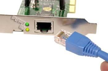
10 Network Interface Card (NIC) 10

11 Network Interface Card (NIC) Network Interface Card (NIC) Layer 2, Data Link Layer, device Connects the device (computer) to the LAN Responsible for the local Layer 2 address Common Layer 2 NICs: Ethernet Token Ring Common Bandwidth 10 Mbps, 10/100 Mbps, 10/100/1000 Mbps 11
 12")
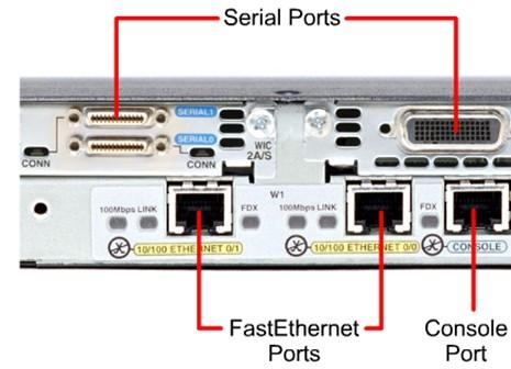
12 Tracing the Physical Connection NIC (Network Interface Card) 12
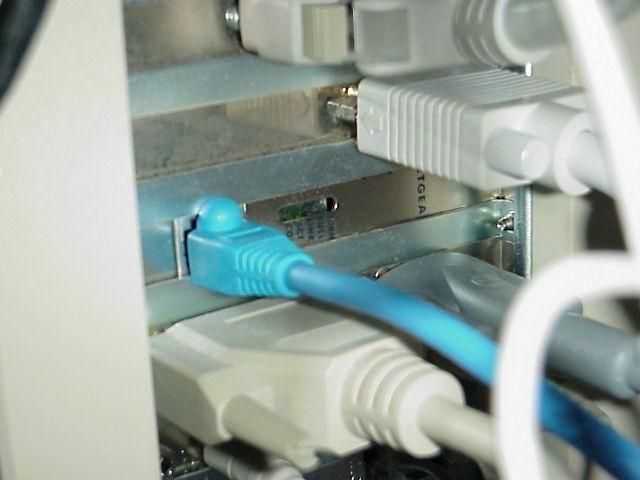
13 Connecting the NIC to a Hub or Switch 13


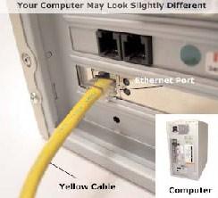
14 From PC to Ethernet Port 14


15 From Ethernet Port to Patch Panel Back View Front View 15
")
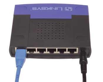
16 From Patch Panel to Switch (or ) 16

17 From PC to Switch 17

18 All of that is the same as these! 18
19 The MAC Address Part of the Ethernet protocol includes the MAC (Media Access Control) coming Every Ethernet NIC card has a unique MAC address. MAC addresses provide a way for computers to identify themselves. They give hosts a permanent, unique name. 19
20 The MAC Address MAC addresses are: 48 bits in length Expressed as 12 hexadecimal digits. The first 6 hexadecimal digits, which are administered by the IEEE, identify the manufacturer or vendor and thus comprise the Organizational Unique Identifier (OUI). The remaining 6 hexadecimal digits comprise the interface serial number, or another value administered by the specific vendor. MAC addresses are sometimes referred to as burned-in addresses (BIAs) because they are burned into read-only memory (ROM) and are copied into random-access memory (RAM) when the NIC initializes 20

21 The MAC Address MAC Address MAC Address The Ethernet protocol uses MAC addresses to identify the source of the Ethernet frame and the destination of the Ethernet frame. Whenever is computer sends an Ethernet frame, it includes the MAC address on its NIC as the Source MAC Address. 21
22 Decimal, Binary, Hex Dec Bin Hex 0 = 0000 = 0 1 = 0001 = 1 2 = 0010 = 2 3 = 0011 = 3 4 = 0100 = 4 5 = 0101 = 5 6 = 0110 = 6 7 = 0111 = 7 Dec Bin Hex 8 = 1000 = 8 9 = 1001 = 9 10 = 1010 = A 11 = 1011 = B 12 = 1100 = C 13 = 1101 = D 14 = 1110 = E 15 = 1111 = F 22
23 MAC Address Format Dec Bin Hex 0 = 0000 = 0 1 = 0001 = 1 2 = 0010 = 2 3 = 0011 = 3 4 = 0100 = 4 5 = 0101 = 5 6 = 0110 = 6 7 = 0111 = 7 Dec Bin Hex 8 = 1000 = 8 9 = 1001 = 9 10 = 1010 = A 11 = 1011 = B 12 = 1100 = C 13 = 1101 = D 14 = 1110 = E 15 = 1111 = F OUI unique An Intel MAC address: E0-6B


24 What is the Address on my NIC? 24
25 MAC Addresses Are Flat MAC addresses provide a way for computers to identify themselves. They give hosts a permanent, unique name. The number of possible MAC addresses is 16^12 (or over 2 trillion!). 25
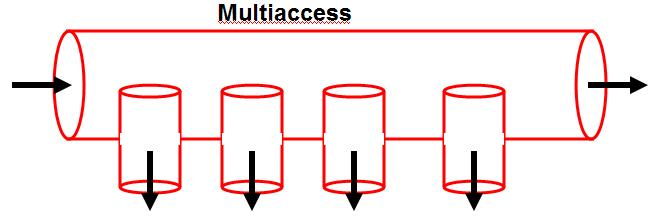
26 Serial vs Multiaccess Network Serial Multiaccess 26
27 27
28 Ethernet: Multiaccess Network 28

29 Bus Topology A bus topology uses a single backbone segment (length of cable) that all the hosts connect to directly. Original Ethernet used a bus topology. By the way, Ethernet s work the same as a bus. 29
30 Sending and receiving Ethernet frames on a bus nnnn Abbreviated MAC Addresses When an Ethernet frame is sent out on the bus all devices on the bus receive it. What do they do with it? 30
31 Sending and receiving Ethernet frames on a bus Nope Hey, that s me! 3333 Nope nnnn Abbreviated MAC Addresses When information (frame) is transmitted, every PC/NIC on the shared media copies part of the transmitted frame to see if the destination address matches the address of the NIC. If there is a match, the rest of the frame is copied If there is NOT a match the rest of the frame is ignored. Unless you are running a protocol analyzer program such as Ethereal. 31
32 Sending and receiving Ethernet frames on a bus nnnn Abbreviated MAC Addresses So, what happens when multiple computers try to transmit at the same time? 32

33 Sending and receiving Ethernet frames on a bus nnnn Abbreviated MAC Addresses X Collision! 33
34 CSMA/CD (Carrier Sense Multiple Access with Collision Detection) CSMA/CD Common contention method used with Ethernet and IEEE Let everyone have access whenever they want and we will work it out somehow. 34
35 CSMA/CD and Collisions CSMA/CD (Carrier Sense Multiple Access with Collision Detection) Listens to the network s shared media to see if any other users on on the line by trying to sense a neutral electrical signal or carrier. If no transmission is sensed, then multiple access allows anyone onto the media without any further permission required. If two PCs detect a neutral signal and access the shared media at the exact same time, a collision occurs and is detected. The PCs sense the collision by being unable to deliver the entire frame onto the network. When a collision occurs, a jamming signal is sent out by the first PC to detect the collision. Using either a priority or random backoff scheme, the PCs wait certain amount of time before retransmitting. If collisions continue to occur, the PCs random interval is doubled, lessening the chances of a collision. 35

36 Sending and receiving Ethernet frames via a Hub or Only one device on the can communicate at a time, otherwise collisions occur. 10 Mbps ports are the most common. 100/1000 Mbps also available. The acts the same as a bus. 36
37 Sending and receiving Ethernet frames via a ? 2222 So, what does a do when it receives information? A is nothing more than a multiport repeater
38 Repeaters Signals can only travel so far through media before they weaken, and become garbled. This weakening of signals is called attenuation. Attenuation increases when: Media distances are lengthened Nodes are added to the media Repeaters: take in weakened signals clean them up regenerate them send them on their way along the network 38
39 Repeater: Layer 1 Device Signal come in signal go out. (after I amplify it) Repeaters are Layer 1 devices. They do NOT look at: Layer 2, Data Link (MAC, Ethernet) addresses Layer 3, IP Addresses. 39

40 Hub Hub is nothing but a multiport repeater. Hubs are Layer 1 devices. Data that comes in one port is sent out all other ports, except for the port it came in on. 40

41 Hubs Hubs allow computers and other network devices to communicate with each other, and use a star topology. Like a repeater, a regenerates the signal. Hubs have the same disadvantage as a repeater, anything it receives on one port, it FLOODS out all other ports. Wherever possible, s should be replace by switches. 41
42 Sending and receiving Ethernet frames via a Nope 5555 Nope 3333 For me! 4444 Nope The will flood it out all ports except for the incoming port. Hub is a layer 1 device. A does NOT look at layer 2 addresses, so it is fast in transmitting data. Disadvantage with s: A or series of s is a single collision domain (coming) A collision will occur if any two or more devices transmit at the same time within the collision domain. 42
43 Sending and receiving Ethernet frames via a For me! 5555 Nope 3333 Nope 4444 Nope Another disadvantage with s is that is take up unnecessary bandwidth on other links. Wasted bandwidth 43
44 Sending and receiving Ethernet frames via a ? What happens when two host on the same, or when multiple s are connected, transmit at the same time? 44
45 Sending and receiving Ethernet frames via a Collision X Collision occurs. Although, s have little latency, CSMA/CD requires resending of frames and adds latency. 45

46 Half-duplex (Introduction) Half-duplex Hubs operate only in Half-duplex. Half-duplex means that only one end can send at a time. With half-duplex NICs, a host can only transmit or receive, not both at the same time, or a collision will occur. When multiple devices are connected to a or series of s, only one device can transmit. Uses CSMA/CD. If the a carrier is detected, then the NIC will not transmit. Ethernet s and repeaters can only operate in half-duplex mode. 46
47 Half-Duplex mode All of these Ethernet NICs and ports on the s are operating in Half-Duplex mode. When multiple devices are connected to a or series of s, only one device can transmit. 47
48 Collision Domain: Shared Access Collision domain (Wikipedia): A group of Ethernet or Fast Ethernet devices in a CSMA/ CD LAN that are connected by repeaters/s and compete for access on the network. Only one device in the collision domain may transmit at any one time, and the other devices in the domain listen to the network in order to avoid data collisions. A collision domain is sometimes referred to as an Ethernet segment. If you connect several computers to a single medium that is only connected by repeaters and s (Layer 1 devices), you have a shared-access situation, and you have a single collision domain. 48
49 Full-duplex Full-duplex is allows simultaneous communication between a pair of stations or devices. Full-duplex allows devices to send and receive at the same time. Both ends of the link must be in full-duplex mode. Most switches operate at either full-duplex but can operate in half-duplex. If a is connected to a switch, the switch port must be in half-duplex. The collision domain will end at the switch port. 49
50 Where are the collision domains? What would be the duplex settings? router 50
51 Where are the collision domains? Single Collision Domain router 51
52 What would be the duplex settings? Half-duplex router Half-duplex 52
53 Where are the collision domains? What would be the duplex settings? router switch switch 53
54 Where are the collision domains? What would be the duplex settings? router switch Collision Domains switch Collision Domains 54
55 What would be the duplex settings? Half-duplex Full-duplex router switch switch Half-duplex 55
56 Where are the collision domains? What would be the duplex settings? router switch switch switch switch switch switch 56
57 Where are the collision domains? router switch switch switch switch switch switch Collision Domains 57
58 What would be the duplex settings? Half-duplex Full-duplex router switch switch switch switch switch switch switch Full-duplex 58
59 Chapter 9 Ethernet Part 2
60 Generic Data Link Frame Format Preamble and Start Field used for synchronization between the sending and receiving devices. Beginning signaling sequence of bytes. the first few bytes tell the receivers to get ready to receive a new frame. 60
61 Generic Data Link Frame Format Address Field We saw how IEEE uses Destination and Source Addresses. Ethernet: Unicast address MAC address of a single device Broadcast address All devices (All 1 bits, All F s in Hex) Multicast address Specific group of devices 61
62 Unicast, Multicast, Broadcast Destination Addresses Unicast address: A single Ethernet frame to be received by a single station. Unknown Unicast: This is from the perspective of a switch, when the unicast address is not in its MAC Address Table Multicast address: A single Ethernet frame to be received by a group of stations. Broadcast address: Special case of a multicast address, which is all 1 s. This is an Ethernet frame to be received by all stations. 62
63 Generic Data Link Frame Format Length/Type Field Usually information indicating the layer 3 protocols in the data field, I.e. IP Packet. Type field values of particular note for IEEE frames include: 0x0600 XNS (Xerox) 0x0800 IP (Internet protocol) 0x8137 Novell NetWare packet formatted for Ethernet II 0x0806 ARP Message 63

64 Generic Data Link Frame Format Data Field Included along with this data, you must also send a few other bytes. They are called padding bytes, and are sometimes added so that the frames have a minimum length for timing purposes. 64

65 Sending and receiving Ethernet frames via a switch Layer 2 device (also includes layer 1) which examines and bases its decisions on the information in layer 2 frames Switch ports typically operate in full-duplex. Multiple devices on the switch can communicate at a time, otherwise collisions occur. 10/100 Mbps ports are the most common Mbps also are also common, usually connecting to another switch or router. 65

66 Full-duplex Full-duplex is allows simultaneous communication between a pair of stations or devices. Full-duplex allows devices to send and receive at the same time. Both ends of the link must be in full-duplex mode. If a is connected to a switch, the switch port must be in half-duplex. The collision domain will end at the switch port. 66
67 Learning Switches: Learns Source MAC Address MAC Address Table Port Source MAC Add Port Source MAC Add switch Abbreviated MAC addresses Switches are also known as learning bridges or learning switches. A switch has a source address table (or MAC Address Table) in cache (RAM) where it stores a source MAC address after it learns about them. How does it learn source MAC addresses? Whenever a frame enters a switch, it will first see if the Source Address (1111) is in it s table. If it is, it resets the timer If it is NOT in the table it adds 67 it, with the port number.
68 Destination MAC Address: Filter or Flood MAC Address Table Port Source MAC Add Port Source MAC Add Next, the switch examines the source address table for the Destination MAC address. If it finds a match, it filters the frame by only sending it out that port. If there is not a match if floods it out all ports. In this scenario, the switch will flood the frame out all other ports, because the Destination Address is not in the source address table. switch Abbreviated MAC addresses
69 Learning Switches: Learns, Filter or Flood MAC Address Table Port Source MAC Add Port Source MAC Add Most communications involve some sort of client-server relationship or exchange of information. Now 3333 sends data back to The switch sees if it has the Source Address stored. It does NOT so it adds it. (This will help next time 1111 sends to 3333.) Next, it checks the Destination Address and in our case it can filter the frame, by sending it only out port 1. switch Abbreviated MAC addresses
70 Destination Address in table, Filter MAC Address Table Port Source MAC Add Port Source MAC Add switch Now, because both MAC addresses are in the switch s table, any information exchanged between 1111 and 3333 can be sent (filtered) out the appropriate port Abbreviated MAC addresses What happens when two devices send to same destination? What if this was a? Where is (are) the collision domain(s) in this example? 70
71 No Collisions in Switch, Buffering MAC Address Table Port Source MAC Add Port Source MAC Add switch Unlike a, a collision does NOT occur, which would cause the two PCs to have to retransmit the frames. Collision domains end at the switch Instead the switch buffers the frames and sends them out port #6 one at a time. The sending PCs have no idea that their was another PC wanting to send to the same destination Abbreviated MAC addresses
72 MAC Duplex No collisions MAC Address Table Port Source MAC Add Port Source MAC Add No Collision Domains switch When there is only one device on a switch port, the collision domain is only between the PC and the switch, which is non-existent with full-duplex. With a full-duplex PC and switch port, there will be no collision, since the devices and the medium can send and receive at the same time Abbreviated MAC addresses
73 Other Information MAC Address Table Port Source MAC Add Port Source MAC Add switch Abbreviated MAC addresses How long are addresses kept in the Source Address Table? 5 minutes is common on most vendor switches. How do computers know the Destination MAC address? ARP Caches and ARP Requests How many addresses can be kept in the table? Depends on the size of the cache, but 1,024 addresses is common. What about Layer 2 broadcasts? Layer 2 broadcasts (DA = all 1 s) is flooded out all ports. 73
74 What happens here? MAC Address Table Port Source MAC Add Port Source MAC Add Notice the Source Address Table has multiple entries for port #
75 What happens here? MAC Address Table Port Source MAC Add Filter Port Source MAC Add Reset timer The switch resets the 5 minute timer on the source port entry. The switch filters the frame out port #1. But the is only a layer 1 device, so a floods it out all ports. Where is the collision domain?
76 What happens here? Source Address Table Port Source MAC Add. Port Source MAC Add Collision Domain

77 Unshielded Twisted Pair (UTP) Straight-through Cross-over Rollover public/701/14.html 77
78 UTP Straight-through Cable Hub or Switch Host or Router The cable that connects from the switch port to the computer NIC port is called a straight-through cable. Connects unlike devices. 78
79 UTP Straight-through Cable Hub or Switch Host or Router 79

80 UTP Cross-over Cable Hub or Switch Hub or Switch The cable that connects from one switch port to another switch port is called a crossover cable. Connects like devices. 80
81 Cabling Show the straight-through and crossover cables router switch switch 81
82 Cabling Show the straight-through and crossover cables Straight-through cable Cross-over cable router switch switch 82

83 Configuring Speed and Duplex Negotiation between NIC and switch port. Duplex: Full-duplex or Half-duplex Speed: 10/100/1000 Mbps Autonegotiation Both sides of a link should have auto-negotiation on, or both sides should have it off. 83
84 Evolution of Ethernet and Half-Duplex (CSMA/CD)
85 Ethernet is Best Effort Delivery Ethernet is best-effort delivery, no guarantee. Like a trucking service, it doesn t really know or care about the what it is carrying. 85
86 IEEE Identifiers Early Standards Older Fiber Standards 100 Mbps Media 1000 Mbps Media 10BASE5 10BASE-F 100BASE-T 1000BASE-X 10BASE2 10BASE-FB 100BASE-X 1000BASE-SX FOIRL 10BASE-FP 100BASE-TX 1000BASE-LX 10BROAD36 10BASE-FL 100BASE-FX 1000BASE-CX 1BASE5 100BASE-T4 1000BASE-T 10BASE-T 100BASE-T2 Many of these standards were short lived or never implemented 3 part identifier Speed in Mbps Type of signaling used (Baseband or Broadband) Distance or Medium Early days: Cable Distance in meters, rounded to the nearest 100 meters Later days: Physical medium used 86
 100 refers to 100 Mbps TX Two pairs of Category 5 Twisted-pair cable")
87 IEEE Identifiers 10BASE5 (Thick Ethernet) 10 refers to 10 Mbps Baseband: Dedicated to carrying one type of service Broadband: (Cable television) Designed to deliver multiple channels 5 refers to 500 meter maximum distance 100BASE-TX (Most widely used variety of Fast Ethernet) 100 refers to 100 Mbps TX Two pairs of Category 5 Twisted-pair cable 87
88 IFG Interframe Gap Ethernet Frame IFG Ethernet Frame IFG Ethernet Frame IFG Ethernet Frame IFG Ethernet devices must allow a minimum idle period between transmission of frames known as the interframe gap (IFG) or interpacket gap (IPG). Note: Both half and full-duplex It provides a brief recovery time between frames to allow devices to prepare for reception of the next frame. The minimum interframe gap is: 10 Mbps Ethernet: 96 bit times, which is 9.6 microseconds (millionths of a second) 100 Mbps, Fast Ethernet: 960 nanoseconds (billionths of a second) 1000 Mbps, Gigabit Ethernet: 96 nanoseconds 88
89 Collisions, Slot time and Minimum Frame Size Notes Original Ethernet (802.3) designed as Half-duplex CSMA/CD is based on half-duplex and is NOT part of full-duplex Collisions are part of CSMA/CD and half-duplex Ethernet Collisions are a normal part of operation and are NOT errors Collisions are NOT part of full-duplex Ethernet 89

90 Collision Domain Collision Domain: Refers to a single half-duplex Ethernet system whose elements (cables, repeaters, s, station interfaces and other network hardware) are all part of the same signal timing domain. If two or more devices transmit at the same time a collision will occur. If a collision is detected, the station will continue to transmit 32 bits called the collision enforcement jam signal. 90
91 Collision Domain Switches do not forward collision signals 91

92 Slot Time The slot time ensures that if a collision is going to occur, it will be detected within the first 512 bits (4096 for Gigabit Ethernet) of the frame transmission. The 512-bit slot time establishes the minimum size of an Ethernet frame as 64 bytes. Any frame less than 64 bytes in length is considered a "collision fragment" or "runt frame" and is automatically discarded by receiving stations. The slot time establishes a limit on the maximum size of a network's segments. If 92 the network grows too big, late collisions can occur.
93 Chapter 9 ARP
94 TCP/IP and ARP The TCP/IP Suite of Protocols Application Transport Internet/Network Network Interface (Link Layer) File Transfer: FTP, TFTP, NFS, HTTP SMTP Remote Login: Telnet, rlogin Network Management: SNMP, BootP Name Management: DNS, DHCP TCP, UDP IP, ICMP, IGMP, ARP, RARP Not Specified: Ethernet, 802.3, Token Ring, 802.5, FDDI, ATM, ARP is a layer 3 protocol, one of many protocols within the TCP/IP suite of protocols. 94
95 Why do devices have a MAC Address and an IP Address? 00-0D-178A-F1-32 IP addresses: Original source address of the sending device Final destination address of the intended recipient. do not change Data Link addresses, such as Ethernet MAC addresses are used to get the IP packet from one hop to the next, within the same network. Next hop is either: A router on this network The final destination of the packet (Destination IP address) 95
96 Layer 2 Data Link Frame Dest. Dest.MAC Add MAC 0B-31 FF-FF 0B Source MAC Add 0A C-22 Layer 3 IP Packet Type 800 Dest. IP Source IP IP fields Data Trailer The sending host builds message with multiple encapsulations. Data Link Header IP Header TCP Header HTTP Header Data Data Link Trailer The receiving host receives the message with multiple decapsulations. Data Link Header IP Header TCP Header HTTP Header Data Data Link Trailer 96
97 Destination MAC Address What does the Ethernet Destination MAC Address do? Allows the transmission of the data (e.g. IP packet) to a device on the same LAN (also has an Ethernet NIC). Hosts, printers, etc. with that belong to the same IP network. Default gateway, Router, which also has an IP address on the same network. 97
98 Destination MAC Address 00-0C AA Same network What would the Destination MAC address be for IP packets sent within the same LAN, network? The Destination MAC address would be that of the device that we are sending the IP packet to. The device s Destination MAC address would be associated with the Destination IP address. 98
99 Destination MAC Address 00-0D-178A-F1-32 Different network What would the Destination MAC address for IP packets sent outside the LAN, on a different network? The destination MAC address will be the MAC address associated with the IP Address of the Default Gateway. The host must know the IP address of the Default Gateway to communicate with devices outside its own network. 99
100 Destination MAC Address? Same network? Same Network: Destination IP Address s MAC Address Different Network: The Default Gateway s MAC Address The Destination MAC Address will always be one of two addresses. Same network: The MAC address associated with the device s Destination IP Address. Different network: The MAC address associated with the IP Address of the Default Gateway. 100
101 ARP: Address Resolution Protocol The ARP Table or ARP Cache The TCP/IP Suite of Protocols Application Transport Internet/Network Network Interface (Link Layer) File Transfer: FTP, TFTP, NFS, HTTP SMTP Remote Login: Telnet, rlogin Network Management: SNMP, BootP Name Management: DNS, DHCP TCP, UDP IP, ICMP, IGMP, ARP, RARP Not Specified: Ethernet, 802.3, Token Ring, 802.5, FDDI, ATM, IP Address to MAC Address Mappings 101
102 Same network 00-0C CC 00-0C AA Destination MAC Address??? ARP Table IP Address MAC Address C A C AA C C-A C1 It will look for it in it s ARP Table or ARP Cache. The ARP Table maintains IP Address to MAC Address mappings. Every device that participates in Ethernet and IP will have such a table, including hosts and routers. Host Stevens MAC 00-0C CC Host Cerf MAC 00-0C AA Source Destination /24 Router A Ethernet MAC 03-0D-17-8A-F
103 Same network 00-0C CC Destination MAC Address??? No Match IP Address ARP Table MAC Address 00-0C A1 00-0C C-A C1 What if the Destination IP Address is not in the ARP Table? How does it get in there? The host must issue an ARP Request. Host Stevens MAC 00-0C CC Host Cerf MAC 00-0C AA Source Destination /24 Router A Ethernet MAC 03-0D-17-8A-F
104 ARP: A quick look Destination MAC Address??? IP Address ARP Table MAC Address 00-0C A1 00-0C C-A C1 00-0C AA 00-0C CC Hey that s me! C AA Host Stevens L2 Broadcast to all ARP Request: Who has IP Address ? Please send me your devices on network MAC 00-0C CC MAC Address. Source I will add that to my ARP Table. I will now use the MAC Address to forward the frame. IP Packet no putlonger on hold on hold Host Cerf ARP Reply: Here is my MAC Address MAC 00-0C AA L2 Unicast only to sender of ARP Request Destination IP Packet now sent to Destination /24 Router A Ethernet MAC 03-0D-17-8A-F
Objectives. Hexadecimal Numbering and Addressing. Ethernet / IEEE LAN Technology. Ethernet
 2007 Cisco Systems, Inc. All rights reserved. Cisco Public Objectives Ethernet Network Fundamentals Chapter 9 ITE PC v4.0 Chapter 1 1 Introduce Hexadecimal number system Describe the features of various
CCNA Exploration Network Fundamentals. Chapter 09 Ethernet
 CCNA Exploration Network Fundamentals Chapter 09 Ethernet Updated: 07/07/2008 1 9.0.1 Introduction 2 9.0.1 Introduction Internet Engineering Task Force (IETF) maintains the functional protocols and services
CS 43: Computer Networks Switches and LANs. Kevin Webb Swarthmore College December 5, 2017
 CS 43: Computer Networks Switches and LANs Kevin Webb Swarthmore College December 5, 2017 Ethernet Metcalfe s Ethernet sketch Dominant wired LAN technology: cheap $20 for NIC first widely used LAN technology
Raj Jain. The Ohio State University Columbus, OH
 Columbus, OH 43210 Jain@CIS.Ohio-State.Edu http://www.cis.ohio-state.edu/~jain/ 3-1 Overview ISO/OSI Reference Model TCP/IP Reference Model Differences between ISO and TCP Ethernet/IEEE 802.3 LANs Interconnecting
Part3. Local Area Networks (LAN)
") Part3 Local Area Networks (LAN) LAN Characteristics Small geographical area Relatively high data rate Single management Topologies Bus, star, ring Specifications at physical and data link layer mostly
Part3 Local Area Networks (LAN) LAN Characteristics Small geographical area Relatively high data rate Single management Topologies Bus, star, ring Specifications at physical and data link layer mostly
Chapter 9. Ethernet. Part II
 Chapter 9 Ethernet Part II CCNA1-1 Chapter 9-2 Note for Instructors These presentations are the result of a collaboration among the instructors at St. Clair College in Windsor, Ontario. Thanks must go
Overview of Ethernet Networking
 Overview of Ethernet Networking Renesas Electronics America Inc. 1/31/2011 Rev. 0.02 00000-A Agenda This course contains an overview of Ethernet technology and its advantages and limits. Contained in this
Lecture (04) Network Layer (Physical/Data link) 2
 Network Layer (Physical/Data link) 2") Lecture (04) Network Layer (Physical/Data link) 2 By: Dr. Ahmed ElShafee ١ Dr. Ahmed elshafee, ACU : Spring 2018, CSE401 Computer Networks Agenda Ethernet standards 10 base 5 10 base 2 10 base T Fast Ethernet
Lecture (04) Network Layer (Physical/Data link) 2 By: Dr. Ahmed ElShafee ١ Dr. Ahmed elshafee, ACU : Spring 2018, CSE401 Computer Networks Agenda Ethernet standards 10 base 5 10 base 2 10 base T Fast Ethernet
LAN PROTOCOLS. Beulah A AP/CSE
 LAN PROTOCOLS Beulah A AP/CSE IEEE STANDARDS In 1985, the Computer Society of the IEEE started a project, called Project 802, to set standards to enable intercommunication among equipment from a variety
NT1210 Introduction to Networking. Unit 5:
 NT1210 Introduction to Networking Unit 5: Chapter 5, Ethernet LANs 1 Objectives Identify the major needs and stakeholders for computer networks and network applications. Identify the classifications of
Networking Technologies and Applications
 Networking Technologies and Applications Rolland Vida BME TMIT September 23, 2016 Aloha Advantages: Different size packets No need for synchronization Simple operation If low upstream traffic, the solution
Local Area Networks. Aloha Slotted Aloha CSMA (non-persistent, 1-persistent, p-persistent) CSMA/CD Ethernet Token Ring
 CSMA/CD Ethernet Token Ring") Local Area Networks Aloha Slotted Aloha CSMA (non-persistent, 1-persistent, p-persistent) CSMA/CD Ethernet Token Ring Networks: Local Area Networks 1 Network Layer Network Layer LLC 802.2 Logical Link
Local Area Networks Aloha Slotted Aloha CSMA (non-persistent, 1-persistent, p-persistent) CSMA/CD Ethernet Token Ring Networks: Local Area Networks 1 Network Layer Network Layer LLC 802.2 Logical Link
Interface The exit interface a packet will take when destined for a specific network.
 The Network Layer The Network layer (also called layer 3) manages device addressing, tracks the location of devices on the network, and determines the best way to move data, which means that the Network
Computer Networks. Lecture 8 Local Area Network, IEEE 802.x
 Computer Networks Lecture 8 Local Area Network, IEEE 802.x Local area network A local area network (LAN) is a computer network that interconnects computers within a limited area such as a home, school,
Lecture 4b. Local Area Networks and Bridges
 Lecture 4b Local Area Networks and Bridges Ethernet Invented by Boggs and Metcalf in the 1970 s at Xerox Local area networks were needed to connect computers, share files, etc. Thick or Thin Ethernet Cable
Computer Networks Medium Access Control. Mostafa Salehi Fall 2008
 Computer Networks Medium Access Control Mostafa Salehi Fall 2008 2008 1 Outline Issues ALOHA Network Ethernet Token Ring Wireless 2 Main Issues Local Area Network (LAN) : Three or more machines are physically
ROYAL INSTITUTE OF INFORMATION & MANAGEMENT
 ROYAL INSTITUTE OF INFORMATION & MANAGEMENT BASICS NETWORKING CHAPTER 1 Networking Basics to Networking Advantages of Networking Types of Network 1 Local Area Network (LAN) LAN features Basic LAN components
Lecture (04 & 05) Data link layer fundamental
 Data link layer fundamental") Lecture (04 & 05) Data link layer fundamental Dr. Ahmed M. ElShafee ١ Agenda Foundation Topics Typical LAN Features for OSI Layer 1 Typical LAN Features for OSI Layer 2 Standards Overview 10BASE2 and 10BASE5
Lecture (04 & 05) Data link layer fundamental Dr. Ahmed M. ElShafee ١ Agenda Foundation Topics Typical LAN Features for OSI Layer 1 Typical LAN Features for OSI Layer 2 Standards Overview 10BASE2 and 10BASE5
Lecture (04) Network Access layer fundamentals I
 Network Access layer fundamentals I") Lecture (04) Network Access layer fundamentals I By: Dr. Ahmed ElShafee Typical LAN Features for Physical layer Typical LAN Features for Data link layer Standards Overview 10BASE2 and 10BASE5 10BASE T
Lecture (04) Network Access layer fundamentals I By: Dr. Ahmed ElShafee Typical LAN Features for Physical layer Typical LAN Features for Data link layer Standards Overview 10BASE2 and 10BASE5 10BASE T
Lecture (04) Network Access layer fundamentals I
 Network Access layer fundamentals I") Lecture (04) Network Access layer fundamentals I By: Dr. Ahmed ElShafee ١ Dr. Ahmed ElShafee, ACU : Fall 2014, Computer Networks II Typical LAN Features for Physical layer Typical LAN Features for Data
Lecture (04) Network Access layer fundamentals I By: Dr. Ahmed ElShafee ١ Dr. Ahmed ElShafee, ACU : Fall 2014, Computer Networks II Typical LAN Features for Physical layer Typical LAN Features for Data
Zarządzanie sieciami telekomunikacyjnymi
 Ethernet The term Ethernet refers to the family of local-area network (LAN) products covered by the IEEE 802.3 standard that defines what is commonly known as the CSMA/CD protocol. Four data rates are
Lecture (04) Data link layer
 Data link layer") Lecture (04) Data link layer By: Dr. Ahmed ElShafee Standards Overview CSMA/CD Ethernet standards 10 base 5 10 base 2 10 base T Fast Ethernet Gigabit Ethernet ١ ٢ Standards Overview Like most protocols,
Lecture (04) Data link layer By: Dr. Ahmed ElShafee Standards Overview CSMA/CD Ethernet standards 10 base 5 10 base 2 10 base T Fast Ethernet Gigabit Ethernet ١ ٢ Standards Overview Like most protocols,
Ethernet Basics. based on Chapter 4 of CompTIA Network+ Exam Guide, 4 th ed., Mike Meyers
 Ethernet Basics based on Chapter 4 of CompTIA Network+ Exam Guide, 4 th ed., Mike Meyers Ethernet Basics History Ethernet Frames CSMA/CD Obsolete versions 10Mbps versions Segments Spanning Tree Protocol
Data Link Layer. Our goals: understand principles behind data link layer services: instantiation and implementation of various link layer technologies
 Data Link Layer Our goals: understand principles behind data link layer services: link layer addressing instantiation and implementation of various link layer technologies 1 Outline Introduction and services
Data Link Layer, Part 3 Medium Access Control. Preface
 Data Link Layer, Part 3 Medium Access Control These slides are created by Dr. Yih Huang of George Mason University. Students registered in Dr. Huang's courses at GMU can make a single machine-readable
Principles behind data link layer services
 Data link layer Goals: Principles behind data link layer services Error detection, correction Sharing a broadcast channel: Multiple access Link layer addressing Reliable data transfer, flow control: Done!
IEEE standards for local area networks
 IEEE standards for local area networks Telecommunication Networks Group firstname.lastname@polito.it http://www.telematica.polito.it/ COMPUTER NETWORKS Standard for LANs 1 Copyright Quest opera è protetta
Ethernet Hub. Campus Network Design. Hubs. Sending and receiving Ethernet frames via a hub
 Campus Network Design Thana Hongsuwan Ethernet Hub 2003, Cisco Systems, Inc. All rights reserved. 1-1 2003, Cisco Systems, Inc. All rights reserved. BCMSN v2.0 1-2 Sending and receiving Ethernet frames
EE-379 Embedded Systems and Applications Introduction to Ethernet
 EE-379 Embedded Systems and Applications Introduction to Ethernet Cristinel Ababei Department of Electrical Engineering, University at Buffalo Spring 2013 Note: This course is offered as EE 459/500 in
IEEE 802 LANs SECTION C
 IEEE 802 LANs SECTION C Outline of the Lecture Basic characteristics of LAN Topology Transmission Media MAC IEEE 802 LANs 802.3 - CSMA/CD based (Ethernet) 802.4 Token bus-based 802.5 Token ring-based Comparison
Link Layer and Ethernet
 Link Layer and Ethernet 14-740: Fundamentals of Computer Networks Bill Nace Material from Computer Networking: A Top Down Approach, 6 th edition. J.F. Kurose and K.W. Ross traceroute Data Link Layer Multiple
Fundamentals of Networking. OSI & TCP/IP Model. Kuldeep Sonar 1
 Fundamentals of Networking OSI & TCP/IP Model Kuldeep Sonar 1 Kuldeep Sonar 2 OSI Model Kuldeep Sonar 3 Application Layer Layer 7 provides an interface between a host s communication software and any necessary
Link Layer and Ethernet
 Link Layer and Ethernet 14-740: Fundamentals of Computer Networks Bill Nace Material from Computer Networking: A Top Down Approach, 6 th edition. J.F. Kurose and K.W. Ross traceroute Data Link Layer Multiple
Chapter 5 Reading Organizer After completion of this chapter, you should be able to:
 Chapter 5 Reading Organizer After completion of this chapter, you should be able to: Describe the operation of the Ethernet sublayers. Identify the major fields of the Ethernet frame. Describe the purpose
CSCD 330 Network Programming Spring 2017
 CSCD 330 Network Programming Spring 2017 Lecture 18 Link Layer Protocols Continued Who is this? Reading: Chapter 5 Some slides provided courtesy of J.F Kurose and K.W. Ross, All Rights Reserved, copyright
Imi :... Data:... Nazwisko:... Stron:...
 Imi :.................................................... Data:....................... Nazwisko:............................................... Stron:...................... 1. Which of the following protocols
Layering in Networked computing. OSI Model TCP/IP Model Protocols at each layer
 Layering in Networked computing OSI Model TCP/IP Model Protocols at each layer Learning outcomes Understand the need of layering in Networked computing Understand the OSI model and the tcp/ip model Understand
EITF25 Internet Techniques and Applications L4: Network Access. Stefan Höst
 EITF25 Internet Techniques and Applications L4: Network Access Stefan Höst Repetition The link layer protocol should make sure that the data is correctly transmitted over the physical link using error
Medium Access Protocols
 Medium Access Protocols Summary of MAC protocols What do you do with a shared media? Channel Partitioning, by time, frequency or code Time Division,Code Division, Frequency Division Random partitioning
Internet Architecture and Protocol
 Internet Architecture and Protocol Set# 03 Local Area Networks Delivered By: Engr Tahir Niazi Layer Reference to Protocol Application Presentation Session Application FTP, Telnet, SMTP, HTTP, SNMP.. Transport
CSCD 330 Network Programming Winter 2016
 CSCD 330 Network Programming Winter 2016 Lecture 18 Link Layer Protocols Continued Who is this? Reading: Chapter 5 Some slides provided courtesy of J.F Kurose and K.W. Ross, All Rights Reserved, copyright
Data Link Layer, Part 5. Medium Access Control
 CS 455 Medium Access Control, Page 1 Data Link Layer, Part 5 Medium Access Control These slides are created by Dr. Yih Huang of George Mason University. Students registered in Dr. Huang s courses at GMU
A LAN is a high-speed data network that covers a relatively small geographic area. It typically connects workstations, personal computers, printers,
 CBCN4103 A LAN is a high-speed data network that covers a relatively small geographic area. It typically connects workstations, personal computers, printers, servers, and other devices. LANs offer computer
Data Link Layer -2- Network Access
 EITF25 Internet: Technology and Applications Data Link Layer -2- Network Access 2015, Lecture 03 Kaan Bür Previously on EITF25 Logical Link Control Sublayer Flow control Send data Wait for ACK Error control
Summary of MAC protocols
 Summary of MAC protocols What do you do with a shared media? Channel Partitioning, by time, frequency or code Time Division, Code Division, Frequency Division Random partitioning (dynamic) ALOHA, S-ALOHA,
Cisco Cisco Certified Network Associate (CCNA)
") Cisco 200-125 Cisco Certified Network Associate (CCNA) http://killexams.com/pass4sure/exam-detail/200-125 Question: 769 Refer to exhibit: Which destination addresses will be used by Host A to send data
Cisco 200-125 Cisco Certified Network Associate (CCNA) http://killexams.com/pass4sure/exam-detail/200-125 Question: 769 Refer to exhibit: Which destination addresses will be used by Host A to send data
The Internet software layers
 1 2 The Internet software layers SMTP, Telnet, FTP, POP3, IMAP TCP, UDP IP: RIP, BGP, OSPF Ethernet, Wireless LAN, Token Ring Twisted pair, coaxial, microwave, optical fiber 3 4 Ethernet 1973 Xerox s researcher
Lecture 5 The Data Link Layer. Antonio Cianfrani DIET Department Networking Group netlab.uniroma1.it
 Lecture 5 The Data Link Layer Antonio Cianfrani DIET Department Networking Group netlab.uniroma1.it Link Layer: setting the context two physically connected devices: host-router, router-router, host-host,
Internetworking is connecting two or more computer networks with some sort of routing device to exchange traffic back and forth, and guide traffic on
 CBCN4103 Internetworking is connecting two or more computer networks with some sort of routing device to exchange traffic back and forth, and guide traffic on the correct path across the complete network
Ethernet. Networks: Ethernet 1
 Ethernet Networks: Ethernet 1 Ethernet [DEC, Intel, Xerox] 1-persistent, CSMA-CD with Binary Exponential Backoff Manchester encoding Networks: Ethernet 2 Ethernet [operational in 1974] Initially 3 Mbps
Principles behind data link layer services:
 Data Link Layer Goals: Principles behind data link layer services: Error detection, correction Sharing a broadcast channel: multiple access Link layer addressing Reliable data transfer, flow control: Done!
Copyleft 2005, Binnur Kurt. Objectives
 1 ing Fundamentals Copyleft 2005, Binnur Kurt Objectives Define basic networking terms Describe some commonly used network applications Describe the main purposes and functions of computer networking Describe
Chapter 2. Switch Concepts and Configuration. Part I
 Chapter 2 Switch Concepts and Configuration Part I CCNA3-1 Chapter 2-1 Note for Instructors These presentations are the result of a collaboration among the instructors at St. Clair College in Windsor,
10- and 100-Mbps Ethernet
 Ethernet Basics 10-Mbps Ethernet Three 10-Mbps Ethernet standards: 10BASE5 10BASE2 10BASE-T 10BASE2 and 10BASE5 were around more than 20 years and have been replaced by newer alternatives 10BASE-T s use
Data and Computer Communications
 Data and Computer Communications Chapter 16 High Speed LANs Eighth Edition by William Stallings Why High Speed LANs? speed and power of PCs has risen graphics-intensive applications and GUIs see LANs as
Principles behind data link layer services:
 Data link layer Goals: Principles behind data link layer services: Error detection, correction Sharing a broadcast channel: Multiple access Link layer addressing Reliable data transfer, flow control Example
Principles behind data link layer services:
 Data link layer Goals: Principles behind data link layer services: Error detection, correction Sharing a broadcast channel: Multiple access Link layer addressing Reliable data transfer, flow control Example
Solved MCQ of Computer networking. Set-1
 Solved MCQ of Computer networking Set-1 1. The computer network is A) Network computer with cable B) Network computer without cable C) Both of the above D) None of the above 2. FDDI used which type of
Data Link Layer -2- Network Access
 EITF25 Internet: Technology and Applications Data Link Layer -2- Network Access 2013, Lecture 03 Kaan Bür, Stefan Höst Previously on EITF25 Logical Link Control Sublayer Flow control Send data Wait for
LAN. CS 4/55231 Internet Engineering. Kent State University Dept. of Computer Science
 1 CS 4/55231 Internet Engineering Kent State University Dept. of Computer Science LECT-4A4 LAN 1 2 LAN Topologies-1 In the last class we saw how two computers can connect to each other. In this class we
Chapter 5: Ethernet. Introduction to Networks - R&S 6.0. Cisco Networking Academy. Mind Wide Open
 Chapter 5: Ethernet Introduction to Networks - R&S 6.0 Cisco Networking Academy Mind Wide Open Chapter 5 - Sections 5.1 Ethernet Protocol Describe the Ethernet MAC address and frame fields 5.2 LAN Switches
Question 7: What are Asynchronous links?
 Question 1:.What is three types of LAN traffic? Unicasts - intended for one host. Broadcasts - intended for everyone. Multicasts - intended for an only a subset or group within an entire network. Question2:
RMIT University. Data Communication and Net-Centric Computing COSC 1111/2061/1110. Lecture 8. Medium Access Control Methods & LAN
 RMIT University Data Communication and Net-Centric Computing COSC 1111/2061/1110 Medium Access Control Methods & LAN Technology Slide 1 Lecture Overview During this lecture, we will Look at several Multiple
Internetwork Basic. Possible causes of LAN traffic congestion are
 Internetworking 1 C H A P T E R 2 Internetworking Basics Internetworking Model The OSI Reference Model Ethernet Networking Wireless Networking Data Encapsulation Topic 3 1 Internetwork Basic 4 Possible
Defining Networks with the OSI Model. Module 2
 Defining Networks with the OSI Model Module 2 Objectives Skills Concepts Objective Domain Description Objective Domain Number Understanding OSI Basics Defining the Communications Subnetwork Defining the
The Link Layer and LANs: Ethernet and Swiches
 The Link Layer and LNs: Ethernet and Swiches EECS3214 2018-03-21 Link layer, LNs: outline 6.1 introduction, services 6.2 error detection, correction 6.3 multiple access protocols 6.4 LNs addressing, RP
Chapter 6: DataLink Layer - Ethernet Olivier Bonaventure (2010)
") Chapter 6: DataLink Layer - Ethernet Olivier Bonaventure (2010) 6.3.2. Ethernet Ethernet was designed in the 1970s at the Palo Alto Research Center [Metcalfe1976]. The first prototype [5] used a coaxial
Chapter 6: DataLink Layer - Ethernet Olivier Bonaventure (2010) 6.3.2. Ethernet Ethernet was designed in the 1970s at the Palo Alto Research Center [Metcalfe1976]. The first prototype [5] used a coaxial
Lecture 6 The Data Link Layer. Antonio Cianfrani DIET Department Networking Group netlab.uniroma1.it
 Lecture 6 The Data Link Layer Antonio Cianfrani DIET Department Networking Group netlab.uniroma1.it Link Layer: setting the context two physically connected devices: host-router, router-router, host-host,
Interconnecting Networks with TCP/IP. 2000, Cisco Systems, Inc. 8-1
 Interconnecting Networks with TCP/IP 2000, Cisco Systems, Inc. 8-1 Objectives Upon completion of this chapter you will be able to perform the following tasks: Identify the IP protocol stack, its protocol
Introduction to LAN Protocols
 CHAPTER 2 Introduction to LAN Protocols This chapter introduces the various media-access methods, transmission methods, topologies, and devices used in a local area network (LAN). Topics addressed focus
Lecture 05 Chapter 16 High Speed LANs
 NET 456 High Speed Networks Lecture 05 Chapter 16 High Speed LANs Dr. Anis Koubaa Reformatted slides from textbook Data and Computer Communications, Ninth Edition by William Stallings, 1 (c) Pearson Education
Introduction to LAN Protocols
 CHAPTER 2 Chapter Goals Learn about different LAN protocols. Understand the different methods used to deal with media contention. Learn about different LAN topologies. This chapter introduces the various
Network Security Fundamentals. Network Security Fundamentals. Roadmap. Security Training Course. Module 2 Network Fundamentals
 Network Security Fundamentals Security Training Course Dr. Charles J. Antonelli The University of Michigan 2013 Network Security Fundamentals Module 2 Network Fundamentals Roadmap Network Fundamentals
SYSTEMS ADMINISTRATION USING CISCO (315)
") Page 1 of 10 Contestant Number: Time: Rank: SYSTEMS ADMINISTRATION USING CISCO (315) REGIONAL 2014 TOTAL POINTS (500) Failure to adhere to any of the following rules will result in disqualification: 1.
Page 1 of 10 Contestant Number: Time: Rank: SYSTEMS ADMINISTRATION USING CISCO (315) REGIONAL 2014 TOTAL POINTS (500) Failure to adhere to any of the following rules will result in disqualification: 1.
Section 3 Understanding Ethernet and Switch Operations
 Section 3 Understanding Ethernet and Switch Operations Ethernet is the technology of choice for today s LANs. It is fast, has low costs, and is easy to maintain. Today s Ethernet standards support speeds
2. LAN Topologies Gilbert Ndjatou Page 1
 2. LAN Topologies Two basic categories of network topologies exist, physical topologies and logical topologies. The physical topology of a network is the cabling layout used to link devices. This refers
CHAPTER 2 SINGLE SEGMENT NETWORKS
 CHAPTER 2 SINGLE SEGMENT NETWORKS Chapter 2 focuses on topics related to the transmission of IP datagrams over a single Ethernet segment. The first section gives an overview of Ethernet. The second sections
CHAPTER 2 - NETWORK DEVICES
 CHAPTER 2 - NETWORK DEVICES TRUE/FALSE 1. Repeaters can reformat, resize, or otherwise manipulate the data packet. F PTS: 1 REF: 30 2. Because active hubs have multiple inbound and outbound connections,
ELEC / COMP 177 Fall Some slides from Kurose and Ross, Computer Networking, 5 th Edition
 ELEC / COMP 177 Fall 2011 Some slides from Kurose and Ross, Computer Networking, 5 th Edition Project #2 Due Thursday, Nov 10 th By midnight Homework #5 Due Thursday, Nov 17 th Later this semester: Homework
BABU MADHAV INSTITUTE OF INFORMATION TECHNOLOGY, UTU 2017
 5 years Integrated M.Sc (IT) Semester 3 Question Bank 060010310 DSE4 Computer Networks Unit 1 Introduction Short Questions 1. State the term data with respect to computer network. 2. What is data communication?
Introductory to Computer Networks Local Area Networks. Lecture 16 Fall Isfahan University of technology Dr.
 Introductory to Computer Networks Local Area Networks Lecture 16 Fall 2010 Isfahan University of technology Dr. Faramarz Hendessi What is a LAN? Local area means: Private ownership freedom from regulatory
Chapter 4. DataLink Layer. Reference: Computer Networking: A Top Down Approach 4 th edition. Jim Kurose, Keith Ross Addison-Wesley, July 2007.
 Chapter 4 DataLink Layer Reference: Computer Networking: A Top Down Approach 4 th edition. Jim Kurose, Keith Ross Addison-Wesley, July 2007. DataLink Layer Link Layer 4.1 Link-Layer Addressing 4.2 Ethernet
1. Data Link Layer (Layer 2)
") 1. Data Link Layer (Layer 2) The Data Link layer provides a means for exchanging data over a common local media. The Data Link layer performs two basic services: Allows the upper layers to access the media
1. Data Link Layer (Layer 2) The Data Link layer provides a means for exchanging data over a common local media. The Data Link layer performs two basic services: Allows the upper layers to access the media
Introduction to Networking Devices
 Introduction to Networking Devices Objectives Explain the uses, advantages, and disadvantages of repeaters, hubs, wireless access points, bridges, switches, and routers Define the standards associated
LAN Protocols. Required reading: Forouzan 13.1 to 13.5 Garcia 6.7, 6.8. CSE 3213, Fall 2015 Instructor: N. Vlajic
 1 LAN Protocols Required reading: Forouzan 13.1 to 13.5 Garcia 6.7, 6.8 CSE 3213, Fall 2015 Instructor: N. Vlajic What is LAN? 2 Local Area Network (LAN) properties private ownership freedom to choose/change/upgrade
CCNA Exploration1 Chapter 7: OSI Data Link Layer
 CCNA Exploration1 Chapter 7: OSI Data Link Layer LOCAL CISCO ACADEMY ELSYS TU INSTRUCTOR: STELA STEFANOVA 1 Explain the role of Data Link layer protocols in data transmission; Objectives Describe how the
ET4254 Communications and Networking 1
 Topic 10:- Local Area Network Overview Aims:- LAN topologies and media LAN protocol architecture bridges, hubs, layer 2 & 3 switches 1 LAN Applications (1) personal computer LANs low cost limited data
Links Reading: Chapter 2. Goals of Todayʼs Lecture. Message, Segment, Packet, and Frame
 Links Reading: Chapter 2 CS 375: Computer Networks Thomas Bressoud 1 Goals of Todayʼs Lecture Link-layer services Encoding, framing, and error detection Error correction and flow control Sharing a shared
CSCD 330 Network Programming Winter Lecture 17b Link Layer Protocols Who is this? Reading: Chapter 5
 CSCD 330 Network Programming Winter 2014 Lecture 17b Link Layer Protocols Who is this? Reading: Chapter 5 Some slides provided courtesy of J.F Kurose and K.W. Ross, All Rights Reserved, copyright 1996-2007
Data Communication and Network. Introducing Networks
 Data Communication and Network Introducing Networks Introduction to Networking Computer network, or simply network Refers to the connection of two or more computers by some type of medium You can connect
Computer Networks Principles LAN - Ethernet
 Computer Networks Principles LAN - Ethernet Prof. Andrzej Duda duda@imag.fr http://duda.imag.fr 1 Interconnection structure - layer 3 interconnection layer 3 router subnetwork 1 interconnection layer 2
ECE4110 Internetwork Programming. Introduction and Overview
 ECE4110 Internetwork Programming Introduction and Overview 1 EXAMPLE GENERAL NETWORK ALGORITHM Listen to wire Are signals detected Detect a preamble Yes Read Destination Address No data carrying or noise?
Chapter 4 NETWORK HARDWARE
 Chapter 4 NETWORK HARDWARE 1 Network Devices As Organizations grow, so do their networks Growth in number of users Geographical Growth Network Devices : Are products used to expand or connect networks.
CS 455/555 Intro to Networks and Communications. Link Layer Addressing, Ethernet, and a Day in the Life of a Web Request
 CS 455/555 Intro to Networks and Communications Link Layer Addressing, ernet, and a Day in the Life of a Web Request Dr. Michele Weigle Department of Computer Science Old Dominion University mweigle@cs.odu.edu
OSI Model. Teran Subasinghe MBCS, Bsc.(Hons) in Computer Science - University of Greenwich, UK
 in Computer Science - University of Greenwich, UK") OSI Model Teran Subasinghe MBCS, Bsc.(Hons) in Computer Science - University of Greenwich, UK What is OSI Model? Open Systems Interconnection Reference Model Developed in 1984 by the International Standards
OSI Model Teran Subasinghe MBCS, Bsc.(Hons) in Computer Science - University of Greenwich, UK What is OSI Model? Open Systems Interconnection Reference Model Developed in 1984 by the International Standards
ก ก Information Technology II
 ก ก 202103 Information Technology II ก ก ก ก ก (LAN), ก LAN, ก ก (LAN) ก ก ก LAN ก LAN ก LAN Topology Bus LAN Star LAN Ring LAN Wireless LAN Wireless LAN Wireless ก (LAN) ก ก ก LAN ก LAN WAN ก Random Access
CISCO SYSTEM ADMINISTRATION (41)
") CISCO SYSTEM ADMININSTRATION PAGE 1 OF 11 CONTESTANT ID# Time Rank CISCO SYSTEM ADMINISTRATION (41) Regional 2012 TOTAL POINTS (500) Failure to adhere to any of the following rules will result in disqualification:
CISCO SYSTEM ADMININSTRATION PAGE 1 OF 11 CONTESTANT ID# Time Rank CISCO SYSTEM ADMINISTRATION (41) Regional 2012 TOTAL POINTS (500) Failure to adhere to any of the following rules will result in disqualification:
Local Area Networks. Ethernet LAN
 Local Area Networks Ethernet 802.3 LAN -7-1 Local Area Networks (Lokale Netze) Wide Area Network LAN -7-2 Local Area Networks What is a LAN? Multiple systems attached to an often shared medium high total
Communicating over the Network
 Communicating over the Network Network Fundamentals Chapter 2 Version 4.0 1 Network Structure The elements of communication 3 common elements of communication Message source people/electronic devices need
EECS Introduction to Computer Networking. Local Area Networks / Ethernet. Hub
 Ethernet -- Topology: Ethernet MAC: Hub Single collision domain Hub Hub Relay Collision! After a collision, stop for a random time wait for a random time, then try again. (Walrand/Varaiya slides) - computers