DWS-4000 Series DWL-3600AP DWL-6600AP
|
|
|
- Myrtle Atkinson
- 6 years ago
- Views:
Transcription

1 Unified Wired & Wireless Access System Configuration Guide Product Model: Release 1.0 DWS-4000 Series DWL-8600AP DWL-6600AP DWL-3600AP Page 1
2 Table of Contents 1. Scenario 1 - Basic L2 Edge Setup: 1 Unified Switch + 2 APs Configure AP Network Settings Configure the DHCP Server Global DHCP Configuration Pool Configuration ACL Configuration Wireless Configuration Device Connections Save Configuration Verify the Configuration Feature Tests L2 Start Roaming Test Auto channel adjustment after associating with AP Rogue AP Detection Power Adjustment Load Balancing Switch and AP Cleanup Scenario 2 L2/L3 Edge: 1 Unified Switch + 2 APs Configuring LAN Settings Create VLANs Configure VLAN Routing Enable Global Routing Configure Static Routing Configure the Loopback Interface DHCP Server ACL Configuration Configuring WLAN Settings Save Configuration Device Connections Verifying the Configuration Scenario 3 L3 Overlay: 1 Unified Switch + 1 AP + 1 Remote AP Configuring LAN Settings Configure the VLANs Configure VLAN Routing Configure Static Routing DHCP Server Configuring WLAN Settings Configure the Basic Settings Apply the AP Profile Save Configuration Device Connections Page 2
3 3.5 Verifying the Configuration Testing the L3 Roaming Feature Simulated Roam via Power Down of AP Simulated Roam via Disabling Radios Real Roam Debug Scenario 4 L3 Edge: 2 Switches + 2 APs Overview Switch1 & Switch2 LAN Configuration DHCP Configure Routes on Switch1, Switch2, and L3 device Configure WLAN Settings WPA2 Configuration Configure Discovery Connections Configure the RADIUS Server Verifying the Configuration Testing the L3 Authenticated Roaming Feature Simulated Roam via Power Down of AP Simulated Roam via Disabling Radios Real Roam WLAN Visualization Scenario 5 Captive Portal Base Configuration Captive Portal Configuration Enable Captive Portal Configure Captive Portal Local User Configuration Interface Association Captive Portal Authentication Authenticated Access to an Open WLAN Network Guest Access to a Secure WLAN Network RADIUS-Authenticated Access to a Secure WLAN Network Authenticated Access to a Physical Interface Guest Access to a Physical Interface RADIUS-Authenticated Access to a Physical Interface Scenario 6 Switch Cluster and AP-AP Tunneling Overview Switch1 and Switch2 LAN Configuration DHCP Configure Routes on Switch1, Switch2, and L3 Device Page 3
4 6.3 Configure WLAN Settings WPA2 Configuration Configure Discovery Connections Configure the RADIUS Server Verifying the Configuration Testing the L3 Authenticated Roaming Feature Simulated Roam via Power Down of AP Simulated Roam via Disabling Radios Real Roam Scenario 7 Configuring a Network with WDS-Managed APs Scenario 8 Configuring a Network to Use WPA2-Enterprise and Dynamic VLANs Configuring Client Information on the RADIUS Server Configuring RADIUS Information and AP Profiles on the Switch Verifying the Configuration Scenario 9 Optimizing WLAN Traffic Monitoring and Managing Channel Information Running and Applying a Manual Channel Plan Monitoring the RF Transmission Power Level Configuring the Automatic Power Adjustment Load Balancing and WLAN Utilization Scenario 10 Detecting and Preventing Wireless Intrusion Configuring a Radio in Sentry Mode Configuring and Monitoring WIDS/WIPS to Detect Rogue APs Using WIDS/WIPS to Detect Rogue Clients Mitigating a Rogue Client Threat Appendix Page 4
5 1. Scenario 1 - Basic L2 Edge Setup: 1 Unified Switch + 2 APs The diagram in this scenario shows a very basic L2 edge network configuration with one Unified Switch and two access points. All devices are in the same L2 domain. The objectives in this setup are as follows: Set up the minimum configuration for multiple APs. Configure an AP with a static IP. Configure an ACL to prevent wireless clients from accessing the Unified Switch1 management interface. Configure DHCP on the Unified Switch for wireless client address assignment. Understand some of the D-LINK Wireless Access Point features. WS /8 SSID: Guest Network AP /8 SSID: Guest Network Seamless Roaming AP /8 CL1 An overview of the configuration steps needed for Unified Switch and APs are as follows: 1. Disable DHCP on the APs and assign a static IP address to AP2. 2. Configure the Unified Switch1 DHCP server & address pool for Guest Network clients. 3. Configure an ACL to restrict access from clients on the Guest Network. 4. Attach the APs to Unified Switch1. 5. Validate the APs to add them to the Valid AP database. 6. Save the configuration. 7. Perform tests. Page 5
6 Table 1 gives the IP addresses used in this scenario. The following steps guide you through the configuration of the Unified Switch and the Access Point. Table 1 Scenario 1 IP Addresses Device Subnet Unified Switch /8 (default) AP /8 (default) AP /8 Client Address Pool To begin the Unified Switch configuration, connect to port 12 (or any other unused port) from a PC that is on the same subnet ( /8) and launch the web browser using this IP address: The Unified Switches and the APs will be connected after completing the entire configuration. Note: Do not power down the switch before saving the configuration. Note: The default username is admin and there is no password. 1.1 Configure AP Network Settings DHCP is enabled by default on the APs. However, for this scenario the APs use static IP addresses. For AP1, you can use the default static IP address of , but you must access the AP CLI to disable DHCP (otherwise, the AP would receive an address from the switch DHCP server, which you configure in section 1.2). For AP2, you must access the CLI to disable DHCP and to set a new static IP address so that it does not use the same IP address as AP1. To access and configure AP1 and AP2 by using the access point CLI, use the following steps (Note: You will only have CLI access to the APs prior to them becoming managed by the Unified Switch. Once they reach managed state, the switch will disable CLI access to the APs such that a user cannot modify the configuration of the AP while in managed mode, since in this mode the switch provides configuration information to the AP. It is possible to place a managed AP in debug mode in order to temporarily allow CLI access to the AP for configuration changes). 1. Physically connect a PC in the subnet to AP1. 2. Telnet to the AP using the default IP address of Use the default username and password, admin and admin. 3. Enter the following command to disable DHCP: set management dhcp-status down 4. Enter the command save-running to save the current AP configuration. 5. Physically connect a PC in the subnet to AP2. 6. Telnet to the AP using the default IP address of Page 6
7 7. Enter the following command to change the IP address: set management static-ip Telnet to the AP again using the IP address of since your initial session will be dropped upon changing the address. 9. Enter the following command to disable DHCP: set management dhcp-status down 10. Enter the command save-running to save the current AP configuration. 11. Enter the command Exit to log out of the AP. 1.2 Configure the DHCP Server The Unified Switch can function as a DHCP server to assign addresses to wireless (or wired) clients that connect to each AP. To configure the DHCP Server, you must configure global settings and the address pool for the clients Global DHCP Configuration Use the following procedures to configure the global DHCP settings. 1. Select the LAN tab from the navigation panel and access Administration > DHCP Server > Global Configuration. 2. Enable the Admin Mode Pool Configuration This section describes how to configure the address pool for the wireless clients. 1. Select Pool Configuration in the Navigation tree. 2. Select Create and specify the following settings: a. Pool Name GuestPool b. Type of Binding - Automatic c. Network Number d. Network Mask e. Days - 1 day f. Hours - 0 g. Minutes - 0 h. Default Router Addresses Page 7

8 1.3 ACL Configuration The ACL in this scenario prevents wireless clients from accessing the web management interface of the switch. All other types of traffic are allowed. The client IP addresses will be in the range to , so the ACL needs to prevent HTTP access from that IP address range. 1. From the LAN menu, navigate to the Access Control Lists > IP Access Control Lists > Configuration page. 2. From the IP ACL field, select Create New Extended IP ACL from the dropdown menu. 3. Enter 100 in the IP ACL ID field, and then click Submit. 4. From the Rule Configuration page, enter 1 as the Rule ID, Deny as the Action, and False for Match Every, then click Submit. 5. The screen refreshes with additional fields. Click the Configure button associated with the appropriate fields and enter the following criteria to deny HTTP traffic from clients on the Guest Network to the Switch and APs: Protocol Keyword: IP Source IP Address: Source IP Mask: (This is a wildcard mask.) Destination IP Address: Destination IP Mask: Destination L4 Port: http Page 8

9 6. Create a new rule, enter 2 as the Rule ID, Permit as the Action, and True for Match Every, then click Submit. The reason for this second rule is that an ACL has an implicit deny all rule at the end. ACL rules are checked in order and the action of the first to match the flow is taken. If no match occurs, the packet will be dropped. Rule 2 Next, you must attach the ACL to port 0/3 and port 0/13 (the physical ports to which the APs will be connected) so that the rules are applied to the appropriate wireless client traffic that goes through the APs connected to the switch. 1. From the ACL > Interface Configuration page 2. Select port 0/3 from the Slot/Port dropdown menu. 3. Select IP ACL as the ACL Type. 4. Enter 1 as the sequence number, and click Submit. 5. Repeat the steps to associate ACL 100 with port 0/13. Page 9
10 1.4 Wireless Configuration You configure and monitor all wireless settings from the WLAN tab on the navigation panel. Since the deployment is an L2 Edge and there are no subnet boundaries to cross, the switch can use the network management IP address for the wireless functions. Note: The Unified Switch component uses an IP address to manage the APs and peerswitches. In an L2 environment like this scenario no inter-subnet routing is required. If, however, the scenario involves an L3 environment where wireless components (including APs and peer-switches) cross subnet boundaries, a routing interface must be used, such as a loopback interface, to allow routing of control traffic between the Unified Switch and the APs and peer switches. It is important to set the correct country code on the switch so that the APs operate in the correct regulatory domain. 1. To configure wireless features, select the WLAN tab from the left pane and traverse down the navigation tree to Administration > Basic Setup. 2. Select the Global tab in the right pane and make sure Wireless Switch Operational Status is enabled. 3. Select the appropriate country code then click Submit to submit the request. Note: This scenario uses the default AP profile configuration, so you do not need to configure any AAA/RADIUS, Radio, or SSID settings. Note: The IP address on the Wireless Global Configuration page is the default management IP address of the switch ( ). This address is chosen by the system for use by the wireless component for communication with the APs and Peer Switches. If a loopback interface is available, that interface will be selected first. Page 10
.")

11 1.5 Device Connections At this point, all the devices are ready to be connected. After the switch discovers the APs, they will appear on the Failed list because the MAC addresses of the APs are not configured in the Valid AP database (i.e. the switch has not been configured to accept any valid APs) Connect AP1 to port 3 of the switch. 2. Connect AP2 to port 13 of the switch. 3. Wait about 60 seconds and click Monitoring > Access Point > AP Authentication Failure 4. Select the APs to be managed and click Manage to add them to the valid AP database. 5. Enter the appropriate location and change any other configuration items, such as the profile ID for the AP, and click Submit. Page 11

12 6. To verify the status of APs, click Monitoring > Access Point > Managed Access Points. 7. To view the local Valid AP database, click Administration > Basic Setup, then click the Valid AP tab. Note: The APs get into Failed Access Point list in about 60 seconds. After you select APs to be managed, the APs enter to fully managed state in about 60 seconds. 1.6 Save Configuration To save the switch configuration, select Save Changes from the tool bar. 1.7 Verify the Configuration 1. From a wireless client, verify that you can see the dlink1 SSID. 2. Using a wireless client, connect to dlink1. 3. Check the IP address that the switch DHCP server assigned. 4. Try pinging from a client on the dlink1 network to the switch or AP IP address. The ping should pass. Try web browsing to the switch IP address. The browse should fail because of the ACL. 1.8 Feature Tests This section has some recommended tests you can perform to demonstrate some of the Unified Access System features. Note that the images in this section show IP address and other configuration information that is different than the configuration used in Scenario 1. These images are provide for reference and are not intended to be an exact match of what you see on your switch L2 Start Roaming Test Try roaming between the two APs (you can simulate this by disconnecting an AP from the switch port that you are currently associated with, assuming you are utilizing PoE to power the AP). Check the associated client status to see which AP the client associates with, and to observe that the client has roamed to be associated with the other AP. If you start a Ping between the client and the Unified Switch, you will also observe minimal packet loss during a roam. Page 12
 algorithm is used to select the best operating channel.")
13 1.8.2 Auto channel adjustment after associating with AP2 To check the current operating channel and to see if any channel adjustment is required, select the WLAN tab from the navigation panel and traverse down to Monitoring > Access Point > Managed AP Status. When an AP is powered up, the Initial Channel Selection (ICS) algorithm is used to select the best operating channel. The algorithm scans all the available channels (based on the country code) by counting the number of packets received on each channel and selects the channel with the lowest packet count. A second algorithm, Auto Channel Adjustment (ACA) is used to periodically evaluate the operating channel. The radio must be configured for Auto Channel Adjustment. This can be done by selecting the Automatic Channel check box in the Radio tab of the Basic Setup page. By default this parameter is enabled. Note: Any changes made to the profile configuration must be explicitly applied to the AP. To apply the profile, navigate to Administration > Advanced Configuration > AP Profile, select the profile to apply, and click Apply. This will temporarily disable the radios as the new configuration is applied to the access points that use the profile. In other words, you can make and submit one or many changes to an AP profile; however, these configuration modifications will not be applied to the AP until you manually apply the profile or an AP comes online into managed state after the profile changes are submitted. Page 13


14 The Channel adjustment algorithm may be triggered periodically or manually. To manually adjust the channel plan, use the following steps: 1. Select the WLAN tab from the navigation panel and navigate to Administration > AP Management > RF Management. 2. Select the Manual Channel Plan tab. 3. Choose 2.4 GHz b/g/n and click the Start button to start the process. Use the Refresh button to check the results of the channel plan. 4. Apply the suggested channel plan by clicking on Apply button. Note: Before manually triggering the adjustment, the Channel Plan History Depth must be set to 0 or 1. This can be done by changing the Channel Plan History Depth in the Configuration tab of the RF Management. By default this parameter is set to 5. You may also manually change the operational channel from the Administration > AP Management > Advanced page. Select the appropriate channel of the AP radio and change it to the desired channel on the next screen. Page 14

15 1.8.3 Rogue AP Detection To check the rogue AP list, select the WLAN tab from the navigation panel and navigate to Monitoring > Access Point > Rogue/AP RF Scan Status Power Adjustment The Automatic Power Adjustment algorithm works by setting the initial power of the AP to the value specified in the AP profile. The power is then periodically adjusted to a level based on presence or absence of packet transmission errors. The power is changed in increments of 10%. Automatic adjustment can be done by selecting the Automatic Power in the Radio tab of the Basic Setup. By default this parameter is enabled. The algorithm may be triggered by a periodic timer or manually. Note: The algorithm never reduces the AP power below the initial power setting as specified in the profile and since the default power level in the default profile is 100 percent, the power would never be reduced unless this value is first changed. Page 15

16 The power adjustment may be manually triggered by selecting the WLAN tab from the navigation panel and traversing down to Administration > AP Management > RF Management. Select the Manual Power Adjustments tab and then click Start to start the process. Click Apply to apply new power adjustment. You may change the power of the AP radio from selecting the Radio tab of the Basic Setup. Change the Initial Power to the desired setting and click Submit. Note: Any changes to the radio setting must be applied to the AP. To do this, click Administration > Advanced Configuration > AP Profile. Select the profile to apply, and then click Apply to update all APs that use the selected profile Self Healing Cell Recovery When a Managed AP is powered down, the power of its neighboring AP(s) managed by the same switch is immediately increased by 20%. Power Adjustment Mode should be Interval to see an increase in power of neighboring AP. By default, Initial Power is 100%, so decrease the power of APs to 80% or less to see a 20% increase before powering down one AP. Page 16

17 To check the power level, select the WLAN tab from the navigation panel and click Monitoring > Access Point > Managed AP Status. Select the Radio Detail tab to check the power level. Note: A maximum of 3 neighboring APs are adjusted Load Balancing The Unified Switch performs can be configured to perform load balancing on a per radio basis by tracking the wireless bandwidth utilization. Load balancing is disabled by default. To enable it, select the Load Balancing checkbox on the Radio tab in Administration > Basic Setup. Then, configure the Load Utilization percentage. If the utilization reaches the configured threshold, then new client associations are rejected. The default bandwidth utilization threshold is 60%. You can monitor the WLAN utilization rate in the Radio Detail tab of Monitoring > Access Point > Managed AP Status. Page 17
18 1.9 Switch and AP Cleanup You will not need any of the settings you configured in this scenario for the other three scenarios, so it is a good idea to reset the switch and the APs to the factory defaults. To reset the switch configuration, click the Tool menu and select Reset Configuration. To reset the AP configuration, you will need to telnet into the AP CLI and use the factory-reset command. To gain access to the UI, you can place the AP into debug mode from the switch if the AP is currently managed. Page 18
19 2. Scenario 2 L2/L3 Edge: 1 Unified Switch + 2 APs The following diagram shows a L2/L3 edge/overlay setup. In this scenario, a Unified Switch acts as an L3 device. Although the two APs are directly connected to the switch, they are in different subnets. Both the APs are managed by the D-LINK Unified Switch (Unified Switch1). Since the Unified Switch supports VLAN routing, L2 paths can be established between the AP switch ports, although they are on different IP subnets such that L3 Tunneling is not required. This scenario has the following objectives: Understand how to implement a real plug & play deployment. Configure VLAN routing interfaces to simulate a L3 network with multiple subnets. Create an ACL to block IP traffic between clients on different SSIDs. Assign IP addresses of APs & wireless clients through the Unified Switch DHCP server. Configure multiple SSIDs with different VLANs. Enable wireless encryption. Unified Switch1 Network: /8 Loopback: Port 0/3 VLAN 20 Port 0/13 VLAN 30 SSID: DL-SC2-NET1: VLAN 100 DL-SC2-NET2: VLAN 200 Guest Network AP x SSID: DL-SC2-NET1: VLAN 100 DL-SC2-NET2: VLAN 200 Guest Network Seamless Roaming AP x CL1 An overview of the configuration steps needed to complete this scenario is as follows: 1. Configure VLANs. 2. Configure VLAN routing interfaces. 3. Enable routing. 4. Create loopback interface for WLAN functions. 5. Set up DHCP server and address pools for VLANs. 6. Configure ACL. 7. Configure the AP profile, including new SSIDs and security. Page 19
20 8. Add VLANs to L2 discovery list. 9. Attach, discover, and validate APs. 10. Save configuration. To begin the Unified Switch configuration, connect to the port 12 from a PC on the network and launch the web browser using the default IP address: /8. You connect the APs after you complete the entire switch configuration. The IP address information for this scenario is shown in Table 2. Table 2 Scenario 2 IP Address Information Device IP Address Unified Switch Management Interface /8 Unified Switch Loopback Interface /32 AP x/24 AP x/24 Wireless Clients on DL-SC2-NET x/24 Wireless Clients on DL-SC2-NET x/ Configuring LAN Settings All of the features you configure in this section are within the LAN tab on the D-LINK Wireless Switch. In this scenario, the switch is a L3 device with a total of four VLAN routing interfaces. Each connected AP is in a different subnet, so you need to configure two separate VLAN routing interfaces and configure an IP address for each interface. Each AP has three different VAPs enabled, and each VAP uses a different SSID and VLAN. You create an ACL to block IP traffic between clients on VAP1 and clients on VAP2, so you also need to configure VLAN routing interfaces for the two VAPs. The third VAP is the Guest Network, which is not used in this scenario. When wireless clients connect to the AP, all traffic from the client is tagged with the VLAN ID associated with the SSID that the client uses to connect. You must configure the VLAN information on the switch so that client traffic is accepted on the ports. (Note: if the VLAN ID of the SSID Network is equal to the untagged-vlan configured on the AP, which by default is 1, traffic on that Network will be untagged when injected into the network. A Radius server could also be used to assign per-client VLAN assignment.) Page 20
21 2.1.1 Create VLANs AP1 is connected to port 0/3, and AP2 is connected to port 0/13. The summary information for the VLAN configuration is shown in Table 3. Table 3 Summary Information for VLAN Configuration VLAN ID VLAN Name Include Ports IP Address 20 (Interface 4/1) AP1 Port 0/ (Untagged) 30 (Interface 4/2) AP2 Port 0/ (Untagged) 100 (Interface 4/3) D-LINK-NET1 Ports 0/3 and 0/ (Tagged) 200 (Interface 4/4) D-LINK-NET2 Ports 0/3 and 0/13 (Tagged) Use the following steps to create and configure each VLAN. Repeat the steps to configure all four VLANs. Refer to the table for information about what value to configure for each VLAN. 1. From the LAN tab on the switch Web interface, click L2 Features > VLAN > VLAN Configuration. 2. Select the Create checkbox next to VLAN. 3. Select VLAN-ID Individual, and enter the VLAN ID. 4. Click Submit. 5. Select the VLAN ID from the VLAN ID and Name List. 6. Select VLAN Name, and enter VLAN Name, and click Submit. 7. Select the VLAN ID from the VLAN ID and Name List. 8. Select Participate. Then, on the Slot/Port row for the port to include in the VLAN, select Include from the Participation dropdown menu. 9. For VLAN 100 and VLAN 200, select Tagged from the Tagging dropdown menu for port 0/3 and 0/13. This configuration tells the switch to add an 802.1Q VLAN tag to the packets that egress the port on those VLANs. This is so that the AP knows which Network (or SSID) to forward the traffic on. 10. Click Submit. 11. Repeat for each of the VLANs in the above table. Page 21

22 Configure the Port VLAN ID for ports 0/3 and 0/ From the LAN tab on the switch Web interface, click L2 Features > VLAN > Port Configuration. 2. Select port 0/3 from the Slot/Port dropdown menu. 3. Enter 20 in the Port VLAN ID field. 4. Click Submit. 5. Select port 0/13 from the Slot/Port dropdown menu. 6. Enter 30 in the Port VLAN ID field. 7. Click Submit. Page 22

23 After you have repeated the steps to configure all four VLANs, use the Monitoring > VLAN Summary> VLAN Status and VLAN Port Status pages to verify that the VLANs and the ports are configured properly. VLAN Status VLAN Port Status Page 23

24 2.1.2 Configure VLAN Routing To configure the VLAN routing interfaces for AP1, AP2, and the two DL-SC2-NET networks, use the following steps. 1. Select the LAN tab from the navigation panel and click L3 Features > VLAN Routing Configuration. 2. Enter 20 in the VLAN ID field and click Create to create a VLAN routing interface for VLAN 20. This creates a logical routing interface with the slot/port designation of 4/1 for VLAN Repeat the previous step to create the VLAN routing interfaces for VLAN 30, 100, and Navigate to L3 Features > IP > Interface Configuration. 5. Select interface 4/1 from the Slot/Port dropdown menu and enter the following information: a. IP Address: b. Subnet Mask: c. Routing Mode: Enable 6. Click Submit. Page 24


25 7. Repeat the steps for interface 4/2 (VLAN 30), 4/3 (VLAN 100), and 4/4 (VLAN 200). Refer to Table 4 below for IP address information. Table 4 Scenario IP Address Information Interface IP Address Subnet Mask Interface 4/ Interface 4/ Interface 4/ Interface 4/ Verify the VLAN Routing information on the Monitoring > L3 Status > VLAN Routing Summary page Enable Global Routing You need to enable the routing mode to allow the switch to operate as a L3 device in this scenario. To do this, navigate to the L3 Features > IP > Configuration page. Select Enable from the Routing Mode dropdown menu and click Submit. Page 25

26 2.1.4 Configure Static Routing Since all routes are local to the switch, you do not need to configure any static routes for this scenario Configure the Loopback Interface When routing is enabled, you should create a Loopback interface for the wireless functions. The loopback interface isolates the wireless functions from other switching and routing functions that the switch might use. A key benefit to the loopback interface is that it stays up independent of the physical port status. The loopback interface is created on its own subnet and static routes must be configured to allow the rest of the network to get to it. 1. Click L3 Features > Loopbacks > Configuration. 2. If they are not already selected, select Create from the Loopback field and 0 in the Loopback Interface field. 3. Click Submit. 4. After the screen refreshes, enter the following information for the new interface: a. Loopback Interface: 0 b. IP Address: c. Mask: Click Submit. Page 26

27 2.1.6 DHCP Server You need to configure IP address pools for each AP and for the clients that connect to the APs through the DL-SC2-NET1 and DL-SC2-NET2 SSIDs. 1. From the LAN menu, click Administration > DHCP Server > Global Configuration. 2. In the Admin Mode field, select Enable, then click Submit to enable the DHCP server. 3. Select Pool Configuration in the Navigation tree. 4. For each of the four pools to create, select create and specify the settings shown in Table 5. Table 5 IP Address Pool Configuration Settings Pool Name AP1 AP2 VLAN 100 VLAN 200 Type of Binding Dynamic Dynamic Dynamic Dynamic Network Number Network Mask Days 1 day 1 day 1 day 1 day Hours Minutes Default Router Address Click Submit to create the address pool. Page 27
28 2.1.7 ACL Configuration The ACL in this scenario blocks IP traffic between wireless clients who access the network through DL-SC2-NET1 and DL-SC2-NET2. 1. From the LAN menu, navigate to the Access Control Lists > IP Access Control Lists > Configuration page. 2. From the IP ACL field, select Create New Extended IP ACL from the dropdown menu. 3. Enter 100 in the ACL ID field, and then click Submit. 4. From the Rule Configuration page, enter 1 as the Rule ID, Deny as the Action, and click Submit. 5. The screen refreshes with additional fields. Click the Configure button associated with the appropriate fields and enter the following criteria to deny IP traffic from clients on the DL-SC2-NET1 network to clients on the DL-SC2-NET2 network: Protocol Keyword: IP Source IP Address: Source IP Mask: (This is a wildcard mask.) Destination IP Address: Destination IP Mask: (This is a wildcard mask.) Rule 1 6. From the Rule dropdown menu, select Create Rule, and enter 2 into the Rule ID field, then click Submit. Page 28


29 7. The screen refreshes with additional fields. Click the Configure button associated with the appropriate fields and enter the following criteria to deny IP traffic from clients on the DL-SC2-NET2 network to clients on the DL-SC2-NET1 network: Protocol Keyword: IP Source IP Address: Source IP Mask: (This is a wildcard mask.) Destination IP Address: Destination IP Mask: (This is a wildcard mask.) Rule 2 8. Create Rule 3 to allow all other type of traffic between any source and any destination since as mentioned earlier, there is an implicit deny all rule at the end of every ACL. 9. From the Rule dropdown menu, select Create Rule. 10. Enter 3 into the Rule ID field, Permit into the Action field, and True in the Match Every field, and then click Submit. Page 29

30 Next, you must attach the ACL to port 0/3 and port 0/13 so that the rules are applied to the appropriate wireless client traffic that goes through the APs connected to the switch. 1. From the ACL > Interface Configuration page, 2. Select port 0/3 from the Slot/Port dropdown menu. 3. Select IP ACL as the ACL Type. 4. Enter 1 as the sequence number, and click Submit. 5. Repeat the steps to associate ACL 100 with port 0/ Configuring WLAN Settings All of the features you configure in this section are within the WLAN tab on the D-LINK Unified Switch. Use the following steps to configure the Unified Switch and the APs. 1. On the Global tab of the Administration > Basic Setup page, make sure the switch IP address is the Loopback interface address ( ), the country code is correct, and that the WLAN Switch Operational Status is Enabled. 2. Click Next to go to the Discovery tab on the Basic Setup page. 3. Add VLAN 20 and VLAN 30 to the L2/VLAN Discovery list (to allow automatic discovery of the APs connected to ports on VLANs 20 and 30), then click Submit. Page 30

31 1. Click the SSID tab to configure the VAP and Network settings for the APs. 2. Select the b/g/n radio. 3. Select the check box next to 2 dlink2 and click Edit. 4. Change the following Network parameters and click Submit: a. SSID DL-SC2-NET1 b. VLAN 100 c. Security WEP Select Static WEP Authentication Open System WEP Key Type ASCII WEP Key Length 64 WEP Key Page 31

32 Note: For convenience, the SSID created under one radio is propagated to the second radio. The SSID parameters on the second radio may then be modified. 5. To repeat the procedure and add a second secure network, return to the SSID page by clicking on the SSID tab. 6. Select the check box next to 3 dlink3 and click Edit. 7. Change the following parameters and click Submit: a. SSID DL-SC2-NET2 b. VLAN 200 c. Security WEP Select Static WEP Authentication Open System WEP Key Type ASCII WEP Key Length 64 WEP Key Page 32
33 2.3 Save Configuration Use the Tool menu to save the switch configuration. 2.4 Device Connections This section outlines the connections needed between the Unified Switches and the APs. At this point, all the devices are ready to be connected. Note: Section 1.9, Switch and AP Cleanup includes a step to reset the APs to the factory default settings. Make sure the APs have been reset to the default settings before you connect them to the switch. The DHCP client on the AP is enabled by default. After the switch discovers the APs, they will become managed since the MAC addresses of the APs were added to the Valid AP database in Scenario 1 (unless you reset the configuration between scenarios in which case you would have to re-add the MAC addresses of the APs to the local database). The updated AP profile is applied to the APs upon validation. 1. Connect AP1 to port 3 of the switch. 2. Connect AP2 to port 13 of the switch. 3. Wait about 60 seconds and click Monitoring > Access Point > Managed Access Points (Note: you might find the APs in the AP Authentication Failure page if you have not added the MAC addresses of the APs to your local database). 2.5 Verifying the Configuration 1. From a wireless client, verify that you can see the SSIDs for the following: dlink1 DL-SC2-NET1 DL-SC2-NET2 2. Connect to one of the DL-SC2-NET SSIDs to verify that WEP security is enforced. 3. After connecting, check the IP address that the switch DHCP server assigned. 4. Try pinging from a client on DL-SC2-NET1 to DL-SC2-NET2. The ping should fail because of the ACL. 5. Perform a fast roam from one AP to the other on one of the DL-SC2-NET SSIDs (this can be simulated by pulling power on the AP you are currently associated with) and observe that your IP address does not change even though you have now associated with an AP on a different subnet. Fast roams will not function on the Guest Network SSID because the client will be forced to acquire a new IP address. Page 33
34 3. Scenario 3 L3 Overlay: 1 Unified Switch + 1 AP + 1 Remote AP The diagram in this section shows a network configuration with a D-LINK Unified Switch connected to an L3 Device/Router. One AP is connected to the D-LINK Unified Switch, and the other is connected to the L3 device. Both APs are managed by the D-LINK Unified Switch (Unified Switch1). This scenario uses L3 tunneling so that a client that associated with AP1 initiates an audio conversation and roams to a different subnet. In the process, the client is disassociated with AP1 and gets associated with AP2 maintaining the audio conversation. Note: If both of the APs used in this scenario are DWL-8500AP models, you may want to repeat the scenario execution for the a/n radio. This scenario is especially useful for you to setup a demo in customers existing network with little change to customers network configuration. The objectives for this scenario include the following: To know how to setup the L3 tunneling (L3 Tunneling must be used since the APs are on different IP subnets and there is not a L2 path between the APs for the WLAN Network data). To know how to manage the remote AP and the most practical deployment into customers existing networks. Network IP: Loopback: L3 Tunnel: Across L3 Network /24 L3 Device /24 Unified Switch1 AP2 SSID: DL-SC3-Tunnel x x FTP Server Audio/Video Server x Seamless Roaming AP x CL1 Page 34
35 In this scenario, the L3 device is part of the customer network. The L3 device must meet the following minimum requirements: One network to connect to the Unified Switch (in this scenario, the network is /24) One network to connect to AP2 (in this scenario, the network is /24) DHCP server in the AP2 network for AP and wireless client addresses This scenario builds on the configuration from Scenario 2. Although some of the information configured in Scenario 2 does not apply to Scenario 3, you do not need to delete any of the pre-existing configurations. Note: The SSIDs for network 2 and network 3 have changed to DL-SC3-NET1 and DL-SC3- NET2. To update the SSID names, use the following steps: 1. From the Basic Setup page, click the SSID tab. 2. Select the b/g/n radio. 3. Select the check box next to Managed SSID 2 and click Edit. 4. Change the SSID to DL-SC3-NET1. 5. Click Update and return to the SSID page. 6. Select the check box next to Managed SSID 3 and click Edit. 7. Change the SSID to DL-SC3-NET2. 8. Click Update and return to the SSID page. In addition to the VLAN, DHCP, ACL and Unified Switch configuration performed in Scenario 2, the configuration for this scenario involves the following steps: 1. Assign a static IP address to AP2 or use a DHCP server on the customer L3 device, or configure DHCP Relay on the L3 customer device to point to a DHCP Server configured on the Unified Switch. 2. Configure two additional VLANs and VLAN routing interfaces. 3. Configure a default route. 4. Add the IP address of AP2 to the L3 discovery list. 5. Configure and enable the L3 Tunnel network on the Unified Switch. 6. Apply the updated profile to the APs. 7. Save the configuration. Note: The MTU configuration for any Ethernet interface is no longer required because of the PATH MTU Discovery support and the TCP MSS Reduction support in Release 2.1. Table 6 shows a summary of the interfaces or devices you configure, along with their IP addresses and port information. You configure the entries in bold in this scenario. All other entries were configured in previous scenarios. Table 6 Scenario 3 Summary of Interfaces Interface/Device IP Address Port Page 35
36 Unified Switch Management Interface /8 Any unused Unified Switch Loopback Interface /32 Logical only Unified Switch L3 Tunnel Interface /24 Logical only Unified Switch Interface to L3 Device /24 0/24 L3 Device Interface to Unified Switch /24 L3 device port FTP Server x/24 0/21 Audio/Video Server x/24 0/22 AP x/24 0/3 AP /24 L3 device port Clients on DL-SC3-NET x/24 Wireless Clients on DL-SC3-NET x/24 Wireless Clients on DL-SC3-Tunnel x/24 Wireless 3.1 Configuring LAN Settings All of the features you configure in this section are within the LAN tab on the D-LINK Unified Switch Configure the VLANs The summary information for the VLAN configuration is shown in Table 7 (the bold entries are new for this scenario, and the grey entries were configured in Scenario 2). Table 7 VLAN Configuration Summary Information VLAN ID VLAN Name Include Ports IP Address VLAN 20 (Interface 4/1) AP1 Port 0/ VLAN 30 (Interface 4/2) AP2 Port 0/ VLAN 100 (Interface 4/3) D-LINK-NET1 Ports 0/3 and 0/ VLAN 200 (Interface 4/4) D-LINK-NET2 Ports 0/3 and 0/ VLAN 5 (Interface 4/5) Customer-NET Port 0/24 (Untagged) VLAN 250 (Interface 4/6) L3-Tunnel-NET Ports 0/21 and 0/22 (Untagged) Also, the default VLAN (PVID) for port 0/24 is 5, and the default VLAN for ports 0/21 and 0/22 is 250. Page 36
37 Use the following steps to create and configure VLAN 5, and then repeat them to configure VLAN 250. Refer to the table for information about what value to configure for each VLAN. 1. From the LAN tab on the switch Web interface, click L2 Features > VLAN > VLAN Configuration. 2. Select Create from VLAN ID and Name dropdown menu. 3. Enter the VLAN ID. 4. Enter VLAN Name. 5. On the Slot/Port row for the port to include in the VLAN, select Include from the Participation dropdown menu for the ports listed in the table. 6. Click Submit. Configure the Port VLAN ID for ports 0/21, 0/22, and 0/ From the LAN tab on the switch Web interface, click L2 Features > VLAN > Port Configuration. 2. Select port 0/21 from the Slot/Port dropdown menu. 3. Enter 250 in the Port VLAN ID field. 4. Click Submit. 5. Select port 0/22 from the Slot/Port dropdown menu. 6. Enter 250 in the Port VLAN ID field. 7. Click Submit. 8. Select port 0/24 from the Slot/Port dropdown menu. 9. Enter 5 in the Port VLAN ID field. 10. Click Submit. 11. After you have repeated the steps to configure all four VLANs, use the Monitoring > VLAN Summary > VLAN Status and VLAN Port Status pages to verify that the VLANs and the ports are configured properly Configure VLAN Routing You need to configure two VLAN routing interfaces: An interface for the FTP/Audio/Video server that is attached to the L3 Tunnel subnet and is used for WLAN clients on the Tunneled SSID Network. An interface that connects to the customer network (simulated here by the L3 device). To configure the new VLAN routing interfaces, use the following steps. 1. Select the LAN tab from the navigation panel and click L3 Features > VLAN Routing Configuration. 2. To create a routing interface for VLAN 5, enter 5 into the VLAN ID field and select Create. This creates a logical routing interface with the slot/port designation of 4/5 for VLAN To create a routing interface for VLAN 250, enter 250 into the VLAN ID field and select Create. This creates a logical routing interface with the slot/port designation of 4/6 for VLAN 250. Page 37
38 4. Navigate to L3 Features > IP > Interface Configuration. 5. Select interface 4/5 from the Slot/Port dropdown menu and enter the following information: a. IP Address: b. Subnet Mask: c. Routing Mode: Enable 6. Click Submit. 7. Select interface 4/6 from the Slot/Port dropdown menu and enter the following information: a. IP Address: b. Subnet Mask: c. Routing Mode: Enable 8. Click Submit. 9. Verify the VLAN Routing information on the Monitoring > L3 Status > VLAN Routing Summary page Configure Static Routing You must configure routes on the Unified Switch for integration with the simulated customer network. You can either configure static routes for each network you need access to at the Unified Switch, or you can configure a default route. The Unified Switch at a minimum requires IP access to the remote AP that is connected via the L3 router to allow the Unified Access System to manage that remote AP. Other routes (or a default route) provide access for clients to reach other networks. The static route shown in Table 8 can be added on the Unified Switch. Table 8 Static Route Customer Network Address Mask Next Hop IP Address Note: Interface is a counterpart router interface on the L3 device attached to port 0/24 on the Unified Switch. Port 0/24 is associated with the VLAN routing interface 5, which has an IP address of Use the following procedures to create the default route. 1. From the LAN tab, navigate to L3 Features > Router > Route Entry Configuration. 2. Click Add Route. 3. Select Static from the Route Type dropdown menu. 4. In the Network Address field, enter , and in the Subnet Mask field, enter In the Next Hop IP Address field, enter , which is the IP address of the interface on the customer L3 device that is connected to port 0/24. Page 38

39 Proper static routes to Unified Switch (Unified Switch1) must be also configured on the customer L3 device as well. In a customer environment, you would need to configure the static routes listed in Table 9 on the customer s L3 device. Table 9 Static Routes Network Address Mask Next Hop IP Address Note: The above static route to provides an IP path back to the loopback interface on the Unified Switch for the remote AP to access and become managed by the Unified Access System. The route to is needed for the client connectivity to the FTP server when the client is associated with the AP2. Without additional routes, wired clients on the customer s L3 device will not be able to reach other subnets on the Unified Switch. This includes connectivity between wireless clients on AP1 and AP2 if they associate with a non-tunneled SSID Setting Example Settings for L3 Switch: V5 (Connect to Unified Switch) #config vlan default delete 1-16 #create vlan v5 tag 5 #config vlan v5 add untagged 1-8 #create ipif net /24 v5 V6 (Connect to AP2) #create vlan v6 tag 6 #config vlan v6 add untagged 9-16 #create ipif net /24 v6 Set static route #create iproute / #create iproute / Settings for AP2 via Telnet: #set management dhcp-status down #set management static-ip Page 39
40 (Telnet again with new IP) #set management static-mask #set static-ip-route gateway #save-running DHCP Server You need to configure a new IP address pool for the clients that connect to the L3 Tunnel network (the FTP/Audio/Video server and the wireless clients that connect to the L3 Tunnel SSID). The DHCP server should already be enabled from Scenario From the LAN menu, click Administration > DHCP Server > Global Configuration 2. In the Admin Mode field, select Enable, then click Submit to enable the DHCP server. 3. Select Pool Configuration in the Navigation tree. 4. For the new address pool, select create and specify the settings in Table 10. Table 10 DHCP Server IP Address Pool Pool Name Tunnel Type of Binding Dynamic Network Number Network Mask Days 1 day Hours 0 Minutes 0 Default Router Address Click Submit to create the address pool DHCP on the Customer Network For this scenario, AP2 resides in the customer network. Configure the L3 device in the customer network to assign the IP address to AP2. You will use this IP address to add to the L3/IP discovery list. Page 40
41 3.2 Configuring WLAN Settings All of the features you configure in this section are within the WLAN tab on the D-LINK Unified Switch Configure the Basic Settings Use the following steps to configure the Unified Switch and the APs. 1. On the Global tab of the Administration > Basic Setup page, make sure the switch IP address is the Loopback interface address ( ), the country code is correct, and that the WLAN Switch Operational Status is Enabled. 2. Click Next to go to the Discovery tab on the Basic Setup page. 3. Add the IP address for AP2 ( , which is on the customer network) to the L3/IP Discovery list, and then click Submit (Note: Since you do not know for sure which IP address the DHCP Server on the customer network will provide to AP2, you can configure a range of IP addresses to add to the L3 Discovery list). 4. Click the SSID tab to configure the VAP and Network settings for the L3-Tunnel network. 5. Select the b/g/n radio. 6. Select the check box next to 4 - dlink4 and click Edit. 7. Change the following Network parameters and click Submit: a. SSID DL-SC3-Tunnel b. L3 Tunnel Check Box: Enabled c. L3 Tunnel Subnet: d. L3 Tunnel Mask: e. Security: WPA/WPA2 WPA Personal f. WPA Versions: WPA & WPA2 g. WPA Ciphers: TKIP & CCMP h. Passphrase: Page 41

42 3.2.2 Apply the AP Profile Because the AP profile that the APs use has changed and you have not disconnected AP1, you can manually reapply the AP profile settings in order to update it with the new DL-SC3-Tunnel network. The new profile will automatically be applied to AP2 after you connect it to the L3 device and the D-LINK Unified Switch discovers and validates it. 1. To apply the updated AP profile, access the Administration > Advanced Configuration > AP Profiles page under the WLAN tab. 2. Select the check box next to Profile1 Default. 3. Click Apply to apply the new profile to AP1. Page 42
43 3.3 Save Configuration Save the switch configuration. 3.4 Device Connections This section outlines the connections needed between the Unified Switches and the APs. At this point, all the devices are ready to be connected. After the switch discovers the APs, they will become managed since the MAC addresses of the APs were added to the Valid AP database in Scenario Make sure AP1 is connected to port 1 of the switch 2. Connect port 0/24 to a port on the customer L3 device in the network. 3. Connect ports 0/22 and 0/21 to the FTP/Audio/Video devices. 4. Connect AP2 to a port in the network on the customer L3 device. 5. Wait about 60 seconds and click Monitoring > Access Point > Managed Access Points to make sure that both APs are managed by the switch. 3.5 Verifying the Configuration 1. Make sure that the L3 Tunnel Status is Configured for the DL-SC3-Tunnel network (on the Wireless Network Configuration page of the DL-SC3-Tunnel network Administration > Basic Setup > SSID) 2. From a wireless client, verify that you can see the SSIDs for the following: Guest Network DL-SC3-NET1 DL-SC3-NET2 DL-SC3-Tunnel 3. Connect to the DL-SC3-Tunnel SSID with WPA2-PSK security configured on the client. 4. After connecting, check the IP address that the switch DHCP server assigned. 5. Start the Roaming Test. Page 43
44 3.6 Testing the L3 Roaming Feature Simulated Roam via Power Down of AP The following procedure shows how to perform an L3 Tunnel roaming test. 1. Use your laptop to test wireless connection by associating to the DL-SC3-Tunnel SSID Network, and check if you re getting the IP address correctly from the Unified Switch s DHCP server on the Tunnel subnet. 2. Once wireless connectivity is confirmed, you can check which AP your laptop connects to [ WLAN/ Monitoring/ Client/ Associated Clients ]. 3. Ping one the LAN interfaces ( or.254) or its loopback interface ( ). 4. Perform a file transfer (~100MB file) from the wired FTP server to the wireless client. Verify that it works for both the APs. 5. Cause the client to roam to another AP by using one of the following two methods: Put the AP that the client is connecting to in an RF chamber, close the chamber door, and make sure the client roams to another AP. Then, open the chamber door. Lower the transmission power of the AP that the client is connecting to until the signal is too weak for the client to detect. Normally one ping loss is observed when roaming. (Note: See section below for an alternative mechanism for simulating a roam.) 6. You can repeat steps 2-4 and observe your laptop roam from AP to AP with limited packet loss without changing the IP or requiring re-authentication.. Note: You will not be able to seamlessly roam between AP1 and AP2 using the other SSIDs since these are not configured for L3 Tunneling and are on different IP subnets, which requires the client to obtain new IP addresses on a non-tunneled SSID Simulated Roam via Disabling Radios The following procedure shows how to simulate a roam by disabling the radio the client is currently associated with. By using this method, the link between the AP and the Unified Switch will not go down, and therefore the local route will not be removed and the routing loop issue, mentioned in section 4.2.2, will not happen. 1. Use your laptop to test wireless connection by associating to the DL-SC3-Tunnel SSID Network, and check if you are getting the IP address correctly from the Unified Switch s DHCP server on the Tunnel subnet. 2. Once wireless connectivity is confirmed, you can check which AP your laptop connects to [WLAN > Monitoring > Client > Associated Clients]. 3. Ping one of the LAN interfaces ( or.254) or its loopback interface ( ). 4. Enable AP debug mode to allow direct Telnet access to the APs CLI [WLAN > Administration > AP Management > Advanced]. Page 44
45 5. Open a Telnet session to the IP address of the AP which your client has associated with and login. 6. Disable the radios with this command: set radio all status down. You will observe the client roam to the other AP with minimal ping loss Real Roam A real-world roam involves physically moving from near one AP to the other such that your client will automatically associate with the closer AP of stronger signal strength. This is best shown when the APs are adequately separated to allow signal strength decrease as you move away one AP and signal strength increase from the other AP as you move nearer. Wireless VoIP phones are the best clients to use since they are tuned to roam if a stronger signal is detected from another nearby AP. PC clients are not tuned for these rapid roams and therefore will often allow the signal strength to decrease significantly before selecting a stronger signal AP to associate with this can cause traffic loss simply associated with a weak signal. To facilitate the client s decision to roam, an antenna can be connected to one of the APs after you have already associated with the other. 3.7 Debug This section outlines information required for engineering debugging. Connect your laptop/pc to Unified Switch s serial console or telnet to the IP address of the switch and capture the following information: 1. show running-config 2. show logging traplogs 3. show logging buffered Page 45
46 4. Scenario 4 L3 Edge: 2 Switches + 2 APs This scenario involves a larger Unified Switch managed network, which consists of multiple Unified Switches (in this example there are two) connected over a L3 core network. Also, in this scenario, the L3-Tunnel network is updated to require WPA2 authentication for fast authenticated roaming. The security is WPA Enterprise, which requires a RADIUS server. Scenario 4 has the following objectives: To know how to setup the multiple Unified Switch deployment as peer switches across a L3 core. To know how to setup WPA2-EAP Authentication Note: The MTU configuration for any Ethernet interface is no longer required because of the PATH MTU Discovery support and TCP MSS Reduction support in Release 2.1. Unified Switch2 Unified Switch1 Network IP: Loopback: L3 Tunnels: Across L3 Network L3 Device /24 Network IP: Loopback: L3 Tunnels: /24 AP x/24 RADIUS Server /24 AP x/24 Client FTP Server Audio/Video Server x/24 SSIDs: DL-SC4-Guest: x/24 DL-SC4-NET1: x/24 DL-SC4-NET2: x/24 Seamless Roaming Page 46
47 4.1 Overview Table 11 shows a summary of the interfaces on the devices you configure, along with their IP address and port information as well as the VLANs, DHCP pools, etc. This configuration starts from scratch and therefore you should clear the configuration on the Unified Switches from the previous scenarios. Table 11 Summary of Device Interfaces Interface/Device VLAN ID/Name IP Address Port Switch1 Management Interface NA /8 Any unused L2 port Switch1 Loopback Interface NA /32 Logical only Switch1 L3 Tunnel Interface 2 - RD /24 Logical only Switch1 L3 Tunnel Interface 3 - Sales /24 Logical only Switch1 L3 Tunnel Interface Guest /24 Logical only Switch1 Interface to L Core /24 0/24 Device L3 Device Interface to NA /24 L3 device port Switch1 Switch2 Management NA /24 Any unused Interface Switch2 Loopback Interface NA /32 Logical only Switch2 L3 Tunnel Interface 2 - RD /24 Logical only Switch2 L3 Tunnel Interface 3 - Sales /24 Logical only Switch2 L3 Tunnel Interface Guest /24 Logical only Switch2 Interface to L Core /24 0/24 Device L3 Device Interface to NA /24 L3 device port Switch2 DHCP for Clients on Guest NA x/24 Wireless SSID DHCP for Clients on NA x/24 Wireless DL-SC4-NET1 SSID DHCP for Clients on NA x/24 Wireless DL-SC4-NET2 SSID DHCP for FTP or other Server NA x/24 on Switch1 DHCP for RADIUS or other NA x/24 Server on Switch2 DHCP for APs on Switch1 NA x/24 DHCP for APs on Switch2 NA x/24 Page 47
48 4.2 Switch1 & Switch2 LAN Configuration The configuration in this section takes place on Unified Switch1 and Unified Switch2, and all features are under the LAN tab on the navigation panel. Please follow the steps you have learned from previous scenarios to configure the VLANs, interfaces, and addresses on the systems DHCP Configure DHCP Server parameters and pools on Unified Switch1 to provide addresses for AP1, Guest, Sales, RD Tunneled WLAN Clients, and the FTP server. Configure Unified Switch2 to provide addresses for AP2 and the RADIUS server Configure Routes on Switch1, Switch2, and L3 device You must configure routes on the Unified Switch and L3 core device to provide IP connectivity between the Unified Switches, APs, and servers. You can either configure static routes for each network you need access to at the Unified Switch or you can configure a default route. The Unified Switch at a minimum requires IP access to the other Unified Switch to allow peering to occur as well as IP access to the RADIUS server for WPA2-Enterprise. Other routes (or a default route) provide access for clients to reach other networks. Table 12 lists default and static routes that should be configured. Table 12 Default and Static Routes to be Configured Device Network Address Mask Next Hop IP Address Unified Switch1 Unified Switch2 L3 Device L3 Device L3 Device L3 Device L3 Device L3 Device Note: The static route toward the RADIUS server is needed only for WPA2-EAP authentication. Page 48

49 4.3 Configure WLAN Settings Configure the WLAN parameters to support the three Tunneled SSID Networks on both Unified Switch1 and Unified Switch2. Update networks 1, 2, and 3 with the following settings: Network 1: SSID: DL-SC4-Guest Security: None L3 Tunnel: Enabled L3 Tunnel Subnet: Network 2 SSID: DL-SC4-NET1 Security: WPA2 (see below) L3 Tunnel: Enabled L3 Tunnel Subnet: Network 3: SSID: DL-SC4-NET2 Security: Static-WEP L3 Tunnel: Enabled L3 Tunnel Subnet: WPA2 Configuration To support WPA2, enable wpa-enterprise security mode, configure the WPA Ciphers to use TKIP and CCMP, and include WPA version WPA2. Make sure the VAP is configured to use the RADIUS server with the name "Default-RADIUS-Server". You will also need to appropriately configure your client to support WPA2 which might require a client OS update. Additionally, both Unified Switches must be configured to support RADIUS. To configure the Unified Switch to support RADIUS: 1. Browse to the LAN > Security > RADIUS > RADIUS Authentication Server Configuration page. 2. Enter the address of the RADIUS server, , in the RADIUS Server Host Address field. Notice that the RADIUS Server Name is "Default-RADIUS-Server", as configured in the VAP. Page 49

50 3. Click Submit. Additional fields appear on the RADIUS Authentication Server Configuration page. 4. Select the Apply check box and enter the word "secret" in the Secret field. 5. Click Submit Configure Discovery Configure WLAN Discovery parameters on Unified Switch1 and Unified Switch2. Use IP/L3 Discovery on Unified Switch1 and/or Unified Switch2 to discover the other peer switch across subnets. (In other words, add the loopback address of Unified Switch2 into the IP discovery list for Unified Switch1.) Use L2/VLAN Discovery on Unified Switch1 and Unified Switch2 to discover the APs on VLANs 101 and 102, respectively. (In other words, add VLAN 101 to the L2 discover list on Unified Switch1 and VLAN 102 to the discovery list on Unified Switch2.) Connections Connect devices and verify that APs move to managed state. You will need to add the APs MAC addresses into your local AP database. 4.4 Configure the RADIUS Server Since WPA Enterprise (WPA2) uses a RADIUS server to authenticate clients, you must configure a client entry for the AP, which makes requests to the RADIUS server on behalf of the clients, and an entry for each of the users. In this example, you only add one user entry to the RADIUS database. Page 50
51 This configuration is applicable to the FreeRADIUS for Windows RADIUS server, version 1. The configurations in this section involve the following two files: C:\Program Files\FreeRADIUS.net\etc\raddb\client.conf C:\Program Files\FreeRADIUS.net\etc\raddb\users 1. Add a client entry for AP1 to the clients.conf file: client /16 { secret = secret shortname = my-ap1 } Note: The secret is the same as the one added to the RADIUS Secret field in the DL- SC4-NET1 Wireless Network Configuration. Similarly add a client entry for AP2. 2. Add the user dlink with password admin to the users file as: dlink Auth-Type := EAP, User-Password == "admin" 3. Restart the RADIUS server (you must restart it after you make any changes to the configuration file). 4.5 Verifying the Configuration 1. On Unified Switch2, click Monitoring > Access Point > AP Authentication Failure and add AP2 to the Valid AP database on Unified Switch2. 2. From a wireless client, connect to AP1 and verify that you can see the SSIDs for the following: DL-SC4-Guest DL-SC4-NET1 DL-SC4-NET2 3. Connect to DL-SC4-NET1 from a wireless client to verify that WPA2 authentication is required. 4. After connecting, check the IP address that the switch DHCP server assigned. 5. Perform a file transfer (~100MB) from the wired FTP server to the wireless client. Verify it works for both the APs. 6. Start the Roaming Test. Page 51
52 4.6 Testing the L3 Authenticated Roaming Feature Simulated Roam via Power Down of AP The following procedure shows how to perform an L3 Tunnel roaming test. 7. Use your laptop to test the wireless connection by associating to the DL-SC4-NET1 SSID Network, and check if you are getting the IP address correctly from the Unified Switch s DHCP server on the Tunnel subnet after properly authenticating via WPA2. 8. Once wireless connectivity is confirmed, you can check which AP your laptop connects to [WLAN > Monitoring > Client > Associated Clients]. 9. Start to ping one of the LAN interfaces ( or.254) or its loopback interface ( ). 10. Cause the client to roam to another AP by using one of the following two methods: Put the AP that the client is connecting to in an RF chamber, close the chamber door, and make sure the client roams to another AP. Then, open the chamber door. Lower the transmission power of the AP that the client is connecting to until the signal is too weak for the client to detect. Normally one ping loss is observed when roaming. You will also observe that the client will not re-authenticate with the RADIUS server, further decreasing the necessary roam delay (Note: This action requires client support). Note: The default route on the Unified Switch will direct all unknown IP traffic from the Unified Switch to the customer L3 switch. A routing loop will occur when you pull power on the AP connected to the Unified Switch. This occurs because when you pull power to the AP, the link to the switch goes down, and if this was the only link on the AP1 subnet, the local route will also go down. The Unified Switch continues to attempt communications with the AP for approximately a minute until it decides that the AP has failed. However, since the Unified Switch no longer has an IP route to the APs subnet, it will forward the traffic to the configured default gateway which is on the customer L3 device which in turn might have a route pointing back to the Unified Switch causing a routing loop. The loop will saturate the link between the Unified Switch and the L3 device and can cause the Unified Switch to lose communications with the remote AP causing the wireless demo network to go down. This issue will resolve itself after the Unified Switch declares AP1 failed. In a real-world environment most likely the AP will not fail, and a roam will occur because of client movement. If an AP does fail and the routes are configured in the manner described above, a short interruption of service could be observed. (See section below for a description of how to demonstrate a roam without the chance of a routing loop). Page 52
53 11. You can repeat step 2-4 and observe your laptop roam from AP to AP without changing IP, and with limited packet loss. (Note: If you use this method for simulating a roam, a reauthentication with the RADIUS server will be required when you roam back to the original AP the client was associated with, because powercycling the AP will cause it to lose its security key cache.) Simulated Roam via Disabling Radios The following procedure shows how to simulate a roam by disabling the radio the client is currently associated with. By using this method, the link between the AP and the Unified Switch will not go down and therefore the local route will not be removed and the above mentioned routing loop issue will not happen. 1. Use your laptop to test the wireless connection by associating to the DL-SC4-NET1 SSID Network, and check if you re getting the IP address correctly from the Unified Switch s DHCP server on the Tunnel subnet after properly authenticating via WPA2. 2. Once wireless connectivity is confirmed, you can check which AP your laptop connects to [WLAN > Monitoring > Client > Associated Clients]. 3. Start to Ping one of the LAN interfaces ( or.254) or its loopback interface ( ). 4. Enable AP debug mode to allow direct Telnet access to the APs CLI [WLAN >Administration >AP Management >Advanced]. 5. Open a telnet session to the IP address of the AP that your client has associated with and login. 6. Disable the radios with this command: set radio all status down. You will observe the client roam to the other AP with minimal ping loss Real Roam A real-world roam involves physically moving from near one AP to the other AP such that your client will automatically associate with the closer AP of stronger signal strength. This is best shown when the APs are adequately separated to allow signal strength decrease as you move away one AP and signal strength increase from the other AP as you move nearer. Wireless VoIP phones are the best clients to use since they are tuned to roam if a stronger signal is detected from another nearby AP. PC clients are not tuned for these rapid roams and therefore will often allow the signal strength to decrease significantly before selecting a stronger signal AP to associate with this can cause traffic loss simply associated with a weak signal. To facilitate the client s decision to roam, an antenna can be connected to one of the APs after you have already associated with the other AP. Page 53

54 4.7 WLAN Visualization The WLAN Visualization component is an optional feature that graphically shows information about the wireless network. WLAN Visualization uses a Java applet to display D- Link WLAN Controller Switches, D- Link Access Points, other access points, and associated wireless clients. The WLAN Visualization tool can help you visualize where the APs are in relationship to the building. You can upload one or more custom images to create a background for the graph. Then, you place the WLAN components discovered by the switch on the graph to help provide a realistic representation of your wireless network. From each object on the WLAN Visualization graph, you can access information about the object and links to configuration pages on the Web interface. WLAN Visualization can help administrators do the following: Track how managed APs are deployed graphically Monitor the wireless network status via the dynamic updated diagram. Access visual information, such as how APs are placed, how many clients are associated to a certain AP, and where rogue APs are located graphically. Discover the probable location of an AP on the grid by triggering the location detection algorithm. Before launching the WLAN visualization tool, you need to upload a floor plan image file to the Unified Switch first. It can be done by selecting the WLAN tab from the navigation panel and traversing down to Administration > WLAN Visualization > Download Image. Page 54

55 Note: 1. There is a sample floor plan image file called test-floorplan.jpg on the CD for your test. 2. When you try to upload your own floor plan image file to Unified Switch, it is recommended the file size be smaller than 150KB. 3. The RF power display in this tool is only for reference, and it is not intended to reflect the real RF status because that requires the input of materials of office blocks and walls or ceilings and complex computing and simulation accordingly. The network visualization can be launched by selecting the WLAN tab from the navigation panel and traversing down to Administration > WLAN Visualization > WLAN. When you first launch this tool, you ll see a blank window as shown below. Then go to Edit and select New Graph. Complete the fields then click on the Save button. Page 55


56 After completing the steps above, you should be able to see an image similar to the following. Page 56

57 Drag and drop items from the left side tab including Switches, Managed APs, RF Scan APs, and Detected Clients. Then go to View > AP Power Display and select Show 2.4 GHz Band. You will then see an image similar to the following. Move your cursor to any of the objects and, with a right mouse click, you can see more detail information of that object, for example device/rf information. Page 57
58 5. Scenario 5 Captive Portal This scenario involves a wireless client and a wired client associating with a Captive Portal-enabled Unified Switch. Scenario 5 has the following objectives: To understand how to setup and use the Captive Portal on the Unified Switch. To understand the authentication process for captive portal clients and verify roaming. Note: For FTP transfer to continue across real roaming, you might want to adjust the Roaming Aggressiveness (Intel) or corresponding fast roaming feature on the client NIC. For simulated roams, it should not matter. But it might be a good idea to adjust it nevertheless. Unified Switch /8 FTP Server x SSID: D-Link_CP RADIUS Server AP /8 SSID: D-Link_CP Seamless Roaming AP /8 CL1 Page 58
59 5.1 Base Configuration Use configuration steps 1.1 to 1.7 from Scenario 1 for the switch and 2 APs, then continue the configuration steps below. 1. From the WLAN > Administration > Advanced Configuration > Networks page, configure network 2 with an SSID of D-Link_CP wireless network and security method None. 2. From the WLAN > Administration > Advanced Configuration > Networks page, configure network 3 with an SSID of Configure D-Link_CP_Secure wireless network with WPA2-PSK security: Security: WPA/WPA2, WPA Personal WPA Versions: WPA2 WPA Ciphers: CCMP(AES) WPA Key: Configure the D-Link_CP_RADIUS wireless network with WPA2-Enterprise Security: Security: WPA/WPA2: WPA Enterprise WPA Versions: WPA2 WPA Ciphers: CCMP (AES) 4. Navigate to Administration > Basic Setup > SSID and select the check boxes associated with VAPs 2, 3, and 4 to enable the VAPs. 5. Click Submit. 6. On the SSID page, select the radio button for the second radio and select the check boxes associated with VAPs 2, 3, and 4 to enable these VAPs on Radio Click Submit. 8. Apply the profile by selecting 1-Default on the Administration > Advanced Configuration > AP Profiles page and clicking Apply. 9. Remove ACL 100 from the AP interfaces. Navigate to the LAN > Access Control Lists > Interface Configuration page, select interface 0/3, ACL Type IP ACL, and IP ACL 100. Click the Remove button. 10. Repeat Step 9 for interface 0/ Add a client entry to the FreeRADIUS server (defined in Section 4.4) in the clients.conf file for the /8 network: client /8 { secret=secret shortname = my_ap1 } Note: Be sure to remove or replace any other entries that may exist for the /8 network in the clients.conf file. Page 59
60 12. Include the following line in the dictionary file, C:\FreeRADIUS.net\share\freeradius\dictionary, at the top: $INCLUDE dictionary.d-link 13. Make sure you have the following lines in the dictionary.d-link file that is created in the same directory as the dictionary file (C:\FreeRADIUS.net\share\freeradius). VENDOR D-Link 171 ## D-Link Vendor Specific Extensions ## ATTRIBUTE D-Link-Captive-Portal-Groups 127 string D-Link 14. Add the following lines to the FreeRADIUS users.conf file, and restart the FreeRADIUS service: cpuser Auth-Type:=Local, User-Password == "pass" D-Link-Captive-Portal-Groups = "group1" dlink Auth-Type := EAP, User-Password == "admin" 15. Statically configure the FreeRADIUS server IP address to and directly attach it to the switch. 16. Configure the switch RADIUS server for captive portal by browsing to the LAN > Security > RADIUS > RADIUS Authentication Server Configuration page. Select Add from the dropdown box and enter in the address field. Click Submit. 17. Select the Apply check box and enter secret in the Secret field. 18. Select Yes from the Primary Server dropdown. 19. Click Submit to activate the configuration. Page 60

61 5.2 Captive Portal Configuration Enable Captive Portal Enable captive portal by browsing to the WLAN > Security > Captive Portal > Global Configuration page and selecting the Enable Captive Portal checkbox. Click the Submit button Configure Captive Portal Configure the default configuration to use local users and create a CP-config configuration to use guest users. Additionally, create a CP-radius configuration to use RADIUS verification. 1. Navigate to the Security > Captive Portal > CP Configuration page and select the Default tab. 2. Change the Verification Mode to Local and click Submit. 3. Display the CP Summary tab. 4. Enter CP-config in the Configuration Name text box and click Add. 5. Make sure that the Verification mode is set to Guest and click Submit. 6. Navigate to the Security > Captive Portal > CP Configuration page. 7. Enter CP-radius in the Configuration Name text box, and click Add. 8. Set the Verification Mode to RADIUS. 9. In the User Group text field, enter group1 and click Add. 10. From the User Group menu, select group1. Page 61


62 11. Click Submit Local User Configuration Configure a user user1 in the local user database. 1. Navigate to the Security > Captive Portal > Local User page. 2. Click Add. 3. Enter the user name user1 and the password , and click the Add button. Page 62

63 5.2.4 Interface Association Associate the appropriate wired and wireless network interfaces to the configured Captive Portal configurations. 1. Navigate to the Security > Captive Portal > Interface Association page. 2. Select Default from the CP Configuration menu and select the following interfaces from the interface list (CTRL + Click to select multiple interfaces): Wireless Network 2 D-Link_CP Slot: 0 Port: 10 Gigabit Level (0/10) Slot: 0 Port: 11 Gigabit Level (0/11). 3. Click the Add button. 4. Select CP-config from the CP Configuration menu and select the following interfaces from the interface list: Wireless Network 3 - D-Link_CP_Secure Slot: 0 Port: 2 Gigabit Level (0/2). 5. Click the Add button. 6. Select CP-radius from the CP Configuration menu, and select the following interfaces from the interface list: Wireless Network 4 D-Link_CP_RADIUS Slot: 0 Port: 4 Gigabit Level (0/4) 7. Click the Add button. Page 63
64 5.3 Captive Portal Authentication Authenticated Access to an Open WLAN Network 1. Associate a wireless station to the D-Link_CP network. 2. Verify the station obtains an IP address from the DHCP server on the switch. 3. Verify the station traffic is blocked (excluding DHCP related traffic, ARP and DNS) by starting a ping to the switch ( ). The ping should fail/time out. 4. Open a web browser with the switch IP address. 5. Verify the switch web server requests user credentials and the Acceptance Use Policy is displayed. 6. Enter the configured username and password, user1 and Check the AUP checkbox and click Connect. 7. Verify the web server replies that it is Connecting in the browser. 8. Verify the web server displays the welcome message in the browser. 9. Verify you can now access the switch IP address by re-entering it in the address bar. 10. Verify the ping is successful now. 11. Start a ~100MB file transfer from the FTP server to the client. 12. Power cycle the managed AP to which the station is associated or use the reboot command from the AP CLI. Verify the station roams to the other managed AP and the web session is still accessible with no further authentication. Also verify the FTP continues and there are minimal ping timeouts. 13. After the first AP has reconnected, reboot the other managed AP. Make sure the station roams back to the managed AP and the web session remains intact. Also verify FTP and ping as in 12 above. Page 64
65 5.3.2 Guest Access to a Secure WLAN Network 1. Navigate to the WLAN > Security > Captive Portal > Client Connection Status page and click the Delete All button. 2. Associate a wireless station to a D-Link_CP_Secure wireless network. 3. Verify the station obtains an IP address from the DHCP server on the switch. 4. Verify the station traffic is blocked (excluding DHCP related traffic, ARP and DNS) by starting a ping to the switch. The ping should fail/time out. 5. Open a web browser with the switch IP address. 6. Verify the switch web server requests user credentials. 7. Enter and submit an arbitrary username, for example user1. Note: There is no password field. 8. Verify the web server replies that it is Connecting in the browser. 9. Verify the web server displays the welcome message in the browser. 10. Verify you can now access the switch IP address by re-entering it in the address bar. 11. Verify the ping is successful now. 12. Start a ~100MB file transfer from the FTP server to the client. 13. Power cycle the managed AP to which the station is associated or use the reboot command from the AP CLI. Verify the station roams to the other managed AP and the web session is still accessible with no further authentication. Also verify the FTP continues and there are minimal ping timeouts. 14. Bring up the managed AP and then shutdown the other managed AP. Make sure the station roams back to the managed AP and the web session remains intact. Also verify FTP and ping as in 13 above. Page 65
66 5.3.3 RADIUS-Authenticated Access to a Secure WLAN Network 1. Navigate to the WLAN > Security > Captive Portal > Client Connection Status page and click the Delete All button. 2. Associate a wireless station to the D-Link_CP_RADIUS wireless network. Login using the configured EAP username and password dlink and admin. 3. Verify the station obtains an IP address from the DHCP server on the switch. 4. Verify the station traffic is blocked (excluding DHCP related traffic, ARP and DNS) by starting a ping to the switch. The ping should fail/time out. 5. Open a web browser with the switch IP address. 6. Verify the switch web server requests user credentials. 7. Enter and submit the configured captive portal username and password, cpuser and pass. 8. Verify the web server replies that it is Connecting in the browser. 9. Verify the web server displays the welcome message in the browser. 10. Verify you can now access the switch IP address by re-entering it in the address bar. 11. Verify the ping is successful now. 12. Start a ~100MB file transfer from the FTP server to the client. 13. Power cycle the managed AP to which the station is associated or use the reboot command from the AP CLI. Verify the station roams to the other managed AP and the web session is still accessible with no further authentication. Also verify the FTP continues and there are minimal ping timeouts. 14. Bring up the first managed AP and then shutdown the other managed AP. Make sure the station roams back to the first managed AP and the web session remains intact. Also verify FTP and ping as in the previous steps. Page 66
67 5.3.4 Authenticated Access to a Physical Interface 1. Navigate to the WLAN > Security > Captive Portal > Client Connection Status page and click Delete All. 2. Connect a wired station to port 0/10 of the Unified Switch. 3. Verify the station obtains an IP address from the DHCP server on the switch. 4. Verify the station traffic is blocked (excluding DHCP related traffic, ARP and DNS) by starting a ping to the switch. The ping should fail/time out. 5. Open a web browser with the switch IP address. 6. Verify the switch web server requests user credentials and the AUP is present. 7. Enter the configured username and password, user1 and Check the AUP checkbox and click Connect. 8. Verify the web server replies that it is Connecting in the browser. 9. Verify the web server displays the welcome message in the browser. 10. Verify you can now access the switch IP address by re-entering it in the address bar. 11. Verify the ping is successful now. 12. Move the station to port 0/11 and repeat steps 5 and 6. Verify the server requests credentials again Guest Access to a Physical Interface 1. Navigate to the WLAN > Security > Captive Portal > Client Connection Status page and click Delete All. 2. Connect a wired station to port 0/2 of the Unified Switch. 3. Verify the station obtains an IP address from the DHCP server on the switch. 4. Verify the station traffic is blocked (excluding DHCP related traffic, ARP and DNS) by starting a ping to the switch. The ping should fail/time out. 5. Open a web browser with the switch IP address. 6. Verify the switch web server requests user credentials. 7. Enter and submit an arbitrary username, for example user1. Note: There is no password field. 8. Verify the web server replies that it is Connecting in the browser. 9. Verify the web server displays the welcome message in the browser. 10. Verify you can now access the switch IP address by re-entering it in the address bar. 11. Verify the ping is successful now. 12. Move the station to port 0/10 and repeat steps 5 and 6. Verify the server requests credentials again. Page 67
68 5.3.6 RADIUS-Authenticated Access to a Physical Interface 1. Navigate to the WLAN > Security > Captive Portal > Client Connection Status page and click Delete All. 2. Connect a wired station to port 0/4 of the Unified Switch. 3. Verify the station obtains an IP address from the DHCP server on the switch. 4. Verify the station traffic is blocked (excluding DHCP related traffic, ARP and DNS) by starting a ping to the switch. The ping should fail/time out. 5. Open a web browser with the switch IP address. 6. Verify the switch web server requests user credentials. 7. Enter and submit the configured captive portal username and password, cpuser and pass. 8. Verify the web server replies that it is Connecting in the browser. 9. Verify the web server displays the welcome message in the browser. 10. Verify you can now access the switch IP address by re-entering it in the address bar. 11. Verify the ping is successful now. 12. Move the station to port 0/10 and repeat steps 5 and 6. Verify the server requests credentials again. Page 68
69 6. Scenario 6 Switch Cluster and AP-AP Tunneling Scenario 6 has the following objectives: To understand how to set up and use clustering and configuration push on the Unified Switch. To understand how to set up AP-AP tunneling, also known as L2 Distributed Tunneling, and verify roaming. Note: For FTP transfer to continue across real roaming, you might want to adjust the Roaming Aggressiveness (Intel) or corresponding fast roaming feature on the client NIC. For simulated roams, it should not matter. But it might be a good idea to adjust it nevertheless. Unified Switch1 Network IP: Loopback: Across L3 Network L3 Device /24 Unified Switch2 Network IP: Loopback: /24 AP x/24 RADIUS Server /24 AP x/24 Client FTP Server Audio/Video Server x/24 SSIDs: DL-SC6-Guest: x/24 DL-SC6-NET1: x/24 DL-SC6-NET2: x/24 Seamless Roaming 6.1 Overview Table 13 shows a summary of the interfaces on the devices you configure, along with their IP addresses, port information, VLANs, DHCP pools, etc. This configuration starts from scratch; therefore, you should clear the configuration on the Unified Switches from the previous scenarios. Table 13 Summary of Device Interfaces Interface/Device VLAN ID/Name IP Address Port Switch1 Management Interface NA /8 Any unused L2 port Switch1 Loopback NA /32 Logical only Interface Switch1 Interface to L3 Device 10 - Core /24 0/24 Page 69
70 Interface/Device VLAN ID/Name IP Address Port L3 Device Interface to NA /24 L3 device port Switch1 Switch2 Management NA /24 Any unused Interface Switch2 Loopback NA /32 Logical only Interface Switch2 Interface to L Core /24 0/24 Device L3 Device Interface to NA /24 L3 device port Switch2 DHCP for Clients on Guest NA x/24 Wireless SSID DHCP for Clients on NA x/24 Wireless DL-SC6-NET1 SSID DHCP Clients on NA x/24 Wireless DL-SC6-NET2 SSID DHCP for FTP or other NA x/24 Server on Switch1 DHCP for RADIUS or other NA x/24 Server on Switch2 DHCP for APs on Switch1 NA x/24 DHCP for APs on Switch2 NA x/ Switch1 and Switch2 LAN Configuration The configuration in this section takes place on Unified Switch1 and Unified Switch2. All features are configurable under the LAN tab on the navigation panel. Please follow the steps you have learned from previous scenarios to configure the VLANs, interfaces, and addresses on the systems DHCP Configure DHCP Server parameters and pools on Unified Switch1 to provide addresses for AP1, Guest, Sales, the FTP server, and RD WLAN Clients. Configure Unified Switch2 to provide addresses for AP2 and the RADIUS server Configure Routes on Switch1, Switch2, and L3 Device You must configure routes on the Unified Switch and L3 core device to provide IP connectivity between the Unified Switches, APs, and servers. You can either configure static routes for each network you need access to at the Unified Switch or you can configure a default route. The Unified Switch at a minimum requires IP access to the other Unified Switch to allow peering to occur and the APs must have IP access to the Page 70
71 RADIUS server for WPA2. Other routes (or a default route) provide access for clients to reach other networks. Table 14 lists default and static routes that should be configured. Table 14. Default and Static Routes to be Configured Device Network Mask Next Hop IP Address Address Unified Switch Unified Switch L3 Device L3 Device L3 Device L3 Device L3 Device L3 Device Note: The static route toward AP1, AP2, and the Radius server is needed only for WPA2- EAP authentication. Page 71
72 6.3 Configure WLAN Settings Configure the WLAN parameters to support the 3 Tunneled SSID Networks only on Unified Switch1. We will push that configuration to Unified Switch2. Update networks 1, 2, and 3 with the following settings: Network 1: SSID: DL-SC6-Guest Security: None L2 Distributed Tunneling Mode: Enabled Network 2 SSID: DL-SC6-NET1 Security: WPA2 (see below) L2 Distributed Tunneling Mode: Enabled Network 3: SSID: DL-SC6-NET2 Security: Static-WEP L2 Distributed Tunneling Mode: Enabled WPA2 Configuration To support WPA2, enable wpa-enterprise security mode, configure the WPA Ciphers to use TKIP and CCMP, and include WPA version WPA2. Also configure the IP address and configured secret for the Radius server in the AP Profile ( ). You will also need to appropriately configure your client to support WPA2, which might require a client OS update Configure Discovery Configure WLAN Discovery parameters on Unified Switch1 and Unified Switch2. Use IP/L3 Discovery on Unified Switch1 and/or Unified Switch2 to discover the other peer switch across subnets. (In other words, add the loopback address of Unified Switch2 into the IP discovery list for Unified Switch1.) Use L2/VLAN Discovery on Unified Switch1 and Unified Switch2 to discover the APs on VLANs 101 and 102, respectively. (In other words, add VLAN 101 to the L2 discover list on Unified Switch1 and VLAN 102 to the discovery list on Unified Switch2.) Connections Connect devices and verify that APs move to managed state. You will need to add the APs MAC addresses into your local AP database. Page 72
73 6.4 Configure the RADIUS Server Since WPA Enterprise (WPA2) uses a RADIUS server to authenticate clients, you must configure a client entry for the AP, which makes requests to the RADIUS server on behalf of the clients, and an entry for each of the users. In this example, you only add one user entry to the RADIUS database. This configuration is applicable to only FreeRadius ( ) radius server. The configurations in this section involve the following two files: C:\Program Files\FreeRADIUS.net r0.0.1\etc\radd\client.conf C:\Program Files\FreeRADIUS.net r0.0.1\etc\radd\users 1. Add a client entry for AP1 to the clients.conf file: client /24 { secret shortname } = secret = my-ap1 Note: The secret is the same as the one added to the RADIUS Secret field in the DL-SC6-NET1 Wireless Network Configuration. 2. Similarly, add a client entry for AP2. 3. Add the user dlink with password admin to the users file as: dlink Auth-Type := EAP, User-Password == "admin" 4. Restart the RADIUS server (you must restart it after you make any changes to the configuration file). Page 73

74 6.5 Verifying the Configuration 1. Verify that the switch 1 is the cluster controller (CC) on its WLAN > Monitoring > Global web page. The switch wireless IP address must be lower than that of switch Set the CC priority of switch 2 on WLAN > Administration > Advanced Configuration > Global to 2 and verify it becomes the CC after a couple of minutes. Page 74


75 3. On switch 1 page WLAN > Administration > Advanced Configuration > Peer Switch > Configuration Enable/Disable, keep the default selection of the configuration items to be pushed. All items listed are enabled except discovery. 4. To initiate configuration update on switch 2, on WLAN > Administration > Advanced Configuration > Peer Switch > Configuration Request page select the box next to its IP address, and then click Start. 5. Verify the Configuration Request Status is Success on the page above. 6. From a wireless client, connect to AP1 and verify that you can see the SSIDs for the following: DL-SC6-Guest DL-SC6-NET1 DL-SC6-NET2 7. Connect to DL-SC6-NET1 from a wireless client to verify that WPA2 authentication is required. Page 75
76 8. After connecting, check the IP address that the switch DHCP server assigned. 9. Perform a file transfer (~100MB) from the wired FTP server to the wireless client. Verify it works for both the APs. 10. Start the Roaming Test. 6.6 Testing the L3 Authenticated Roaming Feature Simulated Roam via Power Down of AP The following procedure shows how to perform an AP-AP Tunnel roaming test. 1. Use your laptop to test the wireless connection by associating to the DL-SC6-NET1 SSID Network, and check if you are getting the IP address correctly from the Unified Switch s DHCP server after properly authenticating via WPA2. 2. Once wireless connectivity is confirmed, you can check which AP your laptop connects to [WLAN > Monitoring > Client > Associated Clients]. 3. Start to ping one of the LAN interfaces ( or.254) or its loopback interface ( ). 4. Cause the client to roam to another AP by using one of the following two methods: Put the AP that the client is connecting to in an RF chamber, close the chamber door, and make sure the client roams to another AP. Then, open the chamber door. Lower the transmission power of the AP that the client is connecting to until the signal is too weak for the client to detect. Normally one ping loss is observed when roaming. You will also observe that the client will not re-authenticate with the RADIUS server, further decreasing the necessary roam delay (Note: This action requires client support). 5. You can repeat step 2-4 and observe your laptop roam from AP to AP without changing IP, and with limited packet loss. (Note: If you use this method for simulating a roam, a re-authentication with the RADIUS server will be required when you roam back to the original AP the client was associated with, because powercycling the AP will cause it to lose its security key cache.) Page 76
77 6.6.2 Simulated Roam via Disabling Radios The following procedure shows how to simulate a roam by disabling the radio the client is currently associated with. By using this method, the link between the AP and the Unified Switch will not go down; therefore, the local route will not be removed and the above-mentioned routing loop issue will not happen. 1. Use your laptop to test the wireless connection by associating to the DL-SC4-NET1 SSID Network, and check if you re getting the IP address correctly from the Unified Switch s DHCP server on the Tunnel subnet after properly authenticating via WPA2. 2. Once wireless connectivity is confirmed, you can check which AP your laptop connects to [WLAN > Monitoring > Client > Associated Clients]. 3. Start to ping one of the LAN interfaces ( or.254) or its loopback interface ( ). 4. Enable AP debug mode to allow direct Telnet access to the APs CLI *WLAN > Administration > AP Management > Advanced]. 5. Open a telnet session to the IP address of the AP that your client has associated with and log in. 6. Disable the radios with this command: set radio all status down. You will observe the client roam to the other AP with minimal ping loss Real Roam A real-world roam involves physically moving from near one AP to the other AP such that your client will automatically associate with the closer AP of stronger signal strength. This is best shown when the APs are adequately separated to allow signal strength decrease as you move away one AP and signal strength increase as you move nearer the other AP. Wireless VoIP phones are the best clients to use since they are tuned to roam if a stronger signal is detected from another nearby AP. PC clients are not tuned for these rapid roams and therefore will often allow the signal strength to decrease significantly before selecting a stronger signal AP to associate with this can cause traffic loss simply associated with a weak signal. To facilitate the client s decision to roam, an antenna can be connected to one of the APs after you have already associated with the other AP. Page 77
78 7. Scenario 7 Configuring a Network with WDS- Managed APs In this scenario, a company has a main building that houses most of the employees and contains the entire network infrastructure. The company has acquired some additional office space in the building next door. The network administrator has determined that the best and most cost-effective solution to allow employees in the new building to connect to the network is to extend the WLAN to the new building by configuring the network with WDS-Managed APs. This example describes how to configure the WDS-Managed settings on the APs and switch involved in the network shown in the following figure. New Building (Annex) Main Building Satellite AP 5c:d9:98:2f:52:40 Root AP 1c:af:f7:1f:27:40 DWS-4000 ` The WDS group in the figure has the following characteristics: The WDS-Managed AP group name is annex, and it includes one root AP and one satellite AP. The DWS-4000 switch manages both the root AP and the satellite AP. The group has one WDS AP link between the Root AP and the Satellite AP. The APs communicate over Radio 1 (IEEE 802.1a/n) on channel 36. The channel is statically configured. The Ethernet port on Satellite AP1 is enabled to allow wired LAN access to office PCs in the new building. Page 78

79 To configure the WDS-managed AP group and its link, use the following steps: 1. Configure Satellite AP while it is in stand-alone mode. a. Connect to the web-based administration interface for Satellite AP. If you know the IP address of the AP, enter it into a browser to access the administration pages for the AP. If you do not know the IP address of the AP, connect to the console port (Baud rate: , Data: 8 bit, Parity: none, Stop: 1 bit, Flow control: none), and enter the get management command to view the IP address of the AP. b. Log on to Satellite AP. The default username is admin, and the default password is admin. On the home page (Basic Settings), note the MAC address of the AP. When you configure the WDS Managed AP settings on the switch, you must provide the MAC address of the AP. c. Access the Manage > Managed Access Point page. d. For the WDS Managed Mode option, select Satellite AP. e. For the WDS Managed Ethernet Port option, select Enabled. This enables the LAN port on the AP to allow wired access to the network. f. In the WDS Group Password field, enter the password for the group, for example password Note: If AP Validation is enabled on the switch on the WLAN > Administration > Basic Setup > Global page, the AP must authenticate with a RADIUS server or with the switch before it can be managed. To set the password for AP validation on the AP, select the Edit check box and enter the pass phrase in the Pass Phrase field. The pass phrase you enter must match the pass phrase configured on the RADIUS server or in the Authentication Password field on the WLAN > Administration > Basic Setup > Valid AP page. Page 79
. j. Click Apply. k. Click Logout to log off of the AP.")
80 g. Click Apply. h. Access the Manage > Radio page. i. Set the radio(s) that will participate in the WDS link to a static channel. In this example, the APs in the WDS group use channel 36 on Radio 1 (IEEE a/n). j. Click Apply. k. Click Logout to log off of the AP. Note: You do not need to configure any settings on the Root AP. By default, the WDS Managed Mode for an AP is Root AP, and the Root AP obtains the WDS Group Password from the switch when it becomes managed. However, you must know the MAC address of the Root AP so you can add it to the Valid AP database and WDS Managed group. This example assumes the IP address of the AP is assigned by a network DHCP server. 3. Connect to the web-based administration interface for the D-Link DWS-4000 Series switch If you know the IP address of the switch, enter it into a browser to access the administration pages for the switch. If you do not know the IP address of the switch, connect to the console port (Baud rate: , Data: 8 bit, Parity: none, Stop: 1 bit, Flow control: none), and enter the show network command to view the switch IP address. Page 80
 location of the Root AP in the appropriate fields and click Add.")

81 4. On the WLAN > Administration > Basic Setup > Valid AP page, enter the MAC address and (optionally) location of the Root AP in the appropriate fields and click Add. The Valid Access Point Configuration page appears. 5. In the Radio 1 field, set the channel to 36 and click Submit. Note: The Root AP and Satellite AP must use the same radio and channel to communicate over the WDS link. Page 81

.")

82 6. Repeat steps 4 and 5 to add the Satellite AP to the Valid AP database. 7. From the WLAN > Administration > WDS Configuration > Group Configuration page, enter the group name and click Add. The WDS Managed AP Group Configuration page appears. 8. Select the Edit check box and enter the WDS group password in the appropriate field (password12345). 9. Click Submit. 10. From the WLAN > Administration > WDS Configuration > AP Configuration page, click Add to add the root AP to the selected group. If multiple WDS groups are configured, make sure you select the appropriate group ID before you click Add. Page 82


83 11. Select the MAC address of the Root AP from the Valid AP MAC Address menu to populate the WDS AP MAC Address field with the MAC address of the Root AP. The Valid AP MAC Address menu contains the MAC addresses of all APs that have been added to the Valid AP Database on the WLAN > Administration > Basic Setup > Valid AP page. 12. Click Submit. 13. Repeat steps 11 and 12 to add the MAC addresses for the Satellite AP to the group. 14. Click WLAN > Administration > WDS Configuration > AP Configuration to return to the main AP Configuration page to verify the APs have been added to the group. 15. From the WLAN > Administration > WDS Configuration > Link Configuration page, click Add to add the link to the selected group. If multiple WDS groups are configured, make sure you select the appropriate group ID before you click Add. 16. On the WDS Link Create page, configure the link between the Root AP and the Satellite AP with the following settings: Source AP MAC Address: 1C:AF:F7:1F:27:40 (Root AP) Source AP Radio: 1 Destination AP MAC Address: 5C:D9:98:2F:52:40 (Satellite AP) Destination AP Radio: 1 Link Cost: You do not need to provide a value for this field because STP is disabled. By default, the link cost is 40. Page 83


84 17. Click Submit. 20. Return to the WLAN > Administration > WDS Configuration > Link Configuration page to verify the link settings. 21. Deploy the APs, if they have not already been deployed. After the Root AP is discovered and has become managed, it will scan for the Satellite AP. When the Satellite AP is discovered, it will become managed. Note: It might take several minutes for the APs to establish a WDS link and to become managed. 22. To verify that the WDS link and APs are operating as expected, navigate to WLAN > Monitoring > WDS Managed APs. Page 84
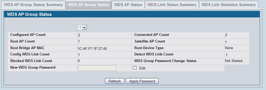
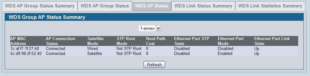
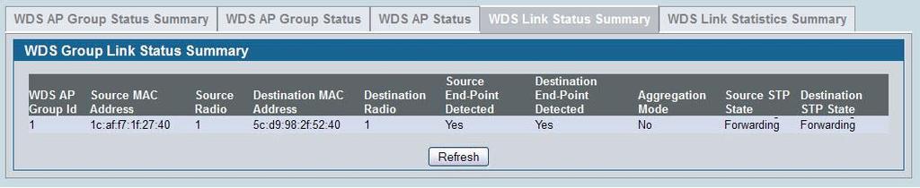
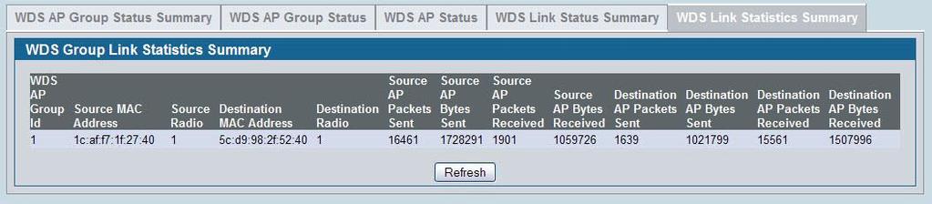
85 Page 85

86 8. Scenario 8 Configuring a Network to Use WPA2-Enterprise and Dynamic VLANs This scenario shows a company deploying a wireless network that uses WPA2-Enterprise encryption and dynamic VLANs. To keep financial information separate from other corporate data, the network administrator has configured a separate VLAN for Accounting Department employees. Because some individuals may be granted access to the Accounting VLAN for a short period, the administrator decides to use user-based granular control over VLAN assignments. The administrator controls access to the accounting VLAN by using a RADIUS server and Dynamic VLAN assignment. This example includes two wireless networks (VAPs): The Visitor network provides Internet access to guests. Guests who connect to the the Visitor network are assigned to VLAN 10, which provides limited access to network resources. The Corporate network is for employees. An employee who connects to this network must be authenticated by a network RADIUS server. By default, users on this network are assigned to VLAN 20. However, when an Accounting Department user authenticates to the Corporate network, the user is assigned to VLAN 30. The VLAN assignment in the RADIUS profile for an Accounting Department employee takes precedence over the default VLAN of the VAP. The following table shows a summary of the VAP configuration in this scenario: Table 15: VAP Information Network (SSID) VLAN Security Redirect Visitor 10 None Corporate 20 WPA Enterprise None In the following figure, when Client_1 initiates a connection to the Corporate network, the authentication information is passed from the client to the AP, and from the AP to the switch. Then, the switch forwards the information to the RADIUS server. If the authentication is successful, the RADIUS server response includes the VLAN assignment information This example includes only one AP, but the configuration is easily scalable to multiple APs. This scenario requires configuring settings on the RADIUS server and on the switch. Page 86
87 8.1 Configuring Client Information on the RADIUS Server To use WPA-Enterprise and RADIUS-assigned VLANs, you must configure information about the clients on the network RADIUS server. The configuration of your RADIUS server will vary depending on the manufacturer of the RADIUS server, but the parameters for dynamic VLAN tagging are the same, regardless of the RADIUS server you use. The following parameters should be set to allow for Dynamic VLAN Tagging where <vlan-id> is the VLAN to assign to each user. Tunnel-Type = 13, Tunnel-Medium-Type = 6, Tunnel-Private-Group-ID = <vlan-id> This example describes how to configure the FreeRADIUS server (available from FreeRADIUS.org) with the users in the following table: Table 16: RADIUS Users Username Password Group VLAN accountant accountant Accounting VLAN 30 engineer engineer Corporate None assigned To configure the FreeRADIUS server: 1. Edit the etc/raddb/users.conf file, which contains the user account information, and add the new users. The following code shows an example entry for the accountant and engineer users: accountant User-Password == "accountant" Tunnel-Type = 13, Tunnel-Medium-Type = 6, Tunnel-Private-Group-ID = 30 engineer User-Password == "engineer" 2. Edit the etc/raddb/clients.conf file to allow the switch to act as a client for the RADIUS server. The following code shows an example of the entry in the clients file that allows the switch to authenticate with the RADIUS server: client /24 { secret = secret12345 shortname = private-network-1 } The client network entry includes the IP address of the switch. The secret matches the secret to be configured on the switch. The secret must match on both systems. Page 87

, and enter the show network command to")
88 8.2 Configuring RADIUS Information and AP Profiles on the Switch The procedures in this section describe how to configure the RADIUS information on the switch, how to enable RADIUS-assigned VLANs, and how to configure the AP profile to be applied to the APs that the switch manages. 1. Connect to the web-based administration interface on the D-Link DWS-4000 Series switch. If you know the IP address of the switch, enter it into a browser to access the administration pages for the switch. If you do not know the IP address of the switch, connect to the console port (Baud rate: , Data: 8 bit, Parity: none, Stop: 1 bit, Flow control: none), and enter the show network command to view the switch IP address. 2. Configure the RADIUS server information. a. Go to the LAN > Security > RADIUS > RADIUS Authentication page. b. Configure the RADIUS server host address, for example c. Configure the RADIUS server name, for example RADIUS. d. Click Submit. Additional fields appear on the screen. e. To configure the password (shared secret) that the switch uses to authenticate with the RADIUS server, select the Apply option and type the password (for example secret12345) in the Secret field. The secret you configure must match the secret configured in the client entry for the switch on the RADIUS server. f. From the Primary Server field, select Yes. g. Click Submit. 3. Enable Dynamic VLAN creation mode to allow RADIUS-assigned VLANs to be automatically created on the switch if they do not already exist. a. Access the LAN > Security > Port Access Control page b. From the Dynamic VLAN Creation Mode menu, select Enable. Page 88


89 c. Click Submit. 4. Configure the Wireless Network Information for the Visitor network. a. Go to the WLAN > Administration > Basic Setup > SSID page. b. Select the radio to configure. This example configures Radio b/g/n. c. For Network 1 - dlink1, click Edit. d. Configure the following information in the appropriate fields: SSID = Visitor VLAN = 10 Redirect = HTTP Redirect URL = Page 89
 to return to the")

90 e. Click Submit. 5. Configure the Wireless Network Information for the Corporate network. a. Click the SSID tab (or click WLAN > Administration > Basic Setup > SSID) to return to the Wireless Default VAP Configuration page. b. Select the radio to configure. This example configures Radio b/g/n. c. Select the option next to Network 2- dlink2, and click Edit. Page 90

91 d. Configure the following information in the appropriate fields: SSID = Corporate VLAN = 20 Radius Authentication Server Name = RADIUS Security = WPA/WPA2, WPA Enterprise Note: The WPA Enterprise option is available only after you select the WPA/WPA2 option. 6. Add the AP to the Valid AP database so that it can become managed when the switch discovers it. a. Go to the WLAN > Administration > Basic Setup > Valid AP page. b. Specify the MAC address of the AP in the appropriate field. c. Optionally, specify the location or a name that identifies the AP, for example AP_1. Page 91

92 d. Click Add. When the AP becomes managed, the default profile is applied. If you make changes to the default profile after the AP is managed, you must reapply the profile to push the changes to the AP from the WLAN > Administration > Advanced Configuration > AP Profiles page. 8.3 Verifying the Configuration This section describes the pages available for monitoring information the managed AP and its associated clients. 1. Verify that the AP is now managed by the switch. Click WLAN > Monitoring > Access Point > Managed AP Status and verify that the AP_1 status is Managed and the Configuration status is Success. 2. Verify that the engineer user can connect to the Corporate network and is assigned to VLAN 20. a. Use a wireless client to access the wireless network with the Corporate SSID. b. When prompted for the username and password, enter engineer for both fields. Page 92


93 c. To verify the VLAN assigned to the engineer user, go to the WLAN > Monitoring > Client > Associated Clients page and select the MAC address of the client Note the VLAN of the engineer user is VLAN 20, the default VLAN for the VAP. 3. Verify that the accountant user can connect to the Corporate network and is assigned to VLAN 30. a. Use a wireless client to access the wireless network with the Corporate SSID. b. When prompted for the username and password, enter accountant for both fields. c. To verify the VLAN assigned to the engineer user, go to the WLAN > Monitoring > Client > Associated Clients page and select the MAC address of the client Note the VLAN of the accountant user is VLAN 30, which has been dynamically assigned by the RADIUS server. Page 93
94 9. Scenario 9 Optimizing WLAN Traffic The Unified Wired and Wireless Access System includes features that automatically help to optimize wireless traffic on the network. This section describes the following features: Automatic channel selection and adjustment on access point radios Automatic power adjustment for access point RF transmission power levels Per-radio load balancing to set the maximum utilization threshold By default, the automatic channel selection, automatic channel adjustment, and automatic power adjustment features are enabled but require manual triggers to run. Load balancing is disabled by default. This section describes ways to monitor the channel and power of the AP and to make manual adjustments, if necessary. It also describes how to enable the load balancing feature and monitor WLAN utilization. This section assumes that the switch has been configured and is currently managing multiple APs. 9.1 Monitoring and Managing Channel Information Interference can occur when multiple access points within range of each other are broadcasting on the same or overlapping channels. The impact of this interference on network performance can intensify during busy times when a large amount of data and media traffic is competing for bandwidth. When APs are within broadcast range of each other, the radios must use different channels to avoid causing RF interference. For the b/g radio, neighboring APs must operate on channels that are at least five channels apart. For example, if AP1 and AP2 are neighbors, AP1 can operate on channel 6 while AP2 operates on channel 11. Channels in the 5 GHz band (802.11a/n) do not overlap, so these channels interfere only if neighboring APs operate on the same channel. To avoid interference with neighbor APs, the Unified Wired and Wireless Access System uses an Initial Channel Selection (ICS) algorithm. When the AP is powered up the ISI algorithm scans all the available channels and counts the number of packets received on each channel. The best operating channel is considered to be the one with the lowest packet count, and this channel is assigned to the AP radio. Page 94
 on AP_1 is operating on channel 157, Radio 1 on AP_2 is operating on channel 44, and Radio 1 on AP_3 is operating on channel 36. Radio 2 (802.")
95 To view the channels that are assigned to managed APs, click WLAN > Monitoring > Access Point > Managed AP Status. As the following figure shows, Radio 1 (802.11a/n) on AP_1 is operating on channel 157, Radio 1 on AP_2 is operating on channel 44, and Radio 1 on AP_3 is operating on channel 36. Radio 2 (802.11b/g/n) on AP_1 is operating on channel 1, Radio 2 on AP_2 is operating on channel 6, and Radio 2 on AP_3 is operating on channel 11. For both radios, the operating channels for AP_1 do not interfere with the operating channels for AP_2. A second algorithm, the Auto Channel Adjustment (ACA) can periodically evaluate the operating channel and can automatically change the channel if the current operating channel is noisy. The cluster controller runs the ACA algorithm for the whole cluster. Non-cluster controller switches do not run the ACA algorithm. The setting to enable or disable the ACA algorithm is on the WLAN > Administration > Basic Settings > Radio page. Page 95
")
96 The ACA algorithm is enabled by default on each radio, but the default channel plan mode is manual. This means by default, the administrator must manually trigger the ACA algorithm. To configure the switch to run the ACA algorithm automatically, go to the WLAN > Administration > AP Management > RF Management page and configure the channel plan mode as Fixed Time (once per day) or Interval (once every 6 24 hours). Note: D-Link recommends that you run the ACA algorithm (either manually or periodically) when WLAN traffic is low because wireless clients must briefly disassociate from any radio that changes its channel. The following figure shows a channel plan that is configured to run at 3:15 AM every day Running and Applying a Manual Channel Plan The following procedures describe how to run and apply the channel plan manually. 1. Go to the WLAN > Administration > AP Management > RF Management page and note the Channel Plan Mode setting. The default mode is Manual. If the mode is Fixed Time or Interval, you cannot run the ACA algorithm manually. Page 96


97 2. Click the Manual Channel Plan tab. 3. Select the radio to run the channel plan on, and then click Start. 4. To view the channel plan that the ACA algorithm recommends, click Refresh. The following figure shows that the ACA algorithm determined that the best operating channel for Radio 1 on AP_3 is channel 149, and not its current operating channel. Note: If the ACA algorithm determines that the APs are currently operating on the best channel, the Current Status field reports Algorithm Complete: No Change Required. 5. To apply the suggested channel plan, click Apply. Note: D-Link recommends that you apply the channel plan when WLAN traffic is low. When a radio changes to a different channel, any associated clients are forced to disassociate and reassociate. 6. To view information about the channel plans that have been applied, click the Channel Plan History tab. Page 97
98 7. To view the operating channel for AP_3 and all managed APs, go to the WLAN > Monitoring > Access Point > Managed AP Status page. 9.2 Monitoring the RF Transmission Power Level The RF signal transmission power level directly affects the broadcast range of the AP signal. If the power level is too low, wireless clients will not detect the signal or experience poor WLAN performance. If the power level is too high, the RF signal might interfere with other APs within range. If the RF signal broadcasts beyond the physical confines of your building or network, it increases the security threat to the network. The Automatic Power Adjustment algorithm works by setting the initial power of the AP to the value specified in the AP profile. The power is then periodically adjusted to a level based on the presence or absence of packet transmission errors. The power is changed in increments of 10%. The Automatic Power Adjustment feature is enabled by default. However, by default the algorithm is triggered manually, and not at a fixed interval. Note: The algorithm never reduces the AP power below the initial power setting as specified in the profile, and since the default power level in the default profile is 100%, the power would never be reduced unless this value is first changed. Page 98

99 9.2.1 Configuring the Automatic Power Adjustment This example describes how to run and apply the Automatic Power Adjustment (APA) algorithm. 1. To adjust the initial power level setting on the AP profile, go to the WLAN > Administration > Basic Settings > Radio page and set the Initial Power field to a percentage lower than 100, for example 60%. 2. Click Submit. 3. Optionally, select Radio 2 and configure the Initial Power setting, and then click Submit. 4. If the APs are already managed, use the following steps to reapply the profile so the new settings take effect: a. Go to the WLAN > Administration > Advanced Configuration > AP Profiles page. b. Select the check box next to the profile you modified. c. Click Apply. Page 99

100 A message appears and indicates that the AP radios will be reset, which will disassociate any associated wireless clients. Click OK to continue. 5. View the transmit power for the associated APs by clicking WLAN > Monitoring > Access Points > Managed AP Status > Radio Summary. 6. Go to the WLAN > Administration > AP Management > RF Management page and note the Power Adjustment Mode setting. The default mode is Manual. If the mode is Interval, you cannot run the APA algorithm manually. 7. Click the Manual Power Adjustment tab. 8. Click Start to allow the algorithm to run and determine whether any power adjustments are appropriate. 9. To view the adjustments that the APA algorithm recommends, click Refresh. Note: The APA recommends power adjustments based on the presence or absence of packet transmission errors. A high number of packet transmission errors indicates that the signal strength might be too low and that wireless clients are unable to successfully transmit traffic. If no wireless clients are connected to the AP, no power adjustments will be recommended. Page 100

101 The following figure shows that the APA algorithm detected a high number of transmission errors on AP_2, and that the power level should be increased by 10% to increase the transmission area. 10. To apply the recommendation and allow the AP to adjust its transmission power level, click Apply. 11. Verify that the power level has been adjusted by viewing the WLAN > Monitoring > Access Points > Managed AP Status > Radio Summary page. 9.3 Load Balancing and WLAN Utilization When the power level on an access point is high and the RF broadcast area is large, more wireless clients can detect the signal and associate with the AP than when the power is low and the broadcast area is small. However, an increase in the number of wireless clients that associate with the AP generally means that the amount of traffic the AP receives and transmits increases as well, which can impact wireless network speed and performance. You can limit the network utilization level allowed on an AP to prevent wireless clients from experiencing slower network speeds. Once the network utilization is reached, new clients are unable to associate with the AP. However, the wireless client might be able to associate with a neighboring AP if it is within range. If an AP frequently reaches the network utilization limit, it might indicate that you should add another AP nearby. For each AP profile, you can enable and configure load balancing on a per radio basis. You can also monitor WLAN utilization for each AP and switch within the Unified Wired and Wireless Access System. Page 101

102 By monitoring the WLAN utilization information for the FASTPATH Unified Wireless System and for specific switches and APs within the system, you can make informed decisions about where to place additional APs or make adjustments in AP placement and power transmission levels. To configure load balancing and monitor WLAN utilization: 1. Go to the WLAN > Administration > Basic Setup > Radio page and select the radio to configure. 2. Select the Load Balancing check box to enable load balancing. 3. Specify the threshold for the percentage of network bandwidth utilization allowed on the radio. Once the level you specify is reached, the AP stops accepting new client associations. 4. Click Submit to apply the changes to the selected radio. 5. If the APs are already managed, use the following steps to reapply the profile so the new settings take effect: a. Go to the WLAN > Administration > Advanced Configuration > AP Profiles page. b. Select the check box next to the profile you modified. c. Click Apply. Page 102


103 A message appears and indicates that the AP radios will be reset, which will disassociate any associated wireless clients. Click OK to continue. 6. To monitor the current WLAN utilization rate for a radio, go to the WLAN > Monitoring > Access Point > Managed AP Status > Radio Detail page and select the AP (listed by MAC address) and its radio. The WLAN Utilization field displays the current traffic load that the radio is bearing based on the total possible percentage of traffic that the radio can handle. 7. To monitor the current WLAN utilization rate for the FASTPATH Unified Wireless System, go to the WLAN > Monitoring > Global page and view the WLAN Utilization field. 8. If the FASTPATH Unified Wireless System includes multiple switches in a cluster, click the Switch Status tab to view WLAN Utilization information for an individual switch within the cluster. Page 103
104 10. Scenario 10 Detecting and Preventing Wireless Intrusion This section describes how to use of some of the Wireless Intrusion Detection System (WIDS) and Wireless Intrusion Prevention System (WIPS) functions on the D-Link Unified Wireless Switch. In this example, a company has configured a wireless network with the VAPs shown in the following table: Table 17: VAPs for Intrusion Prevention/Detection Network (SSID) VLAN Security Redirect Visitor 10 None Corporate 20 WPA Enterprise None As an additional security measure, the network administrator has decided to employ the use of the WIDS/WIPS functionality to further protect the corporate network. The examples in this section show how to configure the Unified Switch and how to monitor the system as it mitigates potential security risks in the wireless domain Configuring a Radio in Sentry Mode To implement the security policies of the company in this example, the second radio on the Access Point DWL-8600 is configured in sentry mode to scan for violations of the WIDS tests. Alternately, separate APs can be configured as dedicated sentry APs. When a radio operates in sentry mode, the radio performs a continuous radio scan. In sentry mode, no beacons are sent, and no clients are allowed to associate with the AP through the sentry radio. If a dedicated sentry radio or AP is not configured, the active radios still scan other channels but will do so at a slower rate than a radio in sentry mode. The rate at which a radio scans the RF traffic is important to WLAN security because slower scanning allows Rogue APs to remain undetected for a longer period of time. To enable sentry mode in the default profile on radio 1: 1. Click WLAN > Administration > Basic Setup > Radio to access the Wireless Default Radio Configuration page. 2. Select Radio Select the RF Scan Sentry option. Note: By default, the sentry radio scans a and g/b channels. To configure the sentry radio to scan only a or b/g channels, but not both, click WLAN > Page 104

105 Administration > Advanced Configuration > AP Profiles > Profile Name > Radio to access the Access Point Profile Radio Configuration page for the selected profile. 4. Click Submit to apply the changes to the running configuration on the switch. Note that the label for radio 1 changes to Sentry. 5. If an AP is already managed, use the following steps to reapply the profile so the new settings take effect: a. Go to the WLAN > Administration > Advanced Configuration > AP Profiles page. b. Select the check box next to the profile you modified. c. Click Apply Configuring and Monitoring WIDS/WIPS to Detect Rogue APs All passive WIDS detection algorithms for APs are enabled by default on the Unified Switch. The tests are passive because they can detect and report rogue APs and clients but do not attempt to prevent these devices from interfering with the network. It the responsibility of the administrator to monitor the WIDS test results and take action against potential rogue devices. To view and configure the WIDS and WIPS parameters click WLAN > Administration > Advanced Configuration > WIDS Security. Page 105

106 The following figure shows the default values on the WIDS configuration page for the AP. To demonstrate the WIDS and WIPS capabilities of the DWS-4000 Series switch, in this scenario a hacker has set up a Honeypot AP in the parking lot of the company's building. This AP is configured with the SSID Corporate to try to get valid clients from inside the company to associate to it in an attempt to gather passwords and other confidential information that will allow the hacker to gain further access to the company's resources. As the figure shows, most clients have authenticated with the legitimate AP within the company. However, one client within the company has unknowingly associated with the honeypot AP that is physically located outside the walls of the company. Page 106


107 In this situation, the WIDS system on the AP automatically tags the honeypot AP as a Rogue on the WLAN > Monitoring > Access Point > All AP Status page. Click the MAC address of the rogue AP to view additional information about the AP. Click the WIDS AP Rogue Classification tab to learn which WIDS test triggered the rogue status. As the figure above shows, the honeypot AP is identified as a rogue because it triggered the Managed SSID from an unknown AP test. In other words, the honeypot AP, which is an unknown AP to the company, is using the same SSID as the legitimate AP inside the building. At this point, no further action is taken by the DWS-4000 Series switch because the AP deauthentication attack feature is disabled. To enable the AP to take further action, Page 107

108 enable the AP De-Authentication Attack option on the WLAN > Administration > Advanced Configuration > WIDS Security tab. When the AP De-Authentication Attack is configured, the WIDS AP Rogue AP Mitigation field on the AP RF Scan Status page shows that the mitigation is in progress. You can also track the progress of the deauthentication attack on the WLAN > Monitoring > Access Point > AP De-Authentication Attack Status page. Page 108

109 The AP deauthentication attack causes deauthentication frames to be sent to the rogue AP and to clients communicating with the rogue AP. All clients connected to the rogue AP will experience poor connectivity. The intent of the attack is to serve as a temporary measure until the rogue AP is located and disabled. Note: Radios in non-sentry mode transmit deauthentication frames only on their active channel. Therefore, D-Link recommends that you deploy radios in sentry mode to effectively implement rogue AP deauthentication attacks. Caution: The deauthentication attack interrupts communication between all APs designated as rogue and their stations. Therefore, it is important to make sure all rogue APs are truly rogue before initiating this attack Using WIDS/WIPS to Detect Rogue Clients In addition to targeting Rogue APs, the DWS-4000 Series switch supports client-based security detection algorithms to help monitor and control wireless clients on the network. To view and configure the WIDS and WIPS parameters for wireless clients, click WLAN > Administration > Advanced Configuration > WIDS Security > Client Configuration. The following figure shows the default values on the WIDS configuration page for the client. Page 109


110 If a client exhibits suspicious behavior by triggering a test or exceeding the acceptable threshold values configured on the page, it is marked as Rogue. To view information about all detected clients, click WLAN > Monitoring > Client > Detected Clients. Click the MAC address of the client to access additional information, including the client s rogue classification. The following figure shows a client that is identified as a rogue because the Authentication Failure Threshold Value configured on the WIDS Client Configuration page shown in the figure is five, and the client has failed the authentication 12 times. Click the Rogue Classification tab to view information about why the client is classified as a rogue. The WIDS client rogue classification information indicates that either the user has forgotten his password, or perhaps someone is trying to guess a password to gain access to the network. The network administrator should investigate further. Implementing features such as WLAN Visualization and the Device Locator can help locate the rogue client. Page 110

111 10.4 Mitigating a Rogue Client Threat In this scenario, the network administrator for a retail store is implementing Rogue Client Threat Mitigation to provide additional security in her store located in a shopping mall. Several tablet PCs are used to track inventory within the establishment. The network administrator decides to use Client Threat Mitigation to make sure that these tablets are associated only with company-controlled APs. This scenario uses Client Threat Mitigation rather than the AP De-Authentication Attack for the following reasons: Using AP Mitigation would be difficult because the administrator has no control over APs in adjoining stores, and keeping up with changes in APs located in other stores might create too much overhead. If the administrator were to accidentally classify a neighboring store's AP as Rogue and jam the other store's traffic, she could potentially be liable for interrupting the business of the adjacent store. Employees can be prevented from using the tablet PCs to access public networks for non work-related functions or to circumvent corporate firewalls, which could expose company data. Note: Radios in non-sentry mode will not transmit Client Threat Mitigation frames. Therefore, sentry radios must be deployed for the network administrator to use this feature. To add the clients that are allowed to access the network into the Known Client Database and configure the Client Threat Mitigation feature: 1. Verify the MAC Authentication mode is white-list on the WLAN > Administration > Advanced Configuration > Global page. The white-list authentication mode means that wireless clients with MAC addresses that are specified in the Known Client database, and are not explicitly denied access, are granted access. If the MAC address is not in the database then the access to the network is denied. Page 111


112 2. On the WLAN > Administration > Advanced Configuration > Clients > Known Clients page, type the MAC addresses of a tablet PC into the available field. 3. Click Add. The Known Client Configuration page appears. The default authentication action is Global Action, which means the switch uses the white-list authentication mode as specified on the Wireless Global Configuration page. Only the MAC addresses in the Known Client database are marked as Known Clients. 4. Specify a name to identify the client in the Name field 5. Click Submit. 6. Repeat On the Click until all allowed clients are in the Known Clients database. 7. To configure the client-based WIDS security tests and enable the client threat mitigation feature, go to the WLAN > Administration > Advanced Configuration > WIDS Security > Client Configuration page and configure the following settings: a. Set the Known Client Database Test to Enable b. Set Authentication with Unknown AP Test to Enable c. Set Client Threat Mitigation to Enable Page 112

113 8. View information about all detected clients on the WLAN > Monitoring > Client > Detected Clients page. In the following figure, the Known Client is shown as Authenticated while it is associated to the Corporate SSID. Other detected clients have failed the Known Clients Database test and are listed as Rogue. Note: If the client status for some clients stays as Detected, check the age of the connection. Rogue classification is performed only on current clients and only when the Known Clients Database Test is enabled. Clients that existed in the Detected Clients database prior to the activation of the Known Clients Database Test and are no longer present will not be tagged as Rogue. If an employee using Tablet_5 attempts to use an unknown AP with one of the tablets, the DWS-4000 Series switch initiates a Client Threat Mitigation attack. The WLAN > Monitoring > Client > Detected Clients page shows that the Tablet_5 client now has a client status of Rogue. Click the MAC address of the client to display the client s Detected Client Status page. Page 113
114 As the following figure shows, the client is detected as a threat, and the threat mitigation feature caused the AP to send a deauthentication request to the client. Traffic transmitted by the rogue tablet is interrupted, and it is not able to remain associated with the unknown AP. Click the Rogue Classification tab to confirm the WIDS security test results for the client. Page 114
115 11. Appendix 1. Use the following settings to make a console connection: Select the appropriate serial port (COM port 1 or COM port 2). Set the data rate to baud. Set the data format to 8 data bits, 1 stop bit, and no parity. Set flow control to none. Under Properties, select VT100 for Emulation mode. 2. The CLI commands of DWS-4000 series are more Cisco-Like: Enter admin as the default username. There is no default password; press Enter at the password prompt. 3. The first level of system access is User EXEC mode. The User EXEC mode contains a limited set of commands to view basic system information. See Table 18 on page 116 for the command prompt, mode access and exit. Enter a question mark (?) at the command prompt to display the commands available in the current mode. 4. Command completion finishes spelling the command when you type enough letters of a command to uniquely identify the command keyword. Once you have entered enough letters, press the SPACEBAR or TAB key to complete the word. 5. From the User EXEC mode, enter enable to get into the second level of system access - Privileged EXEC mode. There is no default password; just press Enter at the password prompt. The Privileged EXEC mode allows you to enter any EXEC command or enter the Global Configuration mode. Following are some useful Privileged EXEC commands for the listed scenarios: show network show vlan port all show ip interface brief show wireless ap status show wireless ap failure status See Table 18 on page 116 for the command prompt, mode access and exit. Enter a question mark (?) at the command prompt to display the commands available in the current mode. 6. From the Privileged EXEC mode, enter configure to get into Global Config mode. Global Config mode groups general setup commands and permits you to make modifications to the running configuration. See Table 18 on page 116 for the command prompt, mode access, and exit. Page 115
 # From the User EXEC mode, enter enable.")
116 Table 18 CLI Command Modes Access and Exit Command Mode Prompt Access Method Exit or Access Previous Mode User EXEC (DWS-4024) > This is the first level of To exit, enter logout. access. Privileged EXEC (DWS-4024) # From the User EXEC mode, enter enable. To exit to User EXEC mode, enter exit or Global Config (DWS- 4024)(Config)# From the Privileged EXEC mode, enter configure press Ctrl-Z. To exit to the Privileged EXEC mode, enter exit or press Ctrl-Z. 7. You can log on to and to Product Data/ Switch/ Switch/ DWS-4000 Series, to find the latest firmware of Unified Switch as well as AP. Also available is for reference is the manual of Web GUI & CLI commands. 8. When you upgrade the Unified Switch, you need to upgrade Access Point as well. Refer to the upgrade instructions along with the firmware on PMD. 9. For more information regarding the deployment in the overlay structure, refer to the coming white paper on PMD. The white paper will describe different deployment topologies and items you need to notice. 10. In case you cannot achieve the ideal results through manual configuration, D-LINK provides sample configuration files for all scenarios (file names are DWS-4024-SCN1-1018, DWS-4024-SCN2-1018, DWS-4024-SCN3-1018, DWS SCN4-1018, DWS SCN respectively; two configurations for Scenario 4 for two Unified Switches) so that you can still proceed to the tests. Download the configuration file by selecting Download File in the tool bar list. Page 116
 d. Type the filename in TFTP File Name. e. Select the Start File Transfer option. f. Click the Submit button. g.")
117 a. Select Configuration for the File Type. b. Type your PC s IP address in TFTP Server Address. c. Type the filepath in TFTP File Path. (Note: This is not needed if in the root directory of the TFTP Server.) d. Type the filename in TFTP File Name. e. Select the Start File Transfer option. f. Click the Submit button. g. After successfully downloading, the configuration is automatically applied to the switch. Page 117
Add a Wireless Network to an Existing Wired Network using a Wireless Access Point (WAP)
") Add a Wireless Network to an Existing Wired Network using a Wireless Access Point (WAP) Objective A Wireless Access Point (WAP) is a networking device that allows wireless-capable devices to connect to
Add a Wireless Network to an Existing Wired Network using a Wireless Access Point (WAP) Objective A Wireless Access Point (WAP) is a networking device that allows wireless-capable devices to connect to
UNIFIED ACCESS POINT ADMINISTRATOR S GUIDE
 UNIFIED ACCESS POINT ADMINISTRATOR S GUIDE PRODUCT MODEL: DWL-2600AP, DWL-3600AP, DWL-6600AP, DWL-8600AP, DWL-8610AP UNIFIED WIRED & WIRELESS ACCESS SYSTEM RELEASE 5.00 OCTOBER 2014 COPYRIGHT 2014. ALL
UNIFIED ACCESS POINT ADMINISTRATOR S GUIDE
 UNIFIED ACCESS POINT ADMINISTRATOR S GUIDE PRODUCT MODEL: DWL-2600AP, DWL-3600AP, DWL-3610AP, DWL-6600AP, DWL-6610AP, DWL-6610APE, DWL-6700AP, DWL-8600AP, DWL-8610AP, DWL-8710AP,DWL-6620APS, DWL-7620AP
Grandstream Networks, Inc. GWN76xx Wi-Fi Access Points Master/Slave Architecture Guide
 Grandstream Networks, Inc. GWN76xx Wi-Fi Access Points Master/Slave Architecture Guide Table of Contents INTRODUCTION... 4 DISCOVER AND PAIR GWN76XX ACCESS POINTS... 5 Discover GWN76xx... 5 Method 1: Discover
Release Notes for Avaya WLAN 9100 AOS-Lite Operating System WAP9112 Release WAP9114 Release 8.1.0
 WLAN 9100 Release Notes Release Notes for Avaya WLAN 9100 AOS-Lite Operating System WAP9112 Release 8.1.0 WAP9114 Release 8.1.0 Avaya Inc - External Distribution 1. Introduction This document provides
Document Created by Nick Schuster
 Document Created by Nick Schuster Table of Contents Product Overview... 4 Introduction... 4 Features... 5 Package Contents... 6 System Requirements... 6 Hardware Overview... 7 LEDs... 7 Connections...
WAP9112/9114 Quick Start Guide
 WAP9112/9114 Quick Start Guide Release 7.6 NN47252-308 Issue 02.01 March 2016 Contents Chapter 1: Introduction... 3 Chapter 2: Required Software Components... 4 Chapter 3: Installing or Upgrading Wireless
Configuring a VAP on the WAP351, WAP131, and WAP371
 Article ID: 5072 Configuring a VAP on the WAP351, WAP131, and WAP371 Objective Virtual Access Points (VAPs) segment the wireless LAN into multiple broadcast domains that are the wireless equivalent of
EnGenius Quick Start Guide
 T he operates seamlessly in the 2.4 GHz frequency spectrum supporting the 802.11b (2.4GHz, 11Mbps) and the newer, faster 802.11g (2.4GHz, 54Mbpswireless standard. High output power and high sensitivity
LevelOne. User Manual. WAP Mbps PoE Wireless AP V3.0.0
 LevelOne WAP-0005 108Mbps PoE Wireless AP User Manual V3.0.0 i TABLE OF CONTENTS CHAPTER 1 INTRODUCTION... 1 FIGURE 1: WIRELESS ACCESS POINT... 1 FEATURES OF YOUR WIRELESS ACCESS POINT... 1 Security Features...
NXC Series. Handbook. NXC Controllers NXC 2500/ Default Login Details. Firmware Version 5.00 Edition 19, 5/
 NXC Series NXC 2500/ 5500 NXC Controllers Firmware Version 5.00 Edition 19, 5/2017 Handbook Default Login Details LAN Port IP Address https://192.168.1.1 User Name admin Password 1234 Copyright 2017 ZyXEL
Document Created by Nick Schuster
 Document Created by Nick Schuster Table of Contents Product Overview... 4 Introduction... 4 Features... 5 Package Contents... 6 System Requirements... 6 Hardware Overview... 7 LEDs... 7 Connections...
Wireless AC1200 Concurrent Dual Band PoE Access Point
 DAP-2660 Version 1.00 AirPremier Wireless AC1200 Concurrent Dual Band PoE Access Point Product Overview...5 Introduction... 5 Features... 6 Package Contents... 7 System Requirements... 7 Hardware Overview...8
FortiNAC. Aerohive Wireless Access Point Integration. Version 8.x 8/28/2018. Rev: E
 FortiNAC Aerohive Wireless Access Point Integration Version 8.x 8/28/2018 Rev: E FORTINET DOCUMENT LIBRARY http://docs.fortinet.com FORTINET VIDEO GUIDE http://video.fortinet.com FORTINET KNOWLEDGE BASE
Document Created by Nick Schuster
 Document Created by Nick Schuster Product Overview...4 Introduction... 4 Features... 5 Package Contents... 6 System Requirements... 6 Hardware Overview...7 LEDs... 7 Connections... 7 Basic Installation...8
Configuring Hybrid REAP
 13 CHAPTER This chapter describes hybrid REAP and explains how to configure this feature on controllers and access points. It contains the following sections: Information About Hybrid REAP, page 13-1,
Siemens HiPath Wireless: Configuration and Deployment Guide
 Siemens HiPath Wireless System Configuration and Deployment Guide SpectraLink's Voice Interoperability for Enterprise Wireless (VIEW) Certification Program is designed to ensure interoperability and high
Extreme Networks Summit WM-Series Wireless Controller and Altitude APs Configuration and Deployment Guide
 Extreme Networks Summit WM-Series Wireless Controller and Altitude 350-2 APs Configuration and Deployment Guide SpectraLink's Voice Interoperability for Enterprise Wireless (VIEW) Certification Program
D-Link Wireless Aware Smart Switching System Configuration Guide. Wireless Aware Smart Switching System
 Wireless Aware Smart Switching System 1 Table of Contents Table of Contents... 2 Introduction... 3 System Requirement... 3 Scenario 1 - Basic Setup... 3 1.1 Enable the Wireless Awareness Function... 4
User Guide. Omada Controller Software
 User Guide Omada Controller Software 1910012394 REV 2.7.0 July 2018 CONTENTS 1 Quick Start... 1 1.1 Determine the Network Topology...2 1.1.1 Management in the Same Subnet... 2 1.1.2 Management in Different
CONFIGURING AND DEPLOYING THE AX411 WIRELESS ACCESS POINT
 APPLICATION NOTE CONFIGURING AND DEPLOYING THE AX411 WIRELESS ACCESS POINT Copyright 2009, Juniper Networks, Inc. 1 Table of Contents Introduction......................................................................................................3
User Guide. Omada Controller Software
 User Guide Omada Controller Software 1910012506 REV 3.2.0 March 2019 CONTENTS 1 Quick Start... 1 1.1 Determine the Network Topology...2 1.1.1 Management on the local Network... 2 1.1.2 Management via Cloud
Configuring OfficeExtend Access Points
 Information About OfficeExtend Access Points, page 1 OEAP 600 Series Access Points, page 2 OEAP in Local Mode, page 3 Supported WLAN Settings for 600 Series OfficeExtend Access Point, page 3 WLAN Security
D-Link DSR Series Router
 D-Link DSR Series Router U s e r M a n u a l Copyright 2010 TeamF1, Inc. All rights reserved Names mentioned are trademarks, registered trademarks or service marks of their respective companies. Part No.:
TECHNICAL NOTE UWW & CLEARPASS HOW-TO: CONFIGURE UNIFIED WIRELESS WITH CLEARPASS. Version 2
 HOW-TO: CONFIGURE UNIFIED WIRELESS WITH CLEARPASS Version 2 CONTENTS Introduction... 7 Background information... 7 Requirements... 7 Network diagram... 7 VLANs... 8 Switch configuration... 8 Initial setup...
Configuring WDS, Fast Secure Roaming, Radio Management, and Wireless Intrusion Detection Services
 CHAPTER 11 Configuring WDS, Fast Secure Roaming, Radio Management, and Wireless Intrusion Detection Services This chapter describes how to configure your access point/bridges for wireless domain services
Siemens HiPath Wireless: Configuration and Deployment Guide
 Siemens HiPath Wireless System Configuration and Deployment Guide SpectraLink's Voice Interoperability for Enterprise Wireless (VIEW) Certification Program is designed to ensure interoperability and high
Procedure: You can find the problem sheet on the Desktop of the lab PCs.
 University of Jordan Faculty of Engineering & Technology Computer Engineering Department Computer Advance Networks Laboratory 907529 Lab.3 WLAN Security Objectives 1. Configure administrator accounts.
Table of Contents. Product Overview...4 Package Contents...4 System Requirements...4 Introduction...5 Features...7
 Table of Contents Table of Contents Product Overview...4 Package Contents...4 System Requirements...4 Introduction...5 Features...7 Wireless Basics...8 Standards-Based Technology...9 Wireless Installation
WAP3205 v2. User s Guide. Quick Start Guide. Wireless N300 Access Point. Default Login Details. Version 1.00 Edition 2, 12/2012
 WAP3205 v2 Wireless N300 Access Point Version 1.00 Edition 2, 12/2012 Quick Start Guide User s Guide Default Login Details LAN IP Address http://192.168.1.2 Password 1234 www.zyxel.com Copyright 2012 ZyXEL
Quick Install & Troubleshooting Guide. WAP223NC Cloud Managed Wireless N Access Point
 Quick Install & Troubleshooting Guide WAP223NC Cloud Managed Wireless N Access Point Package Contents 1 x WAP223NC Indoor access point powered by CloudCommand 1 x wall and ceiling mounts 1 x 24V PoE power
Wireless Access Point
 802.11g / 802.11b / WPA Wireless Access Point User's Guide TABLE OF CONTENTS CHAPTER 1 INTRODUCTION... 1 Features of your Wireless Access Point... 1 Package Contents... 4 Physical Details... 4 CHAPTER
LP-2396K Outdoor 2.4GHz Wireless AP/CPE/Bridge
 User Manual LP-2396K Outdoor 2.4GHz Wireless AP/CPE/Bridge 1 Table of Contents 1. Introduction... 3 1.1 Product Introduction... 4 1.2 Package Content... 5 1.3 Product Features... 6 1.4 Application... 6
Insight Managed Smart Cloud Wireless Access Point User Manual
 Insight Managed Smart Cloud Wireless Access Point User Manual Model WAC510 September 2017 202-11840-01 350 E. Plumeria Drive San Jose, CA 95134 USA Support Thank you for purchasing this NETGEAR product.
Oct 2007 Version 1.01
 Oct 2007 Version 1.01 Table of Contents Introduction...4 System Requirement...4 Getting Started...4 Installing the Smart WLAN Manager...5 Discovering the Switch and AP...9 Understanding the Screen Layout...12
Vendor: HP. Exam Code: HP2-Z32. Exam Name: Implementing HP MSM Wireless Networks. Version: Demo
 Vendor: HP Exam Code: HP2-Z32 Exam Name: Implementing HP MSM Wireless Networks Version: Demo QUESTION 1 A network administrator deploys several HP MSM APs and an HP MSM Controller. The APs discover the
Chapter 1 Introduction
 Copyright Statement is the registered trademark of Zonet Technology Inc. All the products and product names mentioned herein are the trademarks or registered trademarks of their respective holders. Copyright
AirCruiser G Wireless Router GN-BR01G
 AirCruiser G Wireless Router GN-BR01G User s Guide i Contents Chapter 1 Introduction... 1 Overview...1 Features...1 Package Contents...2 AirCruiser G Wireless Router Rear Panel...2 AirCruiser G Wireless
AC WiFi Business Access Point WAC510 User Manual
 AC WiFi Business Access Point WAC510 User Manual with NETGEAR Insight app for easy management December 2016 202-11686-01 350 E. Plumeria Drive San Jose, CA 95134 USA Support Thank you for purchasing this
Insight Managed Smart Cloud Wireless Access Point User Manual
 Insight Managed Smart Cloud Wireless Access Point User Manual Model WAC505 February 2018 202-11757-03 350 E. Plumeria Drive San Jose, CA 95134 USA Support Thank you for purchasing this NETGEAR product.
Preface. Manual Revisions. Revision Date Description 1.0 March 3, 2009 DAP-3520 Revision A1 with firmware version Trademarks
 Preface D-Link reserves the right to revise this publication and to make changes in the content hereof without obligation to notify any person or organization of such revisions or changes. Manual Revisions
300Mbps Wireless N Gigabit Ceilling Mount Access Point
 Datasheet 300Mbps Wireless N Gigabit Ceilling Mount Access Point 120 Highlights Wireless N speed up to 300Mbps The Controller Software enables administrators to manage hundreds of s easily from any PC
A5500 Configuration Guide
 A5500 Configuration Guide Sri Ram Kishore February 2012 Table of contents Gateway Configuration... 3 Accessing your gateway configuration tool... 3 Configuring your broadband Internet access... 3 Configuring
300Mbps Wireless N Ceiling Mount Access Point
 Datasheet Ceiling Mount Access Point 110 Highlights Wireless N speed up to 300Mbps Controller Software enables administrators to easily manage hundreds of s Supports passive PoE for convenient installation
A connected workforce is a more productive workforce
 A connected workforce is a more productive workforce D-Link wireless networking solutions enable business networks of all sizes to create highly mobile, highly productive work environments at a low total
Configuration Guide. Wireless Controller AC50/AC500
 Configuration Guide Wireless Controller AC50/AC500 1910012437 REV1.0.2 June 2018 Content About This Guide... 1 1 Quick Start... 2 1.1 Determine the Network Topology... 2 1.1.1 Manage CAPs in the LAN...2
Wireless-N USB Adapter User s Manual
 Wireless-N USB Adapter User s Manual Copyright 2007 EUSSO Technologies, Inc. All rights reserved. Table of Contents PREFACE... 3 WIRELESS LAN BASICS... 3 Warning... 3 INSTALLATION OVERVIEW... 4 INTRODUCTION...
Configuring the EAPs Separately via Omada Controller
 Configuring the EAPs Separately via Omada Controller CHAPTERS 1. View the Information of the EAP 2. View Clients Connecting to the EAP 3. This guide applies to: Omada Controller 2.6.0. In addition to global
Wireless Controller DWC-1000
 Network Architecture Manage up to 6 wireless APs, upgradable to 24 APs 1 per controller Control up to 24 wireless APs, maximum 96 APs 1 per cluster Robust Network Security Wireless Instruction Detection
Table of Contents. Table of Contents
 Table of Contents Product Overview... 4 Package Contents... 4 System Requirements... 4 Introduction... 5 Features and Benefits... 6 Wireless Basics... 7 Four Operational Modes... 10 Getting Started...
WISNETWORKS. WisOS 11ac V /3/21. Software version WisOS 11ac
 WISNETWORKS User Manual V1.1 2016/3/21 Software version 1.0.0021 Table of contents 1. Setup& WMI... 3 1.1 Hardware Setup... 3 1.2 Web Management Interface... 3 2. Status... 4 2.1 Overview... 4 2.1.1 System...
WFS709TP Case Scenario: Wireless deployment for a Corporate and Public network
 WFS709TP Case Scenario: Wireless deployment for a Corporate and Public network This document describes the activities undertaken to deploy a Wireless solution using the Wireless Controller WFS709TP and
IEEE a/b/g/n Wireless LAN Access Point. AT-MWS AP series. Reference Manual
 IEEE 802.11a/b/g/n Wireless LAN Access Point AT-MWS AP series Reference Manual Table of Contents 1 Before You Begin 5 1.1 Considerations for Wireless Installation...6 Computer Settings...6 Hardware Installation...9
Security SSID Selection: Broadcast SSID:
 69 Security SSID Selection: Broadcast SSID: WMM: Encryption: Select the SSID that the security settings will apply to. If Disabled, then the device will not be broadcasting the SSID. Therefore it will
Quick Start Guide for Standalone EAP
 Quick Start Guide for Standalone EAP CHAPTERS 1. Determine the Management Method 2. Build the Network Topology 3. Log In to the EAP 4. Edit the SSID 5. Configure and Manage the EAP This guide applies to:
EnGenius M2000 Wireless Outdoor Access Point / Client Bridge / Mesh User Manual Version: 1.0
 EnGenius M2000 Wireless Outdoor Access Point / Client Bridge / Mesh User Manual Version: 1.0 Table of Contents 1 INTRODUCTION... 6 1.1 FEATURES... 6 1.2 PACKAGE CONTENTS... 7 1.3 SYSTEM REQUIREMENTS...
300Mbps Wireless N Gigabit Ceilling Mount Access Point
 Datasheet 300Mbps Wireless N Gigabit Ceilling Mount Access Point Highlights Wireless N speed up to 300Mbps Clustering function greatly simplified business wireless network management, to easy manage up
Table of Contents Package Contents Introduction Features and Benefits Wireless Basics Three Operational Modes...
 Table of Contents Table of Contents Table of Contents... 2 Package Contents... 3 Introduction... 4 Features and Benefits... 6 Wireless Basics... 7 Three Operational Modes... 10 Getting Started... 11 Using
300Mbps Wireless N Gigabit Ceilling Mount Access Point
 Datasheet 300Mbps Wireless N Gigabit Ceilling Mount Access Point 120 Highlights Wireless N speed up to 300Mbps The Controller Software enables administrators to manage hundreds of s easily from any PC
Using the Web Graphical User Interface
 Prerequisites for Using the Web GUI, page 1 Information About Using The Web GUI, page 2 Connecting the Console Port of the Switch, page 3 Logging On to the GUI, page 4 Enabling Web and Secure Web Modes,
WRE2206. User s Guide. Quick Start Guide. Wireless N300 Range Extender. Default Details. Version 1.00 Edition 1, 01/2015
 WRE2206 Wireless N300 Range Extender Version 1.00 Edition 1, 01/2015 Quick Start Guide User s Guide Default Details Web Address http://zyxelsetup OR http://192.168.1.2 www.zyxel.com User Name admin Password
A Division of Cisco Systems, Inc. GHz 2, g. Wireless-G. User Guide. Access Point WIRELESS WAP54G (EU/LA/UK) Model No.
 Model No.") A Division of Cisco Systems, Inc. GHz 2,4 802.11g WIRELESS Wireless-G Access Point User Guide Model No. WAP54G (EU/LA/UK) Copyright and Trademarks Specifications are subject to change without notice. Linksys
A Division of Cisco Systems, Inc. GHz 2,4 802.11g WIRELESS Wireless-G Access Point User Guide Model No. WAP54G (EU/LA/UK) Copyright and Trademarks Specifications are subject to change without notice. Linksys
Activity Configuring and Securing a Wireless LAN in Packet Tracer
 Activity Configuring and Securing a Wireless LAN in Packet Tracer Objectives: 1. Configure a Wireless Access Point (WAP) local IP address. 2. Configure a WAP with an SSID. 3. Change the administrator s
HP M n Access Point Configuration and Administration Guide
 HP M220 802.11n Access Point Configuration and Administration Guide HP Part Number: 5998-5753 Published: April 2014 Edition: 3 Copyright 2014 Hewlett-Packard Development Company, L.P. The information contained
Table of Contents. Getting Started...12 Connecting to a Power over Ethernet Network...13
 Table of Contents Product Overview...5 Package Contents...5 System Requirements...6 Introduction...7 Features...8 Wireless Basics...9 Standards-based Technology...10 Wireless Installation Considerations...11
D-Link Central WiFiManager Configuration Guide
 Table of Contents D-Link Central WiFiManager Configuration Guide Introduction... 3 System Requirements... 3 Access Point Requirement... 3 Latest CWM Modules... 3 Scenario 1 - Basic Setup... 4 1.1. Install
The Applications and Gaming Tab - Port Range Forward
 The Applications and Gaming Tab - Port Range Forward The Applications and Gaming Tab allows you to set up public services on your network, such as web servers, ftp servers, e-mail servers, or other specialized
Configuring WDS, Fast Secure Roaming, Radio Management, and Wireless Intrusion Detection Services
 12 CHAPTER Configuring WDS, Fast Secure Roaming, Radio Management, and Wireless Intrusion Detection Services This chapter describes how to configure your access points for wireless domain services (WDS),
Basic Wireless Settings on the CVR100W VPN Router
 Basic Wireless Settings on the CVR100W VPN Router Objective A Wireless Local Area Network (WLAN) utilizes radio communication to connect wireless devices to a LAN. An example is a Wi-Fi hotspot at a cafe.
Contents. Cisco WAP121 and WAP321 Wireless Access Points, Firmware Version Release Notes. This document includes the following topics:
 Release Notes for the WAP121 Wireless-N Access Point with Single Point Setup and the WAP321 Wireless-N Selectable-Band Access Point with Single Point Setup Contents This document includes the following
Wireless-G Router User s Guide
 Wireless-G Router User s Guide 1 Table of Contents Chapter 1: Introduction Installing Your Router System Requirements Installation Instructions Chapter 2: Preparing Your Network Preparing Your Network
Using the Web Graphical User Interface
 Prerequisites for Using the Web GUI, page 1 Information About Using The Web GUI, page 1 Connecting the Console Port of the Device, page 3 Logging On to the Web GUI, page 3 Enabling Web and Secure Web Modes,
Wireless USB Port Multi-Functional Printer Server. Model # AMPS240W. User s Manual. Ver. 1A
 Wireless USB 2.0 1-Port Multi-Functional Printer Server Model # AMPS240W User s Manual Ver. 1A Table of Contents 1 Introduction...3 1.1 Package Contents... 3 1.2 System Requirements... 3 2 Multi-Functional
Table of Contents Package Contents Introduction Features and Benefits Wireless Basics Three Operational Modes...
 Table of Contents Table of Contents Table of Contents... 2 Package Contents... 3 Introduction... 4 Features and Benefits... 6 Wireless Basics... 7 Three Operational Modes... 10 Getting Started... 11 Using
Wireless LAN Controller Module Configuration Examples
 Wireless LAN Controller Module Configuration Examples Document ID: 70530 Contents Introduction Prerequisites Requirements Components Used Conventions Basic Configuration Example 1 Basic Configuration with
IEEE a/ac/n/b/g Outdoor Stand-Alone Access Point. Management Guide. ECWO Series. Software Release v1.0.1.
 IEEE 802.11a/ac/n/b/g Outdoor Stand-Alone Access Point ECWO Series Management Guide Software Release v1.0.1.1 www.edge-core.com Management Guide ECWO Series Outdoor Stand-Alone Access Points 2.4 GHz, 5
Table of Contents. Product Overview...4 Package Contents...4 System Requirements... 4 Introduction...5 Features... 7
 Table of Contents Table of Contents Product Overview...4 Package Contents...4 System Requirements... 4 Introduction...5 Features... 7 Wireless Basics...8 Standards-Based Technology... 9 Wireless Installation
Cisco TrustSec How-To Guide: Universal Configuration for the Cisco Wireless LAN Controller
 Cisco TrustSec How-To Guide: Universal Configuration for the Cisco Wireless LAN Controller For Comments, please email: howtoguides@external.cisco.com Current Document Version: 3.0 August 27, 2012 Table
User Guide. For TP-Link Auranet Access Points
 User Guide For TP-Link Auranet Access Points EAP110 / EAP115 / EAP225 / EAP245 / EAP320 / EAP330 / EAP115-Wall / EAP110-Outdoor 1910012276 REV 2.0.2 October 2017 CONTENTS About this User Guide... 1 Overview...
Exam HP2-Z32 Implementing HP MSM Wireless Networks Version: 7.1 [ Total Questions: 115 ]
![Exam HP2-Z32 Implementing HP MSM Wireless Networks Version: 7.1 [ Total Questions: 115 ]](/thumbs/89/97686506.jpg "Exam HP2-Z32 Implementing HP MSM Wireless Networks Version: 7.1 [ Total Questions: 115 ]") s@lm@n HP Exam HP2-Z32 Implementing HP MSM Wireless Networks Version: 7.1 [ Total Questions: 115 ] HP HP2-Z32 : Practice Test Question No : 1 What is a proper use for an ingress VLAN in an HP MSM VSC?
s@lm@n HP Exam HP2-Z32 Implementing HP MSM Wireless Networks Version: 7.1 [ Total Questions: 115 ] HP HP2-Z32 : Practice Test Question No : 1 What is a proper use for an ingress VLAN in an HP MSM VSC?
CAP1750. User Manual / v1.1
 CAP1750 User Manual 12-2015 / v1.1 CONTENTS I. Product Information...2 I-1. Package Contents... 2 I-2. System Requirements... 3 I-3. Hardware Overview... 3 I-4. LED Status... 4 I-5. Reset... 4 I-6. Safety
User Guide LAPN300. Wireless-N300. Access Point with POE. Model # LAPN300
 User Guide LAPN300 Wireless-N300 Access Point with POE Model # LAPN300 1 Contents Chapter 1 Quick Start Guide... 5 Mounting Guide... 6 Wall Installation... 6 Ceiling Installation... 6 Chapter 2 Access
Preface. Manual Revisions. Trademarks
 Preface D-Link reserves the right to revise this publication and to make changes in the content hereof without obligation to notify any person or organization of such revisions or changes. Manual Revisions
Chapter 5 Advanced Configuration
 Chapter 5 Advanced Configuration This chapter describes how to configure the advanced features of your DG834N RangeMax TM NEXT Wireless ADSL2+ Modem Router. Configuring Advanced Security The modem router
CWA-854HT 54 Mbps Wireless-G High Transmission Access Point User s Guide
 CWA-854HT 54 Mbps Wireless-G High Transmission Access Point User s Guide May 2006 Version 1.00 1 Table of Contents Table of Contents... 2 List of Figures... 4 List of Tables... 6 Chapter 1. Introduction...
WisCloud Access Controller V /6/9
 WISNETWORKS User Manual WisCloud Access Controller V 2.0 2017/6/9 Software Version 3.05.20 Table of contents WISNETWORKS... 1 Chapter 1 Overview... 3 1.1 Access Point...3 1.2 Online Use... 3 1.3 Interferences...3
Linksys E2000 Advanced Wireless-N Router. User Guide
 User Guide Table of Contents Contents Chapter 1: Product Overview 1 Top....................................................... 1 Back...................................................... 1 Horizontal
How to configure a Point-to-Point link
 How to configure a Point-to-Point link SilverNet equipment comes Pre-configured on IP addresses 192.168.0.229 or 192.168.0.228. There may be some instances where you need to reset the unit or the unit
Version /20/2012. User Manual. AP Manager II Lite Business Class Networking
 Version 1.0 12/20/2012 User Manual AP Manager II Lite Business Class Networking Table of Contents Table of Contents Product Overview... 1 Minimum System Requirements... 2 Access Point Requirements... 2
Deployment Guide for Cisco Guest Access Using the Cisco Wireless LAN Controller, Release 4.1
 Deployment Guide for Cisco Guest Access Using the Cisco Wireless LAN Controller, Release 4.1 Last revised: February 1, 2008 Contents Overview section on page 1 Configuring Guest Access on the Cisco Wireless
WiNG 5.x How-To Guide
 WiNG 5.x How-To Guide Tunneling Remote Traffic using L2TPv3 Part No. TME-08-2012-01 Rev. A MOTOROLA, MOTO, MOTOROLA SOLUTIONS and the Stylized M Logo are trademarks or registered trademarks of Motorola
User Guide. 450Mbps/300Mbps Wireless N Access Point TL-WA901ND/TL-WA801ND REV
 User Guide 450Mbps/300Mbps Wireless N Access Point TL-WA901ND/TL-WA801ND REV4.0.0 1910011930 Contents About This Guide...1 Chapter 1. Get to Know About Your Access Point.................... 2 1. 1. Product
A Division of Cisco Systems, Inc. GHz g. Wireless-G. User Guide. Exterior Access Point WIRELESS WAP54GPE. Model No.
 A Division of Cisco Systems, Inc. GHz 2.4 802.11g WIRELESS Wireless-G Exterior Access Point User Guide Model No. WAP54GPE Copyright and Trademarks Specifications are subject to change without notice. Linksys
Wireless Access Point
 802.11g / 802.11b / WPA Wireless Access Point User Guide TABLE OF CONTENTS CHAPTER 1 INTRODUCTION... 1 Features of your Wireless Access Point... 1 Package Contents... 4 Physical Details... 4 CHAPTER 2
Configuration Guide TL-ER5120/TL-ER6020/TL-ER REV3.0.0
 Configuration Guide TL-ER5120/TL-ER6020/TL-ER6120 1910012186 REV3.0.0 June 2017 CONTENTS About This Guide Intended Readers... 1 Conventions... 1 More Information... 1 Viewing Status Information... 2 System
Configuring the network clients
 3 Configuring the network clients Accessing the wireless router Setting an IP address for wired or wireless clients To access the ASUS Wireless Router, you must have the correct TCP/IP settings on your
TECHNICAL NOTE MSM & CLEARPASS HOW TO CONFIGURE HPE MSM CONTROLLERS WITH ARUBA CLEARPASS VERSION 3, JUNE 2016
 HOW TO CONFIGURE HPE MSM CONTROLLERS WITH ARUBA CLEARPASS VERSION 3, JUNE 2016 CONTENTS Introduction... 5 MSM and AP Deployment Options... 5 MSM User Interfaces... 6 Assumptions... 7 Network Diagram...
EAP200 V2.00. Enterprise Access Point
 EAP200 V2.00 Enterprise Access Point Copyright & Disclaimer Copyright The contents of this publication may not be reproduced in any part or as a whole, stored, transcribed in an information retrieval system,
User Guide TL-R470T+/TL-R480T REV9.0.2
 User Guide TL-R470T+/TL-R480T+ 1910012468 REV9.0.2 September 2018 CONTENTS About This Guide Intended Readers... 1 Conventions... 1 More Information... 1 Accessing the Router Overview... 3 Web Interface
Mobility Groups. Information About Mobility
 Information About Mobility, page 1 Information About, page 5 Prerequisites for Configuring, page 10 Configuring (GUI), page 12 Configuring (CLI), page 13 Information About Mobility Mobility, or roaming,