Lecture 12. Building an LED Display
|
|
|
- Susanna Tyler
- 6 years ago
- Views:
Transcription
1 Lecture 12 Building an LED Display Copyright 2017 by Mark Horowitz 1
2 By the End of Lecture, You Should Be Able To: Use LEDs in simple circuits Use time division multiplexing to control LEDs Control n 2 lights using only 2n wires By turning n lights on in n different time slices Create a 2-D plane of LEDs that can be multiplexed And be able to stack planes to create a cube 2

3 LED Cube You are building a 4 x 4 x 4 cube of LEDs You can choose Red, Green, Blue, White Or can mix it up Two challenges How to control 64 lights? How to build something With 64 elements That is a lot of soldering A little planning will go a long way Friday s lecture will discuss building the cube strategies. M. Horowitz, J. Plummer 3
4 The Control Problem Our cube has 64 lights We would like to allow any combinations of lights to be on So you can create any light pattern that you would like If every light is independent Need at least one bit per light (on, off) State of lights is 64 bits (4x4x4 array) Our computer only has around 20 digital output pins And 20 is less than 64. Need to communicate 64 bits over 20 pins. How are we going to do this? M. Horowitz, J. Plummer 4
5 Optical Persistence We can take advantage of the fact that our eyes are slow If we turn an LED ON and OFF faster than our eyes can see then we will perceive a constant light intensity. The flicker fusion rate is around 30Hz Your eye averages the signal Off On Time Electronics takes advantage of the fact that your eyes are slow Creates more outputs than wires Creates analog light output values on digital pins M. Horowitz, J. Plummer 5
6 Basic Approach If I have many lights, I don t need to turn them all on at once I can create different slots in each time period Say I created 8 slots Then I only need to light 64 / 8 lights in each slot But how do I get the right lights to light up at the right time? Leverage the diode nature of the LED M. Horowitz, J. Plummer 6
7 LED Wiring Diagram M. Horowitz, J. Plummer 7


8 Where To Put The Resistor? M. Horowitz, J. Plummer 8
9 LED Array Wiring Diagram M. Horowitz, J. Plummer 9
10 Testing Our Understanding If we use time division multiplexing to drive the LED array How do you light up the red LEDs? How many time slots? T3 T2 T1 T0 N0 N1 N2 N3 M. Horowitz, J. Plummer 10
11 Driving the LED Cube M. Horowitz, J. Plummer 11
12 BUILDING THE LED CUBE Watch Mark Horowitz build an LED cube: Tutorial 4 on class website 12
13 The Numbers You have 64 LEDs Each has 2 wires, generally are soldering two wires together End up with 64+ solder joints This is not a huge amount But it is larger than a few And there are not to a well defined structure They are not going to be fixed on a printed wiring board You should be thinking about How to minimize the work you need to do How to catch your mistakes early When they are easier to fix, and so you don t repeat them 13
14 Making the Soldering Easier Since we need to do the same thing multiple times Need to build each plane And each plane consists of a set of rows What can we do to make the task easier? Think about how the lights will connect to each other Is there a way to make the connections easier to solder Before building the cube, test out your ideas Try before committing to a method Optimizing your technique might save you time in the long run If things are not working, think about what is going wrong Why isn t it working, and what can you do to fix that problem 14
15 Repetition Is Good While doing the same thing multiple times gets boring That is not all bad Boring means you don t need to think very much to do the job At Stanford, that can be relaxing ;-) It also means that your design will be modular You are building the same part multiple times So you can use one jig to test all the modules Can even build a jig to help you do the soldering Soldering things hanging in space is hard You don t have enough hands 15


16 For the LED Array Want the + to run horizontally And the - to run vertically Bend the leads of each LED 90 o to each other And make them different heights! 16

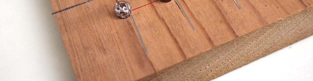
17 Building a Row 17

18 Adding Next Row 18

19 Final Array 19
20 Cube is a Little More Complex But actually is it not much worse Start with the LED plane and build 4, 4x4 planes Each plane would be straight forward to make Now the question is how to connect them together? 20
21 Currently You Have This 4, 4x4 planes top 2nd Would like to create an 8x8 array Create 2, 4x8 arrays by connecting the anodes of 1 st & 2 nd planes together and the 3 rd and 4 th anodes together bottom 3rd 21
22 Connecting Anodes of Planes To connect the 4 anode wires of the two planes On the top plane bend the 4 LED + leads on the left down But leave a little room to bypass the LED On the 2 nd plane, bend the 4 LED + leads on the left up But leave a little room to bypass the LED and miss the wire Solder these 4 wires to each other Your two planes will be floppy Solder two wires on the left, for mechanical support 22

23 Place 1 st Plane in Pliers to Hold 23

24 Add 2 nd Plane 24

25 2 Plane Module 25
26 Now You Have This top 2nd 2, 4x8 planes that are folded around the y axis Create an 8x8 array by connecting the wires of 1 st & 2 nd planes to the wires of the 4 th and 3 rd planes bottom 3rd 26
27 Final Cube top 2nd bottom 3rd 27
28 Completed Cube 28
29 By the End of Lecture, You Should Be Able To: Use LEDs in simple circuits Use time division multiplexing to control LEDs Control n 2 lights using only 2n wires By turning n lights on in n different time slices Create a 2-D plane of LEDs that can be multiplexed And be able to stack planes to create a cube 29
30 LED Cube Driver 30
31 So We Soldered Our Cube We have an 8 x 8 array Logically looks like: Physically it is different Need to drive it To light up the lights For independent light control Either only one + wire high Or only one - wire low Max of 8 LEDs on at once 31
32 The LED Driver Current Requirements Look at current requirements - wires drive 8 LEDs; + wires drive 8 LEDs But we decided to drive only + wire high at a time So each - wire can drive only one LED that is on at any time But each + wire can drive 8 LEDs that are on at on time How much current will each LED take? Series resistance is about 100 total 82 from explicit resistor, from pin Voltage drop across this resistance is 2-3V Current is approximately 20-30mA (for green/blue or red) 32
33 Arduino Current Limitations If you read Arduino specs Each pin can drive 40mA Whole chip should drive less than 200mA Pin current is limited by MOS devices on the chip Have measured 20 ohm If you measure the current it is less ~60mA This makes sense. If the spec is 40mA That is the guaranteed value. Nominally it will be higher 33

34 Max Chip Current Why is there a max total chip current? When current flows out of pin It must flow in from somewhere i = 0 Somewhere is the Gnd pin Or Vdd The current must flow through some small wires Called bonding wires, which connect chip to package Too much current and these wires become fuses Poof, and it is gone Very conservatively spec d. Probably 400mA is ok But remember Poof is possible and permanent 34
35 How to Drive Your LEDs Arduino can drive the - wires directly Use 82 series resistor to limit current Current will be 20mA for blue/green LEDs, 30mA for red Total Arduino current will be around 240mA max Above spec, but will be ok + wire driver will need to supply mA Arduino can t drive that current Will need an external driver for that What type or driver do we need? 35
36 Driving the + Wires of the Cube Want to build as little as possible Need to build 8 of them What do we need? Need to connect to Vdd Need to disconnect from Vdd Don t need to drive it to Gnd 36
37 Where To Put The Resistor and Transistor? 37
M. Horowitz E40M Lecture 13
 http://applecorp.avature.net/ursite? projectid=7260&source=ur+site+ Portal&tags=stanford%7Cfall_2017 %7Cstanford_university_fall_2017_ careers_in_hardware_and_silicon_ panel%7crsvp 1 Lecture 13 Driving
E40M LEDs, Time Multiplexing. M. Horowitz, J. Plummer, R. Howe 1
 E40M LEDs, Time Multiplexing M. Horowitz, J. Plummer, R. Howe 1 Reading Course Reader 2.6 LEDs Course Reader 5.8 - Multiplexing LEDs https://learn.adafruit.com/all-about-leds http://dangerousprototypes.com/docs/
E40M LEDs, Time Multiplexing. M. Horowitz, J. Plummer, R. Howe 1
 E40M LEDs, Time Multiplexing M. Horowitz, J. Plummer, R. Howe 1 Reading Course Reader 2.6 LEDs Course Reader 5.8 - Multiplexing LEDs https://learn.adafruit.com/all-about-leds http://dangerousprototypes.com/docs/
E40M Useless Box, Boolean Logic. M. Horowitz, J. Plummer, R. Howe 1
 E40M Useless Box, Boolean Logic M. Horowitz, J. Plummer, R. Howe 1 Useless Box Lab Project #2 Motor Battery pack Two switches The one you switch A limit switch The first version of the box you will build
Physics 120/220 Lab Equipment, Hints & Tips
 Physics 120/220 Lab Equipment, Hints & Tips Solderless Breadboard... 2 Power supply... 4 Multimeters... 5 Function generator... 5 Oscilloscope... 6 10X probe... 7 Resistor color code... 7 Components...
Connecting LEDs to the ADB I/O
 Application Note AN-2 By Magnus Pettersson September 26 1996 Connecting LEDs to the I/O Introduction The following notes are for those of you who are a bit inexperienced with hardware components. This
E40M. An Introduction to Making: What is EE?
 E40M An Introduction to Making: What is EE? Jim Plummer Stanford University plummer@stanford.edu Chuan-Zheng Lee Stanford University czlee@stanford.edu Roger Howe Stanford University rthowe@stanford.edu
E40M. Binary Numbers, Codes. M. Horowitz, J. Plummer, R. Howe 1
 E40M Binary Numbers, Codes M. Horowitz, J. Plummer, R. Howe 1 Reading Chapter 5 in the reader A&L 5.6 M. Horowitz, J. Plummer, R. Howe 2 Useless Box Lab Project #2 Adding a computer to the Useless Box
E40M Useless Box, Boolean Logic. M. Horowitz, J. Plummer, R. Howe 1
 E40M Useless Box, Boolean Logic M. Horowitz, J. Plummer, R. Howe 1 Useless Box Lab Project #2a Motor Battery pack Two switches The one you switch A limit switch The first version of the box you will build
1/Build a Mintronics: MintDuino
 1/Build a Mintronics: The is perfect for anyone interested in learning (or teaching) the fundamentals of how micro controllers work. It will have you building your own micro controller from scratch on
Vout R LED2 LED1 Nr. of LEDs R Ohm Current ma Vout V Ardunio Pin9
 Tutorial AR Drone Miru Mod on Windows 7 with DX6i, Part 5 V. UFO Doctor, Aug th, 0 7. VLBA experiments with external LED at Arduino Pin9 Introduction Miru Mod 008 offered us the Visible Low Battery Alert
PIC Dev 14 Through hole PCB Assembly and Test Lab 1
 Name Lab Day Lab Time PIC Dev 14 Through hole PCB Assembly and Test Lab 1 Introduction: The Pic Dev 14 is a simple 8-bit Microchip Pic microcontroller breakout board for learning and experimenting with
Discharge by touching: BNC coax shield, outlet metal cover plate, wire connected to GND
 Step-down transformer Very High Voltage Very Low Current Lower Voltage, 110V Power Station Grounding contact (3rd wire) Faulty wiring makes box hot!! Current path splits: 1) to ground (mostly) 2) through
Which LED(s) turn on? May 12, 2017 ENGR 40M Spring 2017 C.Z. Lee, J. Plummer, R. Howe 1
 turn on? May 12, 2017 ENGR 40M Spring 2017 C.Z. Lee, J. Plummer, R. Howe 1") Which LED(s) turn on? May 12, 2017 ENGR 40M Spring 2017 C.Z. Lee, J. Plummer, R. Howe 1 Lab 3b Programming the LED cube ENGR 40M Chuan-Zheng Lee Stanford University 12 May 2017 Overview Goal: To write
Which LED(s) turn on? May 12, 2017 ENGR 40M Spring 2017 C.Z. Lee, J. Plummer, R. Howe 1 Lab 3b Programming the LED cube ENGR 40M Chuan-Zheng Lee Stanford University 12 May 2017 Overview Goal: To write
LED Knight Rider. Yanbu College of Applied Technology. Project Description
 LED Knight Rider Yanbu College of Applied Technology Project Description This simple circuit functions as a 12 LED chaser. A single illuminated LED 'walks' left and right in a repeating sequence, similar
PIC Dev 14 Surface Mount PCB Assembly and Test Lab 1
 Name Lab Day Lab Time PIC Dev 14 Surface Mount PCB Assembly and Test Lab 1 Introduction: The Pic Dev 14 SMD is a simple 8-bit Microchip Pic microcontroller breakout board for learning and experimenting
Analog Input. Sure sure, but how to make a varying voltage? With a potentiometer. Or just pot.
 Analog Input Sure sure, but how to make a varying voltage? With a potentiometer. Or just pot. +5V measure gnd Color coding: red goes to power, blue to ground, purple to measure here (it s a mix, see?)
K8099 NIXIE CLOCK. * optional enclosure TKOK19 (black) - TKOK17 (white) ** optional plexiglass enlcosure B8099 ILLUSTRATED ASSEMBLY MANUAL
 - TKOK17 (white) ** optional plexiglass enlcosure B8099 ILLUSTRATED ASSEMBLY MANUAL") Total solder points: 230 + 74 Difficulty level: beginner 1 2 3 4 5 advanced NIXIE CLOCK K8099 ** * A unique combination of both vintage and modern electronics ILLUSTRATED ASSEMBLY MANUAL H8099IP-1 * optional
Total solder points: 230 + 74 Difficulty level: beginner 1 2 3 4 5 advanced NIXIE CLOCK K8099 ** * A unique combination of both vintage and modern electronics ILLUSTRATED ASSEMBLY MANUAL H8099IP-1 * optional
Digital Electronics & Computer Engineering (E85)
") Digital Electronics & Computer Engineering (E85) Lab 4: Thunderbird Turn Signal Introduction In this lab, you will design a finite state machine to control the taillights of a 1965 Ford Thunderbird 1 and
Digital Electronics & Computer Engineering (E85) Lab 4: Thunderbird Turn Signal Introduction In this lab, you will design a finite state machine to control the taillights of a 1965 Ford Thunderbird 1 and
Which LED(s) turn on? May 4, 2018 E40M Spring 2018 T. Diamandis, J. Plummer, R. Howe, C. Z. Lee 1
 turn on? May 4, 2018 E40M Spring 2018 T. Diamandis, J. Plummer, R. Howe, C. Z. Lee 1") Which LED(s) turn on? May 4, 2018 E40M Spring 2018 T. Diamandis, J. Plummer, R. Howe, C. Z. Lee 1 Lab 3b, 3c The LED Cube ENGR 40M Theo Diamandis Stanford University 04 May 2018 Overview Goal: To write
Which LED(s) turn on? May 4, 2018 E40M Spring 2018 T. Diamandis, J. Plummer, R. Howe, C. Z. Lee 1 Lab 3b, 3c The LED Cube ENGR 40M Theo Diamandis Stanford University 04 May 2018 Overview Goal: To write
Part 2: Building the Controller Board
 v3.01, June 2018 1 Part 2: Building the Controller Board Congratulations for making it this far! The controller board uses smaller components than the wing boards, which believe it or not, means that everything
dual bipolar voltage controlled step sequencer DIY ASSEMBLY MANUAL v1.03
 dual bipolar voltage controlled step sequencer DIY ASSEMBLY MANUAL v1.03 Contents Contents... 2 Introduction... 3 Part Sourcing Notes for Non Kit Builders... 3 Eurorack Kit Assembly... 4 Resistors and
Lab 0: Wire Wrapping Project: Counter Board
 Lab 0: Wire Wrapping Project: Counter Board September 3, 2008 In this experiment, you will build a simple counter circuit that can be plugged into your breadboard. It will provide a set of TTL output signals
Introduction to CMOS VLSI Design (E158) Lecture 7: Synthesis and Floorplanning
 Lecture 7: Synthesis and Floorplanning") Harris Introduction to CMOS VLSI Design (E158) Lecture 7: Synthesis and Floorplanning David Harris Harvey Mudd College David_Harris@hmc.edu Based on EE271 developed by Mark Horowitz, Stanford University
Harris Introduction to CMOS VLSI Design (E158) Lecture 7: Synthesis and Floorplanning David Harris Harvey Mudd College David_Harris@hmc.edu Based on EE271 developed by Mark Horowitz, Stanford University
Test Procedure: Fault Finding Circuits
 Test Procedure: Fault Finding Circuits 1 Test Procedure: Fault Finding Circuits Known as TROUBLE SHOOTING in USA and Far East 2 BEFORE STARTING SAFETY TEST EQUIPMENT DOCUMENTATION 3 BEFORE STARTING SAFETY
Thumb Joystick Retail. Tools and parts you'll need. Things you'll want to know. How does it work? Skill Level: Beginner. by MikeGrusin March 22, 2011
 Thumb Joystick Retail Skill Level: Beginner by MikeGrusin March 22, 2011 Thank you for purchasing our Thumb Joystick! Whether you're blasting aliens or driving a robot, you'll find it a very useful addition
Universal Keying Adapter 3+
 Universal Keying Adapter 3+ The Universal Keying Adapter Version 3+ kit will allow you to key nearly any transmitter or transceiver with a straight key, electronic keyer, computer serial or parallel port
DIY Kit 113. DUAL STEPPER MOTOR CONTROLLER
 INTRODUCTION This kit enables users to control two unipolar stepper motors via a parallel/printer port of a PC. Four digital inputs are also included. These can be used for monitoring external switches
How-To: Make an RGB combination door lock (Part 1)
") How-To: Make an RGB combination door lock (Part 1) Written By: Feitan 2017 www.botsbits.org Page 1 of 14 INTRODUCTION Part 2 can be found here 2017 www.botsbits.org Page 2 of 14 Step 1 How-To: Make an
How-To: Make an RGB combination door lock (Part 1) Written By: Feitan 2017 www.botsbits.org Page 1 of 14 INTRODUCTION Part 2 can be found here 2017 www.botsbits.org Page 2 of 14 Step 1 How-To: Make an
Necessary software and hardware:
 Necessary software and hardware: Bases: First, remember that I m a French guy so my English is not perfect ;) If you see any mistakes, don t hesitate to tell me so I can correct them (my email is at the
USB PowerControl 0042-USBPC-DSBT / USBPCNE-DSBT
 Features and Benefits:! The board is a USB to USB solid state relay. It comes in two flavors, one with an Active High Enable line and the other with an Active Low Enable line. The software for this device
Halloween Pumpkinusing. Wednesday, October 17, 12
 Halloween Pumpkinusing Blink LED 1 What you will need: 1 MSP-EXP430G2 1 3 x 2 Breadboard 3 560 Ohm Resistors 3 LED s (in Red Color Range) 3 Male to female jumper wires 1 Double AA BatteryPack 2 AA Batteries
Cygnos360 V2 Installation Manual
 VERSION 1.0. - OKTOBER, 2009 www.cygnos360.com Contents: 1. What you need...2 1.1. Tools...2 2. Preparation...3 2.1. Preparing the solder points...3 3. Installing in your Xbox360...4 3.1. Installing the
Building the FlipChip Tester
 Building the FlipChip Tester 1. Assembly of the Core Board You will need a fine low-wattage soldering iron and a Voltmeter. Take your time to solder the components on the Core Board. Better to spend a
Electronics Construction Manual
 Electronics Construction Manual MitchElectronics 2018 Version 1 07/05/2018 www.mitchelectronics.co.uk CONTENTS Introduction 3 How To Solder 4 Resistors 5 Capacitors 6 Diodes and LEDs 7 Switches 8 Transistors
Which LED(s) turn on?
 turn on?") Go to www.menti.com and use the code 90 95 79 Which LED(s) turn on? May 4, 2018 E40M Spring 2018 T. Diamandis, J. Plummer, R. Howe, C. Z. Lee 1 Lab 3b, 3c The LED Cube ENGR 40M Theo Diamandis Stanford
Go to www.menti.com and use the code 90 95 79 Which LED(s) turn on? May 4, 2018 E40M Spring 2018 T. Diamandis, J. Plummer, R. Howe, C. Z. Lee 1 Lab 3b, 3c The LED Cube ENGR 40M Theo Diamandis Stanford
Arduino 05: Digital I/O. Jeffrey A. Meunier University of Connecticut
 Arduino 05: Digital I/O Jeffrey A. Meunier jeffm@engr.uconn.edu University of Connecticut About: How to use this document I designed this tutorial to be tall and narrow so that you can read it on one side
ArdPicProg. Arduino PIC Programmer Construction Manual. Version 1.2 Release date 03/2015. Gregor Schlechtriem
 ArdPicProg Arduino PIC Programmer Construction Manual Version 1.2 Release date 03/2015 Gregor Schlechtriem webmaster@pikoder.de www.pikoder.de Table of Contents Helpful Hints 3 Contents of the Kit and
Module 3B: Arduino as Power Supply
 Name/NetID: Teammate/NetID: Module 3B: Laboratory Outline As you work on through the labs during the semester and some of the modules you may want to continue experimenting at home. Luckily the microprocessor
Manual Version March 2007
 Manual Version 1.1 - March 2007 Page 1 Table of Contents Section1: 6922 Line Board Build... 3 6922 Line Board Version Notes... 5 6922 Line Board Build - HARD-WIRED VERSION... 5 Final Connections and Checks
K191 3 Channel RGB LED Controller
 K191 3 Channel RGB LED Controller 1 Introduction. This kit has been designed to function as a versatile LED control module. The LED controller provides 3 high current channels to create light effects for
9 Output Devices: Buzzers
 9 Output Devices: Buzzers Project In this project, you will learn how to connect and control LEDs (Light Emitting Diode) and a buzzer with the Raspberry Pi. Components In addition to your Raspberry Pi,
DSI-4. DMX Optically Isolated 1x4 Splitter. D Series. DSI_4 Users Manual r3.lwp copyright 2009, 2010, 2011 ELM V. T. Inc.
 DSI-4 DMX Optically Isolated 1x4 Splitter D Series 1 Table Of Contents IMPORTANT SAFEGUARDS... DSI-4 OVERVIEW... CONNECTION... PCB BLOCK DIAGRAM... SERVICING... TROUBLESHOOTING... SPECIFICATIONS... 2 3
Adobe Flash CS3 Reference Flash CS3 Application Window
 Adobe Flash CS3 Reference Flash CS3 Application Window When you load up Flash CS3 and choose to create a new Flash document, the application window should look something like the screenshot below. Layers
The GENIE Light Kit is ideal for introducing simple lighting projects, such as an electronic die, a wearable badge or a night-time warning system.
 Introduction 1 Welcome to the GENIE microcontroller system! The GENIE Light Kit is ideal for introducing simple lighting projects, such as an electronic die, a wearable badge or a night-time warning system.
Lab 2.2 Ohm s Law and Introduction to Arduinos
 Lab 2.2 Ohm s Law and Introduction to Arduinos Objectives: Get experience using an Arduino Learn to use a multimeter to measure Potential units of volts (V) Current units of amps (A) Resistance units of
Objectives: Learn how to input and output analogue values Be able to see what the Arduino is thinking by sending numbers to the screen
 Objectives: Learn how to input and output analogue values Be able to see what the Arduino is thinking by sending numbers to the screen By the end of this session: You will know how to write a program to
AUDIO AMPLIFIER PROJECT
 Intro to Electronics 110 - Audio Amplifier Project AUDIO AMPLIFIER PROJECT In this project, you will learn how to master a device by studying all the parts and building it with a partner. Our test subject:
Cube67 - Modular I/O station
 Compact modules Cube67 DI16 C 8xM12 Cube67 DI8 C 4xM12 Cube67 DI8 C 8xM8 Digital inputs Art.-No. UL 56602 UL 56612 UL 56622 approx. 50 ma approx. ma Terminator integrated Configuration PIN 2 input/diagnostic
MEGATRONICS V3.0 QUICK START GUIDE
 MEGATRONICS V3.0 QUICK START GUIDE Thank you for purchasing the Megatronics v3.0! This small guide will answer the basic questions on how to connect the board to your 3D printer. For more information visit
Display Datasheet. 3.1", 105 ppi, 312x74 pixels
 Display Datasheet 3.1", 105 ppi, 312x74 pixels Part-No. 700524 Revision 1 PL-AE-DDS-002798 All rights reserved. Revision 1 Display Datasheet 700524 3.1 1.docx Page 1 of 14 Revision Status 1 Date Author
Lecture 8: Synthesis, Implementation Constraints and High-Level Planning
 Lecture 8: Synthesis, Implementation Constraints and High-Level Planning MAH, AEN EE271 Lecture 8 1 Overview Reading Synopsys Verilog Guide WE 6.3.5-6.3.6 (gate array, standard cells) Introduction We have
Proto-DB (#28310): Prototyping Daughterboard
: Prototyping Daughterboard") Web Site: www.parallax.com Forums: forums.parallax.com Sales: sales@parallax.com Technical: support@parallax.com Office: (916) 624-8333 Fax: (916) 624-8003 Sales: (888) 512-1024 Tech Support: (888) 997-8267
Web Site: www.parallax.com Forums: forums.parallax.com Sales: sales@parallax.com Technical: support@parallax.com Office: (916) 624-8333 Fax: (916) 624-8003 Sales: (888) 512-1024 Tech Support: (888) 997-8267
Bill of Materials: 8x8 LED Matrix Driver Game PART NO
 8x8 LED Matrix Driver Game PART NO. 2171031 This Game Maker II kit is a game design platform using a single color 8x8 matrix LED without the need for a shift register or expensive Arduino. The kit includes
CHAPTER 5. Voltage Regulator
 CHAPTER 5 Voltage Regulator In your robot, the energy is derived from batteries. Specifically, there are two sets of batteries wired up to act as voltage sources; a 9V battery, and two 1.5V batteries in
CS12020 (Computer Graphics, Vision and Games) Worksheet 1
 Worksheet 1") CS12020 (Computer Graphics, Vision and Games) Worksheet 1 Jim Finnis (jcf1@aber.ac.uk) 1 Getting to know your shield First, book out your shield. This might take a little time, so be patient. Make sure
CS12020 (Computer Graphics, Vision and Games) Worksheet 1 Jim Finnis (jcf1@aber.ac.uk) 1 Getting to know your shield First, book out your shield. This might take a little time, so be patient. Make sure
MCU-9201MT22 venetian blind controller
 MCU-9201MT22 venetian blind controller It is strongly recommended to read and follow the instructions in this manual carefully, before you start installing or programming a system. Installation, configuration
PANDORA HACKER GUIDE
 PANDORA HACKER GUIDE WARNING: Modifying your PCB is not covered by your warranty and any damage caused as a result will be the sole responsibility of the owner to fix or to have fixed at a fee set by the
EK307 Lab: Microcontrollers
 EK307 Lab: Microcontrollers Laboratory Goal: Program a microcontroller to perform a variety of digital tasks. Learning Objectives: Learn how to program and use the Atmega 323 microcontroller Suggested
RC Tractor Guy Controller V2.1 Assembly Guide
 RC Tractor Guy Controller V. Assembly Guide Features 0 Push button inputs Dual axis thumb sticks with built-in push button Rotary encoders with built-in push button MCU Socket to suit Meduino Mega 560
Installation/assembly manual for DCC/Power shield
 Installation/assembly manual for DCC/Power shield The DCC circuit consists of the following components: R1/R6 R2/R3 R4/R5 D1 C2 2 kω resistor ½ Watt (colour code Red/Black/Black/Brown/Brown) 10 kω resistor
Wiring Instructions v3
 Wiring Instructions v3 Gatekeeper h4.1 Technical Support support@gymmastersoftware.com USA: 415 678 1270 Australia: 03 9111 0323 : 03 974 9169 Copyright 2017 Treshna Enterprises. All rights reserved. Table
Zero2Go. User Manual (revision 1.03) Wide Input Range Power Supply for Your Raspberry Pi. Copyright 2017 UUGear s.r.o. All rights reserved.
 Wide Input Range Power Supply for Your Raspberry Pi. Copyright 2017 UUGear s.r.o. All rights reserved.") Zero2Go Wide Input Range Power Supply for Your Raspberry Pi User Manual (revision 1.03) Copyright 2017 UUGear s.r.o. All rights reserved. Table of Content Product Overview... 1 Product Details... 3 Package
Zero2Go Wide Input Range Power Supply for Your Raspberry Pi User Manual (revision 1.03) Copyright 2017 UUGear s.r.o. All rights reserved. Table of Content Product Overview... 1 Product Details... 3 Package
Pacific Antenna Two Tone Generator
 Pacific Antenna Two Tone Generator Description Our Two Tone Generator kit provides two non-harmonic, sine wave signals for testing audio circuits Outputs of approximately 700Hz and 1900Hz and the combination
Button Code Kit. Assembly Instructions and User Guide. Single Button Code Entry System
 Button Code Kit Single Button Code Entry System Assembly Instructions and User Guide Rev 1.0 December 2009 www.alan-parekh.com Copyright 2009 Alan Electronic Projects Inc. 1. Introduction... 4 1.1 Concept
Microcontrollers. Outline. Class 1: Serial and Digital I/O. March 7, Quick Tour of the Board. Pins, Ports, and Their Registers
 Microcontrollers Class 1: Serial and Digital I/O March 7, 2011 Outline Quick Tour of the Board Pins, Ports, and Their Registers Boolean Operations Cylon Eyes Digital Input and Testing Particular Pin States
Using PSpice to Simulate Transmission Lines K. A. Connor Summer 2000 Fields and Waves I
 Using PSpice to Simulate Transmission Lines K. A. Connor Summer 2000 Fields and Waves I We want to produce the image shown above as a screen capture or below as the schematic of this circuit. R1 V1 25
DIGWDF Ren-W Universal Assembly Guide
 DIGWDF Ren-W Universal Assembly Guide Overview Before starting, be sure to read through the entire guide to familiarize yourself with the parts and parts locations. In many cases, you may not need to install
10/24/2016. Let s Name Some Groups of Bits. ECE 120: Introduction to Computing. We Just Need a Few More. You Want to Use What as Names?!
 University of Illinois at Urbana-Champaign Dept. of Electrical and Computer Engineering ECE 120: Introduction to Computing Memory Let s Name Some Groups of Bits I need your help. The computer we re going
Display Datasheet. 2.1", 132 ppi, 240x146 pixels
 Display Datasheet 2.1", 132 ppi, 240x146 pixels Part-No. 700756 Revision 1 Display Datasheet 700756 2.1 1.docx Page 1 of 12 Revision Status Date Author Reason of Modification 1 15-Jan-2018 RN Initial version
Images Scientific OWI Robotic Arm Interface Kit (PC serial) Article
 Article") Images Scientific OWI Robotic Arm Interface Kit (PC serial) Article Images Company Robotic Arm PC Interface allows real time computer control and an interactive script writer/player for programming and
Images Scientific OWI Robotic Arm Interface Kit (PC serial) Article Images Company Robotic Arm PC Interface allows real time computer control and an interactive script writer/player for programming and
Layad Circuits Arduino Basic Kit B. Content Summary
 Layad Circuits This kit is a careful selection of sensors, displays, modules, an Arduino Uno, connectors and other essential parts meant to facilitate learning of the hardware and software components of
E85: Digital Design and Computer Engineering Lab 1: Electrical Characteristics of Logic Gates
 E85: Digital Design and Computer Engineering Lab 1: Electrical Characteristics of Logic Gates Objective The purpose of this lab is to become comfortable with logic gates as physical objects, to interpret
VKey Voltage Keypad Hookup Guide
 Page 1 of 8 VKey Voltage Keypad Hookup Guide Introduction If you need to add a keypad to your microcontroller project, but don t want to use up a lot of I/O pins to interface with it, the VKey is the solution
Electronics Construction Manual
 Electronics Construction Manual MitchElectronics 2019 Version 3 04/02/2019 www.mitchelectronics.co.uk CONTENTS Introduction 3 How To Solder 4 Resistors 5 Capacitors 6 Diodes and LEDs 7 Switches 8 Transistors
Embedded Systems and Software
 Embedded Systems and Software Lecture 12 Some Hardware Considerations Hardware Considerations Slide 1 Logic States Digital signals may be in one of three states State 1: High, or 1. Using positive logic
Laboratory of Sensors Engineering Sciences 9 CFU
 Laboratory of Sensors Engineering Sciences 9 CFU Contacts Alexandro Catini catini@ing.uniroma2.it Phone: +39 06 7259 7347 Department of Electronic Engineering First Floor - Room B1-07b Course Outline THEORY
Outline for Today. Lab Equipment & Procedures. Teaching Assistants. Announcements
 Announcements Homework #2 (due before class) submit file on LMS. Submit a soft copy using LMS, everybody individually. Log onto the course LMS site Online Assignments Homework 2 Upload your corrected HW2-vn.c
EE115C Digital Electronic Circuits. Tutorial 4: Schematic-driven Layout (Virtuoso XL)
") EE115C Digital Electronic Circuits Tutorial 4: Schematic-driven Layout (Virtuoso XL) This tutorial will demonstrate schematic-driven layout on the example of a 2-input NAND gate. Simple Layout (that won
EE115C Digital Electronic Circuits Tutorial 4: Schematic-driven Layout (Virtuoso XL) This tutorial will demonstrate schematic-driven layout on the example of a 2-input NAND gate. Simple Layout (that won
Build Your Own Home Security System
 Build Your Own Home Security System Student Lab Guide Engineering Teaching Laboratory Name Date Lab Partner(s) NEW TERMS Electric Circuit: Electric circuits are paths for transmitting electric current,
GSV-1A4 M12/2 M12/2. Highlights
 GSV-1A4 M12/2 M12/2 Highlights Input sensitivity: 2mV/V; 4mV/V, 2 mv/v, 1mV/V, 0.5mV/V configurable via jumpers Output signals ±10V AND 12mA+-8mA on 15 pin Sub-D Integrated half and quarter bridge completion
University of Hull Department of Computer Science C4DI Interfacing with Arduinos
 Introduction Welcome to our Arduino hardware sessions. University of Hull Department of Computer Science C4DI Interfacing with Arduinos Vsn. 1.0 Rob Miles 2014 Please follow the instructions carefully.
Network Controller. Installation/Troubleshooting Instructions NK220 COM1131C
 Network Controller NK220 COM1131C Installation/Troubleshooting Instructions Part No. 70399101R4 October 2009 Table of Contents Getting Started... 2 Components of Network Controller... 2 System Overview...
4x4x4 LED Cube Kit with Arduino
 4x4x4 LED Cube Kit with Arduino 1. Introduction For ARDUINO starters, we d love to do projects that would blow people s mind off. But without certain basic knowledge of electronics, we may find it difficult
Introduction to MATLABs Data Acquisition Toolbox, the USB DAQ, and accelerometers
 Introduction to MATLABs Data Acquisition Toolbox, the USB DAQ, and accelerometers This week we will start to learn the software that we will use through the course, MATLAB s Data Acquisition Toolbox. This
Revision No. Date Description Item Page
 Midas Components Limited Electra House 32 Southtown Road Great Yarmouth Norfolk NR31 0DU England Telephone +44 (0)1493 602602 Fax +44 (0)1493 665111 Email sales@midasdisplays.com Website www.midasdisplays.com
Propeller Project Board USB (#32810)
") Web Site: www.parallax.com Forums: forums.parallax.com Sales: sales@parallax.com Technical: support@parallax.com Office: (916) 624-8333 Fax: (916) 624-8003 Sales: (888) 512-1024 Tech Support: (888) 997-8267
Web Site: www.parallax.com Forums: forums.parallax.com Sales: sales@parallax.com Technical: support@parallax.com Office: (916) 624-8333 Fax: (916) 624-8003 Sales: (888) 512-1024 Tech Support: (888) 997-8267
EFL VI TESTER - TFT MANUEL BOOK
 www.reelektronik.com EFL VI TESTER - TFT MANUEL BOOK (FAULT LOCATOR WITH IMPEDANCE (VI) CURVES TECHNIQUE) NOTES ; 1) Disconnecting the power to discharge the capacitor in the abdomen and tested electronic
ARDUINO UNO REV3 Code: A000066
 ARDUINO UNO REV3 Code: A000066 The UNO is the best board to get started with electronics and coding. If this is your first experience tinkering with the platform, the UNO is the most robust board you can
NAME EET 2259 Lab 3 The Boolean Data Type
 NAME EET 2259 Lab 3 The Boolean Data Type OBJECTIVES - Understand the differences between numeric data and Boolean data. -Write programs using LabVIEW s Boolean controls and indicators, Boolean constants,
XYLOPHONE KIT ESSENTIAL INFORMATION. Version 2.0 CREATE YOUR OWN ELECTRONIC MUSICAL INTRUMENT WITH THIS
 ESSENTIAL INFORMATION BUILD INSTRUCTIONS CHECKING YOUR PCB & FAULT-FINDING MECHANICAL DETAILS HOW THE KIT WORKS CREATE YOUR OWN ELECTRONIC MUSICAL INTRUMENT WITH THIS XYLOPHONE KIT Version 2.0 Build Instructions
The PUMPKIN LIGHT LED
 The PUMPKIN LIGHT LED PUMPKIN LIGHT LED By Mark McCuller Email: mcculler@mail.com DESIGN SUMMARY The PUMPKIN LIGHT LED By: Mark McCuller The Pumpkin Light LED is a battery-powered device that illuminates
HUB-ee BMD-S Arduino Proto Shield V1.1
 HUB-ee BMD-S Arduino Proto Shield V1.1 User guide and assembly instructions Document Version 0.5 Introduction & Board Guide 2 Schematic 3 Quick User Guide 4 Assembly Guide 6 Kit Contents 7 1) Diodes and
Introduction to PSpice
 Introduction to PSpice Simulation Software 1 The Origins of SPICE In the 1960 s, simulation software begins CANCER Computer Analysis of Nonlinear Circuits, Excluding Radiation Developed at the University
Schematic Diagram: R2,R3,R4,R7 are ¼ Watt; R5,R6 are 220 Ohm ½ Watt (or two 470 Ohm ¼ Watt in parallel)
") Nano DDS VFO Rev_2 Assembly Manual Farrukh Zia, K2ZIA, 2016_0130 Featured in ARRL QST March 2016 Issue Nano DDS VFO is a modification of the original VFO design in Arduino Projects for Amateur Radio by
Nano DDS VFO Rev_2 Assembly Manual Farrukh Zia, K2ZIA, 2016_0130 Featured in ARRL QST March 2016 Issue Nano DDS VFO is a modification of the original VFO design in Arduino Projects for Amateur Radio by
Assembling the Printed Circuit Board for the EDE1200 Robot
 This board receives instructions from either a CBL2, a LabPro or (with an adapter cable) an original CBL. The board has two 595 shift registers (each providing 8 bits of on-board memory) and two EDE1200
Troubleshooting a K40 Laser Power Subsystem
 Troubleshooting a K40 Laser Power Subsystem This work is licensed under a Creative Commons Attribution-onCommercial 4.0 International License. The author(s) do not make any warranties about the completeness,
DEV-1 HamStack Development Board
 Sierra Radio Systems DEV-1 HamStack Development Board Reference Manual Version 1.0 Contents Introduction Hardware Compiler overview Program structure Code examples Sample projects For more information,
AXE Stack 18. BASIC-Programmable Microcontroller Kit. An inexpensive introduction to microcontroller technology for all ability levels
 Ltd AXE Stack 18 BASIC-Programmable Microcontroller Kit a division of An inexpensive introduction to microcontroller technology for all ability levels Free Windows interface software Programmable in BASIC
Building your own special-purpose embedded system gadget.
 Bare-duino Building your own special-purpose embedded system gadget. Saves a little money. You can configure the hardware exactly the way that you want. Plus, it s fun! bare-duino 1 Arduino Uno reset I/O