Chapter 2: Configure a Network Operating System. Every computer requires an operating system to function, including computerbased
|
|
|
- Clinton Henderson
- 6 years ago
- Views:
Transcription

1 Chapter 2: Configure a Network Operating System Every computer requires an operating system to function, including computerbased network devices such as switches, routers, access points, and firewalls. These network devices use an operating system called a network operating system.

2 Class Activity - It Is Just an Operating System

3 Operating Systems All end devices and network devices require an operating system (OS). As shown in Figure 1, the portion of the OS that interacts directly with computer hardware is known as the kernel. The portion that interfaces with applications and the user is known as the shell. The user can interact with the shell using a command-line interface (CLI) or a graphical user interface (GUI).

4 Purpose of OS Network operating systems are similar to a PC operating system. Through a GUI, a PC operating system enables a user to: Use a mouse to make selections and run programs Enter text and text-based commands View output on a monitor A CLI-based network operating system like the Cisco IOS on a switch or router enables a network technician to: Use a keyboard to run CLI-based network programs Use a keyboard to enter text and textbased commands View output on a monitor
5 Access Methods

6 Terminal Emulation Programs There are a number of excellent terminal emulation programs available for connecting to a networking device either by a serial connection over a console port or by a SSH/Telnet connection. Some of these include: PuTTY Tera Term SecureCRT OS X Terminal

7 Activity - Accessing Devices
8 Cisco IOS Modes of Operation Click Play in the figure to view a video demonstration of how to establish a console connection with a switch.

9 Primary Command Modes
10 Configuration Command Modes

11 Navigate Between IOS Modes Various commands are used to move in and out of command prompts. To move from user EXEC mode to privileged EXEC mode, use the enable command. Use the disable privileged EXEC mode command to return to user EXEC mode.

12 Basic IOS Command Structure A Cisco IOS device supports many commands. Each IOS command has a specific format or syntax and can only be executed in the appropriate mode. The general syntax for a command is the command followed by any appropriate keywords and arguments.

13 IOS Command Syntax The following examples demonstrate conventions used to document and use IOS commands. ping ip-address - The command is ping and the user-defined argument is the ip-address of the destination device. For example, ping traceroute ip-address - The command is traceroute and the user-defined argument is the ipaddress of the destination device. For example, traceroute
14 IOS Help Features To access context-sensitive help, simply enter a question mark,?, at the CLI.

15 Hotkeys and Shortcuts
16 Video Demonstration Hotkeys and Shortcuts
17 Packet Tracer - Navigating the IOS

18 Lab - Establishing a Console Session with Tera Term In this lab, you will complete the following objectives: Part 1: Access a Cisco Switch through the Serial Console Port Part 2: Display and Configure Basic Device Settings Part 3: (Optional) Access a Cisco Router Using a Mini-USB Console Cable

19 Device Names

20 Configure Hostnames


21 Secure Device Access

22 Configure Passwords

23 Encrypt Passwords
24 Banner Messages


25 Syntax Checker - Limiting Access to a Switch

26 Save the Running Configuration File

27 Alter the Running Configuration

28 Capture Configuration to a Text File
29 Packet Tracer - Configuring Initial Switch Settings

30 IP Addresses

31 Interfaces and Ports


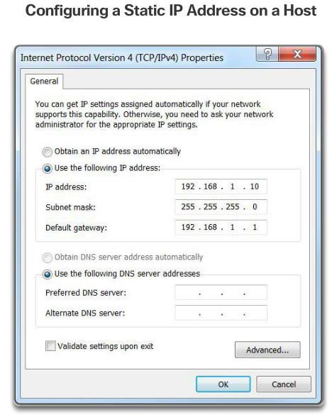
32 Manual IP Address Configuration for End Devices


33 Automatic IP Address Configuration for End Devices
34 Switch Virtual Interface Configuration

35 Syntax Checker - Configuring a Switch Virtual Interface

36 Packet Tracer - Implementing Basic Connectivity
37 Interface Addressing Verification

38 End-to-End Connectivity Test The ping command can be used to test connectivity to another device on the network or a website on the Internet.
 Part 2: Configure PC Hosts Part 3: Configure and Verify Basic Switch")
39 Lab - Building a Simple Network In this lab, you will complete the following objectives: Part 1: Set Up the Network Topology (Ethernet only) Part 2: Configure PC Hosts Part 3: Configure and Verify Basic Switch Settings

40 Lab - Configuring a Switch Management Address In this lab, you will complete the following objectives: Part 1: Configure a Basic Network Device Part 2: Verify and Test Network Connectivity

41 Class Activity - Tutor Me

42 Packet Tracer - Skills Integration Challenge

43 Chapter 2: Configure a Network Operating System
44
45
CHAPTER 2 ACTIVITY
 CHAPTER 2 ACTIVITY 2.1.1.1 1. CLI stands for 2. GUI stands for 3. Write the step you used to go to CLI interface on Windows 4. The OS, normally loads from a disk drive, into RAM. 5. The portion of the
CCNA 1 Chapter 2 v5.0 Exam Answers %
 CCNA 1 Chapter 2 v5.0 Exam Answers 2015 100% 1. Which two features are characteristics of flash memory? (Choose two.) Flash provides nonvolatile storage. Flash receives a copy of the IOS from RAM when
CCNA 1 Chapter 2 v5.0 Exam Answers 2013
 CCNA 1 Chapter 2 v5.0 Exam Answers 2013 1. Refer to the exhibit. A switch was configured as shown. A ping to the default gateway was issued, but the ping was not successful. Other switches in the same
Chapter 2. Chapter 2 A. Configuring a Network Operating System
 Chapter 2 Chapter 2 A Configuring a Network Operating System Chapter 2 Cisco IOS IOS stands for Internetwork Operating System It is a family of software used on most Cisco Systems routers and current Cisco
Jaringan Komputer (CCNA-1)
") Jaringan Komputer (CCNA-1) #2 Configuring a Network Operating System Susmini I. Lestariningati, M.T Introduction (1) Home networks typically interconnect a wide variety of end devices including PCs, laptops,
Jaringan Komputer (CCNA-1) #2 Configuring a Network Operating System Susmini I. Lestariningati, M.T Introduction (1) Home networks typically interconnect a wide variety of end devices including PCs, laptops,
MiPDF.COM. 3. Which procedure is used to access a Cisco 2960 switch when performing an initial configuration in a secure environment?
 CCNA1 v6.0 Chapter 2 Exam Answers 2017 (100%) MiPDF.COM 1. What is the function of the kernel of an operating software? It provides a user interface that allows users to request a specific task. The kernel
Configuring and Testing Your Network
 Configuring and Testing Your Network Network Fundamentals Chapter 11 1 Role of Internetwork Operating System (IOS) Identify several classes of devices that have IOS embedded 2 Role of Internetwork Operating
Lab Command Line Fundamentals Instructor Version 2500
 Lab 2.2.9 Command Line Fundamentals Instructor Version 2500 Objective Log into a router and go to the user and privileged modes. Use several basic router commands to determine how the router is configured.
Packet Tracer - Navigating the IOS
 Topology Objectives Part 1: Establish Basic Connections, Access the CLI, and Explore Help Part 2: Explore EXEC Modes Part 3: Set the Clock Background In this activity, you will practice skills necessary
Lab 1.3.2: Review of Concepts from Exploration 1 - Challenge
 Lab 1.3.2: Review of Concepts from Exploration 1 - Challenge Topology Diagram Learning Objectives Upon completion of this lab, you will be able to: Create a logical topology given network requirements
Lab - Examining Telnet and SSH in Wireshark
 Topology Addressing Table Objectives Device Interface IP Address Subnet Mask Default Gateway R1 G0/1 192.168.1.1 255.255.255.0 N/A PC-A NIC 192.168.1.3 255.255.255.0 192.168.1.1 Part 1: Configure the Devices
Retake - Skills Assessment Student Training (Answer Key)
") Retake - Skills Assessment Student Training (Answer Key) Name:. Topology Assessment Objectives Part 1: Develop the IPv4 Address Scheme (15 points, 0 minutes) Part 2: Configure Device IPv4 and Security
Retake - Skills Assessment Student Training (Answer Key) Name:. Topology Assessment Objectives Part 1: Develop the IPv4 Address Scheme (15 points, 0 minutes) Part 2: Configure Device IPv4 and Security
Configuring and Testing Your Network
 Configuring and Testing Your Network Network Fundamentals Chapter 11 Version 4.0 1 Objectives Define the role of the Internetwork Operating System (IOS). Use Cisco CLI commands to perform basic router
Skills Assessment Student Practice
 Skills Assessment Student Practice Topology Assessment Objectives Part 1: Develop the IPv4 Address Scheme (15 points, 20 minutes) Part 2: Initialize and Reload Devices (10 points, 5 minutes) Part 3: Configure
Lab 7 Configuring Basic Router Settings with IOS CLI
 Lab 7 Configuring Basic Router Settings with IOS CLI Objectives Part 1: Set Up the Topology and Initialize Devices Cable equipment to match the network topology. Initialize and restart the router and switch.
IOS and Configuration Basics
 APPENDIX C This appendix contains basic information about the Cisco Internet Operating System (IOS) software and includes the following sections: Cisco IOS Modes of Operation Getting Context-Sensitive
config mode: Router> enable Router# configure terminal Enter configuration commands, one per line. End with CNTL/Z.
 CCNA1-CH2 2.1.1.1 OS / IOS 2.1.2.1 console (serial) / ssh / telnet 2.1.2.2 putty (teraterm / mobxterm / ) 2.1.3.1 IOS operation: console (cable + config) in packettracer 2.1.3.2 user EXEC vs Privileged
King Fahd University of Petroleum & Minerals. Configuration of Routers and Establishing Routed Networks
 King Fahd University of Petroleum & Minerals Electrical Engineering Department EE 400, Experiment # 7 Objectives: Configuration of Routers and Establishing Routed Networks The objective of this experiment
Antonio Cianfrani. Packet Tracer
 Antonio Cianfrani Packet Tracer Packet Tracer (1/2) Packet Tracer? Cisco Packet Tracer is a software able to emulate CISCO networking devices. Packet Tracer features: Allows to create network topologies
Lab Using the CLI to Gather Network Device Information Topology
 Topology Addressing Table Objectives Device Interface IP Address Subnet Mask Default Gateway R1 G0/1 192.168.1.1 255.255.255.0 N/A Lo0 209.165.200.225 255.255.255.224 N/A S1 VLAN 1 192.168.1.11 255.255.255.0
Lab - Building a Switch and Router Network
 Topology Addressing Table Device Interface IP Address Subnet Mask Default Gateway G0/0 192.168.0.1 N/A G0/1 192.168.1.1 N/A PC-A NIC 192.168.1.3 192.168.1.1 PC-B NIC 192.168.0.3 192.168.0.1 R1 Objectives
Skills Assessment Student Training Exam
 Skills Assessment Student Training Exam Time: 20 minutes Given an IP address and mask of (address / mask), design an IP addressing scheme that satisfies the following requirements. Network address/mask
Packet Tracer - Configuring Initial Switch Settings
 Topology Objectives Part 1: Verify the Default Switch Configuration Part 2: Configure a Basic Switch Configuration Part 3: Configure a MOTD Banner Part 4: Save Configuration Files to NVRAM Part 5: Configure
TELECOMMUNICATION MANAGEMENT AND NETWORKS
 QUAID-E-AWAM UNIVERSITY OF ENGINEERING SCIENCE AND TECHNOLOGY, NAWABSHAH TELECOMMUNICATION MANAGEMENT AND NETWORKS LAB # 2 BASIC CISCO ROUTER CONFIGURATION 1 INTRODUCTION Cisco router is a device that
Skills Assessment Student Training Exam
 Skills Assessment Student Training Exam Topology Assessment Objectives Part 1: Initialize Devices (2 points, 5 minutes) Part 2: Configure Device Basic Settings (18 points, 20 minutes) Part 3: Configure
Packet Tracer Mini-Lab 08: Supplement Configuring 2 LANs/2 Routers using Config, CLI, & RIPv2
 Packet Tracer Mini-Lab 08: Supplement Configuring 2 LANs/2 Routers using Config, CLI, & RIPv2 CAVEAT: THE LABS IN CC2-180 MAY NOT WORK ENTIRELY AS PLANNED. WE WILL BE UTILIZING BOTH A SERVER 2012 R2 HOST
Device Interface IP Address Subnet Mask R1 G0/ N/A
 CSNB214 Packet Tracer Topology Addressing Table Device Interface IP Address Subnet Mask Default Gateway Objectives R1 G0/0 192.168.20.1 255.255.255.0 N/A S1 VLAN 10 S2 VLAN 10 G0/1 192.168.10.1 255.255.255.0
Lab - Configuring a Switch Management Address
 Topology Addressing Table Objectives Device Interface IP Address Subnet Mask Default Gateway S1 VLAN 1 192.168.1.2 255.255.255.0 N/A PC-A NIC 192.168.1.10 255.255.255.0 N/A Part 1: Configure a Basic Network
Skills Assessment Student Training
 Skills Assessment Student Training Topology Assessment Objectives Part 1: Initialize Devices (6 points, 5 minutes) Part 2: Configure Device Basic Settings (33 points, 20 minutes) Part 3: Configure Switch
Using the Command-Line Interface
 CHAPTER 2 This chapter describes the Cisco IOS command-line interface (CLI) and how to use it to configure your Cisco ME 3400 Ethernet Access switch. It contains these sections: Understanding Command Modes,
Lab Configure Basic AP security through GUI
 Lab 8.3.1.1 Configure Basic AP security through GUI Estimated Time: 30 minutes Number of Team Members: Students will work in teams of two. Objective In this lab, the student will learn the following objectives:
Lab - Establish a Console Session with Tera
 Lab - Establish a Console Session with Tera Topology Objectives Part 1: Access a Cisco Device through the Serial Console Pt Connect to a Cisco device using a serial console cable. Establish a console session
CCRI Networking Technology I CSCO-1850 Spring 2014
 CCRI Networking Technology I CSCO-1850 Spring 2014 Instructor John Mowry Telephone 401-825-2138 E-mail jmowry@ccri.edu Office Hours Room 2126 Class Sections 102 Monday & Wednesday 6:00PM-9:50PM, starts
Lab Configuring and Verifying Extended ACLs Topology
 Topology 2015 Cisco and/or its affiliates. All rights reserved. This document is Cisco Public. Page 1 of 8 Addressing Table Objectives Device Interface IP Address Subnet Mask Default Gateway R1 G0/1 192.168.10.1
Lab : Challenge OSPF Configuration Lab. Topology Diagram. Addressing Table. Default Gateway. Device Interface IP Address Subnet Mask
 Topology Diagram Addressing Table Device Interface IP Address Subnet Mask Default Gateway Fa0/0 HQ S0/0/0 S0/0/1 Lo1 10.10.10.1 255.255.255.252 Fa0/0 Branch1 S0/0/0 S0/0/1 Fa0/0 Branch2 S0/0/0 S0/0/1 PC1
Packet Tracer - Connect a Router to a LAN (Instructor Version)
") (Instructor Version) Instructor Note: Red font color or gray highlights indicate text that appears in the instructor copy only. Topology Addressing Table Device Interface IP Address Subnet Mask Default
(Instructor Version) Instructor Note: Red font color or gray highlights indicate text that appears in the instructor copy only. Topology Addressing Table Device Interface IP Address Subnet Mask Default
Lab Troubleshooting Basic PPP with Authentication Topology
 Topology 2013 Cisco and/or its affiliates. All rights reserved. This document is Cisco Public. Page 1 of 8 Addressing Table Objectives Device Interface IP Address Subnet Mask Default Gateway R1 G0/1 192.168.1.1
Overview of the Cisco NCS Command-Line Interface
 CHAPTER 1 Overview of the Cisco NCS -Line Interface This chapter provides an overview of how to access the Cisco Prime Network Control System (NCS) command-line interface (CLI), the different command modes,
Lab - Configuring IPv6 Addresses on Network Devices
 Topology Addressing Table Device Interface IPv6 Address Prefix Length Default Gateway Objectives R1 G0/0 2001:DB8:ACAD:A::1 64 N/A G0/1 2001:DB8:ACAD:1::1 64 N/A S1 VLAN 1 2001:DB8:ACAD:1::B 64 N/A PC-A
Configuring Secure Shell (SSH)
") Prerequisites for Configuring Secure Shell, page 1 Restrictions for Configuring Secure Shell, page 2 Information About Configuring Secure Shell, page 2 How to Configure Secure Shell, page 4 Monitoring
Prerequisites for Configuring Secure Shell, page 1 Restrictions for Configuring Secure Shell, page 2 Information About Configuring Secure Shell, page 2 How to Configure Secure Shell, page 4 Monitoring
Lab 9.6.2: Challenge EIGRP Configuration Lab
 Topology Diagram Addressing Table Device Interface IP Address Subnet Mask Default Gateway HQ BRANCH1 BRANCH2 PC1 PC2 PC3 Fa0/0 S0/0/0 S0/0/1 Lo1 Fa0/0 S0/0/0 S0/0/1 Fa0/0 S0/0/0 S0/0/1 NIC NIC NIC All
Managing GSS User Accounts Through a TACACS+ Server
 4 CHAPTER Managing GSS User Accounts Through a TACACS+ Server This chapter describes how to configure the GSS, primary GSSM, or standby GSSM as a client of a Terminal Access Controller Access Control System
Lab Configuring and Verifying Standard IPv4 ACLs Topology
 Topology 2016 Cisco and/or its affiliates. All rights reserved. This document is Cisco Public. Page 1 of 10 Addressing Table Objectives Device Interface IP Address Subnet Mask Default Gateway R1 G0/1 192.168.10.1
Chapter 10 Configure Clientless Remote Access SSL VPNs Using ASDM
 Chapter 10 Configure Clientless Remote Access SSL VPNs Using ASDM Topology Note: ISR G1 devices use FastEthernet interfaces instead of GigabitEthernet Interfaces. 2016 Cisco and/or its affiliates. All
ICND1. Switch Configuration Lab. All configurations have been set to factory defaults for these labs
 ICND1 Switch Configuration Lab TOPOLOGY 3xPC (hosts) 2x2950 (Layer 2 Switches) 1x3560 (Layer 3 Switch) 5x2811 (Routers, unused in this set of labs) All configurations have been set to factory defaults
Router Configuration. Router Fundamentals Connecting to the Console Port Router Modes -- User EXEC Router Modes -- Privileged EXEC Lab #9 Goals
 Router Configuration Router Fundamentals Connecting to the Console Port Router Modes -- User EXEC Router Modes -- Privileged EXEC Lab #9 Goals Router Fundamentals Here, we will examine two types of networks:
Flexible NetFlow IPFIX Export Format
 The feature enables sending export packets using the IPFIX export protocol. The export of extracted fields from NBAR is only supported over IPFIX. Finding Feature Information, page 1 Information About,
Lab Designing and Implementing a VLSM Addressing Scheme. Topology. Objectives. Background / Scenario
 CSNB214 Packet Tracer Lab Designing and Implementing a VLSM Addressing Scheme Topology Objectives Part 1: Examine Network Requirements Part 2: Design the VLSM Address Scheme Part 3: Cable and Configure
Lab 5.6.2: Challenge RIP Configuration
 Topology Diagram Addressing Table Device Interface IP Address Subnet Mask Default Gateway BRANCH HQ ISP PC1 PC2 PC3 Fa0/0 S0/0/0 Fa0/0 S0/0/0 S0/0/1 Fa0/0 S0/0/1 NIC NIC NIC Learning Objectives Upon completion
NAT Routemaps Outside-to-Inside Support
 The feature enables you to configure a NAT routemap configuration that allows IP sessions to be initiated from outside the network to inside the network. This module explains how to configure the feature.
Introduction to lab assignments with GNS3
 Politecnico di Torino TSR/CNTS, PRL, PAR Introduction to lab assignments with GNS3 User guide and helpful tips Roberto Bonafiglia, Fulvio Risso October 27, 2017 Contents 1 Requirements 4 2 Access to GNS3
Lab 1. CLI Navigation. Scenario. Initial Configuration for R1
 Lab 1 CLI Navigation This lab covers the most basic skills for accessing and using the command-line interface (CLI) on a Cisco router or switch. Many of the small, picky details of how the CLI works cannot
Configuring the CSS as a Client of a TACACS+ Server
 CHAPTER 4 Configuring the CSS as a Client of a TACACS+ Server The Terminal Access Controller Access Control System (TACACS+) protocol provides access control for routers, network access servers (NAS),
Managing GSS User Accounts Through a TACACS+ Server
 CHAPTER 4 Managing GSS User Accounts Through a TACACS+ Server This chapter describes how to configure the GSS, primary GSSM, or standby GSSM as a client of a Terminal Access Controller Access Control System
CCNA Explorer 1 Chapter 11 Configuring & Testing Your Network
 CCNA Explorer 1 Chapter 11 Configuring & Testing Your Network 11.1.1 What is the system software in Cisco devices? The Cisco IOS provides devices with what network services? How is the IOS generally accessed?
Lab - Designing and Implementing a Subnetted IPv4 Addressing Scheme
 Lab - Designing and Implementing a Subnetted IPv4 Addressing Scheme Topology Addressing Table Objectives Device Interface IP Address Subnet Mask Default Gateway R1 G00 NA G01 NA Lo0 Lo1 NA NA S1 VLAN 1
CCNA 1 Chapter 11 V4.0 Answers
 CCNA 1 Chapter 11 V4.0 Answers 1. Refer to the exhibit. What command will place the router into the correct mode to configure an appropriate interface to connect to a LAN? UBAMA# configure terminal UBAMA(config)#
Chapter 10 - Configure ASA Basic Settings and Firewall using ASDM
 Chapter 10 - Configure ASA Basic Settings and Firewall using ASDM This lab has been updated for use on NETLAB+ Topology Note: ISR G1 devices use FastEthernet interfaces instead of GigabitEthernet interfaces.
First-Time Configuration
 This chapter describes the actions to take before turning on your router for the first time Setup Mode, on page 1 Verifying the Cisco IOS Software Version, on page 4 Configuring the Hostname and Password,
Nested Class Map Support for Zone-Based Policy Firewall
 Nested Class Map Support for Zone-Based Policy Firewall The Nested Class Map Support for Zone-Based Policy Firewall feature provides the Cisco IOS XE firewall the functionality to configure multiple traffic
Command-Line Interfaces
 CHAPTER 2 This chapter describes the CLIs you use to configure the Catalyst 4500 series switch. This chapter includes the following major sections: Accessing the Switch CLI, page 2-1 Performing Command-Line
Use NAT to Hide the Real IP Address of CTC to Establish a Session with ONS 15454
 Use NAT to Hide the Real IP Address of CTC to Establish a Session with ONS 15454 Document ID: 65122 Contents Introduction Prerequisites Requirements Components Used Conventions Background Information Topology
Packet Tracer: Novice Session 2007 Cisco Systems, Inc. All rights reserved. Cisco Public. Packet Tracer: Novice Session
 Packet Tracer: Novice Session Packet Tracer: Novice Session 1 How Can I Use Packet Tracer? Problem Scenario: Your students need to learn how to configure a router Ethernet interface and to verify connectivity
Chapter 10 Configure Clientless Remote Access SSL VPNs Using ASDM
 Chapter 10 Configure Clientless Remote Access SSL VPNs Using ASDM This lab has been updated for use on NETLAB+ Topology Note: ISR G1 devices use FastEthernet interfaces instead of GigabitEthernet Interfaces.
Chapter 11. Configuring and Testing Your Network
 Chapter 11 Configuring and Testing Your Network CCNA1-1 Chapter 11 Note for Instructors These presentations are the result of a collaboration among the instructors at St. Clair College in Windsor, Ontario.
PT Activity 5.6.1: Packet Tracer Skills Integration Challenge Topology Diagram
 Topology Diagram All contents are Copyright 2008 Cisco Systems, Inc. All rights reserved. This document is Cisco Public Information. Page 1 of 6 Addressing Table Device Interface IP Address Subnet Mask
Before you start the lab exercises see the lab administrator or EEE3080F tutor to get assigned to your routers.
 EEE00F Lab Basics of the Network Lab Student Lab Manual Before you start the lab exercises see the lab administrator or EEE00F tutor to get assigned to your routers. Contents. Resources used in the labs...
CCNA 1 Final Exam Answers UPDATE 2012 eg.1
 CCNA 1 Final Exam Answers UPDATE 2012 eg.1 January 12th, 2012AdminLeave a commentgo to comments Which of the following are the address ranges of the private IP addresses? (Choose three.) 10.0.0.0 to 10.255.255.255
Skills Assessment. CCNA Routing and Switching: Connecting Networks. Topology. Assessment Objectives. Scenario
 Skills Assessment Topology Assessment Objectives Part 1: Configure Device Basic Settings (15 points, 15 minutes) Part 2: Configure PPP Connections (20 points, 10 minutes) Part 3: Configure IPv4 ACL for
Lab Configure Basic AP Security through IOS CLI
 Lab 8.3.1.2 Configure Basic AP Security through IOS CLI Estimated Time: 30 minutes Number of Team Members: Students will work in teams of two. Objective In this lab, the student will learn the following
Firewall Stateful Inspection of ICMP
 Firewall Stateful Inspection of ICMP Last Updated: March 26, 2012 The Firewall Stateful Inspection of ICMP feature addresses the limitation of qualifying Internet Control Management Protocol (ICMP) messages
Lab Securing Network Devices
 Topology Addressing Table Objectives Device Interface IP Address Subnet Mask Default Gateway R1 G0/1 192.168.1.1 255.255.255.0 N/A S1 VLAN 1 192.168.1.11 255.255.255.0 192.168.1.1 PC-A NIC 192.168.1.3
Configuring the Switch with the CLI-Based Setup Program
 Configuring the Switch with the CLI-Based Setup Program Accessing the CLI Through Express Setup, page 1 Accessing the CLI Through the Console Port, page 1 Entering the Initial Configuration Information,
Lab Managing Router Configuration Files with Terminal Emulation Software
 Lab Managing Router Configuration Files with Terminal Emulation Software Topology Addressing Table Objectives Device Interface IP Address Subnet Mask Default Gateway R1 G0/1 192.168.1.1 255.255.255.0 N/A
Lab 2.8.2: Challenge Static Route Configuration
 Topology Diagram Addressing Table Device Interface IP Address Subnet Mask Default Gateway BRANCH HQ ISP PC1 PC2 Web Server Fa0/0 S0/0/0 Fa0/0 S0/0/0 S0/0/1 209.165.201.2 255.255.255.252 Fa0/0 209.165.200.225
Lab - Establishing a Console Session with Tera Term
 Topology Objectives Part 1: Access a Cisco Switch through the Serial Console Port Part 2: Display and Configure Basic Device Settings Part 3: (Optional) Access a Cisco Router Using a Mini-USB Console Cable
This document is exclusive property of Cisco Systems, Inc. Permission is granted to print and copy this document for non-commercial distribution and
 This document is exclusive property of Cisco Systems, Inc. Permission is granted to print and copy this document for non-commercial distribution and exclusive use by instructors in the CCNA Exploration:
CCNA 1 Final Exam Answers UPDATE 2012 eg.2
 CCNA 1 Final Exam Answers UPDATE 2012 eg.2 January 12th, 2012AdminLeave a commentgo to comments 1. When must a router serial interface be configured with the clock rate command? when the interface is functioning
Skills Assessment (EIGRP) Student Training Exam
 Student Training Exam") Skills Assessment (EIGRP) Student Training Exam Topology Cisco and/or its affiliates. All rights reserved. This document is Cisco Public. Page 1 of 15 Addressing Table Device Interface IP Address Subnet
Skills Assessment (EIGRP) Student Training Exam Topology Cisco and/or its affiliates. All rights reserved. This document is Cisco Public. Page 1 of 15 Addressing Table Device Interface IP Address Subnet
Cisco IOS Software Basic Skills
 APPENDIX A Understanding how to use Cisco IOS software can save you time when you are configuring your router. If you need a refresher, take a few minutes to read this appendix. This appendix contains
Skills Assessment (OSPF) Student Training Exam
 Student Training Exam") Skills Assessment (OSPF) Student Training Exam Topology 2013 Cisco and/or its affiliates. All rights reserved. This document is Cisco Public. Page 1 of 17 Addressing Table Assessment Objectives Device
Skills Assessment (OSPF) Student Training Exam Topology 2013 Cisco and/or its affiliates. All rights reserved. This document is Cisco Public. Page 1 of 17 Addressing Table Assessment Objectives Device
Configuring the Switch with the CLI-Based Setup Program
 Configuring the Switch with the CLI-Based Setup Program This appendix contains these topics: Accessing the CLI Through Express Setup, page 1 Accessing the CLI Through the Console Port, page 1 Entering
Basic IOS Command Structure. Router#disable Router>
 Router#disable Router> Basic IOS Command Structure Each IOS command has specific format or syntax and is executed at the appropriate prompt. The general syntax for a command is the command followed by
Send document comments to
 CHAPTER 8 This chapter describes how to configure Telnet and includes the following topics: Information About the Telnet Server, page 8-1 Prerequisites for Telnet, page 8-1 Guidelines and Limitations,
Skills Assessment (EIGRP) Student Training Exam
 Student Training Exam") Skills Assessment (EIGRP) Student Training Exam Topology 2013 Cisco and/or its affiliates. All rights reserved. This document is Cisco Public. Page 1 of 16 Addressing Table Assessment Objectives Device
Skills Assessment (EIGRP) Student Training Exam Topology 2013 Cisco and/or its affiliates. All rights reserved. This document is Cisco Public. Page 1 of 16 Addressing Table Assessment Objectives Device
Configuring Security with Passwords, Privileges, and Logins
 Configuring Security with Passwords, Privileges, and Logins Cisco IOS based networking devices provide several features that can be used to implement basic security for CLI sessions using only the operating
Lab Configuring HSRP and GLBP Topology
 Topology 2014 Cisco and/or its affiliates. All rights reserved. This document is Cisco Public. Page 1 of 9 Addressing Table Objectives Device Interface IP Address Subnet Mask Default Gateway R1 G0/1 192.168.1.1
Skills Assessment (OSPF) Student Training Exam
 Student Training Exam") Skills Assessment (OSPF) Student Training Exam Topology Cisco and/or its affiliates. All rights reserved. This document is Cisco Public. Page 1 of 16 Addressing Table Device Interface IP Address Subnet
Skills Assessment (OSPF) Student Training Exam Topology Cisco and/or its affiliates. All rights reserved. This document is Cisco Public. Page 1 of 16 Addressing Table Device Interface IP Address Subnet
LAB 3 Basic Switch Configuration Commands
 LAB 3 Basic Switch Configuration Commands This lab explains basic switch configuration commands in detail with examples. Configuration and commands explained in this tutorial are essential commands to
Lab Troubleshooting Using traceroute Instructor Version 2500
 Lab 9.3.4 Troubleshooting Using traceroute Instructor Version 2500 294-833 CCNA 2: Routers and Routing Basics v 3.1 - Lab 9.3.4 Copyright 2003, Cisco Systems, Inc. Objective Use the traceroute Cisco IOS
Lab Troubleshooting RIP
 Lab 7.2.6 Troubleshooting RIP Objective Set up an IP addressing scheme using class B networks. Configure RIP on routers. Observe routing activity using the debug ip rip command. Examine routes using the
Using the Command-Line Interface
 Information About, page 1 How to Use the CLI to Configure Features, page 5 Information About Command Modes The Cisco IOS user interface is divided into many different modes. The commands available to you
Packet Tracer - Using Traceroute to Discover the Network (Instructor Version)
") (Instructor Version) Instructor Note: Red font color or Gray highlights indicate text that appears in the instructor copy only. Topology Scenario The company you work for has acquired a new branch location.
(Instructor Version) Instructor Note: Red font color or Gray highlights indicate text that appears in the instructor copy only. Topology Scenario The company you work for has acquired a new branch location.
Using the Cisco NCS Command-Line Interface
 CHAPTER 2 This chapter provides helpful tips for understanding and configuring the Cisco Prime Network Control System (NCS) from the command-line interface (CLI). The Cisco NCS can be deployed for small,
Device and Subdevice Manager
 CHAPTER 3 To access Device tasks, log into the system (see Logging In section on page 2-1). Then, from the Home page, click the Devices tab. The Device Functional Overview page appears showing: View Device
Configuring TACACS+ Finding Feature Information. Prerequisites for TACACS+
 Finding Feature Information, page 1 Prerequisites for TACACS+, page 1 Information About TACACS+, page 3 How to Configure TACACS+, page 7 Monitoring TACACS+, page 16 Finding Feature Information Your software
Console Port, Telnet, and SSH Handling
 Console Port Overview, on page 1 Connecting Console Cables, on page 1 Installing USB Device Drivers, on page 1 Console Port Handling Overview, on page 2 Telnet and SSH Overview, on page 2 Persistent Telnet,
Configuration and management of Networks LAB 1 Introduction to packet tracer
 LAB 1 Introduction to packet tracer Objectives: Learn Packet Tracer to design and simulate networks. Learn to create a simple LAN with two PCs using an Ethernet hub and two straight through cables to connect
Managing GSS User Accounts Through a TACACS+ Server
 CHAPTER 4 Managing GSS User Accounts Through a TACACS+ Server This chapter describes how to configure the GSS, primary GSSM, or standby GSSM as a client of a Terminal Access Controller Access Control System
Packet Tracer Mini-Lab 05: Supplement Configuring 2 LANs with 2 Routers using CLI in Packet Tracer
 Packet Tracer Mini-Lab 05: Supplement Configuring 2 LANs with 2 Routers using CLI in Packet Tracer CAVEAT: THE LABS IN CC2-180 MAY NOT WORK ENTIRELY AS PLANNED. WE WILL BE UTILIZING BOTH A SERVER 2012