CSC 8560 Computer Networks: Link Layer
|
|
|
- Martin Dixon
- 6 years ago
- Views:
Transcription
1 CSC 8560 Computer Networks: Link Layer Professor Henry Carter Fall 2017

2 Last Time We talked about intra-as routing protocols: Which routing algorithm is used in RIP? OSPF? What techniques allow OSPF to scale? We also talked about THE inter-as routing protocol: What two sub-protocols make up BGP? How does BGP avoid routing loops? Are there any security issues? 2

3 Aren t We Finished? This class is called Computer Networks. What else is there below the network layer? Believe it or not, how you move packets on each hop is a non-trivial task. Wireless is much different than Ethernet. What about the core? Looks like there is more to think about... 3
4 Chapter 6: The Data Link Layer Our goals: understand principles behind data link layer services: error detection, correction sharing a broadcast channel: multiple access link layer addressing local area networks: Ethernet, VLANs instantiation and implementation of various link layer technologies 4
5 Link Layer 6.1 Introduction and services 6.2 Error detection and correction 6.3 Multiple access protocols 6.4 LANs addressing, ARP Ethernet switches VLANS 6.5 link virtualization: MPLS 6.6 data center networking 6.7 a day in the life of a web request 5


6 Link Layer: Introduction Some terminology: hosts and routers are nodes communication channels that connect adjacent nodes along communication path are links wired links wireless links LANs layer-2 packet is a frame, encapsulates datagram data-link layer has responsibility of transferring datagram from one node to physically adjacent node over a link 6
7 Link layer: context Datagram transferred by different link protocols over different links: e.g., Ethernet on first link, frame relay on intermediate links, on last link Each link protocol provides different services e.g., may or may not provide rdt over link transportation analogy trip from Villanova to Waterloo limo: VU to PHL plane: PHL to YYZ train: YYZ to Waterloo tourist = datagram transport segment = communication link transportation mode = link layer protocol travel agent = routing algorithm 7
8 Link Layer Services Framing, link access: encapsulate datagram into frame, adding header, trailer channel access if shared medium MAC addresses used in frame headers to identify source, dest different from IP address! Reliable delivery between adjacent nodes we learned how to do this already (chapter 3)! seldom used on low bit error link (fiber, some twisted pair) wireless links: high error rates Q: why both link-level and end-end reliability? 8
9 Link Layer Services (more) Flow Control: pacing between adjacent sending and receiving nodes Error Detection: errors caused by signal attenuation, noise. receiver detects presence of errors: signals sender for retransmission or drops frame Error Correction: receiver identifies and corrects bit error(s) without resorting to retransmission Half-duplex and full-duplex with half duplex, nodes at both ends of link can transmit, but not at same time 9


10 Where is the link layer implemented? in each and every host link layer implemented in adaptor (aka network interface card NIC) Ethernet card, PCMCIA card, card implements link, physical layer attaches into host s system buses combination of hardware, software, firmware 10


11 Adaptors Communicating sending side: encapsulates datagram in a frame adds error checking bits, rdt, flow control, etc. receiving side looks for errors, rdt, flow control, etc extracts datagram, passes to rcving node 11
12 Link Layer 6.1 Introduction and services 6.2 Error detection and correction 6.3 Multiple access protocols 6.4 LANs addressing, ARP Ethernet switches VLANS 6.5 link virtualization: MPLS 6.6 data center networking 6.7 a day in the life of a web request 12
13 Error Detection EDC= Error Detection and Correction bits (redundancy) D = Data protected by error checking, may include header fields Error detection not 100% reliable! protocol may miss some errors, but rarely larger EDC field yields better detection and correction 13

14 Parity Checking Single Bit Parity: Detect single bit errors Two Dimensional Bit Parity: Detect and correct single bit errors
15 Internet checksum (review) Goal: detect errors (e.g., flipped bits) in transmitted segment (note: used at transport layer only) Sender: treat segment contents as sequence of 16-bit integers checksum: addition (1 s complement sum) of segment contents Receiver: compute checksum of received segment check if computed checksum equals checksum field value: NO - error detected YES - no error detected. But maybe errors nonetheless? sender puts checksum value into UDP checksum field 15
16 Checksumming: Cyclic Redundancy Check More powerful error-detection coding view data bits, D, as a binary number choose r+1 bit pattern (generator), G goal: choose r CRC bits, R, such that <D,R> exactly divisible by G (modulo 2) receiver knows G, divides <D,R> by G. If non-zero remainder: error detected! can detect all burst errors less than r+1 bits widely used in practice (ATM, , Ethernet) 16
17 CRC Example Want: D. 2 r XOR R = ng equivalently: D. 2 r = ng XOR R equivalently: if we divide D. 2 r by G, want remainder R R D. 2 r = remainder[ ] G 17
18 Link Layer 6.1 Introduction and services 6.2 Error detection and correction 6.3 Multiple access protocols 6.4 LANs addressing, ARP Ethernet switches VLANS 6.5 link virtualization: MPLS 6.6 data center networking 6.7 a day in the life of a web request 18
 Old-fashioned Ethernet upstream HFC 802.")
19 Multiple Access Links and Protocols Two types of links : point-to-point PPP for dial-up access point-to-point link between Ethernet switch and host broadcast (shared wire or medium) Old-fashioned Ethernet upstream HFC wireless LAN 19
20 Multiple Access protocols single shared broadcast channel two or more simultaneous transmissions by nodes: interference collision if node receives two or more signals at the same time multiple access protocol distributed algorithm that determines how nodes share channel, i.e., determine when node can transmit communication about channel sharing must use channel itself! no out-of-band channel for coordination 20

21 Ideal Multiple Access Protocol Broadcast channel of rate R bps 1. When one node wants to transmit, it can send at rate R. 2. When M nodes want to transmit, each can send at average rate R/M 3. Fully decentralized: no special node to coordinate transmissions no synchronization of clocks, slots 4. Simple 21
22 MAC Protocols: a taxonomy Three broad classes: Channel Partitioning divide channel into smaller pieces (time slots, frequency, code) allocate piece to node for exclusive use Random Access channel not divided, allow collisions recover from collisions Taking turns Nodes take turns, but nodes with more to send can take longer turns 22
23 Channel Partitioning MAC protocols: TDMA TDMA: time division multiple access access to channel in "rounds" each station gets fixed length slot (length = pkt trans time) in each round unused slots go idle example: 6-station LAN, 1,3,4 have pkt, slots 2,5,6 idle GSM cellular uses an 8-slot TDMA service model. 23

24 Channel Partitioning MAC protocols: FDMA FDMA: frequency division multiple access channel spectrum divided into frequency bands each station assigned fixed frequency band unused transmission time in frequency bands go idle example: 6-station LAN, 1,3,4 have pkt, frequency bands 2,5,6 idle 24
25 Random Access Protocols When node has packet to send transmit at full channel data rate R. no a priori coordination among nodes two or more transmitting nodes collision, random access MAC protocol specifies: how to detect collisions how to recover from collisions (e.g., via delayed retransmissions) Examples of random access MAC protocols: slotted ALOHA ALOHA CSMA, CSMA/CD, CSMA/CA 25

26 Slotted ALOHA Assumptions all frames same size time is divided into equal size slots, time to transmit 1 frame nodes start to transmit frames only at beginning of slots clocks are synchronized if 2 or more nodes transmit in slot, all nodes detect collision Operation when node obtains fresh frame, it transmits in next slot no collision, node successfully transmitted the frame if collision, node retransmits frame in each subsequent slot with prob. p until success 26

27 Slotted ALOHA Pros single active node can continuously transmit at full rate of channel highly decentralized: only slots in nodes need to be in sync simple Cons collisions, wasting slots idle slots nodes may be able to detect collision in less than time to transmit packet clock synchronization 27
28 Slotted Aloha efficiency Efficiency is the long-run fraction of successful slots when there are many nodes, each with many frames to send Suppose N nodes with many frames to send, each transmits in slot with probability p prob that node 1 has success in a slot = p(1-p) N-1 prob that any node has a success = Np(1-p) N-1 For max efficiency with N nodes, find p* that maximizes Np(1-p) N-1 For many nodes, take limit of Np*(1-p*) N-1 as N goes to infinity, gives 1/e =.37 At best: channel used for useful transmissions 37% of time! 28
29 Pure (unslotted) ALOHA unslotted Aloha: simpler, no synchronization when frame first arrives transmit immediately collision probability increases: frame sent at t 0 collides with other frames sent in [t 0-1,t 0 +1] 29
30 Pure Aloha efficiency P(success by given node) = P(node transmits). P(no other node transmits in [p 0-1,p 0 ]. P(no other node transmits in [p 0-1,p 0 ] = p. (1-p) N-1. (1-p) N-1 = p. (1-p) 2(N-1) choosing optimum p and then letting n = 1/(2e) =.18 Even worse than slotted Aloha! 30

31 CSMA (Carrier Sense Multiple Access) CSMA: listen before transmit: If channel sensed idle: transmit entire frame If channel sensed busy, defer transmission Human analogy: don t interrupt others! Does this eliminate collisions? 31

32 CSMA collisions spatial layout of nodes collisions can still occur: propagation delay means two nodes may not hear each other s transmission collision: entire packet transmission time wasted note: role of distance & propagation delay in determining collision probability 32
33 CSMA/CD (Collision Detection) CSMA/CD: carrier sensing, deferral as in CSMA collisions detected within short time colliding transmissions aborted, reducing channel wastage collision detection: easy in wired LANs: measure signal strengths, compare transmitted, received signals difficult in wireless LANs: receiver shut off while transmitting human analogy: the polite conversationalist 33

34 CSMA/CD collision detection 34
35 Taking Turns MAC protocols channel partitioning MAC protocols: share channel efficiently and fairly at high load inefficient at low load: delay in channel access, 1/N bandwidth allocated even if only 1 active node! Random access MAC protocols efficient at low load: single node can fully utilize channel high load: collision overhead taking turns protocols look for best of both worlds! 35
36 Taking Turns MAC protocols Polling: master node invites slave nodes to transmit in turn concerns: poll data polling overhead master latency single point of failure (master) slaves 36
37 Taking Turns MAC protocols Token passing: T control token passed from one node to next sequentially. token message concerns: token overhead (nothing to send) T data latency single point of failure (token) data 37
 transmitted random access (binary backoff) in selected slots")
38 Cable Access Network DOCSIS: data over cable service interface spec FDM over upstream, downstream frequency channels TDM upstream: some slots assigned, some have contention downstream MAP frame: assigns upstream slots request for upstream slots (and data) transmitted random access (binary backoff) in selected slots 38
39 Summary of MAC protocols What do you do with a shared media? Channel Partitioning, by time, frequency or code Time Division, Frequency Division Random partitioning (dynamic), ALOHA, S-ALOHA, CSMA, CSMA/CD carrier sensing: easy in some technologies (wire), hard in others (wireless) CSMA/CD used in Ethernet CSMA/CA used in Taking Turns polling from a central site, token passing 39
40 Link Layer 6.1 Introduction and services 6.2 Error detection and correction 6.3 Multiple access protocols 6.4 LANs addressing, ARP Ethernet switches VLANS 6.5 link virtualization: MPLS 6.6 data center networking 6.7 a day in the life of a web request 40
 48 bit MAC address (for most LANs) burned in the adapter ROM e.g.")
41 MAC Addresses and ARP 32-bit IP address: network-layer address used to get datagram to destination IP subnet MAC (or LAN or physical or Ethernet) address: used to get frame from one interface to another physicallyconnected interface (same network) 48 bit MAC address (for most LANs) burned in the adapter ROM e.g.: 1A-2F-BB AD; 00:1F:5B:38:FC:04 41

42 LAN Addresses and ARP Each adapter on LAN has unique LAN address 42
43 LAN Address (more) MAC address allocation administered by IEEE manufacturer buys portion of MAC address space (to assure uniqueness) Analogy: (a) MAC address: like Social Security Number (b) IP address: like postal address MAC flat address portability can move LAN card from one LAN to another IP hierarchical address NOT portable depends on IP subnet to which node is attached 43
 on LAN has ARP table ARP Table: IP/MAC address mappings for some LAN nodes < IP address; MAC address; TTL> TTL (Time To Live): time after")
44 ARP: Address Resolution Protocol Question: how to determine interface s MAC address, knowing its IP address? Each IP node (Host, Router) on LAN has ARP table ARP Table: IP/MAC address mappings for some LAN nodes < IP address; MAC address; TTL> TTL (Time To Live): time after which address mapping will be forgotten (typically 20 min) 44
45 ARP protocol: Same LAN (network) A wants to send datagram to B, and B s MAC address not in A s ARP table. A broadcasts ARP query packet, containing B's IP address Dest MAC address = FF-FF-FF-FF-FF- FF all machines on LAN receive ARP query B receives ARP packet, replies to A with its (B's) MAC address frame sent to A s MAC address (unicast) A caches (saves) IP-to-MAC address pair in its ARP table until information becomes old (times out) soft state: information that times out (goes away) unless refreshed ARP is plug-and-play : nodes create their ARP tables without intervention from net administrator 45
46 Routing to another LAN walkthrough: send datagram from A to B via R focus on addressing at IP (datagram) and MAC layer (frame) assume A knows B s IP address assume A knows IP address of first hop router, R (how?) assume A knows R s MAC address (how?) 46
47 Routing to another LAN A creates IP datagram with IP source A, destination B A creates link-layer frame with R's MAC address as dest, frame contains A-to-B IP datagram 47


48 Routing to another LAN 48
.")
49 ARP Spoofing/Poisoning ARP relies on authentication by assertion. Anyone who claims to know the mapping between IP/MAC addresses is always right. When someone requests an address mapping resolution, the attacker responds by injecting some other value (e.g., theirs). What can you do by lying about an address? 49
50 Link Layer 6.1 Introduction and services 6.2 Error detection and correction 6.3 Multiple access protocols 6.4 LANs addressing, ARP Ethernet switches VLANS 6.5 link virtualization: MPLS 6.6 data center networking 6.7 a day in the life of a web request 50

51 Ethernet Dominant wired LAN technology: cheap $20 for 100Mbps! first widely used LAN technology Simpler, cheaper than token LANs and ATM Kept up with speed race: 10 Mbps 40 Gbps Metcalfe s Ethernet sketch 51


52 Pieces of History Original Ethernet connected by 10Base5 cable The yellow garden hose of networking Markings every 2.5 meters for vampire taps Difficult to install 52

53 Errors With long pieces of wire connecting multiple machines, a single error (cable break, bad tap, loose connector) can mean trouble for everyone. How long does a garden hose last before a leak occurs? You can determine the location of these errors by sending a special message across the wire and timing its echo. This technique is known as Time Domain Reflectometry 53
 Ethernet protocol (nodes do not collide with each other)")
54 Star topology bus topology popular through mid 90s all nodes in same collision domain (can collide with each other) today: star topology prevails active switch in center each spoke runs a (separate) Ethernet protocol (nodes do not collide with each other) 54
55 Ethernet Frame Structure Sending adapter encapsulates IP datagram (or other network layer protocol packet) in Ethernet frame Preamble: 7 bytes with pattern followed by one byte with pattern used to synchronize receiver, sender clock rates Allows different bitrate transmission for different links (10/100/1000) 55
56 Ethernet Frame Structure (more) Addresses: 6 bytes if adapter receives frame with matching destination address, or with broadcast address (eg ARP packet), it passes data in frame to net-layer protocol otherwise, adapter discards frame Type: indicates the higher layer protocol (mostly IP but others may be supported such as Novell IPX and AppleTalk) CRC: checked at receiver, if error is detected, the frame is simply dropped 56
57 Unreliable, connectionless service Connectionless: No handshaking between sending and receiving adapter. Unreliable: receiving adapter doesn t send acks or nacks to sending adapter stream of datagrams passed to network layer can have gaps (missing datagrams) gaps will be filled if app is using TCP otherwise, app will see the gaps Ethernet s MAC protocol: unslotted CSMA/CD with binary backoff. 57
58 Ethernet CSMA/CD algorithm 1. Adaptor receives datagram from net layer & creates frame 2. If adapter senses channel idle, it starts to transmit frame. If it senses channel busy, waits until channel idle and then transmits 3. If adapter transmits entire frame without detecting another transmission, the adapter is done with frame! 4. If adapter detects another transmission while transmitting, aborts and sends jam signal 5. After aborting, adapter enters exponential backoff: after the mth collision, adapter chooses a K at random from {0,1,2,,2 m -1}. Adapter waits K 512 bit times and returns to Step 2 58
59 Ethernet s CSMA/CD (more) Jam Signal: make sure all other transmitters and receivers are aware of collision; 48 bits Bit time:.1 microsec for 10 Mbps Ethernet ; for K=1023, wait time is about 50 msec Exponential Backoff: Goal: adapt retransmission attempts to estimated current load heavy load: random wait will be longer first collision: choose K from {0,1}; delay is K 512 bit transmission times after second collision: choose K from {0,1,2,3} after ten collisions, choose K from {0,1,2,3,4,,1023} 59

60 CSMA/CD efficiency T prop = max prop between 2 nodes in LAN t trans = time to transmit max-size frame efficiency goes to 1 as tprop goes to 0 as ttrans goes to infinity better performance than ALOHA: and simple, cheap, decentralized! 60


61 802.3 Ethernet Standards: Link many different Ethernet standards common MAC protocol and frame format different speeds: 2 Mbps, 10 Mbps, 100 Mbps, 1Gbps, 10G bps different physical layer media: fiber, cable 61
62 Gbit Ethernet uses standard Ethernet frame format allows for point-to-point links and shared broadcast channels in shared mode, CSMA/CD is used; short distances between nodes required for efficiency uses hubs, called here Buffered Distributors Full-Duplex at 1 Gbps for point-to-point links 40 Gbps now! 62
63 Link Layer 6.1 Introduction and services 6.2 Error detection and correction 6.3 Multiple access protocols 6.4 LANs addressing, ARP Ethernet switches VLANS 6.5 link virtualization: MPLS 6.6 data center networking 6.7 a day in the life of a web request 63
64 Hubs physical-layer ( dumb ) repeaters: bits coming in one link go out all other links at same rate all nodes connected to hub can collide with one another no frame buffering no CSMA/CD at hub: host NICs detect collisions Hu b 64
65 Switch link-layer device: smarter than hubs, take active role store, forward Ethernet frames examine incoming frame s MAC address, selectively forward frame to one-or-more outgoing links when frame is to be forwarded on segment transparent hosts are unaware of presence of switches plug-and-play, self-learning switches do not need to be configured 65
66 Switch: Multiple Transmissions hosts have dedicated, direct connection to switch switches buffer packets Ethernet protocol used on each incoming link, but no collisions; full duplex each link is its own collision domain switching: A-to-A and B-to-B simultaneously, without collisions not possible with dumb hub 66
67 Switch Table Q: how does switch know that A reachable via interface 4, B reachable via interface 5? A: each switch has a switch table, each entry: (MAC address of host, interface to reach host, time stamp) looks like a routing table! Q: how are entries created, maintained in switch table? something like a routing protocol? 67

68 Self learning switch learns which hosts can be reached through which interfaces when frame received, switch learns location of sender: incoming LAN segment records sender/location pair in switch table 68
69 Filtering/Forwarding When switch receives a frame: 1. record link associated with sending host 2. index switch table using MAC dest address 3 if entry found for destination then{ if dest on segment from which frame arrived then drop the frame else forward the frame on interface indicated } else flood forward on all but the interface on which the frame arrived 69

70 Self-Learning, Forwarding: Example Frame Destination unknown: flood Destination A location known: selective send A A A A Source: A Dest: A MAC addr interface TTL A 1 60 A 4 60 Switch table (initially empty) A A 70

71 Interconnecting Switches Switches can be connected together Q: sending from A to G - how does S1 know to forward frame destined to F via S4 and S3? A: self learning! (works exactly the same as in singleswitch case!) 71
72 Switch example Suppose C sends frame to D A hub switch hub hub address I A B E G interface B C D E F G H Switch receives frame from from C notes in bridge table that C is on interface 1 because D is not in table, switch forwards frame into interfaces 2 and 3 frame received by D 72
73 Switch example Suppose D replies back with frame to C. switch address interface A hub hub hub I A B E G C B C D E F G H Switch receives frame from from D notes in bridge table that D is on interface 2 because C is in table, switch forwards frame only to interface 1 frame received by C 73
74 More on Switches cut-through switching: frame forwarded from input to output port without first collecting entire frame slight reduction in latency combinations of shared/dedicated, 10/100/1000 Mbps interfaces 74
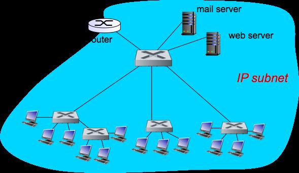
75 Institutional Network 75
 switches are link layer devices routers")
76 Switches vs. Routers both store-and-forward devices routers: network layer devices (examine network layer headers) switches are link layer devices routers maintain routing tables, implement routing algorithms switches maintain switch tables, implement filtering, learning algorithms 76

 must cross entire LAN")
77 VLANs: Motivation Consider the following scenario: CS user moves office to EE, but wants connect to CS switch? single broadcast domain: all layer-2 broadcast traffic (ARP, DHCP, unknown location of destination MAC address) must cross entire LAN security/privacy, efficiency issues 77


78 VLANs port-based VLAN: switch ports grouped (by switch management software) so that single physical switch operates as multiple virtual switches 78
 in practice vendors sell combined switches plus")
79 Port-Based VLAN traffic isolation: frames to/from ports 1-8 can only reach ports 1-8 can also define VLAN based on MAC addresses of endpoints, rather than switch port dynamic membership: ports can be dynamically assigned among VLANs forwarding between VLANS: done via routing (just as with separate switches) in practice vendors sell combined switches plus routers 79
 802.")
80 VLANs Spanning Multiple Switches trunk port: carries frames between VLANS defined over multiple physical switches frames forwarded within VLAN between switches can t be vanilla frames (must carry VLAN ID info) 802.1q protocol adds/removed additional header fields for frames forwarded between trunk ports 80

81 Next Time... Textbook Chapter Remember, you need to read it BEFORE you come to class! Homework: Project #3 assigned Prep for the midterm! 81
CSC 4900 Computer Networks: The Link Layer
 CSC 4900 Computer Networks: The Link Layer Professor Henry Carter Fall 2017 Last Time We talked about intra-as routing protocols: Which routing algorithm is used in RIP? OSPF? What techniques allow OSPF
CSC 4900 Computer Networks: Link Layer (2)
") CSC 4900 Computer Networks: Link Layer (2) Professor Henry Carter Fall 2017 Link Layer 6.1 Introduction and services 6.2 Error detection and correction 6.3 Multiple access protocols 6.4 LANs addressing,
CSC 4900 Computer Networks: Link Layer (2) Professor Henry Carter Fall 2017 Link Layer 6.1 Introduction and services 6.2 Error detection and correction 6.3 Multiple access protocols 6.4 LANs addressing,
Chapter 5 Link Layer and LANs
 Chapter 5 Link Layer and LANs Computer Networking: A Top Down Approach 4 th edition. Jim Kurose, Keith Ross Addison-Wesley, July 2007. All material copyright 1996-2007 J.F Kurose and K.W. Ross, All Rights
The Link Layer and LANs. Chapter 6: Link layer and LANs
 The Link Layer and LANs EECS3214 2018-03-14 4-1 Chapter 6: Link layer and LANs our goals: understand principles behind link layer services: error detection, correction sharing a broadcast channel: multiple
CS 455/555 Intro to Networks and Communications. Link Layer
 CS 455/555 Intro to Networks and Communications Link Layer Dr. Michele Weigle Department of Computer Science Old Dominion University mweigle@cs.odu.edu http://www.cs.odu.edu/~mweigle/cs455-s13 1 Link Layer
CMPE 150/L : Introduction to Computer Networks. Chen Qian Computer Engineering UCSC Baskin Engineering Lecture 16
 CMPE 150/L : Introduction to Computer Networks Chen Qian Computer Engineering UCSC Baskin Engineering Lecture 16 1 Final project demo Please do the demo next week to the TAs. So basically you may need
Chapter 5: Link layer
 Chapter 5: Link layer our goals: v understand principles behind link layer services: error detection, correction sharing a broadcast channel: multiple access link layer addressing local area networks:
Lecture 6 The Data Link Layer. Antonio Cianfrani DIET Department Networking Group netlab.uniroma1.it
 Lecture 6 The Data Link Layer Antonio Cianfrani DIET Department Networking Group netlab.uniroma1.it Link Layer: setting the context two physically connected devices: host-router, router-router, host-host,
Chapter 5 Link Layer and LANs
 Chapter 5 Link Layer and LANs A note on the use of these ppt slides: All material copyright 1996-2007 J.F Kurose and K.W. Ross, All Rights Reserved Computer Networking: A Top Down Approach 4 th edition.
Chapter V: Link Layer
 Chapter V: Link Layer UG3 Computer Communications & Networks (COMN) Myungjin Lee myungjin.lee@ed.ac.uk Slides copyright of Kurose and Ross Link layer services framing, link access: encapsulate datagram
Chapter 5 Link Layer. Computer Networking: A Top Down Approach. 6 th edition Jim Kurose, Keith Ross Addison-Wesley March 2012
 Chapter 5 Link Layer A note on the use of these ppt slides: We re making these slides freely available to all (faculty, students, readers). They re in PowerPoint form so you see the animations; and can
Lecture 6. Data Link Layer (cont d) Data Link Layer 1-1
 Data Link Layer 1-1") Lecture 6 Data Link Layer (cont d) Data Link Layer 1-1 Agenda Continue the Data Link Layer Multiple Access Links and Protocols Addressing Data Link Layer 1-2 Multiple Access Links and Protocols Two types
Lecture 6 Data Link Layer (cont d) Data Link Layer 1-1 Agenda Continue the Data Link Layer Multiple Access Links and Protocols Addressing Data Link Layer 1-2 Multiple Access Links and Protocols Two types
Lecture 5 The Data Link Layer. Antonio Cianfrani DIET Department Networking Group netlab.uniroma1.it
 Lecture 5 The Data Link Layer Antonio Cianfrani DIET Department Networking Group netlab.uniroma1.it Link Layer: setting the context two physically connected devices: host-router, router-router, host-host,
Topics. Link Layer Services (more) Link Layer Services LECTURE 5 MULTIPLE ACCESS AND LOCAL AREA NETWORKS. flow control: error detection:
 Link Layer Services LECTURE 5 MULTIPLE ACCESS AND LOCAL AREA NETWORKS. flow control: error detection:") 1 Topics 2 LECTURE 5 MULTIPLE ACCESS AND LOCAL AREA NETWORKS Multiple access: CSMA/CD, CSMA/CA, token passing, channelization LAN: characteristics, i basic principles i Protocol architecture Topologies
1 Topics 2 LECTURE 5 MULTIPLE ACCESS AND LOCAL AREA NETWORKS Multiple access: CSMA/CD, CSMA/CA, token passing, channelization LAN: characteristics, i basic principles i Protocol architecture Topologies
CSC 401 Data and Computer Communications Networks
 CSC 401 Data and Computer Communications Networks Link Layer: Intro, Errors, Multiple Access Sec 6.1, 6.2, 6.3 Prof. Lina Battestilli Fall 2017 Chapter 6: Link layer Goals: understand principles behind
Adaptors Communicating. Link Layer: Introduction. Parity Checking. Error Detection. Multiple Access Links and Protocols
 Link Layer: Introduction daptors ommunicating Terminology: hosts and routers are nodes communication channels that connect adjacent nodes along communication path are links wired links wireless links LNs
Lecture 8 Link Layer: functionality, error detection, media access algorithm
 Lecture 8 Link Layer: functionality, error detection, media access algorithm From Kurose & Ross Book slightly modified by Romaric Duvignau duvignau@chalmers.se Thanks and enjoy! JFK/KWR All material copyright
Link Layer and LANs 안상현서울시립대학교컴퓨터 통계학과.
 Link Layer and LANs 안상현서울시립대학교컴퓨터 통계학과 ahn@venus.uos.ac.kr Data Link Layer Goals: understand principles behind data link layer services: error detection, correction sharing a broadcast channel: multiple
Computer Networks. Today. Principles of datalink layer services Multiple access links Adresavimas, ARP LANs Wireless LANs VU MIF CS 1/48 2/48
 Computer Networks VU MIF CS 1/48 Today Principles of datalink layer services Multiple access links Adresavimas, ARP LANs Wireless LANs 2/48 1 Link layer: introduction terminology: hosts and routers: nodes
Master Course Computer Networks IN2097
 Chair for Network Architectures and Services Prof. Carle Department for Computer Science TU München Master Course Computer Networks IN2097 Prof. Dr.-Ing. Georg Carle Christian Grothoff, Ph.D. Dr. Nils
Data Link Layer: Multi Access Protocols
 Digital Communication in the Modern World Data Link Layer: Multi Access Protocols http://www.cs.huji.ac.il/~com1 com1@cs.huji.ac.il Some of the slides have been borrowed from: Computer Networking: A Top
Data Link Layer. Our goals: understand principles behind data link layer services: instantiation and implementation of various link layer technologies
 Data Link Layer Our goals: understand principles behind data link layer services: link layer addressing instantiation and implementation of various link layer technologies 1 Outline Introduction and services
Principles behind data link layer services
 Data link layer Goals: Principles behind data link layer services Error detection, correction Sharing a broadcast channel: Multiple access Link layer addressing Reliable data transfer, flow control: Done!
Links Reading: Chapter 2. Goals of Todayʼs Lecture. Message, Segment, Packet, and Frame
 Links Reading: Chapter 2 CS 375: Computer Networks Thomas Bressoud 1 Goals of Todayʼs Lecture Link-layer services Encoding, framing, and error detection Error correction and flow control Sharing a shared
CC451 Computer Networks
 CC451 Computer Networks Lecture 9 Link Layer 5: DataLink Layer 5-1 Chapter 5 Link Layer and LANs A note on the use of these ppt slides: We re making these slides freely available to all (faculty, students,
Chapter 5 Link Layer and LANs
 Chapter 5 Link Layer and LANs A note on the use of these ppt slides: We re making these slides freely available to all (faculty, students, readers). They re in PowerPoint form so you can add, modify, and
Link Layer and LANs. Our Goals. Link Layer
 Link Layer and LANs Instructor: Anirban Mahanti Office: ICT 745 Email: mahanti@cpsc.ucalgary.ca Class Location: ICT 121 Lectures: MWF 12:00 12:50 hours Notes derived from Computer Networking: A Top Down
Chapter 6 The Link Layer and LANs
 Chapter 6 The Link Layer and LANs A note on the use of these Powerpoint slides: We re making these slides freely available to all (faculty, students, readers). They re in PowerPoint form so you see the
Chapter V: Link Layer
 Chapter V: Link Layer UG3 Computer Communications & Networks (COMN) Myungjin Lee myungjin.lee@ed.ac.uk Slides copyright of Kurose and Ross Link layer: introduction terminology: hosts and routers: nodes
Master Course Computer Networks IN2097
 Chair for Network Architectures and Services Prof. Carle Department for Computer Science TU München Master Course Computer Networks IN2097 Prof. Dr.-Ing. Georg Carle Christian Grothoff, Ph.D. Chair for
Link Layer and LANs. CMPS 4750/6750: Computer Networks
 Link Layer and LANs CMPS 4750/6750: Computer Networks 1 Outline overview (6.1) multiple access (6.3) link addressing: ARP (6.4.1) a day in the life of a web request (6.7) 2 Link layer: introduction terminology:
Principles behind data link layer services:
 Data link layer Goals: Principles behind data link layer services: Error detection, correction Sharing a broadcast channel: Multiple access Link layer addressing Reliable data transfer, flow control Example
Principles behind data link layer services:
 Data link layer Goals: Principles behind data link layer services: Error detection, correction Sharing a broadcast channel: Multiple access Link layer addressing Reliable data transfer, flow control Example
Adaptors Communicating. Link Layer: Introduction. Parity Checking. Error Detection. Multiple Access Links and Protocols
 Link Layer: Introduction daptors ommunicating hosts and routers are nodes links connect nodes wired links wireless links layer-2 packet is a frame, encapsulates datagram datagram controller sending host
Module 10 Data Link Layer CS655! 10-1!
 Module 10 Data Link Layer CS655! 10-1! Please note: Most of these slides come from this book. Note their copyright notice below! A note on the use of these ppt slides: We re making these slides freely
CS 43: Computer Networks Switches and LANs. Kevin Webb Swarthmore College December 5, 2017
 CS 43: Computer Networks Switches and LANs Kevin Webb Swarthmore College December 5, 2017 Ethernet Metcalfe s Ethernet sketch Dominant wired LAN technology: cheap $20 for NIC first widely used LAN technology
Principles behind data link layer services:
 Data Link Layer Goals: Principles behind data link layer services: Error detection, correction Sharing a broadcast channel: multiple access Link layer addressing Reliable data transfer, flow control: Done!
transferring datagram from one node data-link layer has responsibility of to adjacent node over a link 5-1 TDTS06 Computer networks
 TDTS06 Computer networks Lecture 7: The link layer I Link Layer: Introduction Some terminology: hosts and routers are nodes communication channels that connect adjacent nodes along communication path are
ECE 4450:427/527 - Computer Networks Spring 2017
 ECE 4450:427/527 - Computer Networks Spring 2017 Dr. Nghi Tran Department of Electrical & Computer Engineering Lecture 5.4: Multiple Access Protocols Dr. Nghi Tran (ECE-University of Akron) ECE 4450:427/527
Outline. Introduction to Networked Embedded Systems - Embedded systems Networked embedded systems Embedded Internet - Network properties
 Outline Introduction to Networked Embedded Systems - Embedded systems Networked embedded systems Embedded Internet - Network properties Layered Network Architectures - OSI framework descriptions of layers
CS 455/555 Intro to Networks and Communications. Link Layer Addressing, Ethernet, and a Day in the Life of a Web Request
 CS 455/555 Intro to Networks and Communications Link Layer Addressing, ernet, and a Day in the Life of a Web Request Dr. Michele Weigle Department of Computer Science Old Dominion University mweigle@cs.odu.edu
Summary of MAC protocols
 Summary of MAC protocols What do you do with a shared media? Channel Partitioning, by time, frequency or code Time Division, Code Division, Frequency Division Random partitioning (dynamic) ALOHA, S-ALOHA,
Link Layer: Introduction. Chapter 5 Link Layer & LANS. Link layer: context. Link Layer Services
 Chapter 5 Link Layer & LNS Link Layer: Introduction Some terminology: hosts and routers are nodes communication channels that connect adjacent nodes along communication path are links wired links wireless
Broadcast Links, Addressing and Media Access Control. Link Layer B. Link and Physical Layers. MAC Addresses
 roadcast Links, ddressing and Media ccess Control Message M C Message M Link Layer In a broadcast, there are two additional issues that must be resolved How do the nodes agree on who gets to use the next?
The Link Layer and LANs: Ethernet and Swiches
 The Link Layer and LNs: Ethernet and Swiches EECS3214 2018-03-21 Link layer, LNs: outline 6.1 introduction, services 6.2 error detection, correction 6.3 multiple access protocols 6.4 LNs addressing, RP
Lecture 6 - Link layer. Lecture 5 Review. Link Layer. Introduction, Services. Notes. Notes. Notes. Notes. Networks and Security. Jacob Aae Mikkelsen
 Lecture 6 - Link layer Networks and Security Jacob Aae Mikkelsen IMADA October 21, 2013 October 21, 2013 1 / 91 Lecture 5 Review Explain in short the following abbreviations, and the concept behind it.
Chapter 5 Link Layer. Computer Networking: A Top Down Approach. 6 th edition Jim Kurose, Keith Ross Addison-Wesley March 2012
 Chapter 5 Link Layer Computer Networking: A Top Down Approach 6 th edition Jim Kurose, Keith Ross Addison-Wesley March 2012 All material copyright 1996-2012 J.F Kurose and K.W. Ross, All Rights Reserved
Medium Access Protocols
 Medium Access Protocols Summary of MAC protocols What do you do with a shared media? Channel Partitioning, by time, frequency or code Time Division,Code Division, Frequency Division Random partitioning
Link Layer: Introduction. Chapter 5 Link Layer & LANS. Link layer: context. Link Layer Services
 Chapter 5 Link Layer & LANS Link Layer: Introduction Some terminology: hosts and routers are nodes communication channels that connect adjacent nodes along communication path are links wired links wireless
Chapter 5 Link Layer. Computer Networking: A Top Down Approach. 6 th edition Jim Kurose, Keith Ross Addison-Wesley March 2012
 Chapter 5 Link Layer A note on the use of these ppt slides: We re making these slides freely available to all (faculty, students, readers). They re in PowerPoint form so you see the animations; and can
Chapter 6: Link layer and LANs. Link layer, LANs: outline. Link layer: introduction. Link layer: context. Link layer services (more)
") Chapter 6: Link layer and LANs our goals: understand principles behind layer services: error detection, sharing a broadcast channel: multiple access layer addressing local area networks: ernet, VLANs instantiation,
Chapter 6: Link layer and LANs our goals: understand principles behind layer services: error detection, sharing a broadcast channel: multiple access layer addressing local area networks: ernet, VLANs instantiation,
1-1. Switching Networks (Fall 2010) EE 586 Communication and. November 8, Lecture 30
 EE 586 Communication and. November 8, Lecture 30") EE 586 Communication and Switching Networks (Fall 2010) Lecture 30 November 8, 2010 1-1 Announcements Quiz on Wednesday Next Monday hands-on training on Contiki OS Bring your laptop 4-2 Multiple Access
EE 586 Communication and Switching Networks (Fall 2010) Lecture 30 November 8, 2010 1-1 Announcements Quiz on Wednesday Next Monday hands-on training on Contiki OS Bring your laptop 4-2 Multiple Access
Review. Error Detection: CRC Multiple access protocols. LAN addresses and ARP Ethernet. Slotted ALOHA CSMA/CD
 Review Error Detection: CRC Multiple access protocols Slotted ALOHA CSMA/CD LAN addresses and ARP Ethernet Some slides are in courtesy of J. Kurose and K. Ross Overview Ethernet Hubs, bridges, and switches
Chapter 5 Link Layer. Link Layer 5-1
 Chapter 5 Link Layer Link Layer 5-1 Link layer: introduction terminology: hosts and routers: nodes communication channels that connect adjacent nodes along communication path: links wired links wireless
Lecture 9 The Data Link Layer part II. Antonio Cianfrani DIET Department Networking Group netlab.uniroma1.it
 Lecture 9 The Data Link Layer part II Antonio Cianfrani DIET Department Networking Group netlab.uniroma1.it Physical Addresses Physical (or LAN or MAC) address: 48 bit string Hexadecimal representation
Links. CS125 - mylinks 1 1/22/14
 Links 1 Goals of Today s Lecture Link-layer services Encoding, framing, and error detection Error correction and flow control Sharing a shared media Channel partitioning Taking turns Random access Shared
Lecture 8 The Data Link Layer part I. Antonio Cianfrani DIET Department Networking Group netlab.uniroma1.it
 Lecture 8 The Data Link Layer part I Antonio Cianfrani DIET Department Networking Group netlab.uniroma1.it Link Layer: setting the context two physically connected devices: host-router, router-router,
Module 4 Data Link Layer CS655! 4-1!
 Module 4 Data Link Layer CS655! 4-1! Please note: Most of these slides come from this book. Note their copyright notice below! A note on the use of these ppt slides: We re making these slides freely available
CSCI Computer Networks Fall 2016
 source: computer-networks-webdesign.com CSCI 4760 - Computer Networks Fall 2016 Instructor: Prof. Roberto Perdisci perdisci@cs.uga.edu These slides are adapted from the textbook slides by J.F. Kurose and
Chapter 4 Network Layer
 Chapter 4 Network Layer Computer Networking: A Top Down Approach 6 th edition Jim Kurose, Keith Ross Addison-Wesley March 2012 Slides adopted from original ones provided by the textbook authors. Network
CSCI Computer Networks Spring 2017
 source: computer-networks-webdesign.com CSCI 6760 - Computer Networks Spring 2017 Instructor: Prof. Roberto Perdisci perdisci@cs.uga.edu These slides are adapted from the textbook slides by J.F. Kurose
LINK LAYER AND LANS 1
 LINK LAYER AND LANS 1 GOALS Understand principles behind link layer services: error detection, correction link layer addressing local area networks: Ethernet, VLANs, and data center networks Instantiation,
SC250 Computer Networking I. Link Layer. Prof. Matthias Grossglauser LCA/I&C.
 SC250 Computer Networking I Link Layer Prof. Matthias Grossglauser LCA/I&C http://lcawww.epfl.ch 1 Objectives Understand principles behind data link layer services: sharing a broadcast channel: multiple
Chapter 5: The Data Link Layer. Chapter 5 Link Layer and LANs. Ethernet. Link Layer. Star topology. Ethernet Frame Structure.
 hapter 5 Link Layer and LNs omputer Networking: Top Down pproach 5 th edition. Jim Kurose, Keith Ross ddison-wesley, pril 2009. hapter 5: The Data Link Layer Our goals: understand principles behind data
Chapter 4. DataLink Layer. Reference: Computer Networking: A Top Down Approach 4 th edition. Jim Kurose, Keith Ross Addison-Wesley, July 2007.
 Chapter 4 DataLink Layer Reference: Computer Networking: A Top Down Approach 4 th edition. Jim Kurose, Keith Ross Addison-Wesley, July 2007. DataLink Layer Link Layer 4.1 Link-Layer Addressing 4.2 Ethernet
Link Layer: Introduction. Chapter 5 Link Layer & LANS. Link layer: context. Link Layer Services
 Chapter 5 Link Layer & LNS Link Layer: Introduction Some terminology: hosts and routers are nodes communication channels that connect adjacent nodes along communication path are links wired links wireless
INTRODUCTION, SERVICES. Data-link layer has responsibility of transferring datagram from one node to physically adjacent node over a link
 LINK LAYER 1 GOALS Understand principles behind link layer services: error detection, correction link layer addressing local area networks: Ethernet, VLANs, and data center networks 2 INTRODUCTION, SERVICES
CMPE 150/L : Introduction to Computer Networks. Chen Qian Computer Engineering UCSC Baskin Engineering Lecture 18
 CMPE 150/L : Introduction to Computer Networks Chen Qian Computer Engineering UCSC Baskin Engineering Lecture 18 1 Final project demo Please do the demo THIS week to the TAs. Or you are allowed to use
Chapter 5: The Data Link Layer
 Chapter 5: The Data Link Layer Our goals: principles behind data link layer services: error detection, correction sharing a broadcast channel: multiple access link layer addressing reliable data transfer,
Chapter 6 The Link Layer and LANs
 Chapter 6 The Link Layer and LANs Chapter 6: Link layer and LANs our goals: understand principles behind link layer services: error detection, correction sharing a broadcast channel: multiple access link
CMPE 150: Introduction to Computer Networks
 CMPE 150: Introduction to Computer Networks Katia Obraczka Computer Engineering UCSC Baskin Engineering Lecture 18 Project Deliverables: Project demo. Code (documented). Demo schedule: Judith: Monday 03.18
Chapter 5: DataLink Layer
 Chapter 5: DataLink Layer Course on Computer Communication and Networks, CTH/GU The slides are adaptation of the slides made available by the authors of the course s main textbook Slides with darker background
Computer Network Fundamentals Spring Week 3 MAC Layer Andreas Terzis
 Computer Network Fundamentals Spring 2008 Week 3 MAC Layer Andreas Terzis Outline MAC Protocols MAC Protocol Examples Channel Partitioning TDMA/FDMA Token Ring Random Access Protocols Aloha and Slotted
Chapter 5 Data Link Layer
 Chapter 5 Data Link Layer Reti degli Elaboratori Canale AL Prof.ssa Chiara Petrioli a.a. 2013/2014 We thank for the support material Prof. Kurose-Ross All material copyright 1996-2012 J.F Kurose and K.W.
Chapter 5 Link Layer. Computer Networking: A Top Down Approach. 6 th edition Jim Kurose, Keith Ross Addison-Wesley March 2012
 Chapter 5 Link Layer A note on the use of these ppt slides: We re making these slides freely available to all (faculty, students, readers). They re in PowerPoint form so you see the animations; and can
MULTIPLE ACCESS PROTOCOLS 2. 1
 MULTIPLE ACCESS PROTOCOLS AND WIFI 1 MULTIPLE ACCESS PROTOCOLS 2. 1 MULTIPLE ACCESS LINKS, PROTOCOLS Two types of links : point-to-point broadcast (shared wire or medium) POINT-TO-POINT PPP for dial-up
Link layer: introduction
 Link layer: introduction terminology: hosts and routers: nodes communication channels that connect adjacent nodes along communication path: links wired links wireless links LANs layer-2 packet: frame,
Chapter 5 Link Layer. Computer Networking: A Top Down Approach. 6 th edition Jim Kurose, Keith Ross Addison-Wesley March 2012
 Chapter 5 Link Layer Computer Networking: A Top Down Approach 6 th edition Jim Kurose, Keith Ross Addison-Wesley March 2012 All material copyright 1996-2012 J.F Kurose and K.W. Ross, All Rights Reserved
Chapter 6 The Link Layer and LANs
 Chapter 6 The Link Layer and LANs A note on the use of these Powerpoint slides: We re making these slides freely available to all (faculty, students, readers). They re in PowerPoint form so you see the
CS 3516: Advanced Computer Networks
 Welcome to CS 3516: Advanced Computer Networks Prof. Yanhua Li Time: 9:00am 9:50am M, T, R, and F Location: Fuller 320 Fall 2017 A-term 1 Some slides are originally from the course materials of the textbook
Chapter 5: Link layer
 Chapter 5: Link layer our goals: v understand principles behind link layer services: error detection, correction sharing a broadcast channel: multiple access link layer addressing local area networks:
Medium Access Control
 Medium Access Control All material copyright 1996-2009 J.F Kurose and K.W. Ross, All Rights Reserved 5: DataLink Layer 5-1 Link Layer Introduction and services Multiple access protocols Ethernet Wireless
Chapter 6 The Link Layer and LANs
 Chapter 6 The Link Layer and LANs Andrei Gurtov TDTS04/TDTS11/TDDD93 All material copyright 1996-2016 J.F Kurose and K.W. Ross, All Rights Reserved Computer Networking: A Top Down Approach 7 th edition
Chapter 6 The Link Layer and LANs
 Chapter 6 The Link Layer and LANs Andrei Gurtov All material copyright 1996-2016 J.F Kurose and K.W. Ross, All Rights Reserved Computer Networking: A Top Down Approach 7 th edition Jim Kurose, Keith Ross
CS 43: Computer Networks. 27: Media Access Contd. December 3, 2018
 CS 43: Computer Networks 27: Media Access Contd. December 3, 2018 Last Class The link layer provides lots of functionality: addressing, framing, media access, error checking could be used independently
Link Layer and Ethernet
 Link Layer and Ethernet 14-740: Fundamentals of Computer Networks Bill Nace Material from Computer Networking: A Top Down Approach, 6 th edition. J.F. Kurose and K.W. Ross traceroute Data Link Layer Multiple
CS 43: Computer Networks Media Access. Kevin Webb Swarthmore College November 30, 2017
 CS 43: Computer Networks Media Access Kevin Webb Swarthmore College November 30, 2017 Multiple Access Links & Protocols Two classes of links : point-to-point dial-up access link between Ethernet switch,
Lecture 19. Principles behind data link layer services Framing Multiple access protocols
 Link Layer Lecture 19 Principles behind data link layer services Framing Multiple access protocols ALOHA *The slides are adapted from ppt slides (in substantially unaltered form) available from Computer
Chapter 5 Link Layer and LANs
 Chapter 5 Link Layer and LANs Computer Networking: A Top Down Approach Featuring the Internet, A note on the use of these ppt slides: We re making these slides freely available to all (faculty, students,
Link Layer and Ethernet
 Link Layer and Ethernet 14-740: Fundamentals of Computer Networks Bill Nace Material from Computer Networking: A Top Down Approach, 6 th edition. J.F. Kurose and K.W. Ross traceroute Data Link Layer Multiple
Chapter 5 Data Link Layer
 Chapter 5 Data Link Layer Reti di Elaboratori Corso di Laurea in Informatica Università degli Studi di Roma La Sapienza Canale A-L Prof.ssa Chiara Petrioli Parte di queste slide sono state prese dal materiale
Chapter 6 The Data Link layer
 Chapter 6 The Data Link layer 6.1 introduction, services 6.2 error detection, correction 6.3 multiple access protocols 6.4 LANs addressing, ARP Ethernet layer-2 switches VLANS 6.5 link virtualization:
High Level View. EE 122: Ethernet and Random Access protocols. Medium Access Protocols
 High Level View EE 122: Ethernet and 802.11 Ion Stoica September 18, 2002 Goal: share a communication medium among multiple hosts connected to it Problem: arbitrate between connected hosts Solution goals:
Multiple Access Links and Protocols
 Multiple Access Links and Protocols Two types of links : point-to-point PPP for dial-up access point-to-point link between Ethernet switch and host broadcast (shared wire or medium) old-fashioned Ethernet
Link layer, LANs: outline. Chapter 5-1 Link Layer. Link layer: introduction. Link layer services
 Chapter 5 Link Layer Computer Networking: A Top Down Approach 6 th edition Jim Kurose, Keith Ross Addison-Wesley March 2012 Link layer, LANs: outline 5.1 introduction, services 5.2 error detection, correction
Chapter 6 The Link Layer and LANs
 Chapter 6 The Link Layer and LANs A note on the use of these Powerpoint slides: We re making these slides freely available to all (faculty, students, readers). They re in PowerPoint form so you see the
Computer Communication Networks Link
 Computer Communication Networks Link ICEN/ICSI 416 Fall 2017 Prof. Dola Saha 1 Link layer and LANs our goals: understand principles behind link layer services: error detection, correction sharing a broadcast
Computer Networks Medium Access Control. Mostafa Salehi Fall 2008
 Computer Networks Medium Access Control Mostafa Salehi Fall 2008 2008 1 Outline Issues ALOHA Network Ethernet Token Ring Wireless 2 Main Issues Local Area Network (LAN) : Three or more machines are physically
Links. Error Detection. Link Layer. Multiple access protocols. Nodes Links Frame. Shared channel Problem: collisions How nodes share a channel
 Link Layer Error Detection Nodes Links Frame R yclic Redundancy hecksum Parity its More about this in exercise! Data Link Layer -1 Data Link Layer -2 Links Two types of links : point-to-point broadcast
EE 122: Ethernet and
 EE 122: Ethernet and 802.11 Ion Stoica September 18, 2002 (* this talk is based in part on the on-line slides of J. Kurose & K. Rose) High Level View Goal: share a communication medium among multiple hosts