Long Term Evolution - Advanced (LTE-Advanced)
|
|
|
- Stanley Hines
- 5 years ago
- Views:
Transcription
1 Long Term Evolution - Advanced (LTE-Advanced)
2 OFDMA & SC-OFDMA LTE employs Orthogonal Frequency Division Multiple Access (OFDMA) for downlink data transmission Single Carrier FDMA (SC-FDMA) for uplink transmission

3 FDM vs. OFDM Improved spectral efficiency The amplitude of each sub-carrier oscillates either side of zero and crosses through zero at regular intervals The peak response of one sub-carrier coincides with zeros of all the others
 and thus increase battery")
4 LTE Uplink (SC-FDMA) SC-FDMA is a new single carrier multiple access technique which has similar structure and performance to OFDMA A salient advantage of SC-FDMA over OFDM is low to Peak to Average Power Ratio (PAPR) and thus increase battery life
5 OFDM Time Frequency Representation Fourier analysis converts a signal from its original domain (often time or space) to a representation in the frequency domain and vice versa.
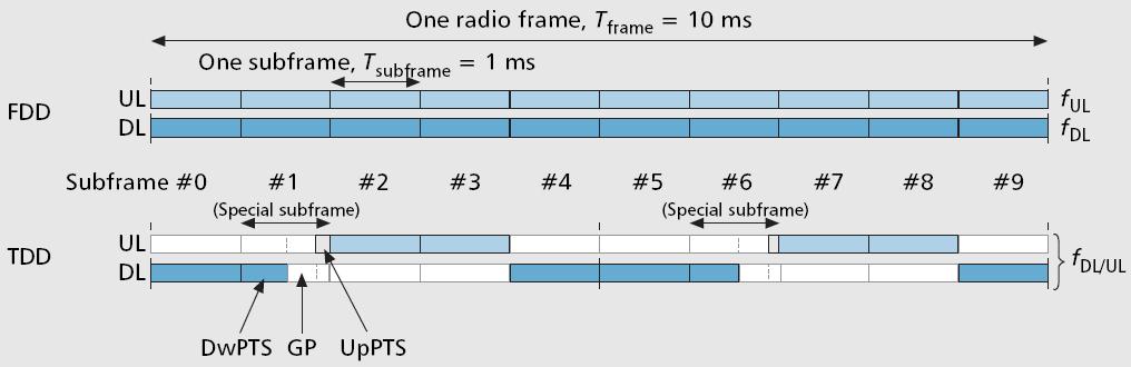
6 Frame Structure Two radio frame structures defined Frame structure type 1 (FS1): FDD Frame structure type 2 (FS2): TDD 1 frame has duration of 10 ms = 10 subframes 1 subframes has duration of 1 ms = 2 slots 1 slot has duration of 0.5 ms 1 subcarrier has bandwidth of 15 khz A resource block (RB) spans 12 subcarriers of 180 khz over a slot duration of 0.5 ms
7 Frame Structure Type 1 (FDD) 1 frame has duration of 10 ms = 10 subframes 1 subframes has duration of 1 ms = 2 slots 1 slot has duration of 0.5 ms
8 Frame Structure Type 2 (TDD) 1 frame has duration of 10 ms = 10 subframes 1 subframes has duration of 1 ms = 2 slots 1 slot has duration of 0.5 ms
9
 1 subcarrier has bandwidth of 15 khz A resource block (RB) spans 12 subcarriers of 180 khz")
10 Resource Grid 0.5ms 180kHz 1 slot has duration of 0.5 ms (each symbol 66.7 us) 1 subcarrier has bandwidth of 15 khz A resource block (RB) spans 12 subcarriers of 180 khz over a slot duration of 0.5 ms
11 In OFDMA, the BS shares its resources by transmitting to the mobiles at different times and frequencies, so as to meet the requirements of individual applications
12 Example UE1 receiving a voice over IP stream the data rate, and the num of sub-carriers, is low but constant UE2 receiving a stream of non real time packet data the average data rate is higher the data come in bursts, so the num of sub-carriers can vary
13 The BS can also respond to frequency dependent fading, by allocating subcarriers on which the mobile is receiving a strong signal UE3 is receiving a VoIP stream, but it is also affected by frequency dependent fading the BS allocates sub-carriers on which the mobile is receiving a strong signal, and changes this allocation as the fading pattern changes
14 System Architecture
15
 in the outside world such as Internet, private corporate networks or IMS Interfaces between different parts of the system are denoted Uu, S1 and")
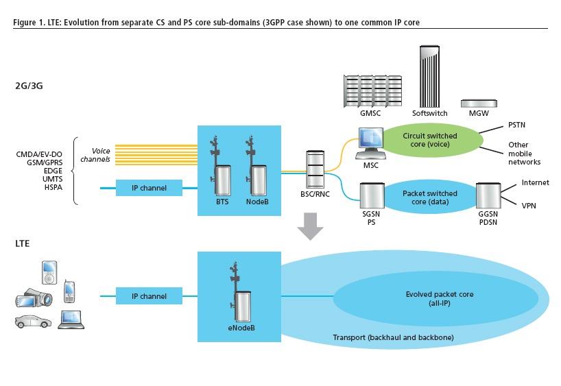
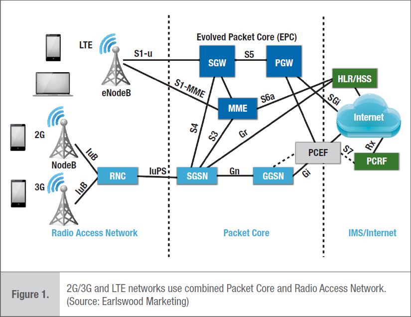
16 Evolved Packet System (EPS) has three main components User Equipment (UE) Evolved UMTS Terrestrial Radio Access Network (E- UTRAN) Evolved Packet Core (EPC) EPC communicates with Packet Data Networks (PDN) in the outside world such as Internet, private corporate networks or IMS Interfaces between different parts of the system are denoted Uu, S1 and SGi
17 Evolved UMTS Terrestrial Radio Access Network (E-UTRAN) Handles the radio communications between mobile and EPC Just has one component, evolved Node B (enb)
18 enb has two main functions enb sends radio transmissions to all its mobiles on the downlink and receives transmissions from them on the uplink, using the analogue and digital signal processing functions of the LTE air interface enb controls the low-level operation of all its mobiles, by sending them signaling messages such as handover commands that relate to those radio transmissions enb combines the earlier functions of Node B and Radio Network Controller (RNC), to reduce the latency that arises when the mobile exchanges information with the network
19 enb interfaces enb is connected to EPC by S1 interface enb is connected to nearby enb by X2 interface mainly used for signaling and packet forwarding during handover X2 interface is optional - S1 interface can also handle all the functions of X2, though indirectly and more slowly
20 Home enb (HeNB) a base station to provide femtocell coverage within the home belongs to a Closed Subscriber Group (CSG) and can only be accessed by mobiles with a USIM that also belongs to the CSG HeNB can be connected directly to the EPC in the same way as any other base station, or by way of an intermediate device known as a home enb gateway that collects the information from several HeNBs Only control one cell, and do not support X2 interface until Release 10
21 Evolved Packet Core Main components of EPC P-GW:Packet Data Network (PDN) Gateway S-GW:Serving Gateway MME:Mobility Management Entity Home Subscriber Server (HSS) a central database that contains information about all the network operator s subscribers the components of LTE carried forward from UMTS and GSM
22 Main components of the EPC
23 Packet Data Network (PDN) Gateway (P-GW) EPC s point of contact with outside world through the SGi interface, each P- GW exchanges data with one or more external devices or PDNs, such as network operator s servers, Internet or IMS each packet data network (PDN) is identified by an Access Point Name (APN) a network operator typically uses a handful of different APNs, e.g., one for its own server and one for Internet
24 Serving Gateway (S- GW) Acts as a router, and forwards data between enb and P-GW each mobile is assigned to a single S-GW but the S-GW can be changed if the mobile moves sufficiently far
25 Mobility Management Entity (MME) controls the high-level operation of the mobile, by sending it signaling messages about issues such as security and the management of data streams that are unrelated to radio communications each mobile is assigned to a single MME which is known as its serving MME that can be changed if the mobile moves sufficiently far
26 Comparison with UMTS and GSM P-GW has the same role as the gateway GPRS support node (GGSN) S-GW and MME handle the data routing and signaling functions of the serving GPRS support node (SGSN) Splitting SGSN in two makes it easier for an operator to scale the network in response to an increased load add more S-GWs as the traffic increases add more MMEs to handle an increase in the number of mobiles S1 interface has two components - S1-U interface carries traffic for S- GW - S1-MME interface carries signaling messages for MME
27 EPC has some other components Cell Broadcast Centre (CBC) previously used by UMTS for Cell Broadcast Service (CBS) in LTE, the equipment is re-used for a service known as Earthquake and Tsunami Warning System (ETWS) Equipment Identity Register (EIR) also inherited from UMTS, and lists the details of lost or stolen mobiles
28 Roaming Architecture Roaming allows users to move outside their network operators coverage area by using the resources from two different networks Relies on the existence of a roaming agreement, which defines how the operators will share the resulting revenue Architecture of LTE for a roaming mobile
29 If a user is roaming Home Subscriber Server (HSS) is always in the home network the mobile, E-UTRAN, MME and S-GW are always in the visited network P-GW can be in two places Home routed traffic P-GW lies in the home network, through which all the user s traffic is all routed allows the home network operator to - see all the traffic - charge the user for it directly can be inefficient if the user is traveling overseas, particularly during a voice call with another user nearby Local breakout P-GW is located in the visited network
30 The interface between S-GW and P-GWs is S5/S8 S5: if two devices are in the same network S8: if two devices are in different networks For mobiles that are not roaming S-GW and P-GWs can be integrated into a single device, so that the S5/S8 interface vanishes altogether
31 Protocol Model The protocol stack has two planes user plane protocols handle data that are of interest to the users control plane protocols handle signaling messages that are only of interest to the network elements themselves High level protocol architecture of LTE
32 The protocol stack also has two main layers upper layer manipulates information in a way that is specific to LTE in the E-UTRAN, known as radio network layer lower layer transports information from one point to another in the E-UTRAN, known as transport network layer upper lower High level protocol architecture of LTE

33 There are then three types of protocol signaling protocols define a language by which two devices can exchange signaling messages with each other user plane protocols manipulate the data in the user plane, most often to help route the data within the network High level protocol architecture of LTE underlying transport protocols transfer data and signaling messages from one point to another
 Non Access Stratum (NAS) High-level signaling messages lie in NAS and are transported using AS")
34 On the air interface, there is an extra level of complexity MME controls the high-level behavior of mobile by sending it signaling messages no direct path between MME and mobile The access stratum and non access stratum on the air interface the air interface is divided into Access Stratum (AS) Non Access Stratum (NAS) High-level signaling messages lie in NAS and are transported using AS protocols of S1 and Uu interfaces
35 Air Interface Transport Protocols The air interface, Uu, lies between mobile and BS The air interface s transport protocols starting at the bottom physical layer contains the digital and analogue signal processing functions that the mobile and BS use to send and receive information Transport protocols used on the air interface
36 The next three protocols make up data link layer, the layer 2 of OSI model Packet Data Convergence Protocol (PDCP) carries out higher-level transport functions that are related to header compression and security Radio Link Control (RLC) protocol maintains the data link between the two devices, e.g., by ensuring reliable delivery for data streams that need to arrive correctly Transport protocols used on the air interface Medium Access Control (MAC) protocol carries out low-level control of the physical layer, particularly by scheduling data transmissions between mobile and BS
37 Fixed Network Transport Protocols Each interface in the fixed network uses standard IETF transport protocols These interfaces use protocols from layers 1 to 4 of the usual OSI model The transport network can use any suitable protocols for layers 1 and 2, such as Ethernet Every network element is then associated with an IP address, and the fixed network uses the Internet Protocol (IP) to route information from one element to another across underlying transport network Transport protocols used by the fixed network
38 LTE supports both IPv4 and IPv6 for this task in the EPC, support of IPv4 is mandatory and support of IPv6 is recommended in the radio access network, use either or both of the two protocols Transport protocols used by the fixed network
39 The transport layer protocol across the interface between each individual pair of network elements User Datagram Protocol (UDP) just sends data packets from one network element to another Transmission Control Protocol (TCP) re-transmits packets if they arrive incorrectly Stream Control Transmission Protocol (SCTP) based on TCP, but includes extra features that make it more suitable for the delivery of signaling messages
40 User plane always uses UDP as its transport protocol, to avoid delaying the data Control plane its choice depends on the overlying signaling protocol
41 User Plane Protocols LTE user plane contains mechanisms to forward data correctly between mobile and P-GW respond quickly to changes in the mobile s location These mechanisms are implemented by user plane protocols User plane protocols used by LTE
42 Most of the user plane interfaces use a 3GPP protocol known as GPRS Tunneling Protocol User part (GTP-U) GTPv1-U LTE uses version 1 of the protocol along with the 2G and 3G packet switched domains from Release 99 GTPv0-U earlier 2G networks used version 0 User plane protocols used by LTE
43 Between S-GW and P-GW, the S5/S8 user plane has an alternative implementation, known as Generic Routing Encapsulation (GRE) GTP-U and GRE forward packets from one network element to another using a technique known as tunneling
44 Signaling Protocols LTE uses a large number of signaling protocols
45 Radio Resource Control (RRC) protocol BS controls a mobile s radio communications S1 Application Protocol (S1-AP) MME controls BSs X2 application protocol (X2-AP) communication between two BSs
46 MME controls a mobile s high-level behavior using EPS Session Management (ESM) controls the data streams through which a mobile communicates with the outside world EPS Mobility Management (EMM) handles internal bookkeeping within EPC The network transports EMM and ESM messages by embedding them into lower-level RRC and S1-AP messages and then using the transport mechanisms of the Uu and S1 interfaces
47 Inside the EPC, HSS and MME communicate using a protocol based on Diameter Basic Diameter protocol a standard IETF protocol for authentication, authorization and accounting based on an older protocol known as Remote Authentication Dial In User Service (RADIUS) can be enhanced for use in specific applications: the implementation of Diameter on the S6a interface
48 Most of the other EPC interfaces use a 3GPP protocol known as GPRS Tunneling Protocol Control part (GTP-C) control plane LTE uses version 2 of the protocol, GTPv2-C If the S5/S8 user plane is using GRE, then its control plane uses a signaling protocol known as Proxy Mobile IPv6 (PMIPv6) PMIPv6 is a standard IETF protocol for the management of packet forwarding, in support of mobile devices such as laptops user plane
49 Operators of legacy 3GPP networks control plane prefer GTP-U and GTP-C, for consistency with their previous systems and with other signaling interfaces in the EPC Operators of non 3GPP networks prefer GRE and PMIP, which are standard IETF protocols, and which are also used for inter-operation between LTE and non 3GPP technologies user plane
50 Signaling Radio Bearers LTE uses three special radio bearers, known as Signaling Radio Bearers (SRBs), to carry signaling messages between mobile and BS Each of the signaling radio bearers (SRB) is associated with a specific configuration of the air interface protocols, so that the mobile and BS can agree on how the signaling messages should be transmitted and received Signaling radio bearers
51 SRB0 only used for a few RRC signaling messages, which the mobile and BS use to establish communications in RRC connection establishment procedure its configuration is defined in special RRC messages known as system information messages, which the BS broadcasts across the whole of the cell to tell the mobiles about how the cell is configured

52 SRB1 configured using signaling messages that are exchanged on SRB0, at the time when a mobile establishes communications with the radio access network used for all subsequent RRC messages, and also transports a few EMM and ESM messages that are exchanged prior to the establishment of SRB2 SRB2 configured using signaling messages that are exchanged on SRB1, at the time when the mobile establishes communications with EPC used to transport all the remaining EMM and ESM messages
53 Spectrum Allocation The 3GPP specifications allow mobiles and BSs to use a large number of frequency bands The following tables list the bands that support Frequency Division Duplex (FDD) mode and Time Division Duplex (TDD), respectively The tables also show the first release in which each band was introduced Most of the bands are also supported by other systems such as UMTS and GSM
54 FDD frequency bands (Reproduced by permission of ETSI)
55 TDD frequency bands (Reproduced by permission of ETSI)
56 Some of these frequency bands are being released for use by mobile telecommunications in 2008, the US Federal Communications Commission (FCC) auctioned frequencies around 700MHz (FDD bands 12, 13, 14 and 17) that had previously been used for analogue television broadcasting in Europe, similar auctions have been taking place for frequencies around 800 and 2600MHz (FDD bands 7 and 20, and TDD band 38) Network operators can also re-allocate frequencies that they have previously used for other mobile communication systems, as their users migrate to LTE FDD bands 1, 3 and 8 in Europe (originally used by WCDMA, GSM 1800 and GSM 900 respectively) FDD bands 2, 4 and 5 in the USA The result is that LTE is likely to be deployed in a large number of frequency bands, with different bands used by different regions, countries and network operators
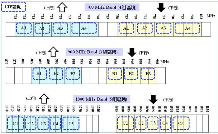
57 4G ( )(2013) 700 MHz 頻段 :(4 個區塊頻譜 ) ( )A1: 上 703~713MHz; 下 758~768MHz( 上下 各 10MHz) ( )A2: 上 713~723MHz; 下 768~778MHz( 上下 各 10MHz) ( 三 )A3: 上 723~733MHz; 下 778~788MHz( 上下 各 10MHz) ( 四 )A4: 上 733~748MHz; 下 788~803MHz( 上下 各 15MHz) 900MHz 頻段 :(3 個區塊頻譜 ) ( )B1: 上 885~895MHz; 下 930~940MHz( 上下 各 10MHz) ( )B2: 上 895~905MHz; 下 940~950MHz( 上下 各 10MHz) ( 三 )B3: 上 905~915MHz; 下 950~960MHz( 上下 各 10MHz) 三 1800 MHz 頻段 :(5 個區塊頻譜 ) ( )C1: 上 1710~1725MHz; 下 1805~1820MHz( 上下 各 15MHz) ( )C2: 上 1725~1735MHz; 下 1820~1830MHz( 上下 各 10MHz) ( 三 )C3: 上 1735~1745MHz; 下 1830~1840MHz( 上下 各 10MHz) ( 四 )C4: 上 1745~1755MHz; 下 1840~1850MHz( 上下 各 10MHz) ( 五 )C5: 上 1755~1770MHz; 下 1850~1865MHz( 上下 各 15MHz)
58
59

60 FDD Band7 TDD Band38 TDD Band41
61 Enhancements in Release 9 Multimedia Broadcast/Multicast Service (MBMS) Location services Dual layer beamforming Commercial mobile alert system
62 Multicast/Broadcast over a Single Frequency Network When delivering a broadcast or multicast service the radio access network transmits the same information stream from several nearby cells Multicast/broadcast over a single frequency network LTE exploits this feature to improve the transmission of broadcast and multicast services, using the technique of MBSFN
63 Using MBSFN nearby BSs - synchronized so that they broadcast the same content at the same time and on the same sub-carriers mobile - receives multiple copies of the information which are identical except for their different arrival times, amplitudes and phases - process the information streams using exactly the same techniques for handling multipath
64 Because the extra cells are transmitting the same information stream they do not cause any interference to the mobile instead, they contribute to the received signal power - this increases the mobile s SINR and maximum data rate, particularly at the edge of the cell where interference is usually high this allows LTE to reach a target spectral efficiency of 1 b/s/hz for the delivery of MBMS - equivalent to 16 mobile TV channels in a 5MHz bandwidth at a rate of 300 kbps each (= 5MHz / 16)
65 Architecture of MBMS Broadcast/Multicast Service Center (BM-SC) receives MBMS content from a content provider MBMS GateWay (MBMS-GW) distributes the content to the appropriate BSs Multicell/Multicast Coordination Entity (MCE) schedules the transmissions from all the BSs in a single MBSFN area Delivery of MBMS over LTE architecture
66 BM-SC (Broadcast/Multicast Service Center) indicates the start of each MBMS session by sending a signaling message across the SGmb interface the message describes the session s QoS and tells the MBMS GW to reserve resources for it the message is propagated across Sm, M3 and M2 interfaces M2 interface also defines - modulation scheme - coding rate - the subframe allocation that the BSs in the MBSFN area should use

67 BM-SC (Broadcast/Multicast Service Center) BM-SC then broadcasts the data across SGi-mb interface using IP multicast MBMS GW (MBMS GateWay) forwards data to the appropriate BSs across M1 interface, along with a header that indicates each packet s transmission time with an accuracy of 10 ms enb by combining the above info with the scheduling info that it receives from the multicell/multicast coordination entity, the BS can establish the exact transmission time for each packet
68 Location Services Location services (LCS) or Location Based Services (LBS), allow an application to find out the geographical location of a mobile The biggest motivation is emergency calls in USA, the FCC requires network operators to localize an emergency call to an accuracy between 50 and 300 meters, depending on the type of positioning technology used LCSs are also of increasing importance to the user, for applications such as navigation and interactive games Other applications include lawful interception by the police or security services use of a mobile s location to support network-based functions such as handover
69 Positioning Techniques LTE can calculate a mobile s position using three different techniques The most accurate and increasingly common technique is the use of a Global Navigation Satellite System (GNSS), a collective term for satellite navigation systems such as the Global Positioning System (GPS)
70 Global Navigation Satellite System (GNSS) two variants - UE based positioning the mobile has a complete satellite receiver and the mobile calculates its own position the network can send it information to assist this calculation, such as an initial position estimate and a list of visible satellites - UE assisted positioning the mobile has a more basic satellite receiver, so it sends a basic set of measurements to the network the network calculates its position positioning accuracy - typically around 10 meters

71 The second technique is downlink positioning or Observed Time Difference of Arrival (OTDOA) - the mobile measures the times at which signals arrive from its serving cell and the nearest neighbors reports the time differences to the network - the network calculate the mobile s position by triangulation - the timing measurements are made on a new set of positioning reference signals, which are transmitted on a new antenna port, number 6
72 - positioning accuracy limited by multipath typically to around 100 meters, has difficulty in meeting the requirements of US FCC - it is often used as a backup to satellite positioning, as a mobile may not be able to receive a satisfactory satellite signal if it is surrounded by tall buildings or is indoors
 of signals from the UE to provide directional information positioning accuracy - depends on the cell size - excellent in")
73 The last technique is Enhanced cell ID positioning (ECID) the network - estimates the mobile s position from its knowledge of the serving cell identity Round Trip Time (RTT), between the base station and the UE, to estimate the distance to the UE Angle of Arrival (AoA) of signals from the UE to provide directional information positioning accuracy - depends on the cell size - excellent in femtocells (provided that the BS s position is actually known) - very poor in macrocells ECID positioning
74 The figure shows the main hardware components that LTE uses for LCSs Gateway Mobile Location Center (GMLC) receives location requests from external clients across Le interface retrieves the identity of the mobile s serving MME from HSS forwards the location request to MME MME delegates responsibility for calculating a mobile s position to Evolved Serving Mobile Location Center (E-SMLC) Architecture for location services in LTE
75 Two other components can be separate devices or can be integrated into GMLC Privacy Profile Register (PPR) - contains the users privacy details, which determine whether a location request from an external client will actually be accepted Pseudonym [ 假名 ] Mediation [ 調節 ] Device (PMD) - retrieves a mobile s IMSI using the identity supplied by the external client
76 The architecture uses several signaling protocols GMLC communicates with HSS and MME - using Diameter applications MME communicates with E-SMLC - using LCS application protocol (LCS-AP) MME can also send positioning-related information to mobile EMM Diameter OSA - using supplementary service (SS) messages that are embedded into EMM messages on the air interface LCS-AP Diameter E-SMLC communicates with mobile and BS - using LTE positioning protocol (LPP), the messages being transported by embedding them into lower-level LCS-AP and EMM messages GMLC can communicate with external client - using a few different techniques, such as Open Service Architecture (OSA)

77 Dual Layer Beamforming In dual layer beamforming, the BS transmits two simultaneous data streams using the same set of resource blocks, by processing the data using two parallel sets of antenna weights It can then direct the data either to two different mobiles, or to two antennas on the same mobile
78 BS configures the mobile into a new transmission mode, mode 8, and schedules it using a new DCI format, 2B DCI Downlink Control Information
79 It then transmits to the mobile using either or both of two new antenna ports, numbers 7 and 8 Ports 7 and 8 use a new set of UE-specific reference signals, which behave in the same way as the reference signals used for single layer beamforming on port 5
80 Commercial Mobile Alert System US FCC established the Commercial Mobile Alert System (CMAS) in response to US Warning Alert and Response Network act of 2006 Using this system, participating network operators can transmit three types of emergency message presidential alerts about local, regional or national emergencies imminent [ 緊迫, 眉睫 ] threat alerts about natural disasters such as hurricanes child abduction emergency alerts
81 In Release 9, LTE supports CMAS by generalizing its earthquake and tsunami warning system to a Public Warning System (PWS) that covers both types of information BS continues to send earthquake and tsunami warnings on SIBs 10 and 11 transmits commercial mobile alerts on a new system information block, SIB 12
82 Enhancements in Release 10 (LTE-Advanced) Carrier Aggregation Enhancements to multiple antenna transmission on uplink and downlink Enhanced Downlink MIMO Enhanced Uplink MIMO Relays
83 Carrier Aggregation The ultimate goal of LTE-Advanced is to support a maximum bandwidth of 100 MHz It is most unlikely to be available as a contiguous allocation in the foreseeable future LTE-Advanced allows a mobile to transmit and receive on up to five component carriers (CC), each of which has a max bandwidth of 20 MHz using Carrier Aggregation (CA)
84
85
86 Three scenarios of Carrier Aggregation Inter-band aggregation - CCs are located in different frequency bands - this is the most challenging scenario, because mobile may require different radio components to support each band cell s coverage area in each band may be very different - the component carriers are separated by a multiple of 100 khz, which is the usual LTE carrier spacing
87 Contiguous intra-band aggregation CCs are in the same band and are adjacent to each other they are separated by a multiple of 300 khz, which is consistent with the orthogonality requirement, so that different sets of subcarriers are orthogonal to each other and do not interfere Non contiguous intra-band aggregation CCs are in the same band
88 Carrier aggregation only affects physical layer Media Access Control (MAC) protocol on the air interface RRC, S1-AP and X2-AP signaling protocols There is no impact on Radio link control (RLC) Packet Data Convergence Protocols (PDCP) data transport in the fixed network
89 Scheduling in Release 10, each CC independently scheduled generates an independent set of hybrid ARQ feedback bits (HARQ = FEC + ARQ) the system does, however, support cross carrier scheduling BS can trigger an uplink or downlink transmission on one CC using a scheduling message on another
90 Release 10 implements cross carrier scheduling by adding a Carrier Indicator Field (CIF) to each DCI format, which indicates the carrier to be used for the subsequent transmission Using cross carrier scheduling DCI Downlink Control Information BS can transmit its scheduling messages on the CC that has the greatest coverage, so as to maximize the reliability of successful reception it can also use technique to balance the loads from traffic and scheduling across different CCs
91 Data Transmission and Reception CA does not affect data transmission in the downlink, but it does lead to some changes in the uplink Release 8 a mobile uses SC-FDMA, which assumes that the mobile is transmitting on a single contiguous block of sub-carriers Release 10 this assumption is no longer valid the mobile uses a more general technique known as Discrete Fourier Transform Spread Orthogonal Frequency Division Multiple Access (DFT-S-OFDMA) DFT-S-OFDMA is the same as SC-FDMA, except that it supports transmission on a non contiguous allocation of sub-carriers
92 Enhanced Downlink MIMO Release 8 includes full support for downlink single user MIMO (SU-MIMO) using - max of four antenna ports - four transmission layers includes rudimentary support for downlink multiple user MIMO (MU-MIMO)
93 Release 9 introduces support for dual layer beamforming BS transmits to two receive antennas that are located on one or two mobiles Release 10 the dual layer beamforming technique is extended as part of release 10, by - providing full support for downlink MU-MIMO - increasing the max no. of BS antenna ports to eight the same technique can also be used to support SU-MIMO, with a max of eight antenna ports and eight transmission layers
94 The peak downlink data rate in Release 10 is 1200 Mbps this is four times greater than in Release 8 and results from the use of two CCs each CC carries eight transmission layers rather than four Eventually, LTE should support a peak downlink data rate of 3000 Mbps, through the use of five CCs
95 Enhanced Uplink MIMO The only multiple antenna scheme supported by Release 8 uplink is MU- MIMO This increases the cell capacity while only requiring the mobile to have a single transmit power amplifier and was far easier to implement than on the downlink In LTE-Advanced (Release 10), the uplink is enhanced to support SU- MIMO, using up to four transmit antennas and four transmission layers
96 Release 10 only supports SU-MIMO in TDD band 40 FDD bands 1, 3 and 7 The peak uplink data rate in Release 10 is 600 Mbps this is eight times greater than in Release 8, and results from the use of four transmission layers and two CCs Eventually, LTE should support a peak uplink data rate of 1500 Mbps, through the use of five CCs
97
98
99 Relays Repeaters and relays are devices that extend the coverage area of a cell They are useful in sparsely populated areas, in which the performance of a network is limited by coverage rather than capacity They can also increase the data rate at the edge of a cell, by improving the SINR there
100 Repeater a repeater receives a radio signal from the transmitter, and amplifies and rebroadcasts it, so appears to the receiver as an extra source of multipath unfortunately the repeater amplifies the incoming noise and interference as well as the received signal, which ultimately limits its performance FDD repeaters - fully specified in Release 8 - with sole specification referring to radio performance requirements TDD repeaters - harder to implement, because of the increased risk of interference between uplink and downlink - have not yet been specified
101 Relay decode the received radio signal, before reencoding and rebroadcasting it it removes the noise and interference from the retransmitted signal, so can achieve a higher performance than a repeater relays are first specified in Release 10, for both FDD and TDD modes
102 Relaying architecture the relaying functions are implemented in Relay Node (RN) this appears to mobile as a perfectly normal BS it has one or more physical cell IDs of its own broadcasts its own synchronization signals and system information responsible for scheduling all the uplink and downlink transmissions on the Uu interface
103 RN is controlled by a Donor enb (DeNB), which is otherwise a normal BS that can control mobiles of its own Un interface the air interface between RN and DeNB typically implemented as a point-to-point microwave link across this interface - DeNB acts like any other BS - RN acts like a mobile
104 Un and Uu interfaces can use either the same carrier frequency, or different ones If the carrier frequencies are different Un interface can be implemented in exactly the same way as a normal air interface e.g. - RN acts like a BS on the Uu interface towards mobile - RN independently acts like a mobile on the Un interface towards DeNB If the carrier frequencies are the same Un interface requires some extra functions to share the resources of the air interface with Uu
105 There is a variant of X2 interface between DeNB and RN supports handovers between RN and any other BS implemented in the same way as a normal X2 interface but transports data and signaling messages using the functions of the Un interface instead of IP A similar variant of S1 interface allows RN to communicate directly with MME and S-GW A new instance of S11 interface allows MME to configure the S1 tunneling functions inside the donor enb, by treating it in the same way as a S-GW
106 Restrictions on the use of relaying in Release 10 RNs are assumed to be stationary - a RN cannot be handed over from one DeNB to another multi-hop relaying is not supported - one RN cannot control another RN - no impact on the mobile, which is completely unaware that it is being controlled by a relay - this implies that Release 8 mobiles support relaying in just the same way as Release 10 mobiles
107 Enhancements in Release 11 Coordinated Multipoint Transmission and Reception Enhanced Carrier Aggregation
108 Coordinated Multipoint Transmission and Reception (CoMP) CoMP is a wide-ranging term, which refers to any type of coordination between the radio communications that are taking place in nearby cells its aim is to increase the data rate at the cell edge and the overall throughput of the cell
109 Two main varieties from the viewpoint of downlink (similar issues apply on the uplink) Coordinated Scheduling and Beamforming (CS/CB) - a mobile receives data from one cell at a time, its serving cell - however, the serving cell can coordinate its scheduling and beamforming processes with those of cells nearby, so as to minimize the inter-cell interference - e.g., a cell can configure its beamforming pattern on the subcarriers that a mobile in a neighboring cell is using
110 Joint Processing (JP) - a mobile receives data from multiple cells - these cells can be controlled by one BS, which is not too hard to implement - alternatively, the cells can be controlled by multiple BSs, which offers better performance but makes issues such as backhaul and synchronization far harder
111 The cells used for joint processing can transmit the same data stream as each other, in which case they are operating as diversity transmitters (the same technique is used for soft handover in UMTS) Alternatively, they can transmit different data streams, in an implementation of spatial multiplexing that is known as cooperative MIMO (shown in the figure) this has some similarities with MU-MIMO, but instead of separating the mobile antennas onto two different devices, we separate the network s antennas onto two different cells
112 Enhanced Carrier Aggregation CA will also be enhanced in forthcoming releases of LTE Three main aspects aggregation using more CCs and resource blocks, so as to increase the mobile s peak data rate aggregation in more FDD and TDD bands allow mobile to use multiple values of the uplink timing advance, one for each CC - this is helpful when CA is used in conjunction with relaying, as it allows the mobile to send one uplink CC to a DeNB another with a different timing advance to a RN
System Architecture Evolution
 System Architecture Evolution Contents 2.1 Architecture of LTE 2.2 Communication Protocols 2.3 Example Information Flows 2.4 Bearer Management 2.5 State Diagrams 2.6 Spectrum Allocation 2.1 Architecture
INTRODUCTION TO LTE. ECE MOBILE COMMUNICATION Monday, 25 June 2018
 INTRODUCTION TO LTE ECE 2526 - MOBILE COMMUNICATION Monday, 25 June 2018 1 WHAT IS LTE? 1. LTE stands for Long Term Evolution and it was started as a project in 2004 by the Third Generation Partnership
DAY 2. HSPA Systems Architecture and Protocols
 DAY 2 HSPA Systems Architecture and Protocols 1 LTE Basic Reference Model UE: User Equipment S-GW: Serving Gateway P-GW: PDN Gateway MME : Mobility Management Entity enb: evolved Node B HSS: Home Subscriber
LTE Rel-9 9 and LTE-Advanced in 3GPP
 LTE Rel-9 9 and LTE-Advanced in 3GPP May 19, 2009 Takehiro Nakamura 3GPP TSG-RAN chairman NTT DOCOMO, INC. May 19, 2009 Copyright 2008 NTT DOCOMO, Inc. All rights reserved 1 Introduction In 3GPP Rel-8
1.1 Beyond 3G systems
 1 Introduction The cellular wireless communications industry witnessed tremendous growth in the past decade with over four billion wireless subscribers worldwide. The first generation (1G) analog cellular
POWER-ON AND POWER-OFF PROCEDURES
 POWER-ON AND POWER-OFF PROCEDURES TABLE OF CONTENTS 1. Power-On Sequence 2. Network and Cell Selection 3. RRC Connection Establishment 4. Attach Procedure 5. Detach Procedure 1. POWER-ON SEQUENCE The following
LTE-Advanced Relay. Oct 18, 2011
 LTE-Advanced Relay Oct 18, 2011 LTE/LTE-A Overview 3GPP Rel-10 Relay LTE-A Relay 3GPP Rel-11 Relay 2 LTE/LTE-A Overview 3GPP Rel-10 Relay LTE-A Relay 3GPP Rel-11 Relay 3 Cellular Roadmap Spectrum Efficiency
Mobile Network Evolution Part 2
 Mobile Network Evolution Part 2 From UMTS to LTE or How to Further Increase Network Capacity and QoS Andreas Mitschele-Thiel Advanced Mobile Communication Networks 1 Outline Evolution from Circuit Switching
GPRS and UMTS T
 GPRS and UMTS T-110.2100 Global Packet Radio Service GPRS uses the time slots not used for circuit switched services Data rate depends on the availability of free time slots GPRS uses the multislot technique,
Delivery of Voice and Text Messages over LTE 13 年 5 月 27 日星期 一
 Delivery of Voice and Text Messages over LTE 1. The Market for Voice and SMS 2. Third Party Voice over IP 3. The IP Multimedia Subsystem 4. Circuit Switched Fallback 5. VoLGA LTE was designed as a data
LTE Radio Interface Architecture. Sherif A. Elgohari
 LTE Radio Interface Architecture Sherif A. Elgohari (selgohari@ieee.org) Agenda Overall System Architecture Radio Protocol Architecture Radio Link Control Medium Access Control Physical Layer Control Plan
Simulation of LTE Signaling
 Simulation of LTE Signaling 1 Florin SANDU, 2 Szilárd CSEREY, 3 Eugen MILE-CIOBANU 1 "Transilvania University of Brasov Bd Eroilor nr. 29A RO-500036 Brasov sandu@unitbv.ro, 2,3 SIEMENS Program and System
WCDMA evolution: HSPA and MBMS
 Chapter: 3G Evolution 8 WCDMA evolution: HSPA and MBMS Isael Diaz isael.diaz@eit.lth.se Department of Electrical and Information Technology 02-Apr-2009 3G Evolution - HSPA and LTE for Mobile Broadband
Introduction to Mobile Broadband (imb)
") Introduction to Mobile Broadband (imb) Teaching By Asst.Prof.Dr. Suwat Pattaramalai suwat.pat@kmutt.ac.th Tel. 02-470-9079 Material: http://webstaff.kmutt.ac.th/~suwat.pat/ 3GPP WiMAX FORUM Introduction
Introduction to Mobile Broadband (imb) Teaching By Asst.Prof.Dr. Suwat Pattaramalai suwat.pat@kmutt.ac.th Tel. 02-470-9079 Material: http://webstaff.kmutt.ac.th/~suwat.pat/ 3GPP WiMAX FORUM Introduction
Quality of Service, Policy and Charging
 Quality of Service, Policy and Charging Contents 1. Policy and Charging Control! 2. Session Management Procedures! 3. Charging and Billing 1. Policy and Charging Control 1.1 Introduction! 1.2 Quality of
Long Term Evolution - Evolved Packet Core S1 Interface Conformance Test Plan
 Long Term Evolution - Evolved Packet Core S1 Interface Conformance Test Plan Table of Contents 1 SCOPE... 10 2 REFERENCES... 10 3 ABBREVIATIONS... 11 4 OVERVIEW... 14 5 TEST CONFIGURATION... 16 5.1 NETWORK
4G LTE Technologies: System Concepts
 4G LTE Technologies: System Concepts CK Toh, PhD, Chief Technology Advisor, ALICO Systems Inc., Torrance, CA, US ABSTRACT Recently, we have witnessed the roll out of LTE (Long Term Evolution, or so called
UMTS System Architecture and Protocol Architecture
 UMTS System Architecture and Protocol Architecture Overview on overall system architecture UMTS network architecture and elements Mobile station High-level functions UMTS domains and strata UMTS/GPRS protocol
Primebit Solution EXPERT DIPLOMA IN PROTOCOL TESTING COURSE CONTENT
 EXPERT DIPLOMA IN PROTOCOL TESTING COURSE CONTENT MODULE 1 : UMTS (3G) AND GSM (2G) BASIC 2G and 3G Network Architecture - CS & PS domain. RAT- FDMA, TDMA, CDMA, WCDMA, DFDMA, SCFDMA. SDU,PDU,UMTS N/W
Abstract of the Book
 Book Keywords IEEE 802.16, IEEE 802.16m, mobile WiMAX, 4G, IMT-Advanced, 3GPP LTE, 3GPP LTE-Advanced, Broadband Wireless, Wireless Communications, Cellular Systems, Network Architecture Abstract of the
Mobile Broadband Communications
 Mobile Broadband Communications (WiMAX & LTE) Teaching By Asst.Prof.Dr. Suwat Pattaramalai suwat.pat@kmutt.ac.th Tel. 02-470-9079 3GPP WiMAX FORUM Mobile Broadband Communications Contents Part I Fundamentals
Telecom Learning. Technology
 Telecom Learning Technology LTE Modules S. No. LTE Module Course Content LTE Overview LTE /EPS Network Architecture 1 LTE Basics LTE/EPS Mobility & Session Mgmt LTE Air Interface LTE Air Interface LTE-RF
ENG Advanced Mobile Networks: QoS, QoE & Technical Aspects
 ENG-514 - Advanced Mobile Networks: QoS, QoE & Technical Aspects Description The increasing uptake of Internet of Things (IoT), Big data and cloud-based services introduces a new set of requirements for
4G LTE MOBILE TOWER TRANSMITTER RECEIVER REAL SYSTEM TRAINER MODEL - 4GLTE100
 4G LTE MOBILE TOWER TRANSMITTER RECEIVER REAL SYSTEM TRAINER MODEL - 4GLTE100 This trainer has been designed with a view to provide practical and experimental knowledge of 4G LTE Realtime Mobile Transmitter
A Review on Soft Handover Schemes in LTE Cellular Networks
 http:// A Review on Soft Handover Schemes in LTE Cellular Networks Shreedhar K V M Department of Computer Science and Engineering R V College of Engineering Bengaluru, India - 560095 Abstract - Long Term
Novel design of embms based on Femtocell
 Novel design of embms based on Femtocell Otgonbayar Bataa a, Young-il Kim b, Erdenetuya Dorj c, Bat-Enkh Oyunbileg d, Khishigjargal Gonchigsumlaa e, Oyu Chuluun f, Tulga Orosoo g a, f, g Wireless Communication
3GPP. 3GPP Roadmap. Release 99 Release 4 Release 5 Release 6 Release 7 Release 8. Khaled Alutaibi
 3GPP Release 99 Release 4 Release 5 Release 6 Release 7 Release 8 Khaled Alutaibi LOGO 976452 3GPP Roadmap Radio Access Air Interface Principles Release99 The main improvement of UMTS compared to GSM in
LTE Training LTE (Long Term Evolution) Training Bootcamp, Crash Course
 Training Bootcamp, Crash Course") LTE Training LTE (Long Term Evolution) Training Bootcamp, Crash Course Why should you choose LTE Training? LTE Training is an intensive learning experience that cover the essential elements of Long Term
LTE Training LTE (Long Term Evolution) Training Bootcamp, Crash Course Why should you choose LTE Training? LTE Training is an intensive learning experience that cover the essential elements of Long Term
Primebit Solution MASTERED DIPLOMA IN PROTOCOL DEVELOPMENT COURSE CONTENT
 MASTERED DIPLOMA IN PROTOCOL DEVELOPMENT COURSE CONTENT MODULE 1 : UMTS (3G) AND GSM (2G) BASIC 2G and 3G Network Architecture - CS & PS domain. RAT- FDMA, TDMA, CDMA, WCDMA, DFDMA, SCFDMA. SDU,PDU,UMTS
Delivery of Voice and Text Messages over LTE
 Delivery of Voice and Text Messages over LTE 1. The Market for Voice and SMS 2. Third Party Voice over IP 3. The IP Multimedia Subsystem 4. Circuit Switched Fallback 5. VoLGA Two main approaches to the
Overview of WiMAX (Chapter 2) ENE 490 MON 13:30-16:30 Asst. Prof. Suwat Pattaramalai
 ENE 490 MON 13:30-16:30 Asst. Prof. Suwat Pattaramalai") (Chapter 2) ENE 490 MON 13:30-16:30 Asst. Prof. Suwat Pattaramalai Background on IEEE 802.16 and WiMAX (Table 2.1 and Table 2.2) Salient Features of WiMAX OFDM-based physical layer: good resistance to
(Chapter 2) ENE 490 MON 13:30-16:30 Asst. Prof. Suwat Pattaramalai Background on IEEE 802.16 and WiMAX (Table 2.1 and Table 2.2) Salient Features of WiMAX OFDM-based physical layer: good resistance to
NETWORK DIAGNOSTICS Testing HSDPA, HSUPA for 3G mobile apps
 NETWORK DIAGNOSTICS Testing HSDPA, HSUPA for 3G mobile apps By Simon Binar Protocol Monitoring Division Tektronix Inc. The market for broadband cellular data services is rapidly evolving. From its deployment
Architecture and Protocols of EPC-LTE with relay
 Architecture and Protocols of EPC-LTE with relay Yangyang Chen, Xavier Lagrange To cite this version: Yangyang Chen, Xavier Lagrange. Architecture and Protocols of EPC-LTE with relay. 13360. 2013, pp.25.
Original Circular Letter
 LTE-Advanced Original Circular Letter LTE-Advanced will be an evolution of LTE. Therefore LTE- Advanced must be backward compatible with LTE Release 8. LTE-Advanced requirements will meet or even exceed
New format LTE guide-v7_layout 1 10/01/ :33 Page 1. Understanding LTE.
 New format LTE guide-v7_layout 1 10/01/2013 10:33 Page 1 Understanding LTE www.anritsu.com New format LTE guide-v7_layout 1 10/01/2013 10:33 Page 1 Table of Contents Definition of FMC... 2 FMC motivations...
RADIO PROTOCOLS FOR LTE AND LTE-ADVANCED
 RADIO PROTOCOLS FOR LTE AND LTE-ADVANCED Seungjune Yi SungDuck Chun YoungDae Lee Sungjun Park SungHoon Jung LG Electronics, South Korea WILEY Foreword by Takehiro Nakamura Preface About the Authors 1 Introduction
ETSI TS V ( )
") TS 123 285 V14.2.0 (2017-05) TECHNICAL SPECIFICATION Universal Mobile Telecommunications System (UMTS); LTE; Architecture enhancements for V2X services (3GPP TS 23.285 version 14.2.0 Release 14) 1 TS 123
TS 123 285 V14.2.0 (2017-05) TECHNICAL SPECIFICATION Universal Mobile Telecommunications System (UMTS); LTE; Architecture enhancements for V2X services (3GPP TS 23.285 version 14.2.0 Release 14) 1 TS 123
Rab Nawaz Jadoon. Cellular Systems - II DCS. Assistant Professor. Department of Computer Science. COMSATS Institute of Information Technology
 Cellular Systems - II Rab Nawaz Jadoon DCS Assistant Professor COMSATS IIT, Abbottabad Pakistan COMSATS Institute of Information Technology Mobile Communication UMTS Architecture A UMTS network consist
Development of MD8430A for LTE-Advanced Tests
 Masaki Hizume, Hidenori Konno, Toshiro Miyazaki, Masato Sasaki, Katsuo Sakurai, Satoshi Wakasa, Shinichi Segawa, Tomoyuki Fujiwara, Yuji Sakai [Summary] As part of the expansion of LTE (Long Term Evolution)
awaves academy EPS/LTE Training Program In cooperation with GreenlightPM and TheSpecTool TheSpecTool
 awaves academy EPS/LTE Training Program In cooperation with GreenlightPM and TheSpecTool 2011-2012 awaves academy www.awaves.com TheSpecTool www.thespectool.com Greenlight Project Management S.L. www.greenlightpm.com
Key Performance Aspects of an LTE FDD based Smart Grid Communications Network
 Key Performance Aspects of an LTE FDD based Smart Grid Communications Network Presented by: Ran Zhang Supervisors: Prof. Sherman(Xuemin) Shen, Prof. Liang-liang Xie Main Reference Jason Brown, and Jamil
Buletinul Ştiinţific al Universităţii "Politehnica" din Timişoara. Seria ELECTRONICĂ şi TELECOMUNICAŢII TRANSACTIONS on ELECTRONICS and COMMUNICATIONS
 Buletinul Ştiinţific al Universităţii "Politehnica" din Timişoara Seria ELECTRONICĂ şi TELECOMUNICAŢII TRANSACTIONS on ELECTRONICS and COMMUNICATIONS Tom 58(72), Fascicola 2, 2013 Mobility in LTE Alexandra
A Flow Label Based QoS Scheme for End-to-End Mobile Services
 A Flow Label Based QoS Scheme for End-to-End Mobile Services Tao Zheng, Lan Wang, Daqing Gu Orange Labs Beijing France Telecom Group Beijing, China e-mail: {tao.zheng; lan.wang; daqing.gu}@orange.com Abstract
Hands-On Modern Mobile and Long Term Evolution LTE
 Hands-On LTE Course Description With 3G mobile technologies already rolled out by over 200 operators in over 80 countries, standards bodies, manufacturers and operators are looking towards the next generation
T Computer Networks II Mobile networks
 T-110.5111 Computer Networks II Mobile networks 03.11.2014 Matti Siekkinen Sources: J. Kurose, K. Ross. Computer Networking: A Top Down Approach. 6 th edition, Addison-Wesley, April 2009. A. Larmo et al:
Third generation WCDMA radio evolution
 WIRELESS COMMUNICATIONS AND MOBILE COMPUTING Wirel. Commun. Mob. Comput. 2003; 3:987 992 (DOI: 10.1002/wcm.134) Third generation WCDMA radio evolution Harri Holma*,y and Antti Toskala Nokia Networks, IP
AL-FEC for Streaming Services over LTE Systems
 AL-FEC for Streaming Services over LTE Systems Christos Bouras 1,2, Nikolaos Kanakis 2, Vasileios Kokkinos 1,2, Andreas Papazois 1,2 1 Computer Technology Institute and Press Diophantus, Patras, Greece
3GPP TS V ( )
") Technical Specification 3rd Generation Partnership Project; Technical Specification Group Radio Access Network; Evolved Universal Terrestrial Radio Access Network (E-UTRAN); General aspects and principles
Technical Specification 3rd Generation Partnership Project; Technical Specification Group Radio Access Network; Evolved Universal Terrestrial Radio Access Network (E-UTRAN); General aspects and principles
UNIK4230: Mobile Communications Spring Semester, Per Hj. Lehne
 UNIK4230: Mobile Communications Spring Semester, 2015 Per Hj. Lehne per-hjalmar.lehne@telenor.com 916 94 909 Network Architecture and Functionality 5 February 2015 Contents Network Architecture Protocol
Long Term Evolution - LTE L10 Training Programs. Catalog of Course Descriptions
 Long Term Evolution - LTE L10 Training Programs Catalog of Course Descriptions Page 2 Catalog of Course Descriptions INTRODUCTION... 3 LTE EVOLUTION, ADVANTAGES IN FEATURES AND APPLICATIONS... 4 LTE/SAE
New service standardisation approach
 UMTS Part of the IMT 2000 family 3 nd Generation digital cellular mobile system Approximately old (GSM + GPRS) core network + new radio access network (UTRAN) including new radio interface (WCDMA) New
Mobile Network Evolution Part 2
 Mobile Network Evolution Part 2 From UMTS to LTE or How to Further Increase Network Capacity and QoS Andreas Mitschele-Thiel Advanced Mobile Communication Networks 1 Outline Evolution from Circuit Switching
2. enodeb Emulator: Simulation of emtc and NB-IoT UE and enodeb conforming to 3GPP Release 13 enhancements for Cellular IoT.
 Version 13.0.0.2 Release Date: Feb 17, 2017 NetTest v13.0 Release Notes Page 1 of 12 1. C-SGN Emulator: Includes the MME, SGW and PGW Emulators with new interfaces and functions for testing CIoT base stations
Cross Layer Design for Efficient Video Streaming over LTE Using Scalable Video Coding
 Cross Layer Design for Efficient Video Streaming over LTE Using Scalable Video Coding Rakesh Radhakrishnan, Balaaji Tirouvengadam, Amiya Nayak School of Electrical Engineering and Computer Science, University
awaves academy EPS/LTE Training Program In cooperation with GreenlightPM and TheSpecTool awaves academy
 awaves academy EPS/LTE Training Program In cooperation with GreenlightPM and TheSpecTool 2011-2013 awaves academy www.awaves.com TheSpecTool www.thespectool.com Greenlight Project Management S.L. www.greenlightpm.com
Wireless Communication
 Wireless Communication Hwajung Lee Key Reference: Prof. Jong-Moon Chung s Lecture Notes at Yonsei University Wireless Communications Bluetooth Wi-Fi Mobile Communications LTE LTE-Advanced Mobile Communications
Wireless Networking: An Introduction. Hongwei Zhang
 Wireless Networking: An Introduction Hongwei Zhang http://www.cs.wayne.edu/~hzhang Outline Networking as resource allocation A taxonomy of current practice Technical elements Outline Networking as resource
Nr. Standard reference Title
 Nr. Standard reference Title 1 2 ETSI EN 300 392-12-22 V1.4.1 ETSI TS 124 229 V8.30.0 Terrestrial Trunked Radio (TETRA); Voice plus Data (V+D); Part 12: Supplementary services stage 3; Sub-part 22: Dynamic
LTE EPC Emulators v10.0 Release Notes - Page 1 of 15 -
 LTE EPC Emulators v10.0 Release Notes - Page 1 of 15 - Version 10.0.0.7 Release Date: Feb 24, 2014 Components 1. LTE Emulators : MME (with internal HSS), SGW and PGW (with internal PCRF) 1. LTE Emulators
COMP327 Mobile Computing Session: Lecture Set 5 - Wireless Communication Part 2
 COMP327 Mobile Computing Session: 2016-2017 Lecture Set 5 - Wireless Communication Part 2 51 SIM (Subscriber Identity Modules) Smart cards that are inserted into the GSM phone to identify the user Stores
Authentication of 4G LTE-Advanced System Model
 Authentication of 4G LTE-Advanced System Model Ghassan A. Abed Abstract LTE-Advanced was accomplished in late of 2010 and it enhanced the LTE spectrum flexibility over carrier aggregation, further its
Dimensioning, configuration and deployment of Radio Access Networks. part 1: General considerations. Mobile Telephony Networks
 Dimensioning, configuration and deployment of Radio Access Networks. part 1: General considerations Mobile Telephony Networks 1 The Evolution of Mobile Telephony 1st Generation 2nd 3rd 4th Analogue Voice
LTE: MIMO Techniques in 3GPP-LTE
 Nov 5, 2008 LTE: MIMO Techniques in 3GPP-LTE PM101 Dr Jayesh Kotecha R&D, Cellular Products Group Freescale Semiconductor Proprietary Information Freescale and the Freescale logo are trademarks of Freescale
IxLoad LTE Evolved Packet Core Network Testing: enodeb simulation on the S1-MME and S1-U interfaces
 IxLoad LTE Evolved Packet Core Network Testing: enodeb simulation on the S1-MME and S1-U interfaces IxLoad is a full-featured layer 4-7 test application that provides realworld traffic emulation testing
HSPA+ R8. February 2009
 HSPA+ R8 February 2009 Disclaimer Nothing in this presentation is an offer to sell any of the parts referenced herein. This presentation may reference and/or show images of parts and/or devices utilizing
T325 Summary T305 T325 B BLOCK 2 4 PART III T325. Session 1 Block III Part 2 Section 2 - Continous Network Architecture. Dr. Saatchi, Seyed Mohsen
 T305 T325 B BLOCK 2 4 PART III T325 Summary Session 1 Block III Part 2 Section 2 - Continous Network Architecture [Type Dr. Saatchi, your address] Seyed Mohsen [Type your phone number] [Type your e-mail
Communication Systems for the Mobile Information Society
 Communication Systems for the Mobile Information Society Martin Sauter Nortel Networks, Germany John Wiley Si Sons, Ltd Contents Preface List of Figures List of Tables List of Abbreviations xi xiii xix
The Open-Source SDR LTE Platform for First Responders. Software Radio Systems
 The Open-Source SDR LTE Platform for First Responders Software Radio Systems www.softwareradiosystems.com www.github.com/srslte Outline SRS - Software Radio Systems NIST PSIAP and OpenFirst srslte The
Analysis of a Multiple Content Variant Extension of the Multimedia Broadcast/Multicast Service
 PUBLISHED IN: PROCEEDINGS OF THE EUROPEAN WIRELESS 2006 CONFERENCE 1 Analysis of a Multiple Content Variant Extension of the Multimedia Broadcast/Multicast Service George Xylomenos, Konstantinos Katsaros
ENERGY EFFICIENT VIDEO TRANSMISSION USING COOPERATION OF LTE AND WLAN
 ENERGY EFFICIENT VIDEO TRANSMISSION USING COOPERATION OF LTE AND WLAN by Maryam Hamidirad B.Eng., Sharif University of Technology, 2009 A THESIS SUBMITTED IN PARTIAL FULFILLMENT OF THE REQUIREMENTS FOR
LTE Networks: Benchmarks, Prospects and Deployment Limitation
 , July 2-4, 2014, London, U.K. LTE Networks: Benchmarks, Prospects and Deployment Limitation O.O. Oni, A.A.A. Atayero, F.E. Idachaba, A.S. Alatishe, Members, IAENG Abstract High speed packet access (HSPA)
3GPP TS V ( )
") TS 23.303 V12.7.0 (2015-12) Technical Specification 3rd Generation Partnership Project; Technical Specification Group Services and System Aspects; Proximity-based services (); Stage 2 (Release 12) The
TS 23.303 V12.7.0 (2015-12) Technical Specification 3rd Generation Partnership Project; Technical Specification Group Services and System Aspects; Proximity-based services (); Stage 2 (Release 12) The
HSPA+ Advanced Smart Networks: Multipoint Transmission
 Qualcomm Incorporated February 2011 Table of Contents 1. Introduction... 1 2. Multipoint HSPA Description... 2 Single Frequency Multipoint HSPA... 2 Dual Frequency Multipoint HSPA... 3 3. Advantages...
3GPP TS V ( )
") TS 36.443 V11.3.0 (2013-06) Technical Specification 3 rd Generation Partnership Project; Technical Specification Group Radio Access Network; Evolved Universal Terrestrial Radio Access Network (E-UTRAN);
TS 36.443 V11.3.0 (2013-06) Technical Specification 3 rd Generation Partnership Project; Technical Specification Group Radio Access Network; Evolved Universal Terrestrial Radio Access Network (E-UTRAN);
5G: an IP Engineer Perspective
 5G: an Engineer Perspective Igor Giangrossi Principal Consulting Engineer /Optical Networks igor.giangrossi@nokia.com 1 NANOG 75 A Brief History of Mobile Networks From analog voice to high speed Internet
Keywords Quality of Service (QoS), Long Term Evolution (LTE), System Architecture Evolution (SAE), Evolved Packet System (EPS).
, Long Term Evolution (LTE), System Architecture Evolution (SAE), Evolved Packet System (EPS).") Volume 5, Issue 7, July 2015 ISSN: 2277 128X International Journal of Advanced Research in Computer Science and Software Engineering Research Paper Available online at: www.ijarcsse.com A Review of 3GPP-LTE
Volume 5, Issue 7, July 2015 ISSN: 2277 128X International Journal of Advanced Research in Computer Science and Software Engineering Research Paper Available online at: www.ijarcsse.com A Review of 3GPP-LTE
4G Mobile Communications
 4G Mobile Communications Welcome to 4G The term 4G is used broadly to include several types of broadband wireless access communication systems, not only cellular telephone systems. One of the terms to
TIMING; The Key To Unlocking The Benefits Of LTE-A Timing & Security Considerations for Evolved IP Backhaul
 TIMING; The Key To Unlocking The Benefits Of LTE-A Timing & Security Considerations for Evolved IP Backhaul Ian Goetz, Juniper Networks November, 2016 Market Trends & The Network Environment Mobile Market
LTE Relay Node Self-Configuration
 12th IFIP/IEEE IM 2011: Application Session IM 2011 Application Session LTE Relay Node Self-Configuration Péter Szilágyi, Henning Sanneck Nokia Siemens Networks Research 1 Nokia Siemens Networks LTE Relay
Evaluation of 3GPP LTE and IEEE as Candidate IMT-Advanced Systems
 Mobility Evaluation of 3GPP LTE and IEEE 802.16 as Candidate IMT-Advanced Systems Ryan van den Bergh & Prof. H. Hanrahan School of Electrical and Information Engineering, University of the Witwatersrand
Communication and Distributed Systems Seminar on : LTE Security. By Anukriti Shrimal May 09, 2016
 Communication and Distributed Systems Seminar on : LTE Security By Anukriti Shrimal May 09, 2016 LTE network with interfaces LTE Security 2 Contents LTE Security : Why, What, How EPS Architecture Design
On the road with 3GPP. 3GPP s Long Term Evolution and System Architecture Evolution projects
 On the road with 3GPP 3GPP s Long Term Evolution and System Architecture Evolution projects 1 3GPP Evolution LTE AND SAE Francois COURAU TSG RAN Chairman 2 What 3GPP is A collaborative agreement between
Mobile Broadband Comparison. CDMA Development Group March 2008
 Mobile Broadband Comparison CDMA Development Group March 2008 Assumptions and Notes for the Technology Comparison This document compares the performance of existing and future mobile communications systems
Addressing Current and Future Wireless Demand
 Addressing Current and Future Wireless Demand Dave Wolter Executive Director Radio Technology AT&T Architecture and Planning Rising Demand and The Need to Innovate in the Network 6,732% growth over 13
Wireless# Guide to Wireless Communications. Objectives
 Wireless# Guide to Wireless Communications Chapter 8 High-Speed WLANs and WLAN Security Objectives Describe how IEEE 802.11a networks function and how they differ from 802.11 networks Outline how 802.11g
Understanding LTE - Long Term Evolution - in Depth The Next Step in Mobile Evolution in Detail
 Understanding The Next Step in Mobile Evolution in Detail Course Description With 3G mobile technology already rolled out by over 200 operators in over 80 countries, preparations are well under way to
ETSI TS V ( )
") TS 123 246 V14.1.0 (2017-05) TECHNICAL SPECIFICATION Universal Mobile Telecommunications System (UMTS); LTE; Multimedia Broadcast/Multicast Service (MBMS); Architecture and functional description (3GPP
TS 123 246 V14.1.0 (2017-05) TECHNICAL SPECIFICATION Universal Mobile Telecommunications System (UMTS); LTE; Multimedia Broadcast/Multicast Service (MBMS); Architecture and functional description (3GPP
E1-E2 UPGRADATION COURSE CONSUMER MOBILITY. 3G Concept
 E1-E2 UPGRADATION COURSE CONSUMER MOBILITY 3G Concept Page 1 CHAPTER-TWO 3 G CONCEPT UMTS and the information society Rapid advancements in Information and Communications Technology (ICT) have already
SON/RRM Functionality for Mobility Load Balancing in LTE Networks
 SON/RRM Functionality for Mobility Load Balancing in LTE Networks Salvador Navarro Suria E.T.S.I. Telecomunicaciones Universidad Politécnica de Valencia A thesis sumitted for the degree of Master in Telecommunications
IT Certification Exams Provider! Weofferfreeupdateserviceforoneyear! h ps://www.certqueen.com
 IT Certification Exams Provider! Weofferfreeupdateserviceforoneyear! h ps://www.certqueen.com Exam : 4A0-M02 Title : Alcatel-Lucent Mobile Gateways for the LTE Evolved Packet Core Version : Demo 1 / 7
ETSI TS V ( )
") TS 23 007 V4.4.0 (208-0) TECHNICAL SPECIFICATION Digital cellular telecommunications system (Phase 2+) (GSM); Universal Mobile Telecommunications System (UMTS); LTE; Restoration procedures (3GPP TS 23.007
TS 23 007 V4.4.0 (208-0) TECHNICAL SPECIFICATION Digital cellular telecommunications system (Phase 2+) (GSM); Universal Mobile Telecommunications System (UMTS); LTE; Restoration procedures (3GPP TS 23.007
Requirement Plan Plan Name: LTE_Data_Retry Plan Id: LTEDATARETRY Version Number: 31 Release Date: June 2018
 Requirement Plan Requirement Plan Plan Name: Plan Id: LTEDATARETRY Version Number: 31 Release Date: June 2018 This document provides initial information related to Verizon Wireless Long Term Evolution
Signaling Protocol Structure in GSM
 GSM Signaling Protocol Structure in GSM Signaling Protocol Structure in GSM Layer 1 is the physical layer which uses the channel structures over the air interface. Layer 2 is the data link layer and across
Virtual Evolved Packet Core (VEPC) Placement in the Metro Core- Backhual-Aggregation Ring BY ABHISHEK GUPTA FRIDAY GROUP MEETING OCTOBER 20, 2017
 Placement in the Metro Core- Backhual-Aggregation Ring BY ABHISHEK GUPTA FRIDAY GROUP MEETING OCTOBER 20, 2017") Virtual Evolved Packet Core (VEPC) Placement in the Metro Core- Backhual-Aggregation Ring BY ABHISHEK GUPTA FRIDAY GROUP MEETING OCTOBER 20, 2017 LTE: All-IP, simplified network architecture [1] Introduction
Virtual Evolved Packet Core (VEPC) Placement in the Metro Core- Backhual-Aggregation Ring BY ABHISHEK GUPTA FRIDAY GROUP MEETING OCTOBER 20, 2017 LTE: All-IP, simplified network architecture [1] Introduction
Wireless Communication
 Wireless Communication Hwajung Lee Key Reference: Prof. Jong-Moon Chung s Lecture Notes at Yonsei University Wireless Communications Bluetooth Wi-Fi Mobile Communications LTE LTE-Advanced Mobile Communications
3GPP TS V9.4.0 ( )
") TS 23.007 V9.4.0 (2010-06) Technical Specification 3rd Generation Partnership Project; Technical Specification Group Core Network and Terminals; Restoration procedures (Release 9) The present document
TS 23.007 V9.4.0 (2010-06) Technical Specification 3rd Generation Partnership Project; Technical Specification Group Core Network and Terminals; Restoration procedures (Release 9) The present document
Version LTE Emulators v10.2 Release Notes - Page 1 of 16 - Release Date: Aug 28, Resolved Issues
 Version 10.2.0.15 Release Date: Aug 28, 2015 Resolved Issues LTE Emulators v10.2 Release Notes - Page 1 of 16-11336 MME does not release previous S1 association when UE Context Release Request procedure
IPv6 in Mobile Networks and IMS Ericsson NEA Toshikane Oda
 IPv6 in Mobile Networks and IMS 2009-02-25 Ericsson NEA Toshikane Oda Outline 1. Growth of Mobile Broadband Markets 2. Evolution of Mobile Packet System 3. IMS for Converged IP Multimedia Services 4. EU
embms application tests with the R&S CMW 500 and R&S CMWcards
 embms application tests with the R&S CMW 500 and R&S CMWcards Fig. 1: The R&S CMW500 is the first test instrument in the world to boast an integrated BM-SC service layer, with the result that it can be
ETSI TS V ( )
") Technical Specification LTE; Evolved Universal Terrestrial Radio Access Network (E-UTRAN); General aspects and principles for interfaces supporting Multimedia Broadcast Multicast Service (MBMS) within
Technical Specification LTE; Evolved Universal Terrestrial Radio Access Network (E-UTRAN); General aspects and principles for interfaces supporting Multimedia Broadcast Multicast Service (MBMS) within