TC-9102 Series Surface Mount Temperature Controllers
|
|
|
- Gwenda Daniels
- 5 years ago
- Views:
Transcription


 models accept 120 to 240VAC. Relay(s) Contact Rating: 1 relay on single stage models, 2 relays on dual stage models.")

1 TC-9102 Series Surface Mount Temperature Controllers General Description & Applications The TC-9102 Series Temperature Controller offers a versatile solution for a wide variety of applications that may require 30 amp relays, short cycle delays and independent dual stages in one convenient, easy to use controller. The TC-9102 controller can accommodate input voltages from 12VAC to 240VAC. The TC-9102 comes with a temperature sensor with a temperature range of -40 to 300F (-40 to 148 C). An optional RTD sensor is also available. Features Single or Dual stage models with independent relay control. Programmable set point, differential, short cycle delay time, and temperature sensor calibration mode. Fahrenheit or Celsius Mode Selectable. LED relay status indicator. NEMA 1, high-impact plastic enclosure. Specifications Power Requirements: Low Voltage (LV) models accept 12 to 24VAC & 24VDC. High Voltage (HV) models accept 120 to 240VAC. Relay(s) Contact Rating: 1 relay on single stage models, 2 relays on dual stage models. SPST, normally open switch up to 20A at 277 VAC Ambient Operating Temp: 20 to 158 F (-6 to 70 C) Ambient Operating Humidity: 90%RH at 95 F (35 C) Accuracy: ± 2 F, ± 2 C Wiring Connections Tamper resistant features to lock out and limit set point adjustment and programming features..56 high red LED display with three digit display in 1 degree increments. Displays current temperature. Durable touch-pad programming with LED display prompts. Temperature Sensor Range: PTC sensor included: -40 to 300 F (-40 to 148 C) with 36 (.91M) 24AWG, 2 conductor wire. Nickel plated copper sensor cap: 1.75 L (44mm) x.251 OD (6.38mm). Optional 1000 Ohm Platinum RTD sensor: 0 to 600 F (-17 to 316 C) Relay Status Indicator: LED is on when relay is activated. Dimensions: L 6.00 (15.24cm) x W 3.12 (7.92cm) x D 2.00 (5.08cm) Agency Approvals: UL and CUL recognized. RoHS compliant. Low Voltage Power: On low voltage (LV) models, the input voltage can be 12 to 24 VAC or 24 VDC. LV models will only have a two position terminal block marked 240 and COM. There is no polarity with any of the low voltage inputs, so both power leads can go into either of these terminal positions. Sensor Type Ground Signal +5 VDC PTC or RTD sensor Black White NA 1
2 +5 VDC Signal Ground WARNING: To avoid the risk of electrical shock, disconnect all power sources to the controller and the equipment before wiring any connections. More than one disconnect may be required to completely de-energize the control and the equipment. IMPORTANT: All wiring must conform to local, national and regional regulations. Use copper conductors only for all wire connections. Do not exceed the electrical ratings for the TC-9102 series control or the equipment it is wired to. Connect the proper power supply to the power connections on the terminal block as shown in the Dimensions & Wiring section on page one. Note your model number indicates what input voltage is acceptable for this unit. 1. HV designates the unit can accept input voltage of between 110 and 240 VAC 2. LV designates the unit can accept input voltage of 12 or 24 VAC or 24 VDC. On low voltage versions, the TC-9102 will have only a 240VAC and Common terminal block. There is no polarity on this terminal block for low voltage inputs. The input power is independent of the power that can run through the relays. On all models, regardless of the input voltage, the control relays can accept up to 240 VAC power at up to 20 AMPs. Connect the heating and cooling equipment to the normally open (NO) relay terminal block connectors as appropriate. Pre-Wired Models The pre-wired version of the TC and TCA-9102 series temperature controllers comes with a wiring harness that allows the user to plug the controller directly into a 110VAC power outlet (50 or 60hz, not to exceed 15 amps). The power from the wall outlet is passed through the controller to the female power cord which the user may plug an appliance or other device into to be powered by the TC/TCA-9102 controller based on the temperature control settings desired by the user. This is a high voltage device operating on 110 volts, so great caution needs to be taken when opening the case to review or change the temperature sensor or on our TCA models, to connect an alarm output device to the alarm output relay connection. Do not open the plastic enclosure unless reviewing or changing the temperature sensor. On the TCA models, the user may open the case to connect an alarm related device to the controller s Alarm Output Relay Connection. WARNING: To avoid the risk of electrical shock, disconnect all power sources to the controller and the equipment before wiring any connections. More than one disconnect may be required to completely de-energize the control and the equipment. IMPORTANT: All wiring must conform to local, national and regional regulations. Use copper conductors only for all wire connections. Do not exceed the electrical ratings for the TC/TCA-9102 series control or the equipment it is wired to. y Contact rm Output Sensor Connections: Sensor connections are on the smaller circuit board Sensor Connections ormally open ontact ses upon alarm. Sensor Type Ground Signal +5 VDC PTC or RTD sensor Black White NA 2
3 Alarm Output Relay Connection (TCA Models Only): This is a separate dry relay contact that only closes when temperatures go above or below user specified limits. This is most often used to turn on a remote siren, light or to trigger another remote alarm system via contact closure. In addition, the TCA models can connect to one of Control Product s Temperature Alarm Phone Dialers. These devices will detect the alarm contact closure and start to call up to three phone numbers to warn the user of temperature extremes. Go to for details on our Deluxe FreezeAlarm (FA-D2) or the new TempAlarm Dialer Pro (FA-900E). NEMA 4X versions The Pre-wired NEMA 4X version of the TC/TCA-9102 comes with all NEMA ready connections. Standard units require the user to provide a 7/8 NEMA 4X rated connector for the main wiring access opening at the bottom of the case. Device will not be NEMA 4X conforming without this connector on Non-wired units. Sensor Connection: The sensor may already be connected, but if not or if you ordered the RTD sensor option, you may need to connect this sensor to the sensor connections. If you connected the optional RTD sensor, you will need to change the sensor selection menu in the Hidden Access menus to get an accurate temperature sensor reading, then power down the controller by unplugging it from the power outlet and then plug it back in to set the temperature setting permanently. See sensor connections on previous page. Replacing Temperature Sensor: If you are replacing the PTC or RTD temperature sensor, make sure the unit is unplugged from the power outlet and then connect the new sensor. Upon powering up the unit again, the new sensor should be recognized. You may need to go through the field calibration mode to calibrate the sensor to a known temperature. Sensor Errors: Once the unit is powered up and the proper sensor is connected, the controller will display the current temperature. If the current temperature does not appear to match the actual current temperature, you will have an opportunity to calibrate the sensor. If the display is showing Shrt or OPEn, it means the sensor connection has a problem. Shrt indicates there is a short in one of the wires of the sensor or in the sensor itself. OPEn indicates a cut wire or open connection on one of the sensor s wires. How the Controller Works When programming the TC-9102 temperature controller, it is important to determine how the TC-9102 controller should operate for your specific application. You will need to know if you are using the controller in a heating application, a cooling application or with a dual stage unit, it can even be used for both a heating and cooling application. There are three different programming parameters that determine how the TC-9102 controller will operate for your specific application. Dual stage units have separate programming parameters for each stage. 1. Temperature Set Point: The relays will always turn OFF or open when the temperature set point is reached. 2. Operating Mode (COOL, HEAT or OFF): This setting determines the application the controller is being used for. 3. Differential Setting: This is the number of degrees above or below the temperature set point the temperature is allowed to rise or fall (depending up on the Operating Mode). Temperature Set-Point Programming Functions: Single Stage Applications: On single stage models, the controller will either turn on or off the heating or cooling application based on the Temperature Set Point set in the Set Point Programming function and the Differential set in Hidden Access Programming Function. The diagrams below show how a single stage model operates for either a heating or cooling application. 3

4 Dual Stage Applications: With dual stage models, each stage is independent, so one stage can be set as a cooling stage and the other a heating stage, or both can be cooling or heating stages. When both stages are set to heating or cooling mode, each stage can have any set point or differential value desired. If one stage is heat and the other is cool, however, there is a limitation on how you can set the temperature set points to prevent the controller from having both heating and cooling applications running at the same time. When both stages are in COOL or HEAT modes, the temperature set points can overlap or be separated by any number of degrees. When using both HEAT and COOL applications in a dual stage controller, the controller will not let the user set temperature set points that overlap. The TC-9102 controller automatically enforces a 2 second delay between one stage turning off and another stage starting. The following diagrams show examples of how the Dual Stage TC-9102 controller can be configured in different applications. With both stages in the cooling mode, one can stage cooling phases. The example on the left shows stage 1 turning on to cool to bring the temperature down to 17. If the temperature continues to rise for some reason, stage 2 kicks in at 25 to boost the cooling down. Alternately, each stage could be separated by any number of degrees. In this example, both stages are set to HEAT, but the stages are separated by 2 degrees. When both stages are set to either HEAT or COOL modes, the stages can have the same temperature set-point, be separated by any number of degrees or they can overlap as shown above. With dual stages, the TC-9102 can be used in a wide variety of applications. 4
5 It is possible to maintain a very tight temperature range by setting one stage as a cooling stage and one stage as a heating stage. In the example on the left, stage 1 will heat up to 32. At 32, the heating application will turn off and allow the application to rise to 33 at which time the cooling stage will turn on. The cooling stage will turn off when the temperature reaches 32. Although both temperature set points can be set at the same temperature, the TC-9102 requires a minimum differential of 1 degree or more. In addition, the controller enforces a 2 second delay between one stage turning off and the other stage turning on. This is designed to reduce the possibility of tripping circuit breakers should both the heating and cooling elements be on at the same time. Programming Instructions Programming the TC-9102 series temperature controller is completed through two separate programming sequences: 1. Temperature Set-Point Programming Functions 2. Hidden Access Programming Functions for operation mode, differential, high & low set point limits, calibration, F/C selection, short cycle delay time, temperature sensor selection and lock-out functions. The programming menus are set up to display a program function first, followed by the numeric value or feature value. You can change that value and then press the key to save the value, then press the key to move to the next programming function. The program functions are displayed with shortened text to represent the function that is to be programmed. For a detailed explanation of all the program functions, see page 7. WHAT HAPPENS DURING A POWER FAILURE? All settings on the TC-9102 temperature controllers are saved in non-volatile memory which means they will stay programmed even if the power is cut to the unit. This is crucial during a power failure since the unit will return to normal operating function once the power is restored. SAVING YOUR CHANGES: To save your changes, you MUST press the value whenever you make a change to any program setting. EXITING THE MENUS: You can exit the menus in one of several ways. If you make changes, you will need to press the button after every change or your values will not be saved! 1. Pressing the button will cycle through each programming function and function value. At the end of the menu, the unit will go blank for several seconds and then return the current temperature to the display. 2. Pressing and holding the button for five seconds will allow you to exit the menu without having to cycle through the menus. 3. When a programming function, you can press the down and up arrows to move through the various programming options to select the one you wish to change. If you get to the last menu and press the down arrow one more time, the unit s display will go blank for several seconds and then return with the current temperature displayed. 5
6 PROGRAMMING TEMPERATURE SET POINT: It is assumed the unit is powered up and the current temperature. Shaded sections are only applicable to Dual Stage Units. Step PRESS DISPLAYED FUNCTION or INSTRUCTIONS 1 SP1 SP1 represents Set Point #1 for the first stage. On single stage models, there will only be one set point value, but on dual stage models, there will also be a SP2 as shown below. 2 Using the keys, adjust the temperature set point value for Temp Value stage 1. 3 SP1 value is displayed. Pressing saves the value and displays it without flashing. 4 SP2 For DUAL STAGE models ONLY, SP2 will appear, giving you the ability to program the temperature set point for the second stage. 5 DUAL STAGE LS ONLY: Using the keys, adjust the Temp Value temperature set point value for stage 2. 6 SP2 s value DUAL STAGE LS ONLY: Pressing saves the value and displays it without flashing. Exit Blank Screen For a few seconds, the screen will go blank and then the current temperature will be displayed. This signifies the end of this programming menu. PROGRAMMING THE HIDDEN ACCESS MENU FUNCTIONS: It is assumed the unit is powered up and the current temperature. Shaded sections are only applicable to Dual Stage Units. For detailed explanation of the individual programming options, go to the end of this programming guide. Step PRESS DISPLAYED FUNCTION or INSTRUCTIONS 1 + OP1 Press and hold the DOWN ARROW key and then press the button. OP1 will be displayed representing the Operating Mode for Stage 1. 2 Using the keys, select between the HEAT, COOL or OFF OP1 value operating mode for stage 1. 3 OP1 s value Pressing saves the value and displays it without flashing. 4 OP2 On DUAL STAGE UNITS only, the unit displays OP2, representing the operating mode for Stage 2. 5 Using the keys, select between the HEAT, COOL or OFF OP2 value operating mode for stage 2. 6 OP2 s value Pressing saves the value and displays it without flashing. 7 df1 df1 will be displayed representing the differential for Stage 1. 8 dif1 s value Using the keys, adjust the differential setting for stage 1. 9 dif1 s value Pressing saves the value and displays it without flashing. 10 df2 ON DUAL STAGE UNITS only, df2 will be displayed representing the differential for Stage dif2 s value Using the keys, adjust the differential setting for stage 2. 6
7 12 dif2 s value 13 HSL HSL1 s value HSL1 s value 16 LSL LSL1 s value LSL1 s value 19 HSL HSL2 s value HSL s value 22 LSL LSL2 s value LSL2 s value 25 CAL CAL value CAL value is displayed. F or C F or C F or C 31 SCYC SCYC value SCYC value 34 SEnS Ptc or rtd Ptc or rtd Pressing saves the value and displays it without flashing. HSL1 will be displayed representing the High Set Point Limit for Stage 1. Using the keys, adjust the high set point limit for stage 1. Pressing saves the value and displays it without flashing. LSL1 representing the Low Set Point Limit programming parameter. Using the keys, adjust the low set point limit for stage 1. Pressing saves the value and displays it without flashing. On DUAL STAGE UNITS only, the unit displays HSL2, representing the High Set Point Limit for Stage 2. Using the keys, adjust the high set point limit for stage 2. Pressing saves the value and displays it without flashing. On DUAL STAGE UNITS only, the unit displays LSL2, representing the Low Set Point Limit for Stage 2. Using the keys, adjust the low set point limit for stage 2. Pressing saves the value and displays it without flashing. CAL, representing the temperature sensor calibration adjustment. Using the keys, adjust the calibration value of the temperature sensor. This can be adjusted + 30 from the reading on the display. Pressing saves the value and displays it without flashing. This is where you select if the unit should display in Fahrenheit or Celsius degrees. Press to change the selection. Use the 7 keys to toggle between F and C. Pressing saves the value and displays it without flashing. SCYC represents the Short Cycle Delay Time. You select a value in minutes anywhere from 0 to 15 minutes. Press to change the selection. Using the keys, set your desired Short Cycle Delay time. Pressing saves the value and displays it without flashing. SEnS allows you to select from one of two different sensor options. Press to change the selection. Use the keys to toggle between rtd and Ptc. Pressing saves the value and displays it without flashing.
8 37 LOC ALL or OFF flashes ALL or OFF is displayed Display goes blank This is the Lock-Out feature that prevents users from changing the temperature alarm set point or the temperature alarm set point. Press to turn this ON or OFF. Use the keys to toggle between ALL or OFF Pressing saves the value and displays it without flashing. Pressing at the end of this menu results in the display going blank for several seconds followed by a display of the current temperature reading from the temperature sensor. EXPLANATION OF PROGRAMMING PARAMETER SETTINGS: SP1 & SP2 TEMPERATURE SET POINT This is the temperature you wish to maintain for each stage. The TC-9102D model has two independent relay stages. The TC-9102S is a single stage model. See page 2 for an explanation of how the TC-9102 uses these set points in conjuction with the differential setting. OP1 and OP2 df1 and df2 HSL1 and HSL2 LSL1 and LSL2 CAL F or C SCYC SEnS LOC OPERATING Select the type of application this controller will be working with. Is it a heating application or a cooling application. If you don t wish to use this relay at all, select the OFF mode. Only Dual stage units will haven a OP2 mode. Factory default is COOL. DIFFERENTIAL This represents the number of degrees from the temperature set point the controller allows the temperature to rise or fall before closing the relay control. See diagrams above. This is always a positive number from 1 to 30. Zero is not allowed as a differntial value. Only Dual Stage units will have a df2 option. The factory default setting is 3. HIGH SET POINT LIMIT and LOW SET POINT LIMIT This is a tamper proof option that allows a user to set maximum and minimum temperature set point limits to which a user can adjust the temperature set point. If a user only wants people to be able to adjust temperature a few degrees, they can set very tight High and Low Set Point Limits. Both High and Low set point limits can be set to the same temperature to prevent any change in temperature set point. Only dual stage units have HSL2 and LSL2 options. Factory default value is 100 for the High Set Point Limits and 0 for the Low Set Point Limits. CALIBRATION This option allows a user to field calibrate the temperature sensor. If the actual temperature is 2 degrees higher than what the TC-9102 is displaying, the user can enter a value of 2 in the calibration option to make the TC-9102 controller display the correct temperature. You can enter a calibration value anywhere from -30 to +30. Factory set at zero. TEMPERATURE SCALE This option allows you to have the TC-9102 display in either Fahrenheit or Celsius degrees. Factory default is Fahrenheit. SHORT CYCLE DELAY TIME The short cycle protection feature prevents the controller from short cycling a compressor. A short cycle condition is when a relay controlling a compressor or other equipment cycles on and off too quickly, possibly causing compressor or equipment damage. The minimum time between relay state change is determined by the value entered in the Short Cycle Delay Time option. Enter a value anywhere from 0 to 15 minutes. Factory default is 5 minutes. SENSOR SELECTION Choose if you have our PTC or RTD sensor connected. Factory default is PTC. LOCK OUT FEATURE This feature allows the user to prevent anyone from adjusting the temperature set point(s). If a person attempts to change any value, the display will show LOC for a short period of time to show the user these adjustments are off-limits. Two options are available. Factory default is OFF. 1. ALL Locks out all functionality of the Temperature Set Point menus. No changes can be made. 2. OFF This turns off all lock-out features and allows a user full access to the Temperature Set Point menu. 8
9 Normal Operation During normal operation, the current temperature will be displayed. Relay indicator lights will be illuminated only if relays are in the closed position. Relay Operation: 1. Relays will always open when the temperature set point is reached. 2. Relays will always close when the temperature set point, plus or minus the differential value is reached. 3. On a dual stage unit, if using one relay for HEAT and the other for COOL, the TC-9102 will not allow the relays to be both on at the same time. There will a minimum of 2 seconds between turning one stage off and turning another stage on. This is designed to eliminate the possibility of a simultaneous switch between heating and cooling that could cause a circuit breaker to trip. FAILED TEMPERATURE SENSOR ALARM: The TC-9102 can determine when the temperature sensor is defective or damaged and will alarm when such a condition occurs. If the sensor has a cut wire or an open circuit, the display will flash OPEn. If there is a short in the sensor wire or the sensor element, the display will flash Shrt. All controller functions will cease to operate until the problem with the sensor is fixed. Technical Support & Contact Info If you have further questions about the operation of your TC-9102 Temperature Controller and Alarm, please contact our Customer Service department in one of the following methods: Phone: LS AVAILABLE (Made in USA) Fax: TC-9102S-LV cpi-customerservice@emerson.com TC-9102D-LV Dual stage, power = 12 or 24 VAC, 24 VDC TC-9102S-HV Single stage, power = 120 or 240 VAC Web: TC-9102D-HV Single stage, power = 12 or 24 VAC, 24 VDC Dual stage, power = 120 or 240 VAC Warranty Emerson Control Products, Inc. warrants this product to be free from defects in material and workmanship under normal use for one year and is not responsible for consequential damages or installation costs of any nature. Exposure to contaminants and extreme environmental conditions such as moisture, temperature, chemicals, etc. may cause the unit to degrade or fail. Emerson Control Products accepts no liability for product applications or customer application testing. Custom Design & Modifications Emerson Control Products specializes in complete design and manufacture of electronic controls. In addition to making any desired modifications to this product, we can design a unique control specific to your application. Please consult our Customer Service Department for further information on these services. 9
10 Menu Flow Charts Powered up unit displays temp of any attached sensors. If no sensors attached, unit displays sensor error message, per spec. Recommended sensors be attached before proceeding with programming TO ACCESS HIDDEN MENUS Press Down Arrow + Program Temp Set point for stage 1 SP1 TEMP SET-POINT MENU Press SP1's value is displayed & flashes. UP/DWN arrows to adjust Unit display goes blank for 2 seconds and returns to current temperature SP1 value is displayed steady & SP2 value is displayed steady & Program Temp Set point for stage 2 SP2. SP2's value is displayed & flashes. UP/DWN arrows to adjust Operation Mode for SP1. OP1 is displayed HEAt/COOL/OFF mode for SP1 flashes. Arrows toggle selection TC-9102 PROGRAMMING MENUS Operation Mode for SP2. OP2 HEAt/COOL/OFF mode for SP2 flashes.. Arrows toggle selection Shaded boxes are only used on dual stage units. dif1 for Differential setting for SP1 Differential value for SP1 flashes. Arrows to Temp Set point menu Lock-out. LOC. ON or OFF flashes. Use arrows to select option. Selected option dif2 for Differential setting for SP2 Differential value for SP2 flashes. Arrows to Temp. Sensor selection. Ptc or rtd. Ptc or rtd flashes. Use arrows to toggle to selection. High Set Point Limit HSL1 High set point value for SP1 flashes. Arrows to Low Set Point Limit LSL1 Low set point value for SP1 flashes. Arrows to Short Cycle Delay Time. SCYC is displayed. Short cycle delay time begins flashing. Arrows to change. High Set Point Limit. HSL2 is displayed High set point value for SP2 flashes. Arrows to F/C selection. F or C. F or C flashes. Use arrows to toggle for selection L:ow Set Point Limit. LSL2 is displayed Low set point value for SP2 flashes. Arrows to Calibration. CAL Calibration value flashes. Arrows to 10

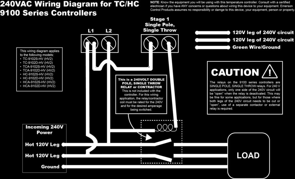
11 Wiring Diagrams 11
12 This page intentionally blank. 12


13 1724 Lake Drive West Chanhassen, MN USA MADE IN USA Printed in the USA DOCUMENT #: D 13
Installation, Testing, and Operating Procedures 30 AMP PORTABLE AND PERMANENT SERIES GFCI SINGLE and MULTIPHASE
 IMPORTANT! Please read all the information on this sheet. SAVE THESE INSTRUCTIONS! NOTICE BEFORE USING READ INSTRUCTIONS COMPLETELY. TO BE INSTALLED BY A QUALIFIED ELECTRICIAN IN ACCORDANCE WITH NATIONAL
SP6R Level Controller Operation Manual
 SP6R Level Controller Operation Manual www.sjerhombus.com SP6R LEVEL CONTROLLER INTRODUCTION SJE-Rhombus, an industry leader in water and wastewater pump controls, introduces the SP6R Level Controller.
USER'S MANUAL DCL-650
 USER'S MANUAL Clamp on Multimeter - Compact Design True RMS AC/DC DCL-650 CIRCUIT-TEST ELECTRONICS www.circuittest.com Safety International Safety Symbols This symbol, adjacent to another symbol or terminal,
Rack Mount Power Supplies
 Rack Mount Power Supplies Installation Guide Models Include: VertiLine33D - 12VDC @ 8A - Sixteen (16) PTC protected outputs VertiLine33TD - 12VDC @ 16A - Sixteen (16) PTC protected outputs VertiLine63D
LAUREL ELECTRONICS, INC.
 LAUREL ELECTRONICS, INC. Laureate RTD Temperature Panel Meter / Controller Features Factory calibrated for 100Ω platinum, 10Ω copper & 120Ω nickel RTDs 2, 3 or 4-wire connection with lead resistance compensation
Mini Digital Multimeter
 User's Guide Mini Digital Multimeter Model MN15 99 Washington Street Melrose, MA 02176 Phone 781-665-1400 Toll Free 1-800-517-8431 Visit us at www.testequipmentdepot.com Back to the Extech MN15/MN16 Series
CM-220 True RMS AC CLAMP METER INSTRUCTION MANUAL
 CM-220 True RMS AC CLAMP METER INSTRUCTION MANUAL Safety International Safety Symbols This symbol, adjacent to another symbol or terminal, indicates the user must refer to the manual for further information.
Autoranging True RMS Multimeter User Manual
 Autoranging True RMS Multimeter User Manual Please read this manual before switching the unit on. Important safety information inside. Contents Page 1. Safety Information... 4 2. Safety Symbols... 5 3.
Mini Digital Multimeter
 User's Guide Mini Digital Multimeter Model MN15 Introduction Congratulations on your purchase of the Extech MN15 MultiMeter. The MN15 offers AC/DC Voltage, AC/DC Current, Resistance, Diode, and Continuity
BA/BS4S Temperature Sensor Installation & Operating Instructions
 Product Overview and Identification The BAPI-Stat 4 room temperature sensor features a large format LCD and slider setpoint adjustment. Additional options include button override and communication jack.
S66 Series Electronic Fan Speed Control
 FANs 121, 125, 1628.3 Product/Technical Bulletin S66 Issue Date 0918 S66 Series Electronic Fan Speed Control The S66 Series Electronic Fan Speed Control is designed to modulate the speed of single-phase,
DM-918 OPERATIONS MANUAL AUTORANGING MULTIMETER
 DM-918 OPERATIONS MANUAL AUTORANGING MULTIMETER SAFETY INFORMATION The following safety information must be observed to ensure maximum personal safety during the operation of this meter: This meter is
HT Series Wall Mount with Relay Setpoints, LCD, and Humidistat and Thermostat Control
 Wall Mount with Relay Setpoints, LCD, and Humidistat and Thermostat Control NOTICE This product is not intended for life or safety applications. Do not install this product in hazardous or classified locations.
Tracer VM Bluetooth Interface
 Tracer Bluetooth Interface Model number BTI-102 Operating Instructions General The Bluetooth Interface collects, transmits and saves data from Base Flowmeters installed in injection mold cooling circuits.
Mini Digital Multimeter
 User Manual Mini Digital Multimeter Model MN15A Additional User Manual Translations available at www.extech.com Introduction Congratulations on your purchase of the Extech MN15A MultiMeter. The MN15A offers
MYRIAD QLC 4-CHANNEL MONITOR/CONTROLLER INSTRUCTION MANUAL
 MYRIAD QLC 4-CHANNEL MONITOR/CONTROLLER INSTRUCTION MANUAL VISIT OUR WEBSITE SIGMACONTROLS.COM MYR QLC MANUAL 013114 2 TABLE OF CONTENTS INTRODUCTION 3 Ordering Information Specifications Features WIRING
Progressive Industries, Inc. EMS Electrical Management System
 Progressive Industries, Inc. EMS Electrical Management System Complete Installation Guide and Operating Instructions for: Model EMS-LCHW50 Rated at 240V/50A Manufactured by: Progressive Industries, Inc.
CDD Carbon Dioxide Transmitter
 Introduction The OSA CO2 transmitter uses Infrared Technology to monitor CO2 levels within a range of 0 2000 ppm and outputs a linear 4-20 ma or 0-5/0-10 Vdc signal. The enclosure is designed to operate
LAUREL. Laureate RTD Temperature Panel Meter / Controller ELECTRONICS, INC. Features. Description. Specifications
 LAUREL ELECTRONICS, INC. Laureate RTD Temperature Panel Meter / Controller Features Factory calibrated for 100Ω platinum, 10Ω copper & 120Ω nickel RTDs 2, 3 or 4-wire connection with lead resistance compensation
OPR Power Series AC to DC POWER SUPPLY SERIES WITH REMOTE MANAGEMENT AND ALARM SYSTEMS. Model Nos. OPR065-48S / OPR065-48R. Manual
 OPR Power Series AC to DC POWER SUPPLY SERIES WITH REMOTE MANAGEMENT AND ALARM SYSTEMS Model Nos. OPR065-48S / OPR065-48R Manual Revision F July 2009 Optimal Power Supplies LLC www.optimal-power.com i
PV Rapid Shutdown device
 PV Rapid Shutdown device Installation and Operation Manual Solis-RSD-1G(1:1) Solis-RSD-1G(2:2) Manufacturer: Ginlong (Ningbo) Technologies Co.,Ltd., Ningbo, Zhejiang, P.R.China US Office: 565 Metro Pl.
Basic Temperature and Limit Controllers
 Basic Temperature and Limit Controllers Basic Temperature and Limit Controller Provide Economical Solution for a Wide Range of Applications The basic and limit microprocessor-based controllers from Watlow
Model R5010. TRMS Digital Multimeter. Instruction Manual
 INSTRUMENTS Model R5010 TRMS Digital Multimeter Instruction Manual Table of Contents Safety...3-4 IEC1010 Overvoltage Installation Category... 3 Warnings... 4 Features... 5 Specifications...5-8 Instrument
EMS. Electrical Management System. Progressive Industries Incorporated Morrisville, North Carolina
 Progressive Industries Warranty Progressive warrants its products are free from defects in materials and workmanship for a period of three years. This is in lieu of all other warranties, obligations, or
1 Description. 2 Specifications. Product Installation Document. Honeywell 12 Clintonville Road Northford, CT
 Honeywell 12 Clintonville Road Northford, CT 06472 http://www.honeywellpower.com HP600ULACM4CB HP600ULACM8CB Access Control Power Supply/Charger with Power Distribution Controller PN 52395:A 1/05/06 ECN
Tempco Instruction Manual
 Tempco Instruction Manual 1/16 DIN Solid State Temperature Controller Relay Output Solid State Output For Heating Model Numbers: TEC-901, TEC-902, TEC-905 Temperature controls in this series are designed
Electrical Management System (EMS) EMS-HW30C & EMS-HW50C
 EMS-HW30C & EMS-HW50C") Electrical Management System (EMS) EMS-HW30C & EMS-HW50C Installation & Operating Guide for: Model EMS-HW30C Rated at 120V/30A and Model EMS-HW50C Rated at 240V/50A Surgio Says Lifetime Warranty on all
Electrical Management System (EMS) EMS-HW30C & EMS-HW50C Installation & Operating Guide for: Model EMS-HW30C Rated at 120V/30A and Model EMS-HW50C Rated at 240V/50A Surgio Says Lifetime Warranty on all
S-14 S-14. Compact Digital Multimeter. Compact Digital Multimeter
 S-14 Compact Digital Multimeter S-14 Compact Digital Multimeter SAFETY INFORMATION The following safety information must be observed to insure maximum personal safety during the operation at this meter
Basic Temperature and Limit Controllers. Provide Economical Solution for a Wide Range of Applications SPECIFICATION SHEET
 SPECIFICATION SHEET Basic Temperature and Limit Controllers Basic Temperature and Limit Controllers Provide Economical Solution for a Wide Range of Applications The basic and limit microprocessor-based
Instruction Manual. Electrical Management System (EMS) EMS-HW30C & EMS-HW50C
 EMS-HW30C & EMS-HW50C") Instruction Manual Electrical Management System (EMS) EMS-HW30C & EMS-HW50C EMS-HW50C EMS-HW30C! CAUTION These instructions are intended to provide assistance with the installation of this product, and
Instruction Manual Electrical Management System (EMS) EMS-HW30C & EMS-HW50C EMS-HW50C EMS-HW30C! CAUTION These instructions are intended to provide assistance with the installation of this product, and
OPERATING INSTRUCTION
 OPERATING INSTRUCTION AUTORANGING MULTIMETER MAX Ω F C 10A MAX every 15 min. COM V SAFETY INFORMATION The following safety information must be observed to insure maximum personal safety during the operation
Owner's Manual. True RMS Multimeter. Model No Safety Operation Maintenance Español
 Owner's Manual True RMS Multimeter Model No. 82023 CAUTION: Read, understand and follow Safety Rules and Operating Instructions in this manual before using this product. Safety Operation Maintenance Español
D15CC55UNVD K/KS. UNV DALI Dimming LED Driver 1500mA Constant Current Output Class 2, 55W Output DALI Dimming to 1% Performance.
 UNV DALI Dimming LED Driver 1500mA Constant Current Output Class 2, 55W Output DALI Dimming to 1% Performance Input Voltage 120 ~ 277 Vac Input Current Max 0.56 /120V 0.24/277V Input Power Max 63W Input
User's Guide. MiniTec TM Series Model MN25 MultiMeter
 User's Guide MiniTec TM Series Model MN25 MultiMeter Warranty EXTECH INSTRUMENTS CORPORATION warrants this instrument to be free of defects in parts and workmanship for one year from date of shipment (a
RE-82 RACK MOUNT DIMMER OWNERS MANUAL. 8 X 2400Watts. Revision /29/2007
 RE-82 RACK MOUNT DIMMER 8 X 2400Watts OWNERS MANUAL Revision 2.4 11/29/2007 Page 2 of 8 RE-82 CONTROL PANEL DESCRIPTION The RE-82 is an 8 channel dimmer with a maximum capacity of 2,400 watts per channel
INSTRUCTION MANUAL. Instruction Manual. Analog Multi-Tube Vortexer Digital Multi-Tube Vortexer
 INSTRUCTION MANUAL Instruction Manual Analog Multi-Tube Vortexer Digital Multi-Tube Vortexer Table of Contents Package Contents............ 1 Warranty............ 1 Installation............ 2 Maintenance
RangerBOSS Network Ready Constant Monitor Model CM2800
 RangerBOSS Network Ready Constant Monitor Model CM2800 Instruction Manual Contents 1 Description CM2800 1 Features 1 2 Installation Installation Instructions 2 Installation Diagram 3 3 Operation Wrist
Instruction Manual Standard Multi-Position Stirrers Advanced Multi-Position Stirrers
 Instruction Manual Standard Multi-Position Stirrers Advanced Multi-Position Stirrers Table of Contents Package Contents.............. 1 Warranty.............. 1 Installation.............. 2 Maintenance
2200 Series. Quick Start Guide SAFETY CHECKLIST. Safety Made Simple
 Safety Made Simple SAFETY CHECKLIST KEEP unqualified/unauthorized personnel away from the test area ARRANGE test stations in a safe and orderly manner NEVER touch products or connections during a test
Pump-Down Controller MODEL mA Input Scalable 4-20mA Output Duplex Pump Alternation Hand-Off-Auto Controls Dual Run-time Meters
 DESCRIPTION Pump-Down Controller Input Scalable Output Duplex Pump Alternation Hand-Off-Auto Controls Dual Run-time Meters The Model 4052 Pump-Down Controller provides total control for duplex pumping
INSTALLATION INSTRUCTIONS
 LIGHTING CONTROL PANELS 16 AND 24 RELAYS INSTALLATION INSTRUCTIONS INSTALLATION OVERVIEW The installation instructions contained in this document are provided as a guide for proper and reliable installation.
INSTALLATION, OPERATION & MAINTENANCE CRFF Series Wall Control Console. ECM Motors. ACC1-25 (Part # ) Revision:
 Revision:") INSTALLATION, OPERATION & MAINTENANCE CRFF Series Wall Control Console ACC1-25 (Part # 63971-002) ECM Motors Revision: 10.01.13 Page: 2 of 11 Table of Contents Safety Precautions...3 Overview...3 Specifications...4
INSTALLATION, OPERATION & MAINTENANCE CRFF Series Wall Control Console ACC1-25 (Part # 63971-002) ECM Motors Revision: 10.01.13 Page: 2 of 11 Table of Contents Safety Precautions...3 Overview...3 Specifications...4
Secured Series: Hub Plus Kit Single Door Controller Package Installation Manual
 Secured Series: Hub Plus Kit Single Door Controller Package Installation Manual This package is designed to simplify the connections to our Secured Series Hub Plus Controller. This will translate into
Electrical Management System (EMS) EMS-HW30C & EMS-HW50C
 EMS-HW30C & EMS-HW50C") Electrical Management System (EMS) EMS-HW30C & EMS-HW50C Installation & Operating Guide for: Model EMS-HW30C Rated at 120V/30A and Model EMS-HW50C Rated at 240V/50A Surgio Says Lifetime Warranty on all
Electrical Management System (EMS) EMS-HW30C & EMS-HW50C Installation & Operating Guide for: Model EMS-HW30C Rated at 120V/30A and Model EMS-HW50C Rated at 240V/50A Surgio Says Lifetime Warranty on all
INTRODUCTION. FX-1 Operations Manual. Standard Features. Optional Features. Read This Manual Completely Before Proceeding!
 INTRODUCTION The FX-1 Control is designed for use with all direct expansion, reverse cycle air conditioning systems. FX-1 has a universal power supply that operates on 115, 230, 50 or 60 Hz AC power. FX-
Owner s Manual. Isolate. Restore. Inspire! Power Conditioners Audio / Video Power Isolation Units Rack Mount / Consumer Series
 Owner s Manual 19 Pro Series Rack Mount (RK) Faceplate Isolate. 17 Consumer Series (C) Faceplate Available in Black (B) and Silver (S) Colours Restore. Power Conditioners Audio / Video Power Isolation
HT Series Wall Mount with Analog Setpoints, LCD, and Humidistat and Thermostat Control
 Wall Mount with Analog Setpoints, LCD, and Humidistat and Thermostat Control NOTICE This product is not intended for life or safety applications. Do not install this product in hazardous or classified
CDD4 Series Room CO2 Transmitter Installation Instructions
 CDD4 Series Room CO2 Transmitter Installation Instructions Introduction The CO2 transmitter uses Infrared Technology to monitor CO2 levels and outputs a linear 4-20 ma or 0-5/0-10 Vdc signal. Options include
M A C 3 Wind Speed Alarm & Controller
 M A C 3 Wind Speed Alarm & Controller Installation Instructions Thank you for purchasing the MAC3 wind speed alarm and controller. This manual is designed to lead you through a step-by-step process to
CRAGG RAILCHARGER Instruction Manual for 10DTC-12V 20DTC-12V 30DTC-24V 40DTC-12V 60DTC-12V
 CRAGG RAILCHARGER for 10DTC-12V 20DTC-12V 30DTC-24V 40DTC-12V 60DTC-12V Contents 1 Warnings, Cautions, and Notes... 1 2 Description... 2 3 Features... 2 3.1 STANDARD FEATURES... 2 3.2 CHARGER REGULATION...
Passive UTP Transceiver Hub with Integral Isolated Camera Power Installation Guide
 Passive UTP Transceiver Hub with Integral Isolated Installation Guide Models Include: HubWay8Di HubWay16Di - UL Listed eight (8) Channel Passive UTP - UL Listed sixteen (16) Channel Passive UTP Transceiver
CDR-RH Room CO 2, Temperature and Humidity Sensors (Controllers)
") Product sheet SN1.401 Type CDR-RH CDR-RH Room CO 2, Temperature and Humidity Sensors (Controllers) CDR-RH sensors are designed to detect carbon dioxide concentration, relative humidity and temperature
Product sheet SN1.401 Type CDR-RH CDR-RH Room CO 2, Temperature and Humidity Sensors (Controllers) CDR-RH sensors are designed to detect carbon dioxide concentration, relative humidity and temperature
Active UTP Transceiver Hub with Integral Isolated Camera Power Installation Guide
 Active UTP Transceiver Hub with Integral Isolated Installation Guide Models Include: HubWayLD8Di HubWayLD16Di - UL Listed eight (8) Channel Active UTP - UL Listed sixteen (16) Channel Active UTP Transceiver
24/7 Sprinkler Monitor. The Ultimate Rain/Freeze Sensor
 24/7 Sprinkler Monitor The Ultimate Rain/Freeze Sensor User s Manual PIONEER SALES, LTD. 5529 Redfield St. Dallas, TX 75235 Phone: (214) 276-0306 Fax: (214) 631-4218 Toll Free: 1-(866) 501-7745 1 Table
Installation, Operation and Maintenance Manual
 Document 481200 VGD-100 Vari-Green Drive Installation, Operation and Maintenance Manual Please read and save these instructions for future reference. Read carefully before attempting to assemble, install,
Energy Management System. Operation and Installation Manual
 Energy Management System Operation and Installation Manual AA Portable Power Corp 825 S 19 TH Street, Richmond, CA 94804 www.batteryspace.com Table of Contents 1 Introduction 3 2. Packing List 5 3. Specifications
Installation Job Aid for VSP 4850GTS
 Installation Job Aid for VSP 4850GTS Notices Release 6.1.0.0 NN46251-308 Issue 02.01 November 2017 Notice paragraphs alert you about issues that require your attention. The following paragraphs describe
User Guide True RMS Multimeter Extech EX205T
 User Guide Extech EX205T True RMS Digital Multimeter Extech EX210T True RMS Digital Multimeter IR True RMS Multimeter Extech EX205T Introduction Thank you for selecting the Extech EX205T True RMS Auto-ranging
Contact form. Operating Force. Plunger SPDT 204g Dust- Proof (in closed position) Plunger SPST-NC 204g Dust- Proof (in closed position)
 Plunger SPST-NC 204g Dust- Proof (in closed position)") D3D Miniature Door Switch Appliance industry standard plunger and lever actuator styles High contact reliability ensured using gold alloy crossbar contacts Drip/spill sealing in free position (plunger
D3D Miniature Door Switch Appliance industry standard plunger and lever actuator styles High contact reliability ensured using gold alloy crossbar contacts Drip/spill sealing in free position (plunger
Instruction Manual HPH-8
 Specifications HPH-8 Trigger cable 120-volt, Nema 1-15 Main Power 50-amps @ 240-volt AC Power receptacles (4) Nema 5-15 or 6-15 Maximum HID wattage 8000 watts (on 240-volt) 4800 watts (on 120-volt) Maximum
AutoRanging Digital MultiMeter
 Owner's Manual AutoRanging Digital MultiMeter Model No. 82175 CAUTION: Read, understand and follow Safety Rules and Operating Instructions in this manual before using this product. Safety Operation Maintenance
MICRO GROW GREENHOUSE SYSTEMS, INC
 MICRO GROW GREENHOUSE SYSTEMS, INC 4065 ZEVO DR., UNIT B-, TEMECULA, CA 9590 PHONE (95) 96-3340 FAX (95) 96-3350 www.microgrow.com Revision., -09-0 Growstat Control Series INSTALLATION PROCEDURES SERIES
ETM-2050/ETM-2051 Service Manual
 Introduction Novar s Electronic Thermostat Modules (ETMs) are intelligent control modules that provide local, direct digital control of unitary, packaged, staged HVAC systems. This document: Describes
SAVE THESE INSTRUCTIONS
 OUTDOOR HARDWIRE INSTALLATION INSTRUCTIONS Please read and save these instructions. Read carefully before using product. Protect yourself and others by observing all safety information, warnings and cautions.
Transceiver Hub with Integral Camera Power
 Passive UTP Transceiver Hub with Integral Installation Guide Models Include: HubWay8CD HubWay16CD - UL Listed eight (8) Channel Passive UTP - UL Listed sixteen (16) Channel Passive UTP Transceiver Hub
NSI DIGITAL DIMMING SYSTEM DDS 5300 / 5600 DIMMER PACK
 INTRODUCTION NSI DIGITAL DIMMING SYSTEM INSTALLATION AND OPERATION GUIDE The NSI DDS 5300 and DDS 5600 dimmers represent a key part of a state of the art, integrated lighting control system. These dimmers
MTP INSTRUCTION MANUAL
 DT-118B MTP INSTRUCTION MANUAL Pocket Autoranging Digital Multimeter 3 in 1 Model MTP-1025 Auto Ran ging DMM Hz% A OFF V AU TO PO WER OFF MTP Instruments Table of Contents Introduction Page 1 Features
DEVAR Inc. Model d-rtti User Manual
 DEVAR Inc. Model d-rtti User Manual Introduction The Model d-rtti is a room temperature indicator/transmitter that provides an accurate indication of ambient temperature with a numeric readout and a 4
Installation Instructions for Eaton Surge Protective Device XXCFXXX10-DIN and XXCFXXX10-DIN2
 Supersedes 6/2015 Surge Protective Device XXCFXXX10-DIN and XXCFXXX10-DIN2 XXCFXXX10-DIN Contents Description Page 1.0 Setup...2 1.1 Before Installation...2 1.2 Installation...3 For AC Applications...3
2 Table of Contents 1. TABLE OF CONTENTS. 1. Table of Contents Introduction Wiring Diagram Terminals Review...
 TPR-6 Temperature Protection Relay Instruction Manual Ver. June 1 st 2010 2 Table of Contents 1. TABLE OF CONTENTS 1. Table of Contents... 2 2. Introduction... 3 3. Wiring Diagram... 5 4. Terminals Review...
Active UTP Transceiver Hub with Integral Isolated Camera Power
 Active UTP Transceiver Hub with Integral Isolated Installation Guide HubWayEX16SP - UL Listed sixteen (16) Channel Active UTP Transceiver Hub with Integral Isolated Rev. 011810 More than just power. TM
CO2 Controller Operating Instructions Models: RAD-0501, RAD-0501A, RAD-0501E 1. Product Description
 CO2 Controller Operating Instructions Models: RAD-0501, RAD-0501A, RAD-0501E 1. Product Description RAD-0501 Greenhouse Mode: Controls CO2 generator or regulator to increase CO2 levels during daylight
PLEASE READ INSTRUCTIONS CAREFULLY BEFORE INSTALLATION!
 TUC2 / TUCH2 Model Series Installation Instructions PLEASE READ INSTRUCTIONS CAREFULLY BEFORE INSTALLATION! APPLICATION The TUC2 provides temperature space monitoring with a backlit LCD. The TUCH2 provides
12-36 VDC/12-24 VAC Power Option 4-Digit Display, 0.56 (14.2 mm) or 1.20 (30.5 mm)
 or 1.20 (30.5 mm)") 4-20 ma & Relay Output Features 4-20 ma, ± 10 V, TC & RTD Inputs 12-36 VDC/12-24 VAC Power Option 4-Digit Display, 0.56 (14.2 mm) or 1.20 (30.5 mm) 24 VDC @ 200 ma Transmitter Power Supply Options Type
4-20 ma & Relay Output Features 4-20 ma, ± 10 V, TC & RTD Inputs 12-36 VDC/12-24 VAC Power Option 4-Digit Display, 0.56 (14.2 mm) or 1.20 (30.5 mm) 24 VDC @ 200 ma Transmitter Power Supply Options Type
VC3000 Series Line Voltage Switching Relay Pack Controllers Installation Guide
 Beyond Comfort VC3000 Series Line Voltage Switching Relay Pack Controllers Installation Guide August 10 th, 2010 (For Commercial and Lodging HVAC Fan Coil Applications) 028-0296-R1-LIT-VC3000-E01 Index
SERIES 59. Microprocessor Temperature Controller with Digital Display and RTD, Thermistor or Thermocouple Sensing
 SERIES 59 Microprocessor Temperature Controller with Digital Display and RTD, Thermistor or Thermocouple Sensing FEATURES Microprocessor-based no cumbersome menus Large 3-digit LED display permits easy
MAINTENANCE MANUAL. EDACS REDUNDANT POWER SUPPLY SYSTEM 350A1441P1 and P2 POWER MODULE CHASSIS 350A1441P3, P4, AND P5 POWER MODULES TABLE OF CONTENTS
 MAINTENANCE MANUAL EDACS REDUNDANT POWER SUPPLY SYSTEM 350A1441P1 and P2 POWER MODULE CHASSIS 350A1441P3, P4, AND P5 POWER MODULES TABLE OF CONTENTS SPECIFICATIONS*... 2 INTRODUCTION... 3 DESCRIPTION...
Autoranging Mini Multimeter
 User Manual Autoranging Mini Multimeter Model MN16A Additional User Manual Translations available at www.extech.com Introduction Congratulations on your purchase of the Extech MN16A Autoranging Multimeter.
NEUROLOGIC RESEARCH CORPORATION MODEL 2500
 NEUROLOGIC RESEARCH CORPORATION MODEL 2500 NETWORK HUMISTAT Compact, self-contained dehumidifier controller. 0.5 degrees C accuracy typical. RH sensor is digitally calibrated for 2% accuracy. Open communication
2.) Cabinet setup and preset data shall, as standard, be fully user programmable on a per cabinet or system wide basis.
 Cabinet setup and preset data shall, as standard, be fully user programmable on a per cabinet or system wide basis.") A21 DIMMER CABINET SPECIFICATION. GENERAL. A.) Overview. 1.) The dimmer cabinets shall be fully digital, designed specifically for architectural and entertainment lighting applications, and shall consist
A21 DIMMER CABINET SPECIFICATION. GENERAL. A.) Overview. 1.) The dimmer cabinets shall be fully digital, designed specifically for architectural and entertainment lighting applications, and shall consist
P216. Condenser fan speed controller. Product bulletin. Features
 P216 Condenser fan speed controller Product bulletin These controllers are designed for speed variation of single phase motors, especially for fan speed control on air cooled condensers. Head pressure
HCS-3600 / 3602 / 3604 Laboratory Grade & High RFI Immunity Switching Mode Power Supply with Rotary Encoder Control
 HCS-3600 / 3602 / 3604 Laboratory Grade & High RFI Immunity Switching Mode Power Supply with Rotary Encoder Control 1. INTRODUCTION User Manual This family of efficient, upgraded SMPS with small form factor,
User s Guide. 600A True RMS AC/DC Clamp Meter. Model 38389
 User s Guide 600A True RMS AC/DC Clamp Meter Model 38389 Safety International Safety Symbols This symbol, adjacent to another symbol or terminal, indicates the user must refer to the manual for further
Installation Instructions
 Please read all instructions before installing SPECIFICATIONS RT-100 Time Switch Programmable Countdown Voltage...120VAC, 60HZ Load (Single Pole Circuit) Incandescent or fluorescent lamp... 0 600 Watt
Models beginning with 2M, 2L or 2X. Product Description. Technical Specifications. Installation Instructions. Series 2000 Multiple Meter Units (MMUs)
") Models beginning with 2M, 2L or 2X Series 2000 Multiple Meter Units (MMUs) Product Description Technical Specifications Installation Instructions February 28 th, 2013 List of Figures...2 List of Tables...2
Models beginning with 2M, 2L or 2X Series 2000 Multiple Meter Units (MMUs) Product Description Technical Specifications Installation Instructions February 28 th, 2013 List of Figures...2 List of Tables...2
Active UTP Transceiver Hub with Integral Camera Power Installation Guide
 Active UTP Transceiver Hub with Integral Installation Guide Models Include: HubWayLD8CDS - UL Listed eight (8) Channel Active UTP Transceiver Hub with Integral HubWayLD82CDS - UL Listed eight (8) Channel
Instruction Manual. M Pump Motor Controller. For file reference, please record the following data:
 Instruction Manual M Pump Motor Controller For file reference, please record the following data: Model No: Serial No: Installation Date: Installation Location: When ordering replacement parts for your
Installation Instructions
 SPECIFICATIONS TS-400 InteliSwitch Digital Time Switch 20/277VAC Voltages... 20/277VAC, 50/60Hz Requirements @ 20VAC... 0-800W ballast @ 277VAC... 0-200W ballast @ 25VAC.../6 hp Time-Out Adjustment...
MAC3 Wind Speed Alarm & Controller. Installation Instructions
 MAC3 Wind Speed Alarm & Controller Installation Instructions Table of Contents Overview... 3 Installation... 3 Optional Equipment... 10 Dual Sensor Operation... 10 Other Optional Equipment... 10 Operation
RTT2 ROOM TEMPERATURE SWITCH. Mounting and operating instructions
 Mounting and operating instructions Table of contents SAFETY AND PRECAUTIONS PRODUCT DESCRIPTION ARTICLE CODES INTENDED AREA OF USE TECHNICAL DATA STANDARDS OPERATIONAL DIAGRAMS WIRING AND CONNECTIONS
User's Guide. Digital Multimeter. Model MN42
 User's Guide Digital Multimeter Model MN42 Introduction Congratulations on your purchase of the Extech MN42 MultiMeter. The MN42 offers AC/DC Voltage, DC Current, and Resistance testing. Proper use and
Indicators. Product Mounting Display Height Page
 Product Mounting Display Height Page EZ-ZONE PM 1 /32, 1 /16, 1 /8, 1 /4 DIN front panel Upper/Left: 0.30 to 0.80 in. (8 to 20 mm) Lower/Right: 0.22 to 0.50 in. (6 to 13 mm) 379 EZ-ZONE RUI and Gateway
MOBILE CONNECTOR - GEN 2 OWNER'S MANUAL
 MOBILE CONNECTOR - GEN 2 OWNER'S MANUAL UNITED STATES Contents Safety Information... 2 Save These Important Safety Instructions... 2 Warnings...2 Cautions...3 General Information... 4 Mobile Connector
CS XL XM. EcoSystem Bus Supply
 EcoSystem An EcoSystem lighting network containing more than one ballast, module, or driver requires an EcoSystem. This supply powers one or two independent EcoSystem buses with up to 64 ballasts or ballast
AirTest Model CN9000 Series Sensor Controller
 AirTest Model CN9000 Series Sensor Controller AirTest Model CN9000 Series Sensor Controller THEORY OF OPERATION A basic CN9000 configuration consists of Input/Process/Display combination modules, a 3 relay
U-150 Integrated Amplifier User s guide
 U-150 Integrated Amplifier User s guide U-150 Integrated Amplifier User s guide Specifications: Contents: Output: Phono: Line: Digital: Volume control: Dimensions: Weight: 2 300W/8 Ohm, 2 600W/4 Ohm Distortion:
IIM Warwick Court. Williamsburg VA REV 5
 1 1-757-258-3939 100 Warwick Court Williamsburg VA 23185 REV 5 2 Technical Specification >Accuracy Better than + 1% over a range of 1.5 to 200 amperes with power factor ranging from 1 to 0.5 Approved by
Mini Digital Multimeter Model MN15. User's Guide
 Mini Digital Multimeter Model MN15 User's Guide Introduction Congratulations on your purchase of the Extech MN15 MultiMeter. The MN15 offers AC/DC Voltage, AC/DC Current, Resistance, Diode, and Continuity
MICROFUSION FEATURES OPTIONS CERTIFICATIONS (PENDING) THREE PHASE SCR POWER CONTROLLERS
 THREE PHASE SCR POWER CONTROLLERS") MICROFUSION THREE PHASE SCR POWER CONTROLLERS FEATURES Auto-Ranging Input Voltage 24-600 VAC, 45-65 Hz AC Output 16, 32, 50, 80 Amps (@ 50 C 6000 ft) Control Features Microprocessor-based controller /
MICROFUSION THREE PHASE SCR POWER CONTROLLERS FEATURES Auto-Ranging Input Voltage 24-600 VAC, 45-65 Hz AC Output 16, 32, 50, 80 Amps (@ 50 C 6000 ft) Control Features Microprocessor-based controller /
Satellite INSTALLATION GUIDE
 N3 Satellite INSTALLATION GUIDE ! WARNING! Shock Hazard. May result in serious injury or death. Turn power OFF at circuit breaker or remove fuse. Damage to this product caused by wiring with power on voids