Humidity Temperature Transmitter User Guide
|
|
|
- Richard Foster
- 5 years ago
- Views:
Transcription


1 Page 1 of 29 XB Humidity Temperature Transmitter 2015; E-M-XB-V1_26
2 Page 2 of 29 Table of contents 1 Overview Dimensional drawings General description Power supply Measured parameters Calculated parameters Analog output signals Direct RTD option (XB2 and XB3) Service connector Sensor protection (dust filter)... 7 User configurable settings and functions Function overview Factory default settings Mechanical installation General guidelines Electrical installation General guidelines Wiring and terminal block diagrams Operation Minimum load requirements for the XB3 with voltage outputs XB2 and XB3 transmitters (analog outputs) Maintenance Service cable Location of the service connector (mini USB type) Periodic calibration check Cleaning or replacing the dust filter Validation of the output signals transmission Firmware updates Technical data Specifications Dew point accuracy Accessories Supporting documents Document releases ; E-M-XB-V1_26
3 Page 3 of 29 Applicability: This manual applies to all instruments of the XB transmitter series with firmware version 3.0 or higher. Changes to the last digit of the version number reflect minor firmware changes that do not affect the manner in which the instrument should be operated. 1 Overview The XB transmitter measures temperature, relative humidity and the dew or frost point and is designed for OEM applications. The XB transmitter consists of a probe that is hard wired to a small open board with a 2 m / 6.5 ft cable. Humidity is measured with the ROTRONIC HYGROMER IN-1 capacitive humidity sensor. This sensor offers fast response and exceptional stability, even in high humidity environments. Sensor durability has proven to be excellent in a wide range of applications. The XB transmitter is suitable for measuring humidity within the range of 0 to 100 %RH and temperature within the range of -100 to 200 C (-100 to 392 F) at the probe. At temperature values above 80 C, the maximum humidity to which the humidity sensor can be exposed is gradually limited. Both the probe and sensor survive exposure to temperature within the range of -100 to 200 C / -148 to 392 F. The probe of the XB transmitter is equipped with a Pt100 RTD temperature sensor. Data from this sensor is used to compensate the effect of temperature on the humidity sensor so as to maintain accurate humidity measurements over a wide range of temperature values. Depending on the model (see ordering codes), data from the RTD is also used to provide a linear temperature output signal As an option, the probe of the XB transmitter can be equipped with an additional Pt100 RTD temperature sensor. In that case, the XB transmitter is equipped with a 4-position terminal block for direct connection to the temperature sensor. Two basic types of electronic circuit are available: XB2: 2-wire, loop powered (4 20 ma current signal) and XB3: 3-wire (voltage or current signal). The analog output signal is linear and can be transmitted over a length of cable to a remote display, recorder, controller or data processing unit. Digital signal processing within the XB transmitter ensures consistent product performance and also facilitates the task of field maintenance: Based on the ROTRONIC AirChip 3000 digital technology, the XB transmitter series offers the following user functions which can only be accessed with the HW4 software: User configurable settings Calculation of the dew or frost point Humidity temperature calibration and adjustment Simulator mode Automatic humidity sensor test and drift compensation Sensor failure mode Data recording The ability for the user to easily update the AirChip 3000 firmware means that instruments of the XB series can be kept up-to-date regarding any future functionality improvement. 2015; E-M-XB-V1_26
4 Page 4 of 29 2 Dimensional drawings Dimensions in mm Board thickness: 1.7 mm / 0.07 Clearance bottom: 5 mm / 0.20 V+ V- Clearance top (component side): 15 mm / x mounting hole dia: 4.4 mm / Overall probe length: 116 / 266 mm (4.57 / ) Diameter: 15 mm (0.59 ) Cable length: 2 m (6.5 ft) 2015; E-M-XB-V1_26
5 Page 5 of 29 3 General description 3.1 Power supply Depending on the circuit type, the XB transmitter requires the following power supply: a) XB2 (2-wire, loop powered): VDC - depending on the load connected to the output(s). The minimum supply voltage can be determined as follows: V min = 10 V + (0.02 x Load*) *Load resistance in ohms. For the maximum load of 500 Ω, the minimum supply voltage is 10 + (0.02 x 500) = 20 VDC. With both output circuits closed, the maximum current consumption is 40 ma. b) XB3 (3-wire with analog outputs): 15 to 40 VDC (see note below) or 12 to 28 VAC. With both output circuits closed, the maximum current consumption is 50 ma. Note: depending on the type of output signal, the XB3 will operate with the following minimum voltage 0 1 V outputs: 6 VDC or 5 VAC 0 5 V outputs: 10 VDC or 8 VAC 0 10 V outputs: 18 VDC or 13 VAC 0 20 ma or 4 20 ma outputs: 6 VDC or 5 VAC with 0 Ω load 18 VDC or 13power with 500 Ω load 3.2 Measured parameters The XB transmitter measures relative humidity with a ROTRONIC Hygromer IN1 capacitive sensor and temperature with a Pt100 RTD. 3.3 Calculated parameters Using the ROTRONIC HW4 software, the XB transmitter can be configured by the user to calculate either the dew point or the frost point. 2015; E-M-XB-V1_26
6 Page 6 of Analog output signals XB2 and XB3 With the ROTRONIC HW4 software any of the two analog output signals can be made to correspond to one of the following: Relative humidity Temperature Dew or frost point Any output can also be disabled. The scale of each analog output can be set within the numerical limits of and The D/A converters used to generate the analog output signals feature a 16-bit resolution and exhibit a small positive offset at the bottom of the signal range as indicated below:. Signal type 0 1 V 10 mv 0 5 V 50 mv 0 10 V 100 mv 0 20 ma 0.2 ma 4 20 ma No offset XB3 Maximum offset at range bottom The ROTRONIC HW4 software allows changing the type of output signal to one of the following: 0 20 ma, 4 20 ma, 0 1V, 0 5V or 0 10V. Both output signals are automatically configured with the same signal type. No calibration or adjustment is required after changing the type of output signal. In the case of voltage output signals, load requirements apply to the external device or circuit connected to the XB3 transmitter. These requirements are defined in the Operation chapter 3.5 Direct RTD option (XB2 and XB3) The standard XB transmitter is equipped with one Pt100 RTD. When ordered with the direct RTD option, the XB transmitter is supplied with a second Pt100 RTD installed on the probe. This additional RTD is directly connected to a terminal block. (4-wire connection) 2015; E-M-XB-V1_26
7 Page 7 of Service connector The service connector is a UART digital interface (Universal Asynchronous Receiver Transmitter) with a mini- USB type connector. This allows connecting the XB transmitter either to a PC running the ROTRONIC HW4 software or to a probe input of another instrument that is compatible with the HygroClip 2 (HC2) probes. In both cases a service cable is required. See Maintenance for the location of the service connector and for the type of service cable to be used. Connecting the XB transmitter to a PC is used to configure the transmitter, gain access to the transmitter functions such as humidity and temperature adjustment, read data from the transmitter on the PC and update the AirChip 3000 firmware. Connecting the XB transmitter to the probe input of another instrument is useful only when the other instrument has its own display and keypad, and has an internal menu equivalent to the menu of the HP23 hand-held calibrator. The connection allows showing the data measured by the XB transmitter on the other instrument display and also allows using the other instrument internal menu to do for example a humidity and temperature adjustment of the XB transmitter. 3.7 Sensor protection (dust filter) A dust filter is required to protect the sensors against dust particles and high air velocity. The probe of the XB transmitter is equipped with a with a metal filter base mod. NSP-ME. The filter cartridge must be ordered separately (see Accessories 11.5). Filter cartridge mod. SP-M15 is suitable for most applications. 2015; E-M-XB-V1_26
8 Page 8 of 29 User configurable settings and functions The XB transmitter ships configured as specified on the customer order. The analog outputs can be used just as with any conventional humidity and temperature transmitter and most users will never need to use the XB transmitter configurable settings and functions. Making use of the XB transmitter configurable settings and functions is entirely up to the user and the appropriate settings depend on the user application. We have provided below a short description of the XB transmitter functions and also indicated the factory default settings. 3.8 Function overview MEASUREMENT ACCURACY AND RELIABILITY AirChip 3000 Functions Humidity / temperature adjustment Automatic humidity sensor test and optional drift compensation Data recording Description o 1-point or multi-point humidity calibration or adjustment o 1-point or 2-point temperature calibration or adjustment o Generate a time stamp for calibrations and adjustments o Retain and view last adjustment date and adjustment values o Generate calibration and adjustment protocols Tests the humidity sensor for drift caused by contaminants and can be used to automatically apply a correction. The test is automatically carried out at regular intervals of time. Can be configured, enabled, or disabled The humidity sensor status can be verified either with the HW4 software and is shown as Good, SQ-tuned (corrected for drift) or Bad (defective) The data recording function differs from a true data logging function in the sense that the AirChip 3000 does not time stamp the data. This data recording function can be used to investigate events such as a sensor malfunction as well as to retrieve data that would otherwise be lost o Start or stop data recording - up to 2000 value pairs (%RH and temperature). Starting a recording session erases all previously recorded data o The recording mode and log interval can be specified o When the device is powered off, the recording session is paused but not ended As long as the recording session has not been ended, the device automatically resumes recording data when powered up again o The recorded data can be downloaded to a PC with the HW4 software, time stamped and viewed MEASUREMENT LOOP VALIDATION AirChip 3000 Functions Simulator mode Description Used to make the XB transmitter generate fixed values for the humidity, temperature and calculated parameter. Can be configured, enabled or disabled 2015; E-M-XB-V1_26
9 Page 9 of 29 DEVICE SAFEGUARDS AirChip 3000 Functions Device write protection Description Used to protect the XB transmitter with a password to prevent unauthorized digital access by a digital user. Can be configured, enabled or disabled PROCESS PROTECTION / PROTECTION OF OTHER DEVICES AirChip 3000 Functions Limit humidity output to 100 %RH Out-of-limit value alarm Description Used to prevent the humidity signal from exceeding 100 %RH when condensation forms on the sensor. Can be enabled or disabled Used to specify the normal range for humidity, temperature and the calculated parameter depending on the user application. Can be configured, enabled or disabled Bad sensor alarm Fail safe mode Out-of-limit values trigger a digital alarm which can be also be seen on the optional display Built-in function. Cannot be disabled A bad humidity or temperature sensor triggers a digital alarm which can be also be seen on the optional display Used to specify a "safe" fixed value for humidity and for temperature in the event of a sensor failure. Can be configured, enabled or disabled 2015; E-M-XB-V1_26
10 Page 10 of Factory default settings Configuration of the XB transmitter by the user and access to its functions requires a PC with the ROTRONIC HW4 software (version or higher) installed. Service cable AC3006 or AC3009 is used to connect the XB service connector to a USB port of the PC (see Maintenance > Service Cable). Configurable Settings Applicability Factory default system (Metric or English) XB2, XB3 As per ordering code Analog signal type (4 20 ma or other) XB3 As per ordering code Psychrometric calculation XB2, XB3 As per ordering code Output 1 parameter, scale and unit XB2, XB3 As per ordering code (%RH or DP) Output 2 parameter, scale and unit XB2, XB3 Temperature, unit as per ordering code Functions Applicability Factory default Humidity / temperature adjustment XB2, XB3 Device write protection XB2, XB3 Disabled Limit humidity output to 100 %RH XB2, XB3 Enabled Out-of-limit value digital / display alarm XB2, XB3 Disabled Data recording XB2, XB3 Automatic humidity sensor test XB2, XB3 Disabled Humidity sensor drift compensation XB2, XB3 Disabled Fail safe mode XB2, XB3 Disabled Simulator mode XB2, XB3 Disabled Enabled (loop mode 10 min. interval) For a detailed description of all AirChip 3000 / XB transmitter main functions see document E-T-AC3000-DF-V1 Instructions regarding the configuration of the XB transmitter and access to its functions are provided in the following manuals: E-M-HW4v3-Main E-M-HW4v3-F2-009 E-M-HW4v3-DR-001 E-M-HW4v3-A2-001 The factory default setting for dew / frost point calculation is frost point below freezing 2015; E-M-XB-V1_26
11 Page 11 of 29 4 Mechanical installation 4.1 General guidelines Relative humidity is extremely dependent on temperature. Proper measurement of relative humidity requires that the probe and its sensors be at exactly the temperature of the environment to be measured. Because of this, the location where you choose to install the probe can have a significant effect on the performance of the instrument. The following guidelines should guarantee good instrument performance: a) Select a representative location: install the probe where humidity, temperature and pressure conditions are representative of the environment to be measured. b) Provide good air movement at the probe: air velocity of at least 200 ft/ minute (1 meter/second) facilitates adaptation of the probe to changing temperature. c) Avoid the following: (1) Close proximity of the probe to a heating element, a cooling coil, a cold or hot wall, direct exposure to sun rays, etc. (2) Close proximity of the probe to a steam injector, humidifier, direct exposure to precipitation, etc. (3) Unstable pressure conditions resulting from excessive air turbulence. d) Immerse as much of the probe as possible in the environment to be measured. e) Prevent the accumulation of condensation water at the level of the sensor leads. Install the probe so that the probe tip is looking downward. If this is not possible, install the probe horizontally. Insufficient probe immersion typically creates errors in the measurement of both humidity and temperature and may even cause a malfunction. Standard 100 mm (3.9 ) probe: this probe is generally not suitable for through wall installation and is designed for full immersion in the environment to be measured. At least 15 to 20 of the probe cable should be inserted together with the probe. Optional 250 mm (9.8 ) probe: this probe is designed for through wall installation. To facilitate probe installation and removal, we recommend using a probe holder mod. QMA-15. This holder is a mounting flange that is equipped with a compression fitting. 2015; E-M-XB-V1_26

12 Page 12 of 29 Installation of the 250 mm or longer probe Make sure that about 230 mm (9 ) of the probe are immersed in the environment to be measured. AC1306 and AC1304-M Wall Installation Note: You may want to provide an orifice at a distance of about 3 from the probe of the transmitter for future use by a reference probe and HygroPalm indicator. Mounting hardware: Part AC 1306 is a flange and part AC1304-M is a compression fitting designed to hold the probe of the XB transmitter when mounted through a wall (see Accessories). 2015; E-M-XB-V1_26
13 Page 13 of 29 5 Electrical installation 5.1 General guidelines Power supply wiring Heavy machinery and instrumentation should not share the same power supply wiring. If this cannot be avoided, noise filters and surge protectors should be used. Most UPS devices have those features already integrated. General guidelines for signal cables The following guidelines are derived from European Standard EN for the transmission of signals by copper wires. When planning an installation, the rules provided by EN should be followed under consideration of local circumstances to determine the position of machines and equipment. All ROTRONIC products are tested for Electromagnetic Compatibility according to EMC Directive 2004/106/EG and following European standards: - EN : 2001, EN : EN : 2005, EN : A11 Whenever the level of electromagnetic interference is expected to be high, both the instruments and signal cables should be placed as far away as possible from the source of interference. In general, signal cables should be installed in bundles or channels / conduits, separate from other cables as indicated in the table below: Bus signals such as RS485 Data signals for PCs, printers etc. shielded analog inputs unshielded direct current (<= 60V) shielded process signals (<= 25 V) unshielded alternate current (<= 25V) coaxial cables for CRT monitors direct current from 60 V to 400 V (unshielded) alternate current from 25V to 400 V (unshielded) direct and alternate current > 400 V (unshielded) Telephone lines lines leading into EX-rated areas in common bundles or channels / conduits in separated bundles or channels / conduits, without minimum distance in separated bundles or channels / conduits, without minimum distance Lightning protection Cabling in areas with a risk of lightning requires a lightning protection. For cabling underground in between buildings, we recommend the use of special fiber optic cables. If this is not possible, use copper cables that are suitable for underground installation. 2015; E-M-XB-V1_26
14 Page 14 of Wiring and terminal block diagrams XB2: 2-wire, loop powered transmitter Electrical diagram The maximum permissible cable length connecting the XB2 to other devices is determined by the total resistance resulting from the addition of the cable resistance and that of the devices connected in series with the unit. This resistance should not exceed 500 ohms. 2015; E-M-XB-V1_26
15 Page 15 of 29 Terminal block diagram Terminals Description K1-1: H+V Power supply: VDC (+) K1-2: H-OUT Relative humidity or dew point (+) OUT-1 K1-3: T+V Power supply: VDC (+) K1-4: T-OUT Temperature output (+) OUT-2 Note: Connect the + of the power supply to only one of the V+ terminals. The two terminals marked H+V and T+V are internally connected. Measuring humidity or temperature only Unless configured to measure either humidity only or temperature only, proper operation of the XB2 requires both current loops to be closed. The XB2 can be directly ordered from the factory to measure either humidity or temperature only. When necessary, any unused output of the XB2 can be disabled with the ROTRONIC HW4 software. When the XB2 is configured with one of the two outputs disabled, close only the loop that is being used. 2015; E-M-XB-V1_26

16 Page 16 of XB3: 3-wire transmitter Electrical diagram for voltage outputs The maximum permissible cable length can be determined under consideration of the voltage drop caused by the current flowing to the devices connected to the unit. The voltage drop in the cable depends both on cable resistance and on the equivalent resistance of the devices connected in parallel to the unit. The total resistance connected to each unit output should be at least 1000 ohms. Cable resistance should not be more than 1/1000 of the load resistance. Minimum load requirements apply to the external device or circuit connected to the XB3 transmitter. These requirements are defined in the Operation chapter Electrical diagram for current outputs The maximum permissible cable length, connecting the unit to other devices, is determined by the total resistance resulting from the addition of the cable resistance and that of the devices connected in series with the unit. This resistance should not exceed 500 ohms. 2015; E-M-XB-V1_26
17 Page 17 of 29 Terminal block diagram Terminals Description K1-1: OUT1 Relative humidity or dew point (+) K1-2: OUT2 Temperature output (+) V+ V- K1-3: GND K1-4: GND K2-1: V+ K2-2: V- Ground (tied with other GND) Ground (tied with other GND) Power supply: VDC (+) or VAC (Phase) Power supply (-) or neutral (tied with other GND) Measuring humidity or temperature only Operation of the XB3 does not require both current loops to be closed. When using the XB3 to measure either humidity only or temperature only, close only the loop that is being used. Using the ROTRONIC HW4 software, any unused output of the XB3 can be disabled. 2015; E-M-XB-V1_26
18 Page 18 of Optional terminal block - Pt100 direct (XB2 and XB3) Terminal block K3 is present only when the XB transmitter is equipped with an additional Pt100 RTD installed on the probe Terminals Description K3-1 Pt100 direct - R K3-2 Pt100 direct - AR K3-3 Pt100 direct AS PT_S_DIREKT PT_AS_DIREKT PT_AR_DIREKT PT_R_DIREKT K3-4 Pt100 direct S Grounding We generally recommend grounding the (-) side of the power supply, especially if the electronics will be subjected to a low humidity environment (35 %RH or less). 2015; E-M-XB-V1_26
19 Page 19 of 29 6 Operation 6.1 Minimum load requirements for the XB3 with voltage outputs The following requirements apply to any external device or circuit connected to the XB3 transmitter with voltage outputs: XB3 Voltage Output RL XB3 output signal 0 1V Input resistance RL >=1kOhm 0 5V >=5kOhm 0 10V >=10kOhm GND In the situation where the external device uses an internal pull-up resistor the value of this resistor should meet the requirements shown below. It is also necessary to add a pull-down resistor RL connected to ground in order to be able to read 100% of the range of the XB3 voltage output. XB3 Voltage Output VCC R Pull-up RL GND XB3 signal VCC R pull-up RL 0 1V 3.3V 250 kohm 1 kohm XB3 signal VCC R pull-up RL 0 1V 5.0V 400 kohm 1 kohm 0 5V 5.0V 400 kohm 5 kohm XB3 signal VCC R pull-up RL 0 1V 10.0V 1 MOhm 1 kohm 0 5V 10.0V 1 MOhm 5 kohm 0 10V 10.0V 1 MOhm 10 kohm 6.2 XB2 and XB3 transmitters (analog outputs) If so desired, use the HW4 software to configure the XB transmitter. Complete the mechanical and electrical installation and simply power up the transmitter. 2015; E-M-XB-V1_26
20 Page 20 of 29 7 Maintenance 7.1 Service cable IMPORTANT: Use service cable AC3009 with the 2-wire, loop powered XB transmitter. This cable powers up the transmitter via the service connector. Do not use any other method for powering the transmitter when using this cable AC3009 as this will create a ground loop and damage the transmitter. For the same reasons do not use cable AC3006 with a 2-wire, loop powered transmitter. Use service cable AC3006 with the 3-wire XB transmitter. This cable does not provide power to the transmitter and the transmitter should powered separately when using this cable Both cables AC3006 and AC3009 convert UART (service connector) to USB and are used to connect the transmitter to a USB port of a PC running the ROTRONIC HW4 software. Prior to using any of these cables, the ROTRONIC USB driver must be installed on the PC. Both the driver and the installation instructions (document E-M-HW4v3-Main) are located on the HW4 CD. As an alternative, cable AC2001 is used to connect the XB transmitter to a probe input of the HP23 hand-held calibrator. For service purposes, the HP23 offers essentially the same functionality as the HW4 software. 2015; E-M-XB-V1_26
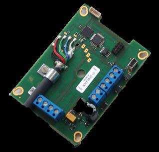
21 Page 21 of Location of the service connector (mini USB type) WARNING: the service connector is a UART interface with a mini-usb connector type. Do not connect the service connector directly to the USB port of a PC or hub. The service connector is located on the XB printed circuit board. Service Connector (Mini USB) V+ V- 2015; E-M-XB-V1_26
22 Page 22 of Periodic calibration check Both the Pt 100 RTD temperature sensor and associated electronics are very stable and should not require any calibration after the initial factory adjustment. Long term stability of the ROTRONIC Hygromer humidity sensor is typically better than 1 %RH per year. For maximum accuracy, calibration of the XB transmitter should be verified every 6 to 12 months. Applications where the XB transmitter is exposed to significant pollution may require more frequent verifications. Procedure for adjusting the XB transmitter with the ROTRONIC HW4 software: Use the appropriate model of service cable (see Maintenance > Service Cable) to connect the service connector of the XB transmitter to a USB port of a PC with the HW4 software installed. Note that the ROTRONIC USB driver must be installed on the PC as explained in the HW4 manual E-M-HW4v3- Main. Start HW4 on the PC and search for the XB transmitter (HW4 Main Menu Bar > Devices and Groups > Search for USB Masters). After finding the XB transmitter with HW4, expand the device tree to see the XB transmitter functions. Select Probe Adjustment. Instructions for using the ROTRONIC calibration devices and humidity standards are provided in document E-M-CalBasics For further instructions see HW4 manual E-M-HW4v3-A Cleaning or replacing the dust filter Depending on the conditions of measurement, the filter should be checked from time to time. Corroded, discolored or clogged filters should be replaced. The probe of the XB transmitter has a removable filter cartridge. Simply replace the cartridge (leave the metal base on the probe). 7.5 Validation of the output signals transmission If so desired, transmission of the XB transmitter output signals can be validated by using the simulator function. The HW4 software is required to enable and configure this function. When this function is enabled the XB transmitter generates fixed digital and analog signals as specified by the user. For instructions see document E-M-HW4v3-F ; E-M-XB-V1_26
23 Page 23 of 29 8 Firmware updates Firmware updates will be available on the ROTRONIC website for downloading. Firmware files are given a name that shows both to which device the file applies and the version number of the firmware. All firmware files have the extension HEX. Procedure for updating the firmware: Use the appropriate model of service cable (see Maintenance > Service Cable) to connect the service connector of the XB transmitter to a USB port of a PC with the ROTRONIC HW4 software installed. Note that the ROTRONIC USB driver must be installed on the PC as explained in the HW4 manual E- M-HW4v3-Main. Copy the firmware update file from the ROTRONIC website to the PC. Start HW4 software on the PC and search for the XB transmitter (HW4 Main Menu Bar > Devices and Groups > Search for USB Masters). After finding the XB transmitter, expand the device tree to see the XB transmitter functions. Select Device Manager. In the Device Manager menu bar select Tools > Firmware Update. For instructions see document E-M-HW4v3-F ; E-M-XB-V1_26
24 Page 24 of 29 9 Technical data 9.1 Specifications General XB2 XB3 Device type Humidity temperature transmitter Circuit type 2-wire, loop powered 3-wire Power supply and connections XB2 XB3 Supply voltage (VDD) VDC V min = 10 V + (0.02 x Load*) resistance in ohms. *Load VDC or VAC Nominal current consumption 2 x 20 ma <50 ma Electrical connections Terminal block Polarity protection Protective diode on V+ Humidity measurement XB2 XB3 Sensor Measuring range Measurement accuracy at 23 C Repeatability Long term stability Sensor time constant ROTRONIC Hygromer IN %RH ±1.0 %RH 0.3 %RH <1 %RH / year Typical 10 sec, 63% of a 35 to 80 %RH step change (1m/sec air flow at sensor) Temperature measurement XB2 XB3 Sensor Measuring range Measurement accuracy at 23 C ±0.2 C Repeatability 0.05 C Long term stability Sensor time constant Pt100 RTD, IEC 751 1/3 class B C (see also environmental limits) <0.1 C / year Typical 4 sec, 63% of a step change (1m/sec air flow at sensor) Calculated parameters XB2 XB3 Psychrometric calculations Dew or frost point (user configurable option) Start-up time and data refresh rate XB2 XB3 Start-up time 3.4 s (typical) 1.9 s (typical) Data refresh rate 3.4 s (typical) 1.7 s (typical) 2015; E-M-XB-V1_26
25 Page 25 of 29 Configurable analog outputs XB2 XB3 Output 1 Output 2 Factory default parameter Factory default scale Factory default parameter Factory default scale Output 1 and Output 2 Signal type Can be made to correspond to any parameter Relative humidity or dew / frost point As per ordering code Can be made to correspond to any parameter Temperature As per ordering code 4 20 ma Accuracy of analog output ±30 µa User configurable scaling limits Maximum offset at bottom of signal range Short circuit tolerant engineering units no offset Yes 0 20 ma 4 20 ma 0 1 V 0 5 V 0 10 V (user configurable) ±20 µa ±2 mv (0-1V) ±5 mv (0-10V) 0 1V signal range : 10 mv 0 5 V signal range : 50 mv 0 10 V signal range : 100 mv 0 20 ma signal range : 0.2 ma 4 20 ma signal range : no offset Maximum external load 500 Ω 500 Ω (current output) Minimum external load 0 Ω 1 kω (0 1 V output) 5 kω (0 5 V output) 10 kω (0 10 V output) 0 Ω (current output) Digital interface (service connector) XB2 XB3 Interface type UART (Universal Asynchronous Receiver Transmitter) Maximum service cable length 5 m (16.4 ft) General specifications XB2 XB3 Probe material Polycarbonate Probe dust filter material Depends on filter type Physical dimensions See Models Weight 225 g (8.0 oz) Conformity with standards XB2 XB3 CE / EMC immunity Solder type FDA / GAMP directives EMC Directive 2004/108/EG: EN : 2001, EN : 2005 EN : 2005, EN : A11 Lead free (RoHS directive) compatible 2015; E-M-XB-V1_26
26 Page 26 of 29 Environmental limits XB2 XB3 Storage and transit Operating limits at electronics Temperature limits at probe C Maximum humidity at sensor Maximum air velocity at probe Critical environments C %RH, non condensing C, %RH, non condensing 100 %RH up to 80 C (176 F) 70 %RH at 100 C (212 F) 30 %RH at 125 C (260 F) 15 %RH at 150 C (302 F) 8 %RH at 175 C (347 F) 4 %RH at 200 C (392 F) For more information s see humidity/temperature window of sensor. 40 m/s (7,870 ft /min) depends on dust filter type Humidity sensor: as per DV Critical chemicals 2015; E-M-XB-V1_26

27 Page 27 of Dew point accuracy The XB transmitter can be configured to calculate either the dew point or frost point based on the measurement of relative humidity and temperature. The accuracy of this conversion varies, depending on the humidity and temperature conditions as shown in the graph below: Example: At a temperature of 20 C, a dew point value of -37 C is measured with an accuracy of ±1.0 C or better. 2015; E-M-XB-V1_26
28 Page 28 of Accessories For accessories and parts such as the HW4 configuration software, service cables, calibration accessories and spare dust filters, please see document E-M-HC2-accessories 11 Supporting documents Document File Name E-M-HC2-accessories Contents Accessories and parts for probes, indicators and transmitters E-T-AC3000-DF-V1 AirChip 3000 Description and Main Functions E-M-HW4v3-DIR E-M-HW4v3-Main E-M-HW4v3-F2-009 E-M-HW4v3-A2-001 E-M-HW4v3-DR-001 E-M-AC3000-CP E-M-CalBasics E-T-HumiDefs List of the HW4 manuals HW4 software version 3: General instructions and functions common to all devices HW4 software version 3: Device Manager - XB transmitter HW4 software version 3: Probe Adjustment function AirChip 3000 devices HW4 software version 3: Data Recording Function AirChip 3000 Devices AirChip 3000 Communication Protocol Temperature and humidity adjustment basics Instructions for using the ROTRONIC humidity standards Humidity Definitions Note: All document file names have an extension corresponding to the document release number. This extension is not shown in the above table. 2015; E-M-XB-V1_26
29 Page 29 of Document releases Doc. Release Date Notes _20 Apr. 11, 2009 Original release _21 Jun. 20, 2010 Updated document to HW4 software v.3 _22 Oct. 28, 2011 _23 March 26, 2015 _24 April 01, 2015 Updated this document regarding the model of service cable to be used with 2-wire and 3-wire models. Changes for XB with firmware v3.0 Accuracy of analog outputs added Power supply specifications updated Offset specifications updated Picture on front side adapted for devices with firmware v3.x Drawing on page 4 adapted for devices with firmware v3.x _25 April 07, 2015 All descriptions of terminals adapted _26 October Maximum Humidity Sensor adaptation 2015; E-M-XB-V1_26
HygroFlex HF7 Humidity Temperature Transmitters. User Guide
 Page 1 of 22 HygroFlex HF7 Humidity Temperature Transmitters User Guide Page 2 of 22 Table of contents 1 Overview... 3 2 Mechanical configurations and dimensions... 4 3 General description... 5 3.1 Power
HygroFlex HF7 Humidity Temperature Transmitters. User Guide
 Page 1 of 27 HygroFlex HF7 Humidity Temperature Transmitters User Guide Page 2 of 27 Table of contents 1 Overview... 3 2 Mechanical configurations and dimensions... 4 3 General description... 5 3.1 Power
HygroFlex HF3 Transmitters. User Guide
 Page 1 of 27 HygroFlex HF3 Transmitters User Guide Page 2 of 27 Table of contents 1 Overview... 3 2 Mechanical configurations and dimensions... 4 2.1 Display option... 5 3 General description... 6 3.1
HygroFlex HF3 Transmitters and Thermohygrostats: User Guide
 Page 1 of 26 HygroFlex HF3 Transmitters and thermo-hygrostats Page 2 of 26 Table of contents 1 Overview... 3 2 Mechanical configurations and dimensions... 4 2.1 Display option... 5 3 General description...
HygroFlex TF5 Temperature Transmitter. User Guide
 Page 1 of 23 HygroFlex TF5 Temperature Transmitter Page 2 of 23 Table of contents 1 Overview... 3 2 Dimensional drawings... 4 2.1 Display and keypad option... 4 3 General description... 5 3.1 Power supply...
HygroLog HL20 and HL21 Data Logger. User Guide
 Page 1 of 17 HygroLog HL20 and HL21 Data Logger Page 2 of 17 Table of contents: 1. Overview... 3 1.1 General... 3 2. General description... 4 2.1 Models... 4 2.2 Required accessories... 4 2.3 Batteries...
HygroLog HL20 and HL21 Data Logger. User Guide
 Page 1 of 23 HygroLog HL20 and HL21 Data Logger Page 2 of 23 Table of contents: 1. Overview... 4 1.1 General... 4 2. General description... 5 2.1 Models... 5 2.2 Required accessories... 5 2.3 Batteries...
HygroClip2 ADVANCED Humidity Temperature Probes
 Humidity Temperature Probes 2016 ROTRONIC AG Bassersdorf Switzerland Table of contents 1 Overview... 3 1.1 Hardware and software compatibility... 3 2 Models... 4 3 General description... 18 3.1 Power supply...
HygroClip 2 (HC2) Humidity Temperature Probes User Guide
 Humidity Temperature Probes User Guide") Page 1 of 50 Probes User Guide Page 2 of 50 Table of contents 1 Overview... 3 1.1 Hardware and software compatibility... 3 2 Models... 4 3 General description... 25 3.1 Power supply... 25 3.2 Measured
Page 1 of 50 Probes User Guide Page 2 of 50 Table of contents 1 Overview... 3 1.1 Hardware and software compatibility... 3 2 Models... 4 3 General description... 25 3.1 Power supply... 25 3.2 Measured
HygroFlex5-EX Humidity & Temperature Transmitter Instruction Manual
 Page 1 of 24 HygroFlex5-EX Humidity & Temperature Page 2 of 24 Table of contents 1 General information... 3 1.1 About this manual... 3 1.2 Document versions... 3 1.3 Supporting documents... 3 2 Overview...
HM4. Humidity and Temperature Probe with Heated Sensor. Instruction Manual E-M-HM4-V1_12. HM4 Humidity and Temperature Probe with Heated Sensor
 Page 1 of 41 HM4 Humidity and Temperature Probe with Page 2 of 41 Table of Contents 1 Overview... 4 1.1 Scope... 5 1.2 Background Information on the Principle of Measurement... 5 2 Mechanical Variants
HygroClip DI Digital Interface for HygroClip Probes v 1.0 Instruction Manual
 HygroClip DI Digital Interface for HygroClip Probes v 1.0 Instruction Manual page 2 of 15 Contents: Overview... 2 Models... 3 Power... 4 Probes... 4 Connector identification... 5 Pin-out diagrams... 6
HygroClip M22 Series. 2-wire loop powered humidity temperature transmitters INSTRUCTION MANUAL
 HygroClip M22 Series 2-wire loop powered humidity temperature transmitters INSTRUCTION MANUAL 20060329 CONTENTS Overview... 3 Operation... 5 Power supply... 5 HygroClip S digital probe... 5 Temperature
HygroClip DIGITAL Humidity and temperature probe
 HygroClip DIGITAL Humidity and temperature probe 2016 ROTRONIC AG Bassersdorf Switzerland Contents 1 Overview... 3 1.1 Hardware and software compatibility... 3 2 Variants... 4 3 General information...
H290 HUMIDITY TRANSMITTER INSTRUCTION MANUAL
 H290 HUMIDITY TRANSMITTER INSTRUCTION MANUAL DESCRIPTION 4 OPERATION 4 Power Supply 4 Output Signal 4 Temperature Operating Range and Limits 4 Humidity Limits 5 Temperature Compensation 5 Sensor Protection
Table of contents: 1. HygroClip 2 in general. 2. The different probes. 3. Features in details. 4. Customer benefits. 5. Replacement overview
 HygroClip 2 Table of contents: 1. HygroClip 2 in general 2. The different probes 3. Features in details 4. Customer benefits 5. Replacement overview 1. HygroClip 2 in general The HC2-series are digital
HW4 Software version 3. HP23 Humidity Temperature Indicator
 Page 1 of 27 HW4 Software version 3 2010-2011; E-M-HW4v3-F2-012_11 Page 2 of 27 Table of contents 1 ORGANIZATION OF THE HW4 MANUALS... 3 2 OVERVIEW... 4 2.1 Functions and settings overview... 4 2.2 Detecting
HygroFlex. Humidity Temperature Transmitter. Instruction Manual
 HygroFlex Humidity Temperature Transmitter Instruction Manual v3 - 2 - Contents Overview...3 General Description...4 Power Requirements...4 Probes and Probe Inputs...5 Analog Outputs (HygroFlex 1 and HygroFlex
Humidity goes Digital
 Humidity goes Digital Networkable Industrial Transmitter Humidity, Temperature and Dew Point or other Computed Parameter Optional metal enclosure Unique HygroClip technology for superior performance Durable,
HC322 HUMIDITY / DEW POINT AND TEMPERATURE TRANSMITTER INSTRUCTION MANUAL
 HC322 HUMIDITY / DEW POINT AND TEMPERATURE TRANSMITTER INSTRUCTION MANUAL -2- INTRODUCTION...4 Temperature Limits at the Electronics...5 Operating Limits at the Sensors...5 Sensor Protection...6 INSTALLATION...6
HW4 Software version 3. Device Manager TF5 Temperature Transmitter
 Page 1 of 15 HW4 Software version 3 Device Manager 2010; E-M-HW4v3-F2-017_10 Table of contents Page 2 of 15 1 ORGANIZATION OF THE HW4 MANUALS... 3 2 OVERVIEW... 4 3 DEVICE MANAGER... 4 3.1 Device Manager
PCD DIGITAL Differential pressure probe
 Differential pressure probe 2016 ROTRONIC AG Bassersdorf Switzerland Contents 1 Overview... 3 1.1 Hardware and software compatibility... 3 2 Variants... 4 3 General information... 6 3.1 Power supply...
CLEAN ROOM PANEL - CRP5
 RELIABLE MEASUREMENTS IN CLEAN ROOMS Measures differential pressure, humidity and temperature Designed specifically for clean rooms Removable humidity and temperature probes for simpler adjustment and
HW4 Software version 2. Probe Adjustment function Legacy devices
 Page 1 of 12 HW4 Software version 2 Probe Adjustment function Page 2 of 12 Table of contents 1 ORGANIZATION OF THE HW4 MANUALS... 3 2 OVERVIEW... 4 3 PROBE ADJUSTMENT... 4 3.1 Overview... 5 3.2 Menu Bar...
Humidity goes Digital
 Industrial Humidity Temperature Transmitter Dew-point and other calculated values Wide range of digital interchangeable probes No need for field calibration PC compatible and RS485 networkable SWISS MADE
A1H Portable Humidity Temperature Indicator Instruction Manual
 A1H Portable Humidity Temperature Indicator Instruction Manual -2- CONTENTS Description...3 Operation...3 Measurement...4 Maintenance...4 Probe Installation and Removal...5 Output Connector...6 Accessories
DMT345 and DMT346 Dewpoint Transmitters
 DMT345 and DMT346 Dewpoint Transmitters for High Temperature Applications Features DMT345 measures humidity at temperatures up to 180 C (356 F) DMT346 measures humidity at temperatures up to 350 C (+662
TRANSMITTERS. HygroFlex & HygroClip-EX. Applications. Highlights
 HygroFlex & HygroClip-EX HygroFlex series may be used together with the intrinsically safe HygroClip-EX probes. The relative humidity and temperature can be displayed and output as analog signals. Calculated
HygroPalm 0. Portable Humidity Temperature Indicator. Instruction Manual
 HygroPalm 0 Portable Humidity Temperature Indicator Instruction Manual v 3 20040211 - 2 Contents Overview... 3 General Description... 3 Power Source... 3 Optional Docking Station (PD1-ACA)... 3 Unit System...
DWYER INSTRUMENTS, INC. Series AVUL Air Velocity Transmitter. Specifications - Installation and Operating Instructions.
 Series AVUL Air Velocity Transmitter Specifications - Installation and Operating Instructions Bulletin P-AVUL 3-49/64 [95.71] 2-43/64 [67.92] 1/2 NPS 3-3/16 [80.81] 1-19/32 [40.59] 31/32 24.58 3-33/64
RHT-WM-485-LCD Transmitter and RHT-DM-485-LCD Transmitter
 RHT-WM-485-LCD Transmitter and RHT-DM-485-LCD Transmitter TEMPERATURE AND HUMIDITY TRANSMITTER INSTRUCTIONS MANUAL V1.0x A 1 INTRODUCTION The RHT-WM-485-LCD and RHT-DM-485-LCD transmitters include high
CRP5 Clean Room Panel. Instruction Manual
 Page 1 of 36 CRP5 Clean Room Panel Page 2 of 36 Contents 1 Short Description of the Product... 3 1.1 Delivery Package... 4 1.2 Main Features of the CRP5... 5 1.3 Technical Drawings... 6 2 General Description...
Intelligence. humidity and temperature probes. Introducing AirChip Digital Technology.
 humidity and temperature probes Unique Sensing Intelligence. Introducing AirChip Digital Technology. Innovation in Humidity and Temperature Measurement Relative humidity, temperature measurement and dew
CRP5 Clean Room Panel. Instruction Manual
 Page 1 of 39 CRP5 Clean Room Panel 2018; Page 2 of 39 Contents 1 Short Description of the Product... 3 Delivery Package... 4 Main Features of the CRP5... 5 Technical Drawings... 6 2 General Description...
HW4 Software version 3. Device Manager HygroClip DI
 Page 1 of 10 HW4 Software version 3 2010 E-M-HW4v3-F1-003_10 Table of contents Page 2 of 10 1 ORGANIZATION OF THE HW4 MANUALS... 3 2 OVERVIEW... 4 3 DEVICE MANAGER... 4 3.1 Device Manager Menu Bar... 5
Transmitters RHT-WM-485-LCD, RHT-DM-485-LCD and RHT-P LCD
 Transmitters RHT-WM-485-LCD, RHT-DM-485-LCD and RHT-P10-485-LCD TEMPERATURE AND HUMIDITY TRANSMITTER INSTRUCTIONS MANUAL V1.0x D 1 INTRODUCTION The RHT-WM-485-LCD, RHT-DM-485-LCD and RHT-P10-485-LCD transmitters
MP 101A HUMIDITY TEMPERATURE PROBE INSTRUCTION MANUAL
 MP 101A HUMIDITY TEMPERATURE PROBE INSTRUCTION MANUAL -2- CONTENTS DESCRIPTION...3 OPERATION...3 INSTALLATION...4 MAINTENANCE...7 CALIBRATION BASICS...7 CALIBRATION PROCEDURE...8 SPECIFICATIONS...11 PLEASE,
DMT340 Series Dewpoint and Temperature Transmitters for Very Dry Conditions
 www.vaisala.com DMT340 Series Dewpoint and Temperature Transmitters for Very Dry Conditions The display shows measurement trends, real-time data, and measurement history. Features/Benefits Measures dew
HygroLog NT Humidity Temperature Data Logger. Instruction Manual
 HygroLog NT Humidity Temperature Data Logger Instruction Manual in-lognt-r11 02/15/2005 - 2 - Contents: DESCRIPTION... 3 Overview... 3 HygroLog NT - hardware description... 4 Models... 4 Memory... 4 Probes...
HygroLog NT Humidity Temperature Data Logger Instruction Manual
 HygroLog NT Humidity Temperature Data Logger Instruction Manual page 2 of 41 Contents: OVERVIEW... 4 HygroLog NT DATALOGGER... 5 Models... 5 Power... 5 Battery lifetime... 6 Battery replacement... 6 Probes...
MODEL: M5DY SEN TRONIC AG CURRENT LOOP SUPPLY. [2] POWER INPUT AC Power M: V AC (Operational voltage range V, Hz)
![MODEL: M5DY SEN TRONIC AG CURRENT LOOP SUPPLY. [2] POWER INPUT AC Power M: V AC (Operational voltage range V, Hz)](/thumbs/90/103899684.jpg "MODEL: M5DY SEN TRONIC AG CURRENT LOOP SUPPLY. [2] POWER INPUT AC Power M: V AC (Operational voltage range V, Hz)") Super-mini Terminal Block Signal Conditioners M5-UNIT CURRENT LOOP SUPPLY Functions & Features Powering a 0 ma DC current loop Applicable to smart transmitters Isolation between the input and output Fast
Super-mini Terminal Block Signal Conditioners M5-UNIT CURRENT LOOP SUPPLY Functions & Features Powering a 0 ma DC current loop Applicable to smart transmitters Isolation between the input and output Fast
1/32-DIN TEMPERATURE CONTROLLER INSTALLATION, WIRING AND OPERATION MANUAL FORM 3882
 1/32-DIN TEMPERATURE CONTROLLER INSTALLATION, WIRING AND OPERATION MANUAL FORM 3882 This manual is intended for use in support of installation, commissioning and configuration of the 1/32-DIN Temperature
USER MANUAL MULTI COLOR TOUCH SCREEN PAPERLESS RECORDER MODEL : ARC2020
 USER MANUAL MULTI COLOR MODEL : ARC2020 ACCSYS ELECTRONICS 140/6B, GOLDEN INDUSTRIAL ESTATE, JAWAHARLAL NEHRU ROAD, GERUGAMBAKKAM, CHENNAI - 600122 Tel: 044 60505599 / 60505511 E-mail : sales@accsyselectronics.com
PTU300 Combined Pressure, Humidity and Temperature Transmitter
 PTU300 Combined Pressure, Humidity and Temperature Transmitter For Demanding Applications Features Barometric pressure, humidity, and temperature measurement in one transmitter RS-232C serial interface
Programmable transmitter of temperature, relative humidity and other derived humidity values with 0 to 10 V outputs Instruction Manual
 T0210 TRANSMITTER Programmable transmitter of temperature, relative humidity and other derived humidity values with 0 to 10 V outputs Instruction Manual Instruction manual for use of T0210 transmitter
HTZ. Description. Features. Smart HART Humidity and Temperature Transmitter
 March 2018 Description The HTZ Smart HART Transmitter simultaneously measures humidity and temperature in industrial, commercial, manufacturing, and HVAC applications. Based on the humidity and temperature
NI REM Remote I/O Overview DATASHEET. Analog Output Module for Remote I/O
 DATASHEET NI REM-11115 Analog Output Module for Remote I/O Four voltage output ranges to choose from (0 V to 10V, ±10V, 0 V to 5 V, and ±5V) Two current output ranges to choose from (0 ma to 20mA, 4 ma
1. Installation. 2. Configuration - Operation. 3. Specifications. Safety
 Safety 1. Installation 1.1 OP_ext: Services 1.2 Driver Card Installation 1.3 Sensor Types 1.4 Sensor Wiring 1.5 Controller Wiring 2. Configuration - Operation 2.1 Replaces ph Sensor 2.2 AS -Flex Series
Data logger systems from ROTRONIC
 Data logger systems from ROTRONIC RS-485 Logger, power supply via RS-485 network RS-485 Logger, power supply via RS-485 network RS-485 Logger, power supply via RS-485 network Logger with power supply RS-485
EE211. Humidity and Temperature Transmitter for Continuous High Humidity. Features. 42 v1.3 / Modification rights reserved EE211 EE211
 Humidity and Temperature Transmitter for Continuous High Humidity The is dedicated for accurate and long term stable measurement under continuous high humidity (>85 % RH) and condensing conditions in demanding
Duct Sensors. Building Technologies HVAC Products. Symaro. for relative humidity and temperature with calibration certificates
 1 883 1883P01 1883P02 QFM4160 AQF4150 Symaro Duct Sensors for relative humidity and temperature with calibration certificates QFM41 Operating voltage AC 24 V / DC 1353 Signal output DC 010 V / 420 ma for
DXTH DUCT SENSOR / SWITCH FOR TEMPERATURE AND HUMIDITY. Mounting and operating instructions
 DUAL DUCT SENSOR / SWITCH FOR TEMPERATURE AND HUMIDITY Mounting and operating instructions Table of contents SAFETY AND PRECAUTIONS 3 PRODUCT DESCRIPTION 4 ARTICLE CODES 4 INTENDED AREA OF USE 4 TECHNICAL
HMT330 Series Humidity and Temperature Transmitters for Industrial Applications
 HMT330 Series Humidity and Temperature Transmitters for Industrial Applications The HMT330 transmitter family has the solution for demanding industrial humidity measurements. Six models for demanding industrial
TM3TM3 module TM3-2 temperature inputs and 1 analog output
 Characteristics module TM3-2 temperature inputs and 1 analog output Main Range of product Product or component type Range compatibility Analogue input number 2 Analogue input type Analogue output number
AM3 Humidity. Temperature. Dew Point Indicator INSTRUCTION MANUAL
 AM3 Humidity. Temperature. Dew Point Indicator INSTRUCTION MANUAL CONTENTS 1. Battery Operation... 3 2. Operation with a Rechargeable Battery... 3 3. Humidity and Temperature Probe (Probe Input 1)... 3
USER MANUAL MULTI COLOR TOUCH SCREEN PAPERLESS RECORDER TPLR-96 Series
 USER MANUAL MULTI COLOR TOUCH SCREEN PAPERLESS RECORDER TPLR-96 Series TEMPSEN DEVICES Plot No : 2&3, Balaji Nagar, 4 th Street, Mettukuppam, Thoraipakkam, Chennai-600097 Tele fax : +91-44-24581758,Mobil
CAEL-DP Series Dew Point Transmitter for Industrial Control
 CAEL-DP Series Dew Point Transmitter for Industrial Control SERIAL's latest CAEL series Dew Point transmitter meets the harsh environmental requirements for Dew Point measurement. Via temperature and relative
RMS Mini Wireless Data Logger
 2018 ROTRONIC AG Bassersdorf Switzerland Table of Contents 1 Overview... 3 1.1 RMS System Overview... 3 1.2 Device Overview... 4 1.3 RMS Mini Data Logger... 5 1.4 Power Supply... 5 1.5 Measured Parameters...
TM3TI4 module TM3-4 inputs temperature
 Characteristics module TM3-4 inputs temperature Main Range of product Product or component type Range compatibility Analogue input number 4 Analogue input type Complementary Analogue input resolution Permissible
DSTHM-2 COMBINED T AND RH DUCT TRANSMITTER. Mounting and operating instructions
 Mounting and operating instructions Table of contents SAFETY AND PRECAUTIONS 3 PRODUCT DESCRIPTION 4 ARTICLE CODES 4 INTENDED AREA OF USE 4 TECHNICAL DATA 4 STANDARDS 4 OPERATIONAL DIAGRAMS 5 WIRING AND
Suitable for detecting transparent films or transparent bottles
 Ultrasonic Sensor Suitable for detecting transparent films or transparent bottles Reliable detection of transparent objects The sensor reliably detects transparent films or transparent objects. Only 16
RST ROOM TEMPERATURE TRANSMITTER. Mounting and operating instructions
 Mounting and operating instructions Table of contents SAFETY AND PRECAUTIONS 3 PRODUCT DESCRIPTION 4 ARTICLE CODES 4 INTENDED AREA OF USE 4 TECHNICAL DATA 4 STANDARDS 4 OPERATIONAL DIAGRAM 5 WIRING AND
Operation and Maintenance Manual
 VM Series Operation and Maintenance Manual VM - Voltage Monitor VM-100-24 V VM-100-48 V VM-100-125 V VM-100-250 V EAGLE EYE POWER SOLUTIONS All Rights Reserved. 1 The Voltage Monitor series reads battery
Docking Station DS-U4WEB with web server version 1 Instruction Manual
 Page 1 of 15 Docking Station DS-U4WEB with web server version 1 Page 2 of 15 Table of contents 1 Overview... 3 2 Description... 3 2.1 Connector identification... 3 2.2 Probe inputs... 4 2.3 Logical inputs
HygroFlex M. Meteorological Humidity Temperature Transmitter. Instruction Manual
 HygroFlex M Meteorological Humidity Temperature Transmitter Instruction Manual v3 20020716 - 2 - Contents Overview...3 General Description...4 Power Requirements...4 Probes and Probe Inputs...4 Analog
RMS Mini Wireless Data Logger
 RMS Mini Wireless Data Logger 2016 ROTRONIC AG Bassersdorf Switzerland Table of Contents 1 Overview... 3 1.1 RMS System Overview... 3 1.2 Device Overview... 4 1.3 RMS Mini Data Logger... 5 1.4 Power Supply...
Operating Instructions Differential Pressure Transducer PS27
 Operating Instructions Differential Pressure Transducer PS27 halstrup-walcher GmbH Stegener Straße 10 79199 Kirchzarten/Germany Phone: +49 (0) 76 61/39 63 0 Fax: +49 (0) 76 61/39 63 99 E-mail: info@halstrup-walcher.com
HygroLog NT Humidity Temperature Data Logger v1.2a Instruction Manual
 HygroLog NT Humidity Temperature Data Logger v1.2a Instruction Manual page 2 of 43 Contents: OVERVIEW... 4 OVERVIEW... 4 HygroLog NT DATALOGGER... 5 Models... 5 Power... 5 Battery lifetime... 6 Battery
RXTH DUAL ROOM SENSOR / SWITCH
 DUAL ROOM SENSOR / SWITCH FOR TEMPERATURE AND RELATIVE HUMIDITY Mounting and operating instructions Table of contents SAFETY AND PRECAUTIONS 3 PRODUCT DESCRIPTION 4 ARTICLE CODES 4 INTENDED AREA OF USE
! Ranges from -45º to 650ºC. ! Rapid heating, cooling and settling. ! Switch test, ramp, step and preset functions
 DBC SERIES DBC 150/650 Series Dry Block Temperature Calibrators 99 Washington Street Melrose, MA 02176 Fax 781-665-0780 TestEquipmentDepot.com! s from -45º to 650ºC! Rapid heating, cooling and settling!
GFK-2415A March Type of sensor connection
 VersaMax IP Expansion Module has four analog differential inputs that can be configured as current or voltage inputs. It connects to a local bus that is interfaced to a Profibus-DP / PROFINET network by
Operation Manual MODEL 2TX. 2-wire Isolated ph/orp Transmitter
 Operation Manual MODEL 2TX 2-wire Isolated ph/orp Transmitter 0 2TX CONTENTS INITIAL INSPECTION.....2 INTRODUCTION......2 ASSEMBLY...3 PREPARATION....4 CONNECTING THE ELECTRODE...4 CONNECTING THE TEMPERATURE
DP2500 DP0250. Differential Pressure Transmitter. Product Bulletin
 DP2500 DP0250 Differential Pressure Transmitter Product Bulletin The DP Low Differential Pressure Transmitter series is an accurate and cost competitive solution for measuring low pressures of air and
RXTP ROOM TEMPERATURE
 ROOM TEMPERATURE CONTROLLER WITH PI CONTROL Mounting and operating instructions Table of contents SAFETY AND PRECAUTIONS 3 PRODUCT DESCRIPTION 4 ARTICLE CODES 4 INTENDED AREA OF USE 4 TECHNICAL DATA 4
User's Guide. MiniTec TM Series Model MN25 MultiMeter
 User's Guide MiniTec TM Series Model MN25 MultiMeter Warranty EXTECH INSTRUMENTS CORPORATION warrants this instrument to be free of defects in parts and workmanship for one year from date of shipment (a
Safety. 2. Configuration - Operation 2.1 RTD Selection 2.2 Driver Test Header. 3. Diagnostics 3.1 ph Input 3.2 Temperature Input
 Safety 1. Installation 1.1 PT:Services 1.2 erature Compensation of 1.3 Controller Services 1.4 Driver Card Installation 1.5 Sensor Part Numbers 1.6 Sensor Wiring 2. Configuration - Operation 2.1 Selection
+GF+ SIGNET Conductivity/Resistivity Transmitter Instructions
 GF SIGNET 8850 Conductivity/Resistivity Transmitter Instructions ENGLISH 8850.090 A9/99 English CAUTION! Remove power to unit before wiring input and output connections. Follow instructions carefully to
KCD-HP. KCD-HP200x, 300X. [Figures] Top : 1% Sensor probe Bottom left : 10% / 20% Sensor probe Bottom right : Holding bracket(optional) Measurement
![KCD-HP. KCD-HP200x, 300X. [Figures] Top : 1% Sensor probe Bottom left : 10% / 20% Sensor probe Bottom right : Holding bracket(optional) Measurement](/thumbs/80/81495049.jpg "KCD-HP. KCD-HP200x, 300X. [Figures] Top : 1% Sensor probe Bottom left : 10% / 20% Sensor probe Bottom right : Holding bracket(optional) Measurement") Our CO2 gas sensors get a small deviation unlike NDIR Single type. So they keep long term stability. KCD-HP100x Excellent stability and accuracy - through testing and calibration with sophisticated process
Our CO2 gas sensors get a small deviation unlike NDIR Single type. So they keep long term stability. KCD-HP100x Excellent stability and accuracy - through testing and calibration with sophisticated process
TM3AI4 module TM3-4 analog inputs
 Characteristics module TM3-4 analog inputs Main Range of product Product or component type Range compatibility Analogue input number 4 Analogue input type Complementary Analogue input resolution Permissible
Thermocouple Input Module Product Specifications and Installation Data
 Thermocouple Input Module Product Specifications and Installation Data 1 DESCRIPTION The Horner APG Thermocouple Input Modules allow thermocouple temperature sensors to be directly connected to the PLC
Analog Input/Output Modules
 User s Manual Analog Input/Output Modules Addendum Manual No. :IM 34M06H11-01E Manual Title :Analog Input/Output Modules Edition :1st Edition With the adoption of the CE Marking conformance declaration
Manual of Electrical Installation for Pressure Probes KS and KS-SIL2 series
 Manual of Electrical Installation for Pressure Probes KS and KS-SIL2 series GEFRAN SAFETY GUARANTEE Code 8594A Edition 2/204 Contents. General precautions pag 2 2. Transmitters with amplified analog output
Mini Digital Multimeter
 User Manual Mini Digital Multimeter Model MN15A Additional User Manual Translations available at www.extech.com Introduction Congratulations on your purchase of the Extech MN15A MultiMeter. The MN15A offers
PRELIMINARY! DIGITAL HUMIDITY SENSOR
 Characteristic features Measuring range 0.. 100 % rh, -40.. 125 C Calibrated and temperature-compensated Accuracy ±1.8 % RH and ±0.2 C (-H) Chemical resistant, dew formation resistant Low hysteresis, compensated
DP DP2500 DP0250
 DP7000 - DP2500 DP0250 PB_DP7000_DP2500 - DP0250_07 2016 Field adjustable, multi-range differential pressure transmitters Product Bulletin The Delta Pressure transmitter series of Johnson Controls, with
Main Catalogue 2009/10. Humidity and temperature measurement
 Main Catalogue 2009/10 Humidity and temperature measurement How to contact ROTRONIC? ROTRONIC is a family owned group of companies with headquarters in Switzerland, and subsidiaries and distributors world-wide.
INSTALLATION MANUAL. LC 200 Electronic Overload Guard. Software versione PW0501 R 0.3
 INSTALLATION MANUAL LC 200 Electronic Overload Guard Software versione PW0501 R 0.3 CONTENTS MAIN FEATURES LC 200 TECHNICAL FEATURES Page 2 SYMBOLS Page 3 WARNINGS Page 3 IDENTIFICATION DATA PLATE Page
Instruction Manual. T3110 T3110L T3110Ex
 www.cometsystem.cz Instruction Manual T3110 T3110L T3110Ex Programmable transmitter of temperature, relative humidity and other calculated humidity values with 4-20 ma outputs Copyright: COMET System,
panasonic.net/id/pidsx/global CCD The sensor can be used for various applications with its binary data output with four different sensing modes.
 1123 PHOTO PHOTO PARTICUR Type Edge Sensor SERIES Related Information General terms and conditions... F-3 About laser beam... P.1593~ guide... P.1021~ General precautions... P.1595 Conforming to FDA regulations
HMISBC Rear Module controller panel - Dig 8 inputs/8 outputs +Ana 4 In/2 Out
 Characteristics Rear Module controller panel - Dig 8 inputs/8 outputs +Ana 4 In/2 Out Main Range of product Product or component type Complementary Supply [Us] rated supply voltage Immunity to microbreaks
Sono-Trak Transit Time Clamp-on Ultrasonic Flow Meter
 A trademark of Spirax Sarco, Inc. Sono-Trak Transit Time Clamp-on Ultrasonic Flow Meter Description Engineered for performance excellence, the Sono-Trak Transit Time ultrasonic meter combines non-invasive,
HITACHI. EH-150 series PLC EH-RTD8 Resistance Temperature Detective input module Instruction manual. Safety precautions
 HITACHI EH-150 series PLC Resistance Temperature Detective input module Instruction manual Thank you for purchasing a Hitachi Programmable Logic Controller. To operate it safely, please read this instruction
Programmable temperature transducer from Pt1000 sensor to current loop 4-20 ma Instruction Manual
 T4111 TRANSDUCER Programmable temperature transducer from Pt1000 sensor to current loop 4-20 ma Instruction Manual Instruction manual for use of T4111 transducer Transducer is designed for temperature
H Series PLC. ! : Indicates Compulsion. EH-150 Analog input module EH-AXH8M Instruction manual. Safety precautions DANGER CAUTION COMPULSION
 H Series PLC EH-150 Analog input module EH-AXH8M Instruction manual Thank you for purchasing a Hitachi Programmable Logic Controller. To operate it safely, please read this instruction manual and all the
Temperature and humidity regulator H3020 H3021 H3023 H3027. Instruction Manual
 Temperature and humidity regulator H3020 H3021 H3023 H3027 Instruction Manual Table of content 1. GENERAL SAFETY RULES... 3 2. GENERAL DESCRIPTION... 4 3. REGULATOR MOUNTING AND CONNECTION... 4 4. DESCRIPTION
HWS Series Wall Mount with Relay Setpoints, LCD, and Humidistat Control
 Wall Mount with Relay Setpoints, LCD, and Humidistat Control NOTICE This product is not intended for life or safety applications. Do not install this product in hazardous or classified locations. Read
Thermometer T12. Precision Multichannel Thermometer System. Typical applications: REFLECTING YOUR STANDARDS
 Precision Multichannel Thermometer System Twelve channel temperature measurement High precision, stability and repeatability Internal reference resistors PC software for system control and data acquisition
TM3TI4 module TM3-4 inputs temperature
 Characteristics module TM3-4 inputs temperature Complementary Analogue input resolution Permissible continuous overload Input impedance LSB value Conversion time Sampling duration Main Range of product
Mini Digital Multimeter
 User's Guide Mini Digital Multimeter Model MN15 99 Washington Street Melrose, MA 02176 Phone 781-665-1400 Toll Free 1-800-517-8431 Visit us at www.testequipmentdepot.com Back to the Extech MN15/MN16 Series
JUMO ecotrans ph 03 Microprocessor transmitter/ switching device for ph/redox voltage and temperature
 Page 1/7 JUMO ecotrans 03 Microprocessor transmitter/ switching device for /Redox voltage and temperature with a 2-line LCD for mounting on a 35 mm DIN rail Brief description Depending on the configuration,