6LoWPAN Development Platform Saker Manual
|
|
|
- Lesley Payne
- 5 years ago
- Views:
Transcription


1 6LoWPAN Development Platform Saker Manual WEPTECH elektronik GmbH Page 1 of 19 V.1.0.1
2 1. Table of Content 1. General information Copyright protection... 4 Warranty information... 4 Declaration of conformity... 4 Disclaimer... 4 Operating limitations Software Board overview Power Supply CC USB Interface... 6 Current measurements... 7 Programming CC2538 Bootloader via USB JTAG Interface CC Current measurements E28J60 Ethernet Controller Power-Up Current measurements I2C EEPROM FTDI FT234XD USB-to-Serial converter Buttons Reset Button (S100) General Purpose Button BTN1 (S101) LEDs References WEPTECH elektronik GmbH Page 2 of 19 V.1.0.1
3 Table of figures Figure 1 Board Overview... 6 Figure 2 USB selection using two pairs of resistors... 7 Figure 3 Position of JTAG Connector... 9 Figure 4 Solder Jumper NO ( normally open ) Figure 5 Position of CC Figure 6 Position of E28J Figure 7 Position of I2C-EEPROM Figure 8 Position of FT234XD Figure 9 Position of Buttons Figure 10 CC2538 Reset Circuit Figure 11 General Purpose Button Figure 12 Position of LEDs Figure 13 LEDs WEPTECH elektronik GmbH Page 3 of 19 V.1.0.1
4 1. General information The manual belongs to the WEPTECH Saker Gateway and contains texts and pictures on the correct handling of the product. In this section, we give you an overview of general information about the product and the manual. 1.1 Copyright protection Transmitting, as well as copying, of this document and utilization of its contents are not permitted, if not explicitly allowed. Violation obligates compensation. We reserve all rights in this document and in the subject matter and illustrations contained therein. 1.2 Warranty information Great care was taken in preparing this manual. No guarantee is given for the correctness of the contents of this manual since errors, inspite of all efforts, can never be completely avoided. 1.3 Declaration of conformity This product is marked with "CE" and complies therefore with the applicable harmonized European standards. Therewith, compliance with all the provisions of this directive of electromagnetic compatibility is ensured. The judgement of the product as to electromagnetic compatibility was effected on the basis of the following standards: EN :2013 as well as the R&TTE-directive 1999/5/EG (RDE 2014). 1.4 Disclaimer The author reserves the right to not be responsible for the topicality, correctness, completeness, or quality of the information provided. Liability claims regarding damage caused by the use of any information provided, including any kind of information which is incomplete or incorrect, will therefore be rejected. Parts of the pages or the complete publication including all offers and information may be extended, changed or partly or completely deleted by the author without separate announcement. This disclaimer is to be regarded as part of the internet publication which you were referred from. If sections or individual terms of this statement are not legal or correct, the content or validity of the other parts remain uninfluenced by this fact. 1.5 Operating limitations WEPTECH elektronik products are not authorized for use in life support appliances, devices or other systems where malfunction can reasonably be expected to result in significant personal injury to the user, or as a critical component in any life support device or system whose failure to perform can be reasonably expected to cause the failure of the life support device or system, or to affect its safety or effectiveness. WEPTECH elektronik GmbH customers, using or selling these products for use in such applications, do so at their own risk and agree to fully indemnify WEPTECH elektronik GmbH for any damages resulting from any improper use or sale. Use of WEPTECH elektronik GmbH products commits the user to the terms and conditions set out herein. WEPTECH elektronik GmbH Page 4 of 19 V.1.0.1
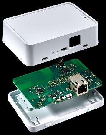
5 2. Software Find the complete source code and an extensive Readme on the software example in Weptech s fork of the Contiki operating system at The Saker is supported as a platform under /platform/saker. The Readme can be found in /platform/saker/readme.md. 3. Board overview The hardware is built upon the following base components: A Texas Instruments CC2538 Cortex - M3 Microcontroller (1) with 512KB Flash + 32KB RAM. The integrated 2.4GHz low power radio is connected to an Inverted F-Antenna (2) (optional U.FL connector (assembly variant)). A Texas Instruments Sub-Ghz Transceiver CC1200 (3) connected to a Monopole PCB Antenna (4) (optional U.FL connector (assembly variant)). The CC1200 is controlled by the CC2538 via SPI. A Microchip E28J60 10BASE-T Ethernet Controller (5) connected to a RJ45 modular jack. The E28J60 is controlled by the CC2538 via SPI (not shared with CC1200). A Microchip 24AA02E48 EEPROM providing a (read-only) EUI-48 ( MAC address ) for the Ethernet Interface. In addition, this EEPROM provides 128Byte of writeable memory which can be used e.g. for configuration purposes. The EEPROM is controlled by the CC2538 via I2C. A FTDI FT234XD USB-to-UART converter (7) providing a virtual COM port to the host system Two buttons Three LEDs WEPTECH elektronik GmbH Page 5 of 19 V.1.0.1
6 Figure 1 Board Overview 4. Power Supply The board is powered using 5V via Micro-USB connector. In the default configuration, this jack is also connected to the FTDI USB-to-UART IC. The maximum current drawn by the board is approximately 220mA at the following conditions: CC2538 running at full speed (32MHz) Ethernet actively transmitting data CC1200 in TX 5. CC USB Interface The internal USB interface of the CC2538 is not used. It can be connected to the USB Micro jack if needed by placing to 0R resistors (R101 and R103, SMD 0603) and removing R100 and R102 (SMD 0402). By the removing the latter two resistors, the FTDI FT234XD is separated from the USB bus and can t be used any more. WEPTECH elektronik GmbH Page 6 of 19 V.1.0.1
, the pin header X200 (not assembled) can be used to monitor the current drawn by the CC2538. 5.")
7 5.2 Current measurements Figure 2 USB selection using two pairs of resistors The supply voltage of the CC2538 is provided by means of a solder jumper. By cutting this solder jumper (located on the bottom side of the PCB), the pin header X200 (not assembled) can be used to monitor the current drawn by the CC Programming Programming of the CC2538 can take place either by Using the CC2538 bootloader or the JTAG interface CC2538 Bootloader via USB Thanks to the FTDI USB-to-UART chip connected to UART0 RX (PA0) and UART0 TX (PA1), a firmware update can take place via USB. If configured accordingly, pressing BTN1 during a system reset will start execution of the bootloader. BTN1 is connected to PA5 using an external pull-up resistor and pulls PA5 low once pressed. Therefore, the bootloader backdoor configuration (found at address 0x0027FFD7) has to be set as following: Bit 4 (Enable): 1 (Enable backdoor function) Bit 3 (Level): 0 (Active low level for selected pin) Bits 0 2 (Pin Number): JTAG Interface A 10-pin fine pitch (0.05 ) pin header (X201) provides JTAG access to the CC2538. Pin 1 is marked with a triangle (top layer). WEPTECH elektronik GmbH Page 7 of 19 V.1.0.1
8 Pin Signal name Description 1 3V3_CC2538 Voltage supply (Sense) 2 JTAG_TMS Test Mode Select 3 GND Ground 4 JTAG_TCK Test Clock 5 GND Ground 6 JTAG_TDO Test Data Out 7-8 JTAG_TDI Test Data In 9 GND Ground detect 10 RESET# System Reset Table 1 CC2538 X201 JTAG pin out WEPTECH elektronik GmbH Page 8 of 19 V.1.0.1

9 Figure 3 Position of JTAG Connector CC2538 Direction Connected via Peripheral Comment Serial Interfac e PA0 I Solder jumper PA1 O Solder jumper FT234XD TXD FT234XD TXD Boot loader UART0 Rx Boot loader UART0 Tx UART0 UART0 PA2-0R not fitted FT234XD RTS# X Availabl e PA3-0R not fitted FT234XD CTS# X PA4-0R not fitted FT234XD CBUS0 X PA5 I BTN1 Boot loader backdoor PA6 I 10k CFG_1 (Solder jumper NO) PA7 I 10k CFG_2 (Solder jumper NO) PB0 O Solder jumper PB1 O Solder jumper PB2 I Solder jumper CC1200 SCLK CC1200 CS# Configuration purposes Configuration purposes SSI0 CC1200 MISO 10k pull down SSI0 X X WEPTECH elektronik GmbH Page 9 of 19 V.1.0.1
10 PB3 I Solder jumper PB4 O Solder jumper CC1200 GPIO0 I2C-EEPROM SCL 2k2 pull up I2C PB5 I/O Solder jumper I2C-EEPROM SDA 2k2 pull up I2C PB6 X201 JTAG TDI (X) 1 PB7 X201 JTAG TDO (X) 1 PC0 O Via 1k5 to USB_P PC1 O 330R LED RED PC2 O 330R LED YELLOW USB pull up (X) 2 PC3 O 330R LED GREEN PC4 O 0R CC1200 RESET# (X) 3 PC5 I 0R not fitted CC1200 GPIO3 X PC6 I Solder jumper PC7 O Solder jumper PD0 O Solder jumper PD1 O Solder jumper PD2 I Solder jumper PD3 O Solder jumper CC1200 GPIO2 CC1200 MOSI E28J60 CS# E28J60 SCLK SSI0 SSI1 E28J60 MISO 10k pull down SSI1 E28J60 MOSI PD4 I 0R E28J60 INT# (X) PD5 O ETH ENABLE E28J60 enable via FETs 1 After programming 2 If internal USB is not used 3 Reset line optional Table 2 CC2538 peripheral connections SSI1 Solder Jumper is depicted below. In contrast to the image below means normally closed, that means the two copper pads are initially connected and have to be separated e.g. using a cutter knife or scalpel. Afterwards, they can be closed again using a drop of solder. WEPTECH elektronik GmbH Page 10 of 19 V.1.0.1
 PB0 CC1200 SCLK Solder jumper + pull")
11 Figure 4 Solder Jumper NO ( normally open ) 6. CC1200 The CC1200 is connected to CC2538 using the following pins: CC2538 Pin Signal name Description Comment PB1 CC1200 CS# Solder jumper + pull up (not fitted) PB0 CC1200 SCLK Solder jumper + pull down (not fitted) PB2 CC1200 MISO Solder jumper + 100k pull down PC7 CC1200 MOSI Solder jumper + pull down (not fitted) PB3 CC1200 GPIO0 Solder jumper PC6 CC1200 GPIO2 Solder jumper PC5 CC1200 GPIO3 Not connected (series resistor, not fitted) PC4 CC1200 RESET# 0R series resistor + pull up (not fitted) Table 3 CC2538/CC1200 connections WEPTECH elektronik GmbH Page 11 of 19 V.1.0.1
, the pin header X300 (not assembled) can be used to monitor the current drawn by the CC1200. 7.")
12 6.1 Current measurements Figure 5 Position of CC1200 The supply voltage of the CC1200 is provided by means of a solder jumper. By cutting this solder jumper (located on the bottom side of the PCB), the pin header X300 (not assembled) can be used to monitor the current drawn by the CC E28J60 Ethernet Controller CC2538 Pin Signal name Description Comment PD0 E28J60 CS# Solder jumper + 100k pull up PD1 E28J60 SCLK Solder jumper + pull down (not fitted) PD2 E28J60 MISO Solder jumper + 100k pull down PD3 E28J60 MOSI Solder jumper + pull down (not fitted) PD4 E28J60 INT# 0R series resistor PD5 ETH_ENABLE Connected to MOSFET circuit Table 4 CC2538/E28J60 connections 7.1 Power-Up A separate (MOSFET) switch is used to turn on / off the voltage supply for the E28J60. Unless the corresponding pin (PD5) is not asserted, nearly no current is drawn by the Ethernet Controller. This WEPTECH elektronik GmbH Page 12 of 19 V.1.0.1
13 solution was chosen in order to improve compliance with the USB specification and avoid currents above 100mA drawn from the USB port before enumeration has completed. 7.2 Current measurements The supply voltage of the E28J60 is provided by means of a solder jumper. By cutting this solder jumper (located on the bottom side of the PCB), the pin header X401 (not assembled) can be used to monitor the current drawn by the E28J60. Figure 6 Position of E28J60 8. I2C EEPROM An I2C-EEPROM (Microchip 24AA02E48) provides a EUI-48 identifier which can be used as a MACaddress for the Ethernet Interface. The EEPROM is controlled by the CC2538 via I2C. Pull up resistors on SDA and SCL are provided allowing a maximum speed of 400kbps. CC2538 Pin Signal name Description Comment PB4 I2C SCL Solder jumper, 2k2 pull up PB5 I2C SDA Solder jumper, 2k2 pull up Table 5 CC2538/I2C EEPROM connections WEPTECH elektronik GmbH Page 13 of 19 V.1.0.1

 PA3 FT234XD CTS# Not connected (series resistor, not fitted) PA4 FT234XD CBUS0 Not connected (series resistor, not fitted) Table")
14 Figure 7 Position of I2C-EEPROM 9. FTDI FT234XD USB-to-Serial converter The USB-to-Serial converter is connected to the CC2538 using the following pins: CC2538 Pin Signal name Description Comment PA0 FT234XD TXD Solder jumper PA1 FT234XD TXD Solder jumper PA2 FT234XD RTS# Not connected (series resistor, not fitted) PA3 FT234XD CTS# Not connected (series resistor, not fitted) PA4 FT234XD CBUS0 Not connected (series resistor, not fitted) Table 6 CC2538/FT234XD connections Figure 8 Position of FT234XD WEPTECH elektronik GmbH Page 14 of 19 V.1.0.1
 Figure 9 Position of Buttons The reset button is connected to the CC2538 nreset pin using a 2k2 series resistor and a 1µF capacitor.")
 This button can be used as a general purpose button.")
15 10. Buttons The board provides two buttons connected to the CC2538: Reset (S100) BTN1 (S101), connected to PA Reset Button (S100) Figure 9 Position of Buttons The reset button is connected to the CC2538 nreset pin using a 2k2 series resistor and a 1µF capacitor. Once pressed, it forces a low level on the nreset pin, this will lead to a system reset Figure 10 CC2538 Reset Circuit General Purpose Button BTN1 (S101) This button can be used as a general purpose button. It is connected to the CC2538 via PA5 and provides an external pull up resistor. In addition, a debouncing circuit is added. WEPTECH elektronik GmbH Page 15 of 19 V.1.0.1
16 Once pressed, the button generates an active low level on the CC2538 s pin. Figure 11 General Purpose Button. BNT1 can be used to execute the bootloader backdoor if configured accordingly (see 5.3.1). 11. LEDs Three LEDs are provided for signaling purposes: A red LED (D100) connected to the CC2538 using PC1 A yellow LED (D101) connected to the CC2538 using PC2 A green LED (D102) connected to the CC2538 using PC3 As the LEDs cathode is directed towards the CC2538, the LEDs are turned on by setting the appropriate pin to a high level. WEPTECH elektronik GmbH Page 16 of 19 V.1.0.1

17 Figure 12 Position of LEDs Figure 13 LEDs WEPTECH elektronik GmbH Page 17 of 19 V.1.0.1
18 12. References (1) Texas Instruments CC2538 Data Sheet (2) Texas Instruments Design Note DN007 (3) Texas Instruments CC1200 Data Sheet (4) Texas Instruments Design Note DN024 (5) Microchip E28J60 Data Sheet (6) Microchip 24AA02E48 Data Sheet (7) FTDI FT234XD Data Sheet WEPTECH elektronik GmbH Page 18 of 19 V.1.0.1
19 WEPTECH elektronik GmbH Ostring 10 D Landau Tel: Fax: Note: The information, instructions and descriptions in this manual refer to the actual operating and service conditions herein. For technical questions, safety notes or technical failure, please contact WEPTECH elektronik GmbH. We reserve the right to technical modifications. WEPTECH elektronik GmbH Page 19 of 19 V.1.0.1
AN10428 UART-SPI Gateway for Philips SPI slave bridges
 UART-SPI Gateway for Philips SPI slave bridges Rev. 01 7 March 2006 Application note Document information Info Keywords Abstract Content UART-SPI Gateway, UART to SPI, RS-232 to SPI The UART-SPI Gateway
XPort Direct+ Integration Guide/Data Sheet
 XPort Direct+ Integration Guide/Data Sheet Part Number 900-524 Revision B December 2007 Patents, Copyright and Trademark 2007, Lantronix. All rights reserved. No part of the contents of this book may be
Arduino Uno. Arduino Uno R3 Front. Arduino Uno R2 Front
 Arduino Uno Arduino Uno R3 Front Arduino Uno R2 Front Arduino Uno SMD Arduino Uno R3 Back Arduino Uno Front Arduino Uno Back Overview The Arduino Uno is a microcontroller board based on the ATmega328 (datasheet).
USB-to-I2C. Ultra Hardware User s Manual.
 USB-to-I2C Ultra Hardware User s Manual https://www.i2ctools.com/ Information provided in this document is solely for use with the USB-to-I2C Ultra product from SB Solutions, Inc. SB Solutions, Inc. reserves
Wireless Sensor Networks. FireFly 2.2 Datasheet
 2.2 Datasheet July 6, 2010 This page intentionally left blank. Contents 1. INTRODUCTION...1 Features...1 Applications...2 2. BLOCK DIAGRAM...3 3. HARDWARE CONNECTIONS...4 Power...5 Header 1 ( UARTS, I2C,
Radiocrafts Embedded Wireless Solutions
 CEF Ultra-Low Power sub-1 GHz Radio Module platform Product Description The RC18x0 Radio Module platforms are a series of compact surface-mounted ultra-low power RF modules based on the CC1310 system-on-chip
Preliminary. PACKAGE - 28-pin MLP (5mm X 5mm) Example Circuit Diagram CP V. 48MHz Oscillator. USB Function Controller 512B EEPROM
 Example Circuit Diagram CP V. 48MHz Oscillator. USB Function Controller 512B EEPROM") Preliminary Single-Chip USB to UART Bridge SINGLE-CHIP USB to UART DATA TRANSFER - Integrated USB Transceiver; No External Resistors Required - Integrated Clock; No External Crystal Required - Integrated
Preliminary Single-Chip USB to UART Bridge SINGLE-CHIP USB to UART DATA TRANSFER - Integrated USB Transceiver; No External Resistors Required - Integrated Clock; No External Crystal Required - Integrated
AppNote-US2400-EVB Low Power 2.4GHz Transceiver
 US2400-EVB for IEEE 802.15.4 Standard Revision History Hardware Revision Date Description of Changes V01 / V02 Sep. 2011 Initial release V03 Dec 2011 Addition 4.1 Evaluation Board Variants and 5.3 Connector
PremierWave 2050 Enterprise Wi-Fi IoT Module Evaluation Kit User Guide
 PremierWave 2050 Enterprise Wi-Fi IoT Module Evaluation Kit User Guide Part Number 900-765-R Revision A February 2016 Intellectual Property 2016 Lantronix, Inc. All rights reserved. No part of the contents
xpico 200 Series Evaluation Kit User Guide
 xpico 200 Series Evaluation Kit User Guide This guide describes how to setup the xpico 200 series evaluation kit and provides the information needed to evaluate the included xpico 240 or xpico 250 embedded
Radiocrafts Embedded Wireless Solutions
 Demonstration Kit User Manual Table of contents TABLE OF CONTENTS... 1 DEMONSTRATION KIT INTRODUCTION... 2 DEMO BOARD INTRODUCTION... 2 BLOCK DIAGRAM... 3 I/O CONNECTION... 4 PROTOTYPING WITH THE RC188XDB...
Hardware Reference. DIL/NetPC DNP/9265 Board Revision 1.0
 DIL/NetPC DNP/9265 Board Revision 1.0 Hardware Reference SSV Embedded Systems Dünenweg 5 D-30419 Hannover Phone: +49 (0)511/40 000-0 Fax: +49 (0)511/40 000-40 E-mail: sales@ssv-embedded.de Document Revision:
USB-to-I2C. Professional Hardware User s Manual.
 USB-to-I2C Professional Hardware User s Manual https://www.i2ctools.com/ Information provided in this document is solely for use with the USB-to-I2C Professional product from SB Solutions, Inc. SB Solutions,
Almond - Datasheet November 2015
 Robotic Hand Development Board Features 6 Bidirectional Motor control USB Programming (with Bootloader) Arduino IDE Compatible Compatible with Firgelli PQ12 -P Actuators Atmel Atmega2560 Microcontroller
U4DIL. AVR USB Module. Rev. 1.1 Documentation Rev. 19. Reusch Elektronik Reusch Elektronik, Dipl.-Ing. (FH) Rainer Reusch
 Rainer Reusch") AVR USB Module Documentation Rev. 19 2010, Dipl.-Ing. (FH) Rainer Reusch www.reusch-elektronik.de http://products.reworld.eu/u4dil.htm File: _Manual Created: 2010-02-10 Changed: 2010-09-07 Contents 1.
AVR USB Module Documentation Rev. 19 2010, Dipl.-Ing. (FH) Rainer Reusch www.reusch-elektronik.de http://products.reworld.eu/u4dil.htm File: _Manual Created: 2010-02-10 Changed: 2010-09-07 Contents 1.
PCB-STM32-F3U. Development baseboard for the STMicro Discovery-F3 module (STMicro part# STM32F3DISCOVERY)
") PCB-STM32-F3U Development baseboard for the STMicro Discovery-F3 module (STMicro part# STM32F3DISCOVERY) Part Number: PCB-STM32-F3U (unpopulated PCB with Discovery module sockets, no other parts) STM32-F3U
PCB-STM32-F3U Development baseboard for the STMicro Discovery-F3 module (STMicro part# STM32F3DISCOVERY) Part Number: PCB-STM32-F3U (unpopulated PCB with Discovery module sockets, no other parts) STM32-F3U
Centipede. Datasheet. Centipede is QCA AR9331 SoC based DIP platform with an integrated 2.4 GHz N (1x1) radio
 radio") is QCA AR9331 SoC based DIP platform with an integrated 2.4 GHz (1x1) radio Its tiny form factor (22 x 60 mm), integrated RJ-45, an on-board omni-directional chip antenna and "breadboardable" layout allows
is QCA AR9331 SoC based DIP platform with an integrated 2.4 GHz (1x1) radio Its tiny form factor (22 x 60 mm), integrated RJ-45, an on-board omni-directional chip antenna and "breadboardable" layout allows
Ultratronics v1.0 DATASHEET
 Ultratronics v1.0 DATASHEET Author Bart Meijer Date November 21 st, 2017 Document version 1.2 Ultratronics Datasheet Reprapworld.com 1 PRODUCT OVERVIEW Ultratronics is the latest development in 3D printer
ARDUINO UNO REV3 SMD Code: A The board everybody gets started with, based on the ATmega328 (SMD).
.") ARDUINO UNO REV3 SMD Code: A000073 The board everybody gets started with, based on the ATmega328 (SMD). The Arduino Uno SMD R3 is a microcontroller board based on the ATmega328. It has 14 digital input/output
ARDUINO UNO REV3 SMD Code: A000073 The board everybody gets started with, based on the ATmega328 (SMD). The Arduino Uno SMD R3 is a microcontroller board based on the ATmega328. It has 14 digital input/output
ARDUINO MEGA 2560 REV3 Code: A000067
 ARDUINO MEGA 2560 REV3 Code: A000067 The MEGA 2560 is designed for more complex projects. With 54 digital I/O pins, 16 analog inputs and a larger space for your sketch it is the recommended board for 3D
Win-I2CUSB Hardware User s Manual
 Win-I2CUSB Hardware User s Manual http://www.demoboard.com Information provided in this document is solely for use with the Win-I2CUSB product from The Boardshop. The Boardshop and SB Solutions, Inc. reserve
U2DIL. AVR USB Module. Rev. 1.1 Documentation Rev. 37. Reusch Elektronik Reusch Elektronik, Dipl.-Ing. (FH) Rainer Reusch
 Rainer Reusch") AVR USB Module Rev. 1.1 Documentation Rev. 37 Reusch Elektronik 2010 Reusch Elektronik, Dipl.-Ing. (FH) Rainer Reusch www.reusch-elektronik.de http://products.reworld.eu/u2dil.htm File: _Manual Created:
AVR USB Module Rev. 1.1 Documentation Rev. 37 Reusch Elektronik 2010 Reusch Elektronik, Dipl.-Ing. (FH) Rainer Reusch www.reusch-elektronik.de http://products.reworld.eu/u2dil.htm File: _Manual Created:
User's hardware guide RSS2 sensor board Model S2 Rev 2.4
 Document version 0.9 User's hardware guide RSS2 sensor board Model S2 Rev 2.4 Page 1 Table of Contents Manifesto...3 The Universal IEEE 802.15.4 Sensor for WSN and IoT applications...3 This document...3
Product Datasheet: DWM1001-DEV DWM1001 Module Development Board. Key Features and Benefits
 Product Datasheet: DWM1001-DEV DWM1001 Module Development Board Plug-and-Play Development Board for evaluating the performance of the Decawave DWM1001 module Easily assemble a fully wireless RTLS system,
ConnectCore for i.mx6ul Starter Board. Hardware Reference Manual
 ConnectCore for i.mx6ul Starter Board Hardware Reference Manual Revision history 90001520 Revision Date Description 01 October 2016 Alpha release Trademarks and copyright Digi, Digi International, and
U6DIL. AVR USB Module. Rev. 1.1 Documentation Rev. 18. Reusch Elektronik Reusch Elektronik, Dipl.-Ing. (FH) Rainer Reusch
 Rainer Reusch") AVR USB Module Documentation Rev. 18 2011, Dipl.-Ing. (FH) Rainer Reusch www.reusch-elektronik.de http://products.reworld.eu/u6dil.htm File: _Manual Created: 2011-02-22 Changed: 2011-03-31 Table of Contents
AVR USB Module Documentation Rev. 18 2011, Dipl.-Ing. (FH) Rainer Reusch www.reusch-elektronik.de http://products.reworld.eu/u6dil.htm File: _Manual Created: 2011-02-22 Changed: 2011-03-31 Table of Contents
KSZ9692PB User Guide Brief
 KSZ9692PB User Guide Brief KSZ9692PB Evaluation Platform Rev 2.0 General Description The KSZ9692PB Evaluation Platform accelerates product time-to-market by providing a hardware platform for proof-of-concept,
Product Overview: DWM1001-DEV DWM1001 Module Development Board. Key Features and Benefits
 Product Overview: DWM1001-DEV DWM1001 Module Development Board Plug-and-Play Development Board for evaluating the performance of the Decawave DWM1001 module Easily assemble a fully wireless RTLS system,
USB-to-I2C Basic. Hardware User s Manual.
 USB-to-I2C Basic Hardware User s Manual http://www.i2ctools.com/ Information provided in this document is solely for use with the USB-to-I2C product from SB Solutions, Inc. SB Solutions, Inc. reserves
WiMOD - ic880a. Application Note AN014 / Version 1.3. USB modifications for direct SPI operation. Document ID: 4000/40140/0079
 WiMOD - ic880a Application Note AN014 / Version 1.3 USB modifications for direct SPI operation Document ID: 4000/40140/0079 IMST GmbH Carl-Friedrich-Gauss-Str. 2-4 D-47475 Kamp-Lintfort Overview Document
keyestudio Keyestudio MEGA 2560 R3 Board
 Keyestudio MEGA 2560 R3 Board Introduction: Keyestudio Mega 2560 R3 is a microcontroller board based on the ATMEGA2560-16AU, fully compatible with ARDUINO MEGA 2560 REV3. It has 54 digital input/output
Please refer to "4. Evaluation Board" on page 2 for more information about these steps. Figure 1. System Connections
 CP2120 EVALUATION KIT USER S GUIDE 1. Kit Contents The CP2120 Evaluation Kit contains a CP2120 evaluation board and a power supply. The following supporting documents can be downloaded from www.silabs.com:
ConnectCore 6UL SBC Express. Hardware Reference Manual
 ConnectCore 6UL SBC Express Hardware Reference Manual Revision history 90001520 Revision Date Description 01 October 2016 Alpha release A June 2017 Modified regulatory and certification information as
This manual provides information for the final user application developer on how to use SPC57S-Discovery microcontroller evaluation board.
 User manual SPC570S-DISP: Discovery+ Evaluation Board Introduction This manual provides information for the final user application developer on how to use SPC57S-Discovery microcontroller evaluation board.
Prototyping Module Datasheet
 Prototyping Module Datasheet Part Numbers: MPROTO100 rev 002 Zenseio LLC Updated: September 2016 Table of Contents Table of Contents Functional description PROTOTYPING MODULE OVERVIEW FEATURES BLOCK DIAGRAM
Product Specification
 Product Specification Features Amp ed RF, Inc. Description 15mm x 27mm The added class 1 power, +18dBm, of the BT-11, gives this module one of the best ranges in the industry. It s completely pin compatible
ARDUINO UNO REV3 Code: A000066
 ARDUINO UNO REV3 Code: A000066 The UNO is the best board to get started with electronics and coding. If this is your first experience tinkering with the platform, the UNO is the most robust board you can
HZX N03 Bluetooth 4.0 Low Energy Module Datasheet
 HZX-51822-16N03 Bluetooth 4.0 Low Energy Module Datasheet SHEN ZHEN HUAZHIXIN TECHNOLOGY LTD 2017.7 NAME : Bluetooth 4.0 Low Energy Module MODEL NO. : HZX-51822-16N03 VERSION : V1.0 1.Revision History
ARDUINO MEGA ADK REV3 Code: A000069
 ARDUINO MEGA ADK REV3 Code: A000069 OVERVIEW The Arduino MEGA ADK is a microcontroller board based on the ATmega2560. It has a USB host interface to connect with Android based phones, based on the MAX3421e
DEVBOARD3 DATASHEET. 10Mbits Ethernet & SD card Development Board PIC18F67J60 MICROCHIP
 DEVBOARD3 DATASHEET 10Mbits Ethernet & SD card PIC18F67J60 MICROCHIP Version 1.0 - March 2009 DEVBOARD3 Version 1.0 March 2009 Page 1 of 7 The DEVBOARD3 is a proto-typing board used to quickly and easily
ESPino - Specifications
 ESPino - Specifications Summary Microcontroller ESP8266 (32-bit RISC) WiFi 802.11 (station, access point, P2P) Operating Voltage 3.3V Input Voltage 4.4-15V Digital I/O Pins 9 Analog Input Pins 1 (10-bit
Pmod modules are powered by the host via the interface s power and ground pins.
 1300 Henley Court Pullman, WA 99163 509.334.6306 www.store. digilent.com Digilent Pmod Interface Specification 1.2.0 Revised October 5, 2017 1 Introduction The Digilent Pmod interface is used to connect
RFID Reader Board 13.56MHz RFID Transceiver MLX90132
 Table of Contents 1. General Description... 2 1.1 Connector X1 (SPI/ UART Communication)... 2 2. MLX90132 Pin Definitions & Descriptions... 3 2.1 MLX90132 simplified Block Diagram... 3 3. RFID90132 Circuit
Radiocrafts Embedded Wireless Solutions
 Ultra-Low Power Dual Band Radio Module Platform Product Description The Radio Module is a dual band (sub 1-GHz and 2.4 GHz) compact surfacemounted ultra-low power RF module based on the CC1350 system-on-chip
Future Technology Devices International Limited
 Future Technology Devices International Limited Datasheet LC234X Development Module 1 Introduction The LC234X module is a low cost USB to serial UART bridge using the FTDI FT234XD. In addition to the 4
Hardware Reference. DIL/NetPC DNP/2110 Board Revision 1.0
 DIL/NetPC DNP/2110 Board Revision 1.0 Hardware Reference SSV Embedded Systems Heisterbergallee 72 D-30453 Hannover Phone +49-(0)511-40000-0 Fax +49-(0)511-40000-40 E-mail: sales@ist1.de Manual Revision:
Teratronik elektronische systeme gmbh. V4½-CPU Technical Data. Date:
 Teratronik elektronische systeme gmbh Technical Data Date: 2008-11-26 Table of contents 1. 2. 3. 3.1 3.2 3.3 3.4 3.5 3.6 3.7 3.8 4. 4.1 4.2 4.3 4.4 Features...3 Views...4 Connector pinouts...6 J1 - board-to-board
PAN1740 Design Guide
 1 of 14 PAN1740 2 of 14 TABLE OF CONTENTS 1. Scope of this Document... 3 2. Key benefits when using PAN1740... 3 3. Bluetooth Low Energy... 3 4. Description PAN1740... 4 5. Block Diagram PAN1740 Module...
A1/B1 EB v2.0 User Manual V1.1 05/10/2017
 A1/B1 EB v2.0 User Manual V1.1 05/10/2017 Table of Contents 1. Device Overview...2 2. Electrical Characteristics...3 2.1 Test Conditions... 3 2.2 Absolute Maximum Ratings... 3 2.3 Operating Conditions...
eip-10 Embedded TCP/IP 10-BaseT Network Module Features Description Applications
 Embedded TCP/IP 10-BaseT Network Module Features 8-bit reprogrammable Microcontroller with Enhanced Flash program memory, EEPROM and Static RAM data memory On board 10Mbps Ethernet controller, and RJ45
Microcontroller. BV523 32bit Microcontroller. Product specification. Jun 2011 V0.a. ByVac Page 1 of 8
 32bit Product specification Jun 2011 V0.a ByVac Page 1 of 8 Contents 1. Introduction...3 2. Features...3 3. Physical Specification...3 3.1. PIC32...3 3.2. USB Interface...3 3.3. Power Supply...4 3.4. Power
Future Technology Devices International
 Future Technology Devices International Datasheet UMFT234XD Breakout Modules 1 Introduction UMFT234XD is a USB to UART breakout module The UMFT234XD breakout module utilizes FTDI s FT234XD IC to convert
ARDUINO YÚN MINI Code: A000108
 ARDUINO YÚN MINI Code: A000108 The Arduino Yún Mini is a compact version of the Arduino YUN OVERVIEW: Arduino Yún Mini is a breadboard PCB developed with ATmega 32u4 MCU and QCA MIPS 24K SoC CPU operating
Arduino Diecimila Pinouts 697B B8D-A50A-61944C26074F
 mightwerk Resources for creators and innovators outs 697B1380-9797-4B8D-A50A-61944C26074F Introduction... 1 4-pin Expansion Header out... 2 6-pin ICSP Header out... 3 Map from to... 4 Map from ATmega328
CSCI 6907 PROJECT PROPOSAL LIGHTS OUT MANAGEMENT
 CSCI 6907 PROJECT PROPOSAL LIGHTS OUT MANAGEMENT JAMES LEE JAMESLEE@GWU.EDU. Project Abstract I am a system administrator who manages hundreds of Unix systems. One of the essential tools to ensure I don
RN-174. WiFly GSX Super Module. Features. Description. Applications. rn-174-ds v1.1 1/24/2011
 www.rovingnetworks.com rn-174-ds v1.1 1/24/2011 WiFly GSX Super Module Features Development board containing the RN-171 module, status LEDs, power regulator Supports chip antenna (-C), PCB Trace antenna
ATtiny104 Xplained Nano. Preface. AVR 8-bit Microcontrollers USER GUIDE
 AVR 8-bit Microcontrollers ATtiny104 Xplained Nano USER GUIDE Preface The Atmel ATtiny104 Xplained Nano evaluation kit is a hardware platform to evaluate the ATtiny104 microcontroller. Supported by the
DE-10 Super Expansion Board
 www.cbmstuff.com DE-10 Super Expansion Board For Terasic DE-10 Nano FPGA boards Assembly & Technical Information Manual Manual v1.0 Release Date: December 31,2018 Last Revision: January 3, 2018 All material
Arduino ADK Rev.3 Board A000069
 Arduino ADK Rev.3 Board A000069 Overview The Arduino ADK is a microcontroller board based on the ATmega2560 (datasheet). It has a USB host interface to connect with Android based phones, based on the MAX3421e
Future Technology Devices International Ltd
 Future Technology Devices International Ltd Datasheet UMFT200XD Breakout Modules 1 Introduction UMFT200XD is a USB to I 2 C breakout module The UMFT200XD breakout module utilizes FTDI s FT200XD IC to convert
nrf24lu1+ Development Kit
 nrf24lu1+ Development Kit User Guide v1.1 All rights reserved. Reproduction in whole or in part is prohibited without the prior written permission of the copyright holder. 2012-4-27 Liability disclaimer
AT02667: XMEGA-E5 Xplained Hardware User's Guide. Features. Description. AVR XMEGA Microcontrollers APPLICATION NOTE
 AVR XMEGA Microcontrollers AT02667: XMEGA-E5 Xplained Hardware User's Guide APPLICATION NOTE Features Atmel AVR ATxmega32E5 microcontroller OLED display with 128 32 pixels resolution Ambient light sensor
UM2461 User manual. SPC584B-DIS Discovery Board. Introduction
 User manual SPC584B-DIS Discovery Board Introduction The SPC584B-DIS is a low-cost development board to evaluate and develop applications with the microcontroller SPC584B70E1 in etqfp 64-pin package. This
ARDUINO LEONARDO ETH Code: A000022
 ARDUINO LEONARDO ETH Code: A000022 All the fun of a Leonardo, plus an Ethernet port to extend your project to the IoT world. You can control sensors and actuators via the internet as a client or server.
Ethernet1 Xplained Pro
 Ethernet1 Xplained Pro Part Number: ATETHERNET1-XPRO The Atmel Ethernet1 Xplained Pro is an extension board to the Atmel Xplained Pro evaluation platform. The board enables the user to experiment with
UNC20 Module. User's Manual. D Breisach, Germany D Breisach, Germany Fax +49 (7667)
") UNC20 Module User's Manual P.O: Box 1103 Kueferstrasse 8 Tel. +49 (7667) 908-0 sales@fsforth.de D-79200 Breisach, Germany D-79206 Breisach, Germany Fax +49 (7667) 908-200 http://www.fsforth.de Copyright
UNC20 Module User's Manual P.O: Box 1103 Kueferstrasse 8 Tel. +49 (7667) 908-0 sales@fsforth.de D-79200 Breisach, Germany D-79206 Breisach, Germany Fax +49 (7667) 908-200 http://www.fsforth.de Copyright
TTL-234X. TTL234X Series Range of Cables. Datasheet
 Future Technology Devices International Ltd TTL-234X TTL234X Series Range of Cables Datasheet Document Reference No.: FT_001394 Issue Date: 2017-02-22 Future Technology Devices International Limited (FTDI)
Digital Circuits Part 2 - Communication
 Introductory Medical Device Prototyping Digital Circuits Part 2 - Communication, http://saliterman.umn.edu/ Department of Biomedical Engineering, University of Minnesota Topics Microcontrollers Memory
AARDVARK. Level Shifter Board. Level Shifter Board. Datasheet v1.00 February 15, 2008 I 2 C/SPI. Features
 Level Shifter Board AARDVARK I 2 C/SPI Features Level shifting of I 2 C, SPI, and MDIO signals from 1.2 V to 3.3 V I 2 C speeds of up to 800 khz SPI and MDIO speeds of up to 20 MHz Powering downstream
USB UART 4 click PID: MIKROE Weight: 23 g
 USB UART 4 click PID: MIKROE-2810 Weight: 23 g USB UART 4 click features well-known FT232RL USB-to-UART interface module from FDTI. It provides USB to asynchronous serial data transfer interface, allowing
Part Number: PCB-STM32-F4B1 (unpopulated PCB with Discovery module sockets, no other parts) STM32-F4B1 (assembled board, not presently available)
 STM32-F4B1 (assembled board, not presently available)") PCB-STM32-F4B1 Development baseboard for the STMicro Discovery-F4 module (STMicro part# STM32F4DISCOVERY) PCB Rev 1.00 shown. PCB Rev 1.20 has on-board RS232 drivers. Part Number: PCB-STM32-F4B1 (unpopulated
PCB-STM32-F4B1 Development baseboard for the STMicro Discovery-F4 module (STMicro part# STM32F4DISCOVERY) PCB Rev 1.00 shown. PCB Rev 1.20 has on-board RS232 drivers. Part Number: PCB-STM32-F4B1 (unpopulated
SSI-USB-DUO. Flexible Embedded Platform. Brief English Version
 SSI-USB-DUO Brief English Version Seite 1/7 SSI-USB-DUO Flexible Embedded Platform Brief English Version Hardware v1.0 Dokument: 1401171103 SSI-USB-DUO Brief English Version Seite 2/7 1 Preface The SSI-USB-DUO-module
Kinetis K70 System-On-Module (SOM) Baseboard Hardware Architecture
 Baseboard Hardware Architecture") Kinetis K70 System-On-Module (SOM) Baseboard Version 1.0 Table of Contents 1. OVERVIEW...3 2. REFERENCES...3 3. HARDWARE PLATFORM...3 3.1. OVERVIEW...3 3.2. FUNCTIONAL BLOCK DIAGRAM...4 3.3. SOM CONNECTORS...4
Kinetis K70 System-On-Module (SOM) Baseboard Version 1.0 Table of Contents 1. OVERVIEW...3 2. REFERENCES...3 3. HARDWARE PLATFORM...3 3.1. OVERVIEW...3 3.2. FUNCTIONAL BLOCK DIAGRAM...4 3.3. SOM CONNECTORS...4
TTL-232R-PCB. TTL to USB Serial Converter PCB. Datasheet
 Future Technology Devices International Ltd TTL-232R-PCB TTL to USB Serial Converter PCB Datasheet Document Reference No.: FT_000065 Version 1.0 Issue Date: 2008-08-28 Future Technology Devices International
AC/DC. Adapter. Ribbon. Cable Serial. Serial. Adapter. Figure 1. Hardware Setup using an EC2 Serial Adapter
 C8051F32X DEVELOPMENT KIT USER S GUIDE 1. Kit Contents The C8051F32x Development Kit contains the following items: C8051F320 Target Board C8051Fxxx Development Kit Quick-Start Guide C8051F32x Development
3.3V regulator. JA H-bridge. Doc: page 1 of 7
 Digilent Cerebot Board Reference Manual Revision: 11/17/2005 www.digilentinc.com 215 E Main Suite D Pullman, WA 99163 (509) 334 6306 Voice and Fax Overview The Digilent Cerebot Board is a useful tool for
GWBMA0x Bluetooth Audio module
 GWBMA0x Bluetooth Audio module Data sheet version 0.9 draft GWBMA0X DATASHEET 0.9 GIGAWIT 1 Introduction GWBMA1X is a high performance Bluetooth audio module, It provides various type of wireless audio
EZ-USB FX3 Development Kit Guide
 CYUSB3KIT-001 EZ-USB FX3 Development Kit Guide Doc. #: 001-70237 Rev. *A Cypress Semiconductor 198 Champion Court San Jose, CA 95134-1709 Phone (USA): 800.858.1810 Phone (Intnl): 408.943.2600 http://www.cypress.com
BT 31 Data Sheet. Amp ed RF Technology Inc.
 BT 31 Data Sheet Amp ed RF Technology Inc. Product Specification BT31 Features Bluetooth features FCC&Bluetooth licensed radio Bluetooth v3.0 Class 1 radio Range up to 100m LOS 1.5Mbps data throughput
USB Debug Adapter. Power USB DEBUG ADAPTER. Silicon Laboratories. Stop. Run. Figure 1. Hardware Setup using a USB Debug Adapter
 C8051F38X DEVELOPMENT KIT USER S GUIDE 1. Kit Contents The C8051F38x Development Kit contains the following items: C8051F380 Target Board C8051Fxxx Development Kit Quick-start Guide Silicon Laboratories
GW-USB-06. User s Guide. IQRF USB Gateway. FW v MICRORISC s.r.o. User_Guide_GW-USB-06_ Page 1
 FW v1.04 IQRF USB Gateway User s Guide 2016 MICRORISC s.r.o. www.iqrf.org User_Guide_GW-USB-06_160122 Page 1 Description GW-USB-06 is an IQRF gateway with USB connectivity. It is intended as an interface
Revision History. Version Date Changes Error in PIN description SPI jack Initial version
 MANUAL ANAGATE SPI ANALYTICA GmbH Vorholzstrasse 36 Tel. +49 721 35043-0 E-mail: info@analytica-gmbh.de D-76137 Karlsruhe Fax: +49 721 35043-20 WWW: http://www.analytica-gmbh.de 1 2004-2006, Analytica
Creator Ci40 product brief
 Creator Ci40 is a high-performance, low-power IoT hub that packs Ethernet, Wi-Fi, 802.11b/g/n/ac, Bluetooth Classic and Low Energy and an 802.15.4 radio onto a powerful IoT gateway with expansion ports
QS Series Master Development System User's Guide
 QS Series Master Development System User's Guide ! Table of Contents Warning: Some customers may want Linx radio frequency ( RF ) products to control machinery or devices remotely, including machinery
Future Technology Devices International Ltd
 Future Technology Devices International Ltd Datasheet UM232H-B USB to Serial/Parallel Break-Out Module UM232H-B Datasheet UM232H-B is a multiple-interface Hi-Speed USB to UART, 245 FIFO, FT1248, I 2 C,
Zefeer EVB-L. Hardware Manual
 DATE CREATION: Nov 2004 DATE LAST MODIFIED: May 2007 DAVE s.r.l. VERSION: 1.0.1 www.dave.eu FILE NAME: Zefeer-evb-l-hm Zefeer EVB-L Hardware Manual History Rev. Date EVB-L Hw Rev. DZB Hw Rev. Details 0.9.0
February 28,
 February 28, 2014 1 http://www.mattairtech.com/ Table of Contents Overview...3 Introduction...3 Features...4 Hardware...5 Main Header Pins...5 ISP Header Pins...6 Solder Jumpers...6 Onboard 3.3V, 250mA
Hardware Manual RM CANview
 Hardware Manual RM CANview 1998-2005 RM Michaelides Software & Elektronik GmbH Donaustraße 14 D-36043 Fulda Germany cv_hw_e.doc Table of Contents 1 Legal Regulations...3 2 About the CANview...4 3 Important
Preliminary MK-CY-043. Data Sheet. Amulet Capacitive 4.3 GEMmodule. Introduction:
 Introduction: Amulet Capacitive 4.3 GEMmodule Data Sheet Preliminary The is a 4.3 fully integrated, production ready color module with smartphone-like features. Using Cypress TrueTouch technology, this
Cookie User Manual. For NuMicro Edition 1.0. Rev. 1.0 Release: forum.coocox.org.
 Cookie User Manual For NuMicro Edition 1.0 Rev. 1.0 Release: 2012-08-09 Website: Forum: Techinal: Market: www.coocox.org forum.coocox.org master@coocox.com market@coocox.com 1 Introduction Cookie is an
Hardware Manual RM CANview Gateway
 Hardware Manual RM CANview Gateway 2008 RM Michaelides Software & Elektronik GmbH Donaustraße 14 D-36043 Fulda Germany cvgateway-hw-e.doc Table Of Contents 1 Legal Regulations... 3 2 About the CANview
Documentation for SCSI PCMCIA drive SCSI controller hardware V2.0 PCMCIA slot hardware V1.1
 Documentation for SCSI PCMCIA drive SCSI controller hardware V2.0 PCMCIA slot hardware V1.1 2006 06 24 / Michael Bäuerle Preamble The goal of this project is a PCMCIA drive
Wireless Modules Wi-Fi Module
 based on TI CC3200 IoT based on CC3200 Texas Instrument chip. The module is the second-generation series of modules in the SimpleLink family and consists of an applications microcontroller unit (MCU),
Lima (-I) Data sheet. Lima has N 2x2 radio supporting up to 300 Mbps data-rate and comes in two versions: commercial or industrial temperature
 Data sheet. Lima has N 2x2 radio supporting up to 300 Mbps data-rate and comes in two versions: commercial or industrial temperature") (-I) has 802.11N 2x2 radio supporting up to 300 Mbps data-rate and comes in two versions: commercial or industrial temperature is a QCA 4531 chipset based module with a 650 MHz CPU and 802.11N 2x2 (MIMO)
(-I) has 802.11N 2x2 radio supporting up to 300 Mbps data-rate and comes in two versions: commercial or industrial temperature is a QCA 4531 chipset based module with a 650 MHz CPU and 802.11N 2x2 (MIMO)
ATmega324PB Xplained Pro. Preface. AVR 8-bit Microcontrollers USER GUIDE
 AVR 8-bit Microcontrollers ATmega324PB Xplained Pro USER GUIDE Preface The Atmel ATmega324PB Xplained Pro evaluation kit is a hardware platform to evaluate the ATmega324PB microcontroller. Supported by
USER GUIDE. ATWINC1500 Xplained Pro. Preface
 USER GUIDE ATWINC1500 Xplained Pro Preface Atmel ATWINC1500 Xplained Pro is an extension board to the Atmel Xplained Pro evaluation platform. The extension board allows to evaluate the Atmel ATWINC1510/1500
Skywire BeagleBone Black Cape Data Sheet
 Skywire BeagleBone Black Cape Data Sheet NimbeLink Corp Updated: January 2018 PN 30122 rev 2 NimbeLink Corp. 2016. All rights reserved. 1 Table of Contents Table of Contents 2 Introduction 3 Overview 3
CPU369-Module Documentation. Fujitsu Microelectronics Europe GmbH Am Siebenstein Dreieich-Buchschlag, Germany
 CPU369-Module Documentation Fujitsu Microelectronics Europe GmbH Am Siebenstein 6-10 63303 Dreieich-Buchschlag, Germany History Revision Date Comment V1.0 08.03.01 New Document V1.1 17.10.03 Modifications
WiMOD - im880b. Application Note AN017 / Version 1.1. Firmware Update for im880b. Document ID: 4100/40140/0103. Category:
 WiMOD - im880b Application Note AN017 / Version 1.1 Firmware Update for im880b Document ID: 4100/40140/0103 Category: IMST GmbH Carl-Friedrich-Gauss-Str. 2-4 D-47475 Kamp-Lintfort Overview Document Information
Carambola2 (-I) Data sheet. Carambola2 is a tiny surface mountable 2.4 GHz Wi-Fi module running OpenWRT linux software
 Data sheet. Carambola2 is a tiny surface mountable 2.4 GHz Wi-Fi module running OpenWRT linux software") (-I) is a tiny surface mountable 2.4 GHz Wi-Fi module running OpenWRT linux software 8devices is a member of Carambola wireless modules family and is based on Qualcomm/Atheros AR9331 SoC. is a surface
(-I) is a tiny surface mountable 2.4 GHz Wi-Fi module running OpenWRT linux software 8devices is a member of Carambola wireless modules family and is based on Qualcomm/Atheros AR9331 SoC. is a surface