Troubleshooting a K40 Laser Power Subsystem
|
|
|
- Antonia Ross
- 5 years ago
- Views:
Transcription

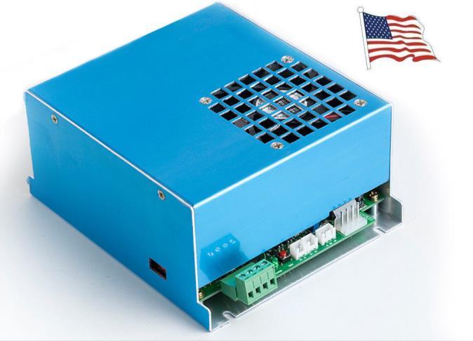
1 Troubleshooting a K40 Laser Power Subsystem
 do not make any warranties about the completeness, reliability and accuracy of this information.")
2 This work is licensed under a Creative Commons Attribution-onCommercial 4.0 International License. The author(s) do not make any warranties about the completeness, reliability and accuracy of this information. Any action you take upon the information in this document is strictly at your own risk, and the author will not be held liable for any losses and damages in connection with the use of this information.
3 Symbol Key These symbols are used in this document to designate a functions as described below = the O path in a flow? = a connector to another flow Y = a YES path in a flow? = A test procedure used in a flow


4 Preparation: Make a safe environment When the beam is or may be present: Ensure all covers & interlocks are engaged Wear your laser eye protection Turn O the power to the machine Is the green LED on the LPS illuminated? ote: some LED s may be red. The LPS is not getting AC power or it has an internal failure A Y Proceed to B


5 Testing Methods Testing the AC Input: A Use this table and test method to test for the correct ACV AC AC AC from mains AC from mains Caution: Read HIGH VOLTAGE with DVM on AC voltage scale across these pins G Ground With DVM on volts scale read to ground 0vdc L- Laser cathode return DO OT MEASURE. Depends on country ( VAC) P or Q Is the proper AC voltage present? Y You said the green LED was not illuminated on the LPS. That got you here. The correct VAC is present at the LPS therefore something is internally wrong with your LPS. I Check: The wiring from the K40 main AC socket to the LPS AC connections The fuse located in the input plugs receptacle could be blown. Power at the wall plug could be wrong or missing. Shown is US power. Your plugs may be different.


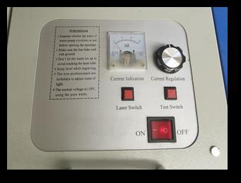
6 Initial Tests: B When you push the Test button down on the LPS does the laser fire? Something is wrong with your LPS. I Y Insure all interlocks are closed Interlocks may be: Covers Water flow switch Over temp switch At the control panel Engage the Laser Switch When you push the Test Switch button on the control panel does the laser fire? Something is wrong with the control panel its wiring, the laser or the LPS D Y Your laser is MAUALLY operating properly. Test the programmatic operation of your machine. K

7 Connectors from right to left Troubleshooting white connector Control Panel s connection to the LPS D Do the connectors on your LPS look like this? Y Perform the tests in the table below Go to F Signal Function Test Procedure Correct Reading L 5V Laser fire from controller 5vdc to controller Touch this pin to ground and the laser will fire if the LASER SWITCH is on. With DVM on volts scale read to ground Laser fires 5vdc G Ground With DVM on volts scale read to ground 0VDC 24V 24vdc to controller With DVM on volts scale read to ground 24vdc 5V 5vdc to pot With DVM on volts scale read to ground 5vdc I Analog power With DVM on volts scale read to ground. Voltage varies as pot is turned 0-5vdc G Ground With DVM on volts scale read to ground. 0vdc K+ Laser Test Button Push & Hold Laser Test Button & measure with DVM on volts scale to ground. K- Laser Switch With switch On reads on volts scale with DVM to ground 0vdc 0vdc G Ground With DVM on volts scale read with to ground 0vdc P+ Laser On With Laser On switch O on volts scale with DVM read to ground Ovdc AC AC AC from mains AC from mains Caution: Read HIGH VOLTAGE with DVM on AC voltage scale across these pins G Ground With DVM on volts scale read to ground 0vdc L- Laser cathode return DO OT MEASURE. Depends on country ( VAC) H


8 Connectors from right to left Troubleshooting green connector control panel s connection to the LPS F Do the connectors on your LPS look like this? Y Perform the tests in the table below Go to G Signal Function Test Procedure Correct Reading L 5V Laser fire from controller 5vdc to controller Touch this pin to ground and the laser will fire if the LASER SWITCH is on. With DVM on volts scale read to ground Laser fires 5vdc G Ground With DVM on volts scale read to ground 0VDC 24V 24vdc to controller With DVM on volts scale read to ground 24vdc 5V 5vdc to pot With DVM on volts scale read to ground 5vdc I Analog power With DVM on volts scale read to ground. Voltage varies as pot is turned 0-5vdc G Ground With DVM on volts scale read to ground. 0vdc L Test Switch Push & Hold Laser Test Switch & measure with DVM on volts scale to ground. P Laser Switch With switch On reads on volts scale with DVM to ground 0vdc 0vdc G Ground With DVM on volts scale read with to ground 0vdc AC AC AC from mains AC from mains Caution: Read HIGH VOLTAGE with DVM on AC voltage scale across these pins G Ground With DVM on volts scale read to ground 0vdc L- Laser cathode return DO OT MEASURE. Depends on country ( VAC) Proceed to H
9 Testing Methods After you measure you LPS inputs H If one or more of the voltages are incorrect, the table below provides more things to try. The tables below are organized by function. In all cases trace and verify the wiring and all connections back to the source of the FUCTIO. Signal Function Further Checks Go to L Laser fire from controller If this test fails and the laser does not fire while running a job the problem is likely the controllers output 5V 5vdc Any time 5V is incorrect your LPS is not operating correctly G Ground Any time ground is not 0V its likely there is a ground connection missing 24V 24vdc If 24V is not correct its likely from a fault in the supply. K Go to test procedure Check wiring Go to test procedure O O I Analog power If the voltage is not changing with pot position check the wiring and/or test/replace the pot L L Test Switch Check the wiring and test the switch M P Laser Switch Check the wiring and test the switch M AC AC AC from mains AC from mains Check the input power and the main fuse located in the plugs housing I P Q L- Laser cathode return DO OT MEASURE. If voltages are OK and problem not fixed, try? I R


.")
10 Troubleshooting Your LPS: I If you have landed here its possible that your LPS is bad (:. Here are some additional checks Generally speaking the LPS is not a repairable item but here are some addition checks to be sure it should be replaced. Check each of these and correct them if they are incorrect. Then retest to see if the supply works. Turnoff the machine Unplug the machine Unplug the leftmost connector on the LPS. On the left side of the LPS, verify that you have this switch in the correct position for the mains voltage you are using If not set it correctly Remove the LPS cover On the PCB check this fuse to see if it is blown by using me procedure (). You can replace the fuse but most likely it will blow again. If it blows again your supply has a serious internal problem & likely needs replacement S
11 Troubleshooting Your Controllers Output K Troubleshooting your controllers interface to the LPS is complex and may require advanced equipment. Until we have created simple tests you can get help at the K40 forum. But in the meantime here are some additional things to check. R The L signal is not wired correctly from the controller The controller is not configured properly for the port being used for PWM (L) The controllers PWM configuration is not correct The Laser module in the configuration is not enabled. The job is not sending anything to the controller The S value is 0 in the gcode. R


12 Testing the pot & switches L This is the part you are testing TUR OFF POWER If you have this panel go to: C Disconnect the POT from its circuit by unplugging it from the LPS. With the meter as shown to the right. Turn the pot fully in both directions and the resistance (ohms) should change from 0 to max. On some pots the max is 1000 others it is Use this scale M These are the parts you are testing. TUR OFF POWER Disconnect the switch/pushbutton by unplugging the harness from the LPS. With the meter connected across the switches pins. Verify that when the switch or button is activated the meter reads 0 ohms. Use this scale


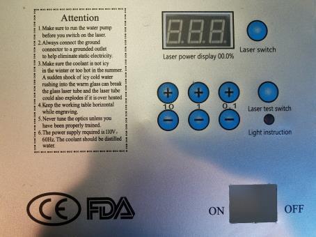
13 Testing the Digital Panel C Caution: This procedure must be done with the power on. Caution: This If you have this kind of procedure must be LPS connect the meter done with the power like this on. GD I If you have this kind of LPS connect meter like this GD At the control panel change the digital values with the 4 digit controls I As the digits are increased/decreased the voltage on the meter should change in the range of 0-5vdc If the correct voltage is not present or does not change try : Use this scale Check the wiring continuity between the panel and the I pin of the LPS. More Info: Replace the Digital Panel R
14 Testing the Internal Fuse This is the part you are testing. TUR OFF POWER Disconnect the AC connector Measure the resistance across the fuse. If it's not 0 ohms then the fuse is blown. Use this scale
15 Dangling endpoints G You got here because your LPS is not a type supported by this document More help can be found here: R You got here because you need more help. mmunities/ ?np=wawcHeygme zumb6fhbqhgengwuh izmdtjgcqf2amv2dzeje om/ S You got here because you have an internal problem with your LPS. You can buy a new one or try a repair. Rrepairing-k40-lps
16 Testing Methods ote: your DVM may not be the same as the one depicted in these drawings. Adapt this content to your particular DVM scale, connections and operation.
17 Using a DVM to Measure 0-5VDC Use this scale Connect to ground Connect to the pin expecting 0-5vdc
18 Using a DVM to Measure 0-24VDC O Use this scale Connect to ground Connect to the pin expecting 0-24vdc
19 Using a DVM to Measure 120 VAC P Use this scale Connect one side of the AC expecting 120vac Connect to the other side of AC expecting 120vac


20 Using a DVM to Measure 220 VAC Q Use this scale Connect one side of the AC expecting 240VAC Connect to the other side of AC expecting 240VAC
This document describes the procedure for doing a power trace on the SM5 and Gauntlet Stepmills.
 SM5/Gauntlet Stepmill Power Trace Applies to: SM5 (150005) + Gauntlet (150015) This document describes the procedure for doing a power trace on the SM5 and Gauntlet Stepmills. Latest Rev. Warning: the
High Voltage Power Supply (MMPS) - Troubleshooting Guide
 - Troubleshooting Guide") High Voltage Power Supply (MMPS) - Troubleshooting Guide LAST UPDATED: 09/19/2018 High Voltage Power Supply (MMPS) - Troubleshooting Guide Overview The High Voltage Power Supply (MMPS - MINIMILL Power
High Voltage Power Supply (MMPS) - Troubleshooting Guide LAST UPDATED: 09/19/2018 High Voltage Power Supply (MMPS) - Troubleshooting Guide Overview The High Voltage Power Supply (MMPS - MINIMILL Power
INDEX. Analog Board Boot and Voltage Test 2 Testing Input Channels 3 Testing Output Channels 4
 INDEX Analog Board Boot and Voltage Test 2 Testing Input Channels 3 Testing Output Channels 4 Digital Board Boot and Voltage Test 5 Testing Input Channels 6 Testing Output Channels 7 Display Testing 8
4. How to Connect the Fixture 3-Pin and 5-Pin XLR DMX Connectors:
 TABLE OF CONTENTS 1. Safety Instructions 2. Technical Specifications 3. Installation 4. How to Connect the Fixture 5. DMX512 Configuration 6. DMX512 Connections 7. How to Set the Unit 8. Troubleshooting
Instruction Manual. M Pump Motor Controller. For file reference, please record the following data:
 Instruction Manual M Pump Motor Controller For file reference, please record the following data: Model No: Serial No: Installation Date: Installation Location: When ordering replacement parts for your
AirTest Model CN9000 Series Sensor Controller
 AirTest Model CN9000 Series Sensor Controller AirTest Model CN9000 Series Sensor Controller THEORY OF OPERATION A basic CN9000 configuration consists of Input/Process/Display combination modules, a 3 relay
TABLE OF CONTENTS 1. Safety Instructions 2. Technical Specifications 3. Installation 4. How to Connect the Fixture 5. DMX512 Connections 6.
 TABLE OF CONTENTS 1. Safety Instructions 2. Technical Specifications 3. Installation 4. How to Connect the Fixture 5. DMX512 Connections 6. How to Set the Unit 7. DMX Configuration 8. IR Remote Control
Control. Part B, Section 2. This section covers the following unit configurations. 3400V 3500V Voltage 1, 2, 3 Pump Piston (D, E, F, G)
") Part B, Section 2 Model This section covers the following unit configurations. 3100V 3400V 3500V Voltage 1, 2, 3 Pump Piston (D, E, F, G) Manifold 4-Port (A) 6-Port (B or C) 2-Port (S or T) Vista Temperature
Part B, Section 2 Model This section covers the following unit configurations. 3100V 3400V 3500V Voltage 1, 2, 3 Pump Piston (D, E, F, G) Manifold 4-Port (A) 6-Port (B or C) 2-Port (S or T) Vista Temperature
MOBILE CONNECTOR - GEN 2 OWNER'S MANUAL
 MOBILE CONNECTOR - GEN 2 OWNER'S MANUAL UNITED STATES Contents Safety Information... 2 Save These Important Safety Instructions... 2 Warnings...2 Cautions...3 General Information... 4 Mobile Connector
OPERATING PROCEDURES for the UPS-S2 Universal Power Supply Series 2
 OPERATING PROCEDURES for the Universal Power Supply Series 2 Vanguard Instruments Co., Inc. 1520 S. Hellman Ave. Ontario, California 91761 TEL: 909-923-9390 November 2013 FAX: 909-923-9391 REV. 2 SAFETY
Installation Instructions
 Installation Instructions This document provides information on: important pre-installation considerations power supply requirements installing the module connecting the wiring using the indicators for
Pro-HD Model E. Troubleshooting Guide. ProHD chargers with a serial number that begins with an E are model E systems. Example:
 Pro-HD Model E Troubleshooting Guide ProHD chargers with a serial number that begins with an E are model E systems. Example: WARNING: During these troubleshooting tests the system can be plugged in and
ELECTRICAL SUPPLY TROUBLESHOOTING QUICK GUIDE SAFETY PRECAUTIONS
 ELECTRICAL SUPPLY TROUBLESHOOTING QUICK GUIDE 1. Circuit Breaker Tripping 2. Circuit Overload 3. Short Circuit 4. Ground Fault 5. Ground Fault Circuit Interrupter (GFCI) Tripping SAFETY PRECAUTIONS Basic
OPERATING INSTRUCTIONS 7 SERIES STATIC GENERATORS
 OPERATING INSTRUCTIONS 7 SERIES STATIC GENERATORS GB Contents Page 1 Introduction 4 2 Safety 5 3 Use 6 4 Checking on Delivered Equipment 6 5 General Specification and Dimensions 7 6 Positioning 10 7 Operating
ABM International, Inc. Lightning Stitch Checklist 9/13/2013
 ABM International, Inc. Lightning Stitch Checklist 9/13/2013 1) Piggy backed board assembly (1) Piggy back board assembly tested? Yes No 24v passed XB passed XA passed YB passed YA passed SAFE passed S/S
User's Guide. MiniTec TM Series Model MN25 MultiMeter
 User's Guide MiniTec TM Series Model MN25 MultiMeter Warranty EXTECH INSTRUMENTS CORPORATION warrants this instrument to be free of defects in parts and workmanship for one year from date of shipment (a
Treadmill Embedded Touch Screen Won t Power Up
 Treadmill Embedded Touch Screen Won t Power Up E-TRe and E-TRxe This document contains the necessary information to troubleshoot a treadmill with an embedded touch screen that will not power up. Follow
LVDT Test Device. Product Manual (Revision B) Original Instructions. Testing and Calibration of LVDT Feedback Devices on PG Governors
 Original Instructions. Testing and Calibration of LVDT Feedback Devices on PG Governors") Product Manual 55036 (Revision B) Original Instructions Testing and Calibration of LVDT Feedback Devices on PG Governors Operation Manual DEFINITIONS This is the safety alert symbol. It is used to alert
Product Manual 55036 (Revision B) Original Instructions Testing and Calibration of LVDT Feedback Devices on PG Governors Operation Manual DEFINITIONS This is the safety alert symbol. It is used to alert
Instruction Manual HPH-8
 Specifications HPH-8 Trigger cable 120-volt, Nema 1-15 Main Power 50-amps @ 240-volt AC Power receptacles (4) Nema 5-15 or 6-15 Maximum HID wattage 8000 watts (on 240-volt) 4800 watts (on 120-volt) Maximum
Model HU-224/225. Technical Information TI.224/ Humidity Transduce r FOR ADDITIONAL INFORMATION SEE HU-224/225 DATA SHEET
 Model /225 FOR ADDITIONAL INFORMATION SEE /225 DATA SHEET SPECIFICATIONS Accuracy*: ± 2% / ± 3% RH Range: 0-100% RH Hysteresis: ± 1% Supply Voltage:12-40 VDC 12-35 VAC (VDC output units only) Supply Current:
Vector Drive - Troubleshooting Guide
 Haas Technical Documentation Vector Drive - Troubleshooting Guide Scan code to get the latest version of this document Translation Available The Haas Vector drive is the source of power for the spindle
smar Specifications and information are subject to change without notice. Up-to-date address information is available on our website.
 smar www.smar.com Specifications and information are subject to change without notice. Up-to-date address information is available on our website. web: www.smar.com/contactus.asp PS302P - Fieldbus Power
MODEL 805 USER MANUAL
 MODEL 805 USER MANUAL All Rights Reserved Page 1 of 12 UNPACKING & INSPECTION Save all packing materials they are required for returns and warranty service. Inspect the 805 and packing materials for any
Operating Instructions
 Represented in Australia by: EMONA Instruments Pty Ltd 78 Parramatta Rd Camperdown NSW 2050 Tel: (02) 9519 3933 www.emona.com.au, www.protag.com.au testinst@emona.com.au Part Number 372A580 Revision 4
Instruction Manual. 2in1 LAN Tester & Multimeter. Model: 57314
 Instruction Manual 2in1 LAN Tester & Multimeter Model: 57314 1 Contents Introduction... Features... Safety Precautions.. Meter Description... Electrical Specification... Operation.. AutoRanging Multimeter.
Lightning Stitch Assembly
 ABM International, Inc. 1 1.0: Parts List Lightning stitch motor and drive assembly (Qty. 1) Lightning stitch piggy backed controller board assembly (Qty. 1) Touchscreen (Qty. 1) 2 9-pin Serial cable (Qty.
User Guide. Control Box. RoscoLED TM.
 RoscoLED TM Control Box User Guide This guide applies to the following RoscoLED Control Box models: RoscoLED Control Box 300W/Static White (293 22250 0000) RoscoLED Control Box 400W/VariWhite (293 22260
Electrical Management System (EMS) EMS-HW30C & EMS-HW50C
 EMS-HW30C & EMS-HW50C") Electrical Management System (EMS) EMS-HW30C & EMS-HW50C Installation & Operating Guide for: Model EMS-HW30C Rated at 120V/30A and Model EMS-HW50C Rated at 240V/50A Surgio Says Lifetime Warranty on all
Electrical Management System (EMS) EMS-HW30C & EMS-HW50C Installation & Operating Guide for: Model EMS-HW30C Rated at 120V/30A and Model EMS-HW50C Rated at 240V/50A Surgio Says Lifetime Warranty on all
2 in 1 LAN Tester and Multimeter Model:
 2 in 1 LAN Tester and Multimeter Model: 72-8495 1 IMPORTANT SAFETY INFORMATION Please read these instructions carefully before use and retain for future reference. This instrument is designed and manufactured
Air Hockey v7.0 Controller PCB Air Hockey 10v Transformer
 KNOWN ISSUES SORTED BY BOARD REVISION DYNAMO HOCKEY PCBs LISTED IN THIS WORKSHEET are no longer available for purchase or serviced by the manufacturer. Most tables can be upgraded to Dynamo s latest v7.0
PDC-X Digital Controller
 Operator s Manual LOR Manufacturing PDC-X Digital Controller Publication PDC_X_MAN_02252015_US Version 1.0.1-1-gfdf1ed4 Copyright 2015 Thoroughly read and understand all information presented in this
Installation Job Aid for Ethernet Routing Switch 5900 Series
 Installation Job Aid for Ethernet Routing Switch 5900 Series Notices NN47211-301 Issue 05.01 November 2017 Notice paragraphs alert you about issues that require your attention. The following paragraphs
Installation Instructions
 Installation Instructions Cat. No. 1771-OND Series B This document provides information on: important pre-installation considerations power supply requirements installing the module setting the fault mode
2200 Series. Quick Start Guide SAFETY CHECKLIST. Safety Made Simple
 Safety Made Simple SAFETY CHECKLIST KEEP unqualified/unauthorized personnel away from the test area ARRANGE test stations in a safe and orderly manner NEVER touch products or connections during a test
SERIES 7/9 TABLES & SERIES 8 BENCH. Troubleshooting Guide
 Troubleshooting Guide Cable Manager Low-Voltage Cable Stretcher Power Cable Controller Control Box Lifting Column Foot SERIES 7/9 TABLES & SERIES 8 BENCH HOW THEY WORK Each Lifting Column contains an individual
LASER PLUS OPERATING INSTRUCTIONS
 LASER PLUS OPERATING INSTRUCTIONS Phone: (209) 586-1022 (800) 545-1022 Fax: (209) 586-1026 E-Mail: salessupport@olsontech.com 025-370403 REV X9 www.olsontech.com 12/16/03 TABLE OF CONTENTS SYSTEM OVERVIEW
MAINTENANCE MANUAL. EDACS REDUNDANT POWER SUPPLY SYSTEM 350A1441P1 and P2 POWER MODULE CHASSIS 350A1441P3, P4, AND P5 POWER MODULES TABLE OF CONTENTS
 MAINTENANCE MANUAL EDACS REDUNDANT POWER SUPPLY SYSTEM 350A1441P1 and P2 POWER MODULE CHASSIS 350A1441P3, P4, AND P5 POWER MODULES TABLE OF CONTENTS SPECIFICATIONS*... 2 INTRODUCTION... 3 DESCRIPTION...
Model 2460-KIT. Screw Terminal Connector Kit. Description / September 2014 *P * 1
 Keithley Instruments 28775 Aurora Road Cleveland, Ohio 44139 1-800-935-5595 http://www.keithley.com Model 2460-KIT Screw Terminal Connector Kit Description The Model 2460-KIT Screw Terminal Connector Kit
RVDT Setup and Polarity Checking Tool for EG Governors. Product Manual (Revision B) Original Instructions T87444
 Original Instructions T87444") Product Manual 01504 (Revision B) Original Instructions RVDT Setup and Polarity Checking Tool for EG Governors T87444 Operation and Calibration Manual General Precautions Read this entire manual and all
Product Manual 01504 (Revision B) Original Instructions RVDT Setup and Polarity Checking Tool for EG Governors T87444 Operation and Calibration Manual General Precautions Read this entire manual and all
Installing the Cisco ATA
 CHAPTER 2 This section provides instructions for installing the Cisco ATA 186 and Cisco ATA 188. Before you perform the installation, be sure you have met the following prerequisites: Planned the network
SERIES 7 TABLES PRE-DECEMBER Troubleshooting Guide. IMPORTANT NOTE: This guide applies to models shipped prior to December 2015 only.
 Troubleshooting Guide Control Box (PRE-DECEMBER 2015) Low-Voltage Cable Cable Manager Controller Lifting Column Stretcher Foot Power Cable SERIES 7 TABLES PRE-DECEMBER 2015 HOW THEY WORK Each Lifting Column
Instruction Manual. Electrical Management System (EMS) EMS-HW30C & EMS-HW50C
 EMS-HW30C & EMS-HW50C") Instruction Manual Electrical Management System (EMS) EMS-HW30C & EMS-HW50C EMS-HW50C EMS-HW30C! CAUTION These instructions are intended to provide assistance with the installation of this product, and
Instruction Manual Electrical Management System (EMS) EMS-HW30C & EMS-HW50C EMS-HW50C EMS-HW30C! CAUTION These instructions are intended to provide assistance with the installation of this product, and
SPECIAL INSTRUCTIONS FOR CAPACITORS COMPACT GENERATORS
 SPECIAL INSTRUCTIONS FOR CAPACITORS COMPACT GENERATORS (WITH CAPACITOR CHARGER BOARD A3517-02) The process depends on Generator and System configuration. This document applies to installation of Capacitors
TD-700 FLUOROMETER SERVICE MANUAL
 TD-700 FLUOROMETER SERVICE MANUAL July 1996 CONTENTS Page Section 1 INTRODUCTION 2 Section 2 PRELIMINARY CHECKS 3 Section 3 TROUBLESHOOTING GUIDE 5 A. Lamp (Fluorescent) 5 B. Lamp Heater 7 C. Fan 8 D.
SCHOTT FLM 4 Fiber Lighting Modul. Operating Instructions
 SCHOTT FLM 4 Fiber Lighting Modul Operating Instructions Contents 1. Important information 3 2. Scope of Delivery 3 3. Intended use 3 4. Safety information 4 5. Operation 5 5.1. LED Optics Module 5 5.2.
Telephone Controller INSTRUCTION MANUAL MODEL CT TABLE OF CONTENTS SUMMARY INSTALLATION Connection to an Automatic Device...
 INSTRUCTION MANUAL Telephone Controller We thank you for trusting Aube technologies and hope that you will be entirely satisfied. For any questions concerning the CT241 telephone remote control, please
LINE VOLTAGE TESTER CT101 USER S MANUAL. Please read this manual carefully and thoroughly before using this product.
 LINE VOLTAGE TESTER USER S MANUAL CT101 Please read this manual carefully and thoroughly before using this product. KEY FEATURES Visual indication of AC or DC voltage Easy to use approved Safe for CAT
OPERATING INSTRUCTIONS AND SERVICE MANUAL BASKETBALL SHOTCLOCK MODEL MP-5299
 OPERATING INSTRUCTIONS AND SERVICE MANUAL BASKETBALL SHOTCLOCK MODEL MP-5299 EFFECTIVE S.N. 17,000, December, 2000 TABLE OF CONTENTS 1. General Information 1.1 Description 1.2 Identification 1.3 Damage
ETM Supplement: NSX Cellular Phone Troubleshooting
 September 26, 1995 YEAR MODEL VIN APPLICATION BULLETIN NO. ALL NSX ALL with 95-018 Cellular Phone ETM Supplement: NSX Cellular Phone Troubleshooting Test the phone as described under Components Check below.
Operating Instructions & Service Manual FOULS
 FOULS Operating Instructions & Service Manual FOULS Basketball Player Fouls Panels Model MP-5215 EFFECTIVE S.N. 17,100, June 18, 2001 TABLE OF CONTENTS PAGE 1. GENERAL INFORMATION 3 1.1 DESCRIPTION 1.2
A double yoke enables it to be operated in several positions. receiving device and then to others in a continuous "daisy chain" fashion.
 Page 1 of 5 FEATURES AND SPECIFICATIONS LEDS: 54 1 Watt LEDs ( 36 white, 18 amber) Beam angle: 25 º Control system: DMX-512 DMX channels: 4 DMX connectors: 3 pin XLR LED lifetime: 60,000 hours Voltage:
DSI-4. DMX Optically Isolated 1x4 Splitter. D Series. DSI_4 Users Manual r3.lwp copyright 2009, 2010, 2011 ELM V. T. Inc.
 DSI-4 DMX Optically Isolated 1x4 Splitter D Series 1 Table Of Contents IMPORTANT SAFEGUARDS... DSI-4 OVERVIEW... CONNECTION... PCB BLOCK DIAGRAM... SERVICING... TROUBLESHOOTING... SPECIFICATIONS... 2 3
Innovation First, Inc. Operator Interface Reference Guide
 11.8.2002 www.innovationfirst.com Page 2 Table of Contents 1. Operator Interface Basics...3 2. Input Power...4 3. RS-422 Radio...4 4. Operator Interface Ports 1, 2, 3, and 4...4 5. Tether Port...11 6.
R & D SPECIALTIES SERIES 100 RO CONTROLLER USERS MANUAL. 2004, by R & D Specialties, Inc. All Rights Reserved.
 R & D SPECIALTIES 2004, by R & D Specialties, Inc. All Rights Reserved. No part of this document may be copied or reproduced in any form or by any means without the prior written permission of R & D Specialties.
NSI DIGITAL DIMMING SYSTEM DDS 5300 / 5600 DIMMER PACK
 INTRODUCTION NSI DIGITAL DIMMING SYSTEM INSTALLATION AND OPERATION GUIDE The NSI DDS 5300 and DDS 5600 dimmers represent a key part of a state of the art, integrated lighting control system. These dimmers
LED PANEL. User Manual Please read the instructions carefully before use LED-7TC. Innovation, Quality, Performance 15-
 LED PANEL LED-7TC Innovation, Quality, Performance User Manual Please read the instructions carefully before use 15- 9. Fixture Cleaning TABLE OF CONTENTS 1. Safety Instructions 2. Technical Specifications
Installation Job Aid for Ethernet Routing Switch 3600 Series
 Installation Job Aid for Ethernet Routing Switch 3600 Series Notices NN47213-303 Issue 03.01 November 2017 Notice paragraphs alert you about issues that require your attention. Following are descriptions
Additions, Revisions, or Updates
 1 3 39-12 SUBJECT DATE SPN 625/FMI 2 and 9 (ACM2.1) April 2012 Additions, Revisions, or Updates Publication Number / Title Platform Section Title Change DDC-SVC-MAN-0084 MY13 DD Platform SPN 625/FMI 2
CHAPTER 3B: ELECTRONIC POWER STEERING
 Electronic Power Steering CHAPTER 3B: ELECTRONIC POWER STEERING NOTE: The basic steering system, such as the tie rod ends, drag links axles, etc., is covered in Chapter 3A: Steering. In 2012, Cub Cadet
ColourChaser Touch. Installation Guide
 ColourChaser Touch Installation Guide Dimensions C I S 110 29 72 Ø 4.5 56 85 I 2 3 4 100 77 ColourChaser Touch - Dimensions in mm Bracket - Dimensions in mm 2 Philips ColourChaser Touch Manual Content
Installation Job Aid for VSP 4850GTS
 Installation Job Aid for VSP 4850GTS Notices Release 6.1.0.0 NN46251-308 Issue 02.01 November 2017 Notice paragraphs alert you about issues that require your attention. The following paragraphs describe
RGBW Mini Moving Head Stage Spot Light Model: SSL1. User Manual.
 RGBW Mini Moving Head Stage Spot Light Model: SSL1 User Manual www.talentaudio.com Thank you for purchasing the Talent RGBW Mini Moving Head Lighting Fixture. Please read this user guide for safety and
EPS Power Supply
 EPS - 600 Power Supply Installation and Operation Manual Version 1.0 *This instrument is intended for laboratory use only Index A. Important Notice ----------------------------------------------------------------
PN PSTK-120 PowerSwitch Tail 120vac Kit PN PSTK-240 PowerSwitch Tail 240vac Kit
 CAUTION: Please make sure you have or have access to the skills necessary to assemble and use this product. Always secure the case with the included screws before applying electrical power to the power
User's Guide. Model W 3-in-1 Switching DC Power Supply
 User's Guide Model 382260 80W 3-in-1 Switching DC Power Supply Introduction Congratulations on your purchase of the Extech 80W 3-in-1 Switching DC Power Supply. The Model 382260 has three output ranges
Illuminator User Guide
 Illuminator User Guide Vega Slimline Illuminator Range Models covered by this manual: UFO VEGA M UFO VEGA DMX UFO VEGA 0-10V Please read this manual fully before installing, operating or performing maintenance
RF0250 RF1100 RF1200 RF1300 RF1600
 RF0250 RF1100 RF1200 RF1300 RF1600 Power Amplifier User Manual Issue 5 September 2017 LAPLACE INSTRUMENTS LTD Page 1 Page 2 Caution This unit produces high RF-power. It must be assured that maximum radiation
RobotEye RELW60. High Speed Long Wave Infra-Red Thermal Imaging System User Manual
 RobotEye RELW60 High Speed Long Wave Infra-Red Thermal Imaging System User Manual. Unit F1, 13-15 Forrester St Kingsgrove NSW 2208 Australia ii Copyright Notice and Disclaimer Copyright 2015 ( Ocular Robotics
TROUBLESHOOTING CHAPTER
 CHAPTER TROUBLESHOOTING CAUTION: Turn AC power off before attempting any of the following procedures, unless otherwise specified. Failure to do so may damage equipment, cause personal injury, or void warranty.
Vector Drive - Troubleshooting Guide
 Haas Technical Documentation Vector Drive - Troubleshooting Guide Scan code to get the latest version of this document Translation Available The Haas Vector drive is the source of power for the spindle
Installation and Operation Guide for PD5200 and PD5300 Automatic Transfer Switch
 Installation and Operation Guide for PD5200 and PD5300 Automatic Transfer Switch PD52 PD52S & PD52DCS PD53-100 te: The PD52S & PD52DCS are provided with LED lights. The GREEN LIGHTS indicate Shore Power
GILLIG ELECTRIC BUS Diagnostic Software User Guide & Troubleshooting Guide 8A Rev C Last Revised: 3/23/2017
 GILLIG ELECTRIC BUS Diagnostic Software User Guide & Troubleshooting Guide 8A003378 Rev C Last Revised: 3/23/2017 Table of Contents Section 1: Introduction... 2 Connector Definitions... 2 Location of Connectors...
Model 7705 Control Module
 www.keithley.com Model 7705 Control Module User s Guide PA-696 Rev. D / October 2006 A G R E A T E R M E A S U R E O F C O N F I D E N C E Safety Precautions The following safety precautions should be
Vector Drive - Troubleshooting Guide
 Haas Technical Documentation Vector Drive - Troubleshooting Guide Scan code to get the latest version of this document Translation Available The Haas Vector drive is the source of power for the spindle
Chameleon Labs Model CPS-501 Powered Chassis
 Chameleon Labs Model CPS-501 Powered Chassis Owner s Manual 704 228 th Avenue NE, # 826 Sammamish, WA 98074 206-264-7602 www.chameleonlabs.com Revision C May 2010 Your Model CPS 501 Powered Chassis has
2 in1 LAN Tester & Multimeter. Model: PCE-LT 1
 www.pce-industrial-needs.com Tursdale Technical Services Ltd Unit N12B Tursdale Business Park Co. Durham DH6 5PG United Kingdom Phone: +44 ( 0 ) 191 377 3398 Fax: +44 ( 0 ) 191 377 3357 info@tursdaletechnicalservices.co.uk
MultiJAMMA Switchboard Installation and User s Manual
 MultiJAMMA Switchboard Installation and User s Manual 2000, Clay Cowgill Revision 1.0 Notice Regarding this Kit Warning! Although this kit has been tested and the techniques used will not directly cause
VS. 4 Game Selector INSTALL GUIDE
 VS. 4 Game Selector INSTALL GUIDE Each DK Selector includes the following items: 1. VS. 4 Game Selector PWB 2. 4 power cables 12, 14, 16 & 18 3. Ribbon daisy chain cable 4. Mounting feet and screws Some
OPERATING INSTRUCTIONS AND SERVICE MANUAL HOCKEY SCOREBOARD. MODEL MP-3579 WITH MP-3000 Control
 OPERATING INSTRUCTIONS AND SERVICE MANUAL HOCKEY SCOREBOARD MODEL MP-3579 WITH MP-3000 Control EFFECTIVE S.N. 11370 MARCH 7,1996 TABLE OF CONTENTS 1. General Information 1.1 Description 1.2 Identification
Crossfire. User Manual. Order code: EQLED061
 Crossfire User Manual Order code: EQLED061 Safety advice WARNING FOR YOUR OWN SAFETY, PLEASE READ THIS USER MANUAL CAREFULLY BEFORE YOUR INITIAL START-UP! Before your initial start-up, please make sure
********SERVICE MANUAL******** MODELS:
 ********SERVICE MANUAL******** MODELS: 75211-10 Variable Speed Drive, 5000 RPM, 115 V 75211-15 Variable Speed Drive, 5000 RPM, 230 V, CE Mark 75211-60 Variable Speed Drive w/pump, 9000 RPM, 115 V 75211-62
TRC-190 User s Manual
 First Edition, November 2008 www.moxa.com/product 2008 Moxa Inc. All rights reserved. Reproduction without permission is prohibited. The software described in this manual is furnished under a license agreement
Autoranging Multimeter plus IR Thermometer Extech 450 Patented
 User's Guide Autoranging Multimeter plus IR Thermometer Extech 450 Patented Introduction Congratulations on your purchase of the Extech 450 (part number EX450) Autoranging Multimeter plus IR Thermometer.
Power Hub Cat. No. 83A00-1. Installation Manual WEB VERSION
 Power Hub Cat. No. 83A00-1 Installation Manual WARNINGS AND CAUTIONS Read and understand all instructions. Follow all warnings and instructions marked on the product. Do not use this product near water
Light Source User Guide
 Light Source User Guide Mercury Slimline Light Source Range Models covered by this manual: UFO MERSL3000M UFO MERSL 3000DMX UFO MERSL 3000 0-10V Please read this manual fully before installing, operating
STATUS Shiloh Road Alpharetta, Georgia (770) FAX (770) Toll Free
 FAX (770) Toll Free") Instruction Manual Model 1582-45L Data Switch September 2010, Rev A REMOTE LOCAL SWITCH STATUS SELECT REMOTE LOCAL LOCAL SELECT CHANNEL SELECT POWER MODEL 1582 SWITCH CROSS TECHNOLOGIES, INC. Data, drawings,
Instruction Manual Model 1582-45L Data Switch September 2010, Rev A REMOTE LOCAL SWITCH STATUS SELECT REMOTE LOCAL LOCAL SELECT CHANNEL SELECT POWER MODEL 1582 SWITCH CROSS TECHNOLOGIES, INC. Data, drawings,
Zero Volt Monitor Installation, Operation and Maintenance
 TECHNICAL BULLETIN TB-6515 Zero Volt Monitor Installation, Operation and Maintenance Made in the United States of America strap properly, the monitor measures the loop resistance consisting of one wire
DK 4 Game Selector INSTALL GUIDE
 DK 4 Game Selector INSTALL GUIDE Each DK Selector includes the following items: 1. DK Selector PWB 2. 4 power cables 12, 14, 16 & 18 3. Ribbon daisy chain cable 4. Mounting feet and screws Some of the
A120 A W/240W PA Mixer-Amplifier 70V/100V
 A120 A240 120W/240W PA Mixer-Amplifier 70V/100V User Manual TABLE OF CONTENTS 1. SAFETY PRECAUTIONS...3 2. GENERAL DESCRIPTION......5 3. FEATURES AND FUNCTIONS 3. 1 Front Panel...6 3.2 Rear Panel... 6 4.
This 4200-RM Rack Mount Kit is for installation in 4200-CAB series cabinets only.
 Keithley Instruments, Inc. 28775 Aurora Road Cleveland, Ohio 44139 (440) 248-0400 Fax: (440) 248-6168 www.keithley.com Model 4200-RM Rack Mount Kit Packing List Introduction NOTE This 4200-RM Rack Mount
INSTALLATION AND MAINTENANCE INSTRUCTIONS For Chemline A- & Q-Series Actuator with Digital (AC) Positioner
 Positioner") INSTALLATION AND MAINTENANCE INSTRUCTIONS For Chemline A- & Q-Series Actuator with Digital (AC) Positioner General: The Digital High-performance position AC Controller is designed to control quarter-turn
INSTALLATION AND MAINTENANCE INSTRUCTIONS For Chemline A- & Q-Series Actuator with Digital (AC) Positioner General: The Digital High-performance position AC Controller is designed to control quarter-turn
IRB-RET O P E R A T I N G I N S T R U C T I O N S UNIVERSAL SAFETY RETROREFLECTIVE PHOTOEYE U L MONITORED DEVICE
 O P E R A T I N G I N S T R U C T I O N S IRB-RET UNIVERSAL SAFETY RETROREFLECTIVE PHOTOEYE U L 3 2 5-2 0 1 6 MONITORED DEVICE 4564 Johnston Parkway, Cleveland, Ohio 44128 P. 800 426 9912 F. 216 518 9884
RTK3 Logic Controller User Manual Revised
 RTK3 Logic Controller User Manual Revised 6-24-08 1 of 16 svn://software/hardware/rtk3/docs/rtk3_man.doc MRR 6/24/08 9:03 AM Overview The RTK3 is intended to simplify and expedite control wiring. Centroid
Model: VA/230W UPS Backup System
 IMPORTANT SAFETY INSTRUCTIONS (SAVE THESE INSTRUCTIONS) This manual contains important safety instructions. Please read and follow all instructions carefully during installation and operation of unit.
RS3000 SERIES BILL ACCEPTORS
 Flash Diagnostic Codes RS3000 SERIES BILL ACCEPTORS INSTALLATION GUIDE s of the bill acceptor. Below is a chart that lists all the flash codes of the RS3000 Bill Acceptor and a description of each code.
BERMAD Irrigation. BIC Wire RTU
 BIC 2500 2-Wire RTU System guide Versions : 2007 Contents 1. System Overview 3 1.1. Technical SpecificationS 3 1.1. System ComponentS 4 2. Installation 5 2.1 Cable Test 5 2.2. Ground RodS 6 2.3 Addressing
Blitzer Strobe. User Manual. Order code: EQLED366
 Blitzer Strobe User Manual Order code: EQLED366 Safety advice WARNING FOR YOUR OWN SAFETY, PLEASE READ THIS USER MANUAL CAREFULLY BEFORE YOUR INITIAL START-UP! Before your initial start-up, please make
OPERATING MANUAL. Model Number:W625. Name:Hit Music VERSION: ENG.S.DMH01.5
 Model Number:W625 Name:Hit Music VERSION: ENG.S.DMH01.5 OPERATING MANUAL The actual product you have received may differ slightly from the illustration. The specifications of the machine and the contents
Network Controller. Installation/Troubleshooting Instructions NK220 COM1131C
 Network Controller NK220 COM1131C Installation/Troubleshooting Instructions Part No. 70399101R4 October 2009 Table of Contents Getting Started... 2 Components of Network Controller... 2 System Overview...
Power LED Beam 56 Narrow
 Power LED Beam 56 Narrow owners manual 2 Thanks for choosing the GLX LIGHTING PLB-56N. The PLB-56N is a full RGB color mix par can DMX- 512 controllable, made up of highly efficient and bright LED s measuring