GENERAL CATALOGUE. Equipments. Devices. fanox.com
|
|
|
- Monica Erika Harper
- 5 years ago
- Views:
Transcription
1 GENERAL CATALOGUE SELF-POWERED s Equipments Devices fanox.com


2 years of protection Fanox designs and manufactures electronic protection relays for Low and Medium Voltage. Since it was founded in 1992, the main focus has been to help our customers to improve power systems reliability and safety at a reduced cost. With an in-house R+D+I department always searching for the most suitable technical solution, and thanks to our innovative spirit and successfully proven experience with thousand of field installed devices operating in top conditions for years, our SELF POWERED Protection Relays have become a reference in the electrical sector. I+D+i Quality is a commitment to all of us in Fanox. We have been certified by DQS as an ISO 9001:2008 company. SELF POWERED From our headquarters at Bizkaia Technology Park in the north of Spain, we serve customers and utilities worldwide. Fanox protects your daily life more than you can imagine....taking care of systems operability and people safety.
3 FANOX PRODUCTS G SYNCHRONISM CHECK CHECK GENERATOR PROTECTION VOLTAGE & FREQUENCY PROTECTION POWER TRANSFORMATOR TRANSFORMER TRANSFORMATION SUBSTATION POWER TRANSFORMATOR TRANSFORMER FEEDER PROTECTION SIL-B LINE PROTECTION SIL-A SIL-G RMU s PROTECTION / / MRMU s PROTECTION SIA-A SIA-B SIA-C SIA-B SIA-D SELF POWERED SIA-E SIA-C SIC-A SF6 & METALCLAD SWITCHGEAR PROTECTION SIL-V DIRECTIONAL PROTECTION SIA-F SIL-D TRANSMISSION LINE Communication Solutions REDBOX PROTOCOL GATEWAY REDUNDANT PROTOCOL GATEWAY SIA-F DISTRIBUTION LINE SIA-D PRIMARY DISTRIBUTION SECONDARY DISTRIBUTION POWER T & D PROTECTION AND SELF POWER CURRENT TRANSFORMERS FOR MEDIUM VOLTAGE SURGE PROTECTION EARTH LEAKAGE PROTECTION SURGE PROTECTION M MANUAL MOTOR STARTERS MANUAL MOTOR STARTERS MMOTOR/PUMP PROTECTION CONTROL RELAYS EARTH MEASURING LEAKAGE RELAYS PROTECTION AMP CHART RECORDER CONTROL RELAYS AMP CHART RECORDER CURRENT TRANSFORMERS CURRENT TRANSFORMERS TIMERS TIMERS LOW VOLTAGE PROTECTION PROTECTION & CONTROL & CONTROL MOTOR/PUMP PROTECTION SOFT STARTERS SOFT STARTERS THERMISTOR SENSORS THERMISTOR SENSORS M M 3
4 POWER T&D Index What is SELF-POWER?... 6 Why is Fanox the world s leading manufacturer of SELF-POWERED Relays?... 9 Evolution of RMU s Protection Relays Protection functions, common features and Standards SIA Relay Selection guide SIL Relay Selection guide Relay Application guide Introduction to SIA Relays SIA-B (Dual & Self powered) OC&EF Protection for Secondary Distribution with specific transformers Main characteristics Technical specifications Selection & Ordering data Application and installation options for our SIA-B Relay SIA-C (Dual & Self powered) OC&EF Protection for Secondary Distribution with standard transformers Main characteristics Technical specifications Selection & Ordering data Some success applications for our SIA-C Relay SIA-F OC&EF Protection for Secondary Distribution with auxiliary supply Main characteristics Technical specifications Selection & Ordering data Introduction to SIL Relays SIL-D OC&EF / Directional Protection for Primary & Secondary Distribution Main characteristics Technical specifications Selection & Ordering data
5 SIA & SIL Software 5 Five year guarantee SIL-A OC&EF Protection for Primary Distribution Main characteristics Technical specifications Selection & Ordering data SIL-B Feeder Protection Main characteristics Technical specifications Selection & Ordering data SIL-G Generator Protection Main characteristics Technical specifications Selection & Ordering data SIL-V Voltage & Frequency Protection / Synchronism Relay Main characteristics Technical specifications Selection & Ordering data Accessories CT-MTP for protection and power supply CT-MTP1000/1A TCM Trip coil module PRT Strikers KITCOM Battery power supply SIC M SICOM Communication software Introduction to SIC-A Communication Solutions Redundancy Protocols Gateway (PRP/HSR) Main characteristics Main functions Technical specifications Selection & Ordering data

6 What is self - power? The concept Self-Power defines the supplying mode of electronic protection relays for Medium Voltage. It means that there is no need for auxiliary voltage to power the relay and that the energy is obtained directly from the line that we are protecting. How do we obtain power from the line? The energy is obtained through current transformers installed in the line we want to protect. There are two options respecting to the transformers: Standard transformers /1 or /5 Specific transformers: in this case the secondary current is not standard and they provide some special feature respect the standard Cts like a higher saturation level, or a wider measurement range. RMUs based on switches with 3 fuses are being substituted by SF6 Circuit breakers and self powered relays. Advantages of self-powered relays vs. fuses Low current faults: Fuses only can break high current faults. Circuit breaker with self powered relays can detect and clear low current faults avoiding the destruction of the MV/LV transformers. Protection Selectivity: The discrimination with fuse curves becomes difficult. It is possible to choose the right curve in self powered relays to ensure coordination between MV and LV protection. Inrush current: Transformer energizing produces high transient inrush current. This is a natural phenomena and the protection should not operate. Fuses are not able to distinguish this current and the trip cannot be blocked. Circuit breaker with self powered relay allows greater flexibility to avoid the trip. Temperature: Fuses are weak into harsh environment and the different temperatures can provoke 2 situation: High temperature: Undesired trips. Low temperature: The trip does not happen instead the fault current is high enough. Saving Costs: Circuit-breaker with self power reduces costs for 2 reasons: Self powered relays are maintenance free. There is no need to keep large stocks of fuses. 6
7 Which opening mechanism will be used with self powered relays? Self powered relays do power themselves from the primary current and the energy is scarce, so an efficient management of this energy is indispensable. Due to this situation using coils is not viable because they have a very high electrical consumption. The solution is to use a striker. But what is a striker? It s a bistable device with a simple action. It consists on an electromagnet that is charged when the breaker is closed (To trip, it required low energy, 100 millijoules approximately) The striker shaft is moved by a spring. And activated by a polarized low power electrical signal, supplied by the relay if a fault occurs. Could a Self-powered Relay be used if the opening mechanism is a coil instead of a striker? Yes, it is possible to use a Self-powered Relays if the installed opening mechanism is a coil, but it is necessary to install an external device with the relay. Fanox offers amongst its products catalogue the TCM adapter. This device is connected to the trip contact of the relay and provides the required energy to trip a coil. How does TCM work? TCM is an energy accumulator that can be charged, through its auxiliary supply terminals, before the installation or once the device is installed, if in the installation auxiliary supply is available. The charging time is 10 seconds approximately and once the power supply is lost the TCM has three days of autonomy. 7

8


, to manage the incidents")

9 Specialized in Ring Main Unit and Switchgear Protection Why is Fanox the world s leading manufacturer of SELF POWERED Relays? Our innovative spirit, the direct care of the market requirements and our extensive experience in the manufacture of protection relays, have made our Self Powered Relays a reference worldwide. The relays include the latest technology: LCD, keyboard, event recording, SCADA communication, PC software... Utilities worldwide have relied on our technology for over 25 years. Main advantages over other brands: The relays are self powered by the current measured by the CTs fitted on the lines. The MAIN ADVANTAGE comparing with other self-powered relays in the market is that Fanox relays do not required internal batteries. This means that the maintenance of transformation centers is heavily reduced. High electromagnetic compatibility makes FANOX relays the safest in the market. KEMA certification proves it. 5 years warranty al least. Standard CTs /1A or /5A can be used saving money due to specific CTs are not required. Fanox self-powered relays are able to trip all the strikers in the market. Thanks to a setting that allows the user to select the required voltage by the striker. Possibility of LOCAL AND REMOTE communication. Very intuitive menu, extremely easy to set. Our flexible design offers solutions for all the applications worldwide: coils, strikers, dual-powered installations... No one in the market gives more quality and specifications with so competitive prices. Besides, all models can be powered from an external battery, in order to facilitate the commissioning of the centers (the settings and configuration procedure can be carried out without installing the relay), to manage the incidents that may occur and also to manage the devices in adverse conditions. Solutions for the Smart Grid and Predictive Maintenance Network Our relays incorporate new industry trends in remote communication protocols for automatized substations. In all Fanox relays for Primary distribution (SIL) the protocol IEC can be included. This protocol is an international standard designed for the integration and communication of the electrical devices in the substations. Besides, it uses new concepts and the most advanced technical solutions to cover the data management and to simplify the applications and devices integration 9
. Its applications are quite varied. But first of all What is a RMU?")

10 Evolution of RMU s Protection Systems SIA-C Self and Dual Powered protection relay is the most effective protection relay for SF6 RMUs for secondary distribution (up to 13.8kV, 17.5kV, 24kV or 34.5kV). Its applications are quite varied. But first of all What is a RMU? We can define a Ring Main Unit as a standard piece of switchgear in distribution systems comprising of switches for switching power cable rings and of switches in series with fuses or circuit breakers for the protection of distribution transformers Breaking components: 1 Vacuum Circuit Breaker 2 Earth switch 3 Ring Switch with remote control 4 Ring Switch with remote control 5 Self Powered relay protection 10


11 Changes and developments RMUs protection systems have experienced in recent years an outstanding development and modernization. Protection, control measurement, communication in addition to the need of simplify the maintenance of the installations are behind the current trend of change. Switchgears and RMUs need to be firmly and safely under control and traditional RMUs based on switches with fuses don t meet the requirements of the market. The need for electronic devices without maintenance has passed from a desire to a necessity. RMUs based on switches with 3 fuses are being substituted by SF6 circuit breakers and self powered protection relays. This way, batteries are removed, events and alarms of the RMU are stored in the relay and the Grid can be remotely motorized thanks to the communications that FANOX s protection relays have. In most cases there is a lack of access to the installation. Not all facilities are roadside. Some are buried, or in areas of difficult access where replacing a fuse can entail a big problem. Circuit breaker can be opened by the action of tripping coils or tripping strikers. When self powered relays are installed in the SF6 RMUs, the circuit breaker is opened by the action of a tripping striker that is activated by up to a 24V supply that the self powered relay provides. The striker is an electromagnet that is loaded at the closing of the switchgear, and is required lowenergy trigger to release them. Different models and tensions, and in general the selection of it is a compromise between mechanical security and tripping energy, but in general are a reliable and high quality element. RMUs for primary distribution have a capacity of up to 50kA short circuits, rated currents up to 4000A. They usually use vacuum circuit breakers and air isolation. RMUs for secondary distribution have a capacity of up to 21kA short circuit, rated currents up to 630A. They usually use vacuum circuit breakers and SF6 isolation. All these improvements are focused in having the installation under the safest control and in saving cost in terms of material and personnel. Fanox as a specialist in SELF POWERED relays, is the best ally to adapt your switchgear to what market demands. 11
12 Protection functions & Standards Function 50 Instantaneous phase overcurrent Function 50N and 50N/G 50N = Instantaneous neutral overcurrent internally calculated (I A +I B +I C ) 50N/G = Instantaneous neutral overcurrent measured Function 50/51 Inverse time phase overcurrent Function 50/51N and 50/51 N/G 50/51N = Inverse time neutral overcurrent internally calculated (I A +I B +I C ) 50/51 N/G = Inverse time neutral overcurrent measured Curves IEC and ANSI Standard curves are used for the protection functions - 50/51, 50/51N, 46, 67 y 67N: - Normally inverse - Very inverse - Extremely inverse - Definite time Function 49 Thermal overload protection. Function 49T (External Trip) There is a direct trip input, normally associated with a bimetallic contact that is fitted to the power transformer, which serves as a backup for the current functions. In order for it to be a real backup, this input is not related to the protection processors. This means that the processors do not read the input and trip the striker, but the input acts directly on the striker, remaining operational for as long as the equipment is powered. This input is especially protected against electromagnetic noise. Function 81U Underfrequency protection Function 81O Overfrequency protection Function 25 Synchronism check Function 46 Inverse time negative sequence overcurrent Function 59 Defined time phase overvoltage Function 59N Defined time neutral overvoltage Function 27 Defined time phase undervoltage Function 37 Phase undercurrent Function 32/40 Defined time directional overpower Function 79, auto-recloser This function is the responsible of reclosing the breaker when a fault occurs. Function 67 It uses the voltage between phases as the polarization magnitude and the phase current as the operating variable. If the directional function 67 is not enabled, it behaves as a 51/50 function. The operative time starts when the following conditions are met simultaneously: - Polarization voltage higher than setting - Phase current higher than setting - Gap between phase current and polarization voltage is such that the phase current is within the area of the intervention. Function 67N, Neutral directional protection It uses the residual voltage as the polarization magnitude and the residual current as the operating variable. If the directional function 67N is not enabled, it behaves as a 50/51 N/G Function. The operative time starts when the following conditions are met simultaneously: residual voltage higher than setting residual current higher than setting the gap between the residual current and residual voltage is such that the residual current is within the area of the intervention. Trip Block for Switch disconnector protection Many transformation centers have a disconnector as a break element. As line breakers have a limited opening current, with short-circuit events at high currents the responsibility for opening falls on the fuses, because otherwise, opening the line breaker would mean destroying it. In order to deal with these situations, tripping either in phase or neutral is blocked when the measured current exceeds a preset value. Function 68, Logical Trip bus Function 68 allows the creation of a coordinated net of equipments installed in different levels of the line which enables the blocking or the tripping and whose objective is clearing the fault in the least damaging place of the application. Function 86 Function 86 allows to latch (lock out) the contact trip due to programmable logic (PLC). Function 52 This function allows monitoring of circuit breaker state and makes a preventive maintenance. Function 50BF This function allows showing a possible error of the circuit breaker opening. Function 74TCS, Trip Circuit Supervision This function allows the supervision of breaker s trip circuit. Function CLP, Cold Load Pick-up This unit is used in order to avoid non-desirable operations of overcurrent functions when the line is not energized. Function 74CT Current transformer supervision Function 46BC Open phase detection 12

13 MEASUREMENTS Phase and neutral are measured with an accuracy of ±2% over a band of ±20% of nominal and ±4% over the rest of the measurement range. The measurement range is from 0.02 until 30 times nominal current. TIME SYNCHRONIZATION IRIG-B: GPS Time Synchronization Protocol Communications protocol synchronization. SETTINGS GROUPS The relay has up to 4 settings groups for the protections settings. HMI The HMI consists of: A 20x2 LCD screen with alphanumeric characters that allow the equipment parameters to be set (adjusted) and monitored (measurements, statuses, events). A membrane keyboard with six keys that allow you to navigate the menus and access information of interest. A seventh button RESET, allows you to reset the bistable and led indicators and the events log. For security reasons, an access code is needed to modify the settings. LED indicators showing the type of power supply being used at all times. The relay can use more than one power source at one time. Bistable magnetic indicators that signal the cause of tripping. These indicators remain in position when the equipment loses power, reducing the time the maintenance service needs to identify the cause of tripping. COMMUNICATIONS The relays have a communication local port on the front of the equipment and rear ports on the back for remote communication. The SICom software with Windows W7, W8, W8.1 and W10 uses a graphic user interface to allow you to access all equipment information, modify the settings and save events. The software can be used locally by using the front port or remotely by using the rear RS485 port when the protocol is ModBus RTU. TEST MENU This allows you to use the HMI to verify correct operation of the LEDs, the bistable magnetic indicators, the trip contact and the outputs. Activating the trip contact from the test menu allows you to verify correct operation of the opening mechanism simply. SELF-DIAGNOSIS Diagnostic algorithms to generate the corresponding events are executed on starting up the equipment and all the time the relay is operating. EVENTS RECORD Events are recorded and ordered chronologically (up to 1024), allowing you to analyse what has happened with the installation over time (start-ups, tripping power supplies, etc.). They are recorded chronologically to the nearest millisecond in real time, thanks to the Real Time Clock (RTC). Events can be recorded on a non-volatile FRAM memory. FAULT REPORT A fault report is a record of specific events in the period of time when a fault occurs. Having a specific events record for the fault period is a significant help to resolve an incident. OSCILLOGRAPHY RECORDS The relay stores up to 5 oscillographic logs and 20 fault reports, with a resolution of 16 samples/cycle. The oscillography can be downloaded by communications through the Modbus protocol. The SICom communications program allows the oscillography to be downloaded and saved in COMTRADE format (IEEE C ). COM PORTS The relay has up to 3 communication ports in different format: USB, RS232, RS485, FOP, FOC, RJ45 (Ethernet). COM PROTOCOLS The relay supports the different protocols: ModBus RTU, Modbus TCP/IP, IEC , IEC , DNP3.0 (TCP/IP), DNP3 Serial, IEC
14 Protection functions & Standards EMC requirements - Emission Test Name Relay Test LEVELS Radiated emission IEC EN EN Conducted emission IEC EN EN EMC requirements - Immunity Radiated emission limit for Class A (group 1 for EN 55011) on Enclosure port. Frequency range 30MHz - 230MHz (Quasi Peak 40dBμV/m). Frequency range 230MHz MHz (Quasi Peak 47dBμV/m) Conducted emission limit for Class A (group 1 for EN 55011) on Auxiliary power supply port. Frequency range 0.15MHz 0.5MHz (Quasi Peak 79μV, Avg 66μV). Frequency range 0.5MHz 30MHz (Quasi Peak 73μV, Avg 60μV) Test Name Relay Test LEVELS 1MHz damped oscillatory waves Class 3, Repetition frequency 400Hz, Duration of each application 3s. IEC IEC Common mode for all terminals ±2.5kV. Differential mode for all terminals excepts Communication port ±1kV Electrostatic discharge IEC IEC Level 4, Contact discharge ±8kV. Air discharge ±15kV Radiated radiofrequency electromagnetic fields IEC IEC Electrical fast transients IEC IEC Surge IEC IEC Conducted disturbance induced by radio frequency fields Voltage dips, short interruptions and voltage variations IEC IEC IEC IEC IEC Ripple on DC input power port IEC IEC Power frequency magnetic field IEC IEC KHz damped oscillatory waves IEC Level 3, Test field strenght 10V/m, Frequency 80MHZ MHz and 1400MHz MHz, AM Modulation 80% for 1KHz carrier sinusoidal signal Level 4, Power supply to Earth terminals ±4kV, Signal and control terminals ±2kV. Repetition frequency 5KHz, Burst duration 75s. Level 4, Line to earth for all terminals ±4kV. Line to Line for all terminals excepts Communication port ±2kV Level 3, Applied voltage 10V, Frequency 0.15MHz - 80 MHz, AM Modulation 80% for 1KHz carrier sinusoidal signal, Dwell time 1s., Test duration >10s. DC Voltage Dips: 40%, 130ms and 70%, 100ms, 3 times every 10s. DC Voltage Interruption: 100ms, 3 times every 10s. Level 4, Ripple 15%, 50Hz and 100Hz Level 5, Continuous field strenght 100 A/m. Short field strenght for a duration of 3s A/m. Frequency 50Hz. Class 3, Repetition frequency 40Hz, Duration of each application 3s. Common mode: ±2.5kV. Differential mode: ±1kV Pulse magnetic fields IEC Field strenght 1000 A/m, Cadence between pulses 40s. Damped oscillatory magnetic fields Level 5, Field strenght 100 A/m, Frequency 100KHz and 1MHz, Repetition IEC frequency 40 trans./s at 100KHz, 400 trans/s at 1MHz, Duration of each application 3s. Ring wave immunity test IEC Level 4, Line to earth for all terminals ±4kV. Line to Line for all terminals excepts Communication port ±2kV Product safety requirements (including thermal short time rating) Test Name Relay Test LEVELS Impulse voltage IEC IEC AC or DC dielectric voltage IEC IEC Insulation resistance IEC IEC Protective bonding resistance IEC Burden Each group to earth and with rest of the groups in short-circuit ±5kV. Differential mode for each one of the groups ±1kV Each group to earth and with rest of the groups in short-circuit 2kVac, 50Hz, 1 minute 500V applied between each group to earth and with rest of the groups in short-circuit Test current 2xIn, Test voltage 12Vac during 60s. Resistance shall be less than 0.1 ohm Test Name Relay Test LEVELS AC burden for CT Declared on manual AC burden for VT IEC AC, DC burden for power supply AC, DC burden for binary inputs 14
15 Contact performance Test Name Relay Test LEVELS Contact performance IEC Communication requirements Test Name Relay Test LEVELS Communication requirements ModBus RTU IEC IEC IEC DNP 3.0 Climatic environmental requirements Test Name Relay Test LEVELS Cold Dry heat Change of temperature Damp heat IEC IEC IEC IEC IEC Cold Operation Ab, -25ºC, 72h Cold transport & Storage Ad, -40ºC, 72h Dry Heat Operation Bb, +70ºC, 72h Dry Heat transport & Storage Bd, +85ºC, 72h Change of Temperature Nb, Upper temp +70ºC, Lower temp -25ºC, 5 cycles, Exposure time 3h, Transfer time 2 min. Damp Heat Cyclic Db, Upper temp +40ºC, Humidity 93%, 2 cycles. Relay energized Damp Heat Steady State Test Cab, Upper temp +40ºC, Humidity 85%, 2 days. Relay not energized Mechanical requirements Test Name Relay Test LEVELS Vibration IEC IEC Shock IEC IEC Bump IEC IEC Seismic IEC IEC Vibration response, Class 1, 10Hz to 59Hz, 0,035mm and 59Hz to 150Hz, 0.5g n Vibration endurance, Class 1, 10Hz to 150Hz, 1g n Shock Response, Class 1, 5g n, Shock Withstands, Class 1, 15g n Bump, Class 1, 10g n Single Axis Sine Sweep, Class 1, X Axis: 1 to 9Hz, 3.5mm and 9 to 35Hz, 1g n ; Y Axis: 1 to 9Hz, 1.5mm and 9 to 35Hz, 0.5g n Electrical environmental requirements Test Name Relay Test LEVELS CT Input continuous overload IEC xIn without damage for continuous operation CT Input short time overload IEC xIn without damage for 1s short time overloading VT Input continuous overload IEC Declared on manual, without damage for continuous operation VT Input short time overload IEC Declared on manual, without damage for 10s short time overloading Enclosure protection Test Name Relay Test LEVELS Enclosure protection IEC IEC IP-54 Quality Management System Test Name Relay Test LEVELS Quality Management System ISO 9001:
16 Product selection guide OC & EF FOR SECONDARY DISTRIBUTION SIA SELF & DUAL POWERED (SELF+AUX) AUXILIARY POWERED SIA-B SIA-C SIA-F Auxiliary Supply 24Vdc 110Vac 230Vac 24Vdc 230Vac 48 Vdc Vac/Vdc Vdc / Vac Self Power Supply 3.2A, 6.4A, 12.8A, 25.6A or 51.2A depending on the CT. (x3) 0,1 In (x3) External battery USB cable/ Power bank KITCOM USB cable/ Power bank Internal battery (*) (*) Consumption 0,5 W 0,5 W 1,5 2,2 W CT Specific CT Standard 2,5VA Standard 0,5VA N/G N 1 50/ /51N/G /51N BF T CLP 1 Trip Block (Trip Bus) Programmable Logic V3 V3 V3 Counters Commands Sett. Group Inputs 1 1+EXT. TRIP 2 Outputs - / 2NC - NO 2 NC - NO / 3 NO 1 NO +1 NC - NO Output for STRIKER 1X (24 Vdc 135 mj) 1X (24 Vdc 135 mj) NO LEDs 2 LEDs +1MAG.FLAG 3 LEDs +3 MAG.FLAGS 3 LEDs configurable HMI 20X2 LCD + 7 keys 20X2 LCD + 7 keys 20X2 LCD + 7 keys Event Fault Report Oscillography 1 record x 22 cycles Current demand Local Port (frontal) USB RS232 USB Remote Port (rear) RS485 RS485 RS485 Communications Protocols ModBus RTU ModBus RTU ModBus RTU / DNP3.0 (Serial) Size of Vertical: x mm Horizontal: 185,80 x 102,7 mm Vertical Compacto: 177 x 155 mm Vertical Estándar: 177 x 189 mm Horizontal: 177,8 x 290,3 mm 167,80 x 120,65 mm (*) The internal battery is only an accessory. The relay operates independently of the battery. Its function is to allow the user to set the relay and analyze the information stored in fault reports and in the event menu when the relay is not powered, for example during the commissioning. 16
17 Product selection guide SIL OC & EF FOR PRIMARY DISTRIBUTION FEEDER PROTECTION GENERATOR PROTECTION SIL-D SIL-A SIL-B SIL-G SIL-V Auxiliary Supply Vdc/ Vac Vdc/ Vac 24 48Vdc Vdc/ Vac 24 48Vdc Vdc/ Vac Vdc/ Vac Consumption 3,3 4,5 W 3,3 4,5 W 3,3 5,5 W 3,3 5,5 W 3,3 5,5 W Current measurement Standard CT 0,5VA Standard CT 0,5VA Standard CT 0,5VA CT estándar 0,5VA LPCT Voltage measurement VT VT VT or directly from the line VT connection type Adjustable N/G / /51N/G 1 67NI 2 50/51/67N /51/ BF T CLP TCS Trip Block (Trip Bus) BC 74CT Programmable Logic V3 V3 V1 V1 V N V1 1 32/ U/O R IRIG-B Counters Commands Sett. Group Inputs Outputs 2 NO + 2 NC - NO 2 NO + 2 NC - NO 2 NC - NO + 5 NO 2 NC - NO + 5 NO 2 NO + 2 NC - NO LEDs 8 configurable 8 configurable 6 configurable 6 configurable 8 configurable HMI 20X2 LCD + 7 keys 20X2 LCD + 7 keys 20X2 LCD + 7 keys 20X2 LCD + 7 keys 20X2 LCD + 7 keys 52 & 79 HMI 2 led s + 3 keys 2 led s + 3 keys 2 led s + 3 keys 2 led s + 3 keys 2 led s + 3 keys Event Fault Report Oscillography 5 records x 100 cycles 5 records x 100 cycles 2 records x 138 cycles 2 records x 138 cycles 5 records x 88 cycles Current demand Local Port (frontal) RS232 RS232 USB USB RS232 Remote Port (rear) RS485 or Ethernet RS485 or Ethernet RS485 + RS485 Ethernet + RS485 RS485 + RS485 Ethernet + RS485 RS485 or Ethernet ModBus RTU ModBus RTU ModBus RTU ModBus RTU ModBus RTU Communications Protocols IEC IEC DNP3.0 (TCP/IP) IEC IEC DNP3.0 (TCP/IP)/Serial IEC IEC DNP3.0 (TCP/IP) IEC IEC DNP3.0 (TCP/IP) IEC IEC DNP3.0 (TCP/IP) IEC61850 IEC61850 IEC61850 IEC61850 IEC61850 Size of 177 x 107 mm 177 x 107 mm 241,30 x 177,80 mm 241,30 x 177,80 mm 177 x 107 mm 17
18 PRODUCT APPLICATION GUIDE G SYNCHRONISM CHECK GENERATOR PROTECTION VOLTAGE & FREQUENCY PROTECTION TRANSFORMATION SUBSTATION POWER TRANSFORMER POWER TRANSFORMER SIL-G FEEDER PROTECTION SIL-B LINE PROTECTION SIL-A RMU s PROTECTION / / MRMU s PROTECTION SIA-A SIA-B SIA-C SIA-B SIA-D SELF POWERED SIA-E SIA-C SIC-A SF6 & METALCLAD SWITCHGEAR PROTECTION SIL-V DIRECTIONAL PROTECTION SIA-F SIL-D TRANSMISSION LINE Communication Solutions REDBOX PROTOCOL GATEWAY REDUNDANT PROTOCOL GATEWAY SIA-F DISTRIBUTION LINE SIA-D PRIMARY DISTRIBUTION SECONDARY DISTRIBUTION POWER T & D PROTECTION AND SELF POWER CURRENT TRANSFORMERS FOR MEDIUM VOLTAGE SURGE PROTECTION EARTH LEAKAGE RECLOSER control EDD, QTE, TNB... 18


19 SIA Protection relays for Secondary Distribution Introduction to SIA Relays The range of SIA relays is designed to protect the secondary transformer and distribution substations of electrical networks. Features include protection against instantaneous and inverse time overcurrent (for phase and neutral) as well as an external trip support (temperature, pressure, etc.) The protection functions can be enabled by using both control panel and the communications link to the SICom progamme. Combining the setting and IEC/ANSI-IEEE curves available, allows for precise coordination with other equipment. Autoalimentados & Alimentación Dual Dual & Self powered protection relays The outstanding feature of the SIA-C and SIA-B models is that they are dual/self-powered and function by employing the operating current of the installation. This means that maintenance of transformer and distribution substations is heavily reduced. All batteries, chargers and other external power elements are made redundant. Specially indicated for RMUs and SF6 insulated switchgears. Models with standard and specific CTs and magnetic indicators. Furthermore a great advantage is that these relays ease commissioning and start-up of installations, and also make it easier to manage the equipment in adverse conditions. All models can be powered from an external battery portable kit (Kitcom), guaranteeing total operation of the relay, including trip functions occurring due to external faults. Dual & Self powered protection relays. Overcurrent & Earth Fault Protection. 19


.")
20 SIA-B Overcurrent and Earth Fault Protection Relay for Secondary Distribution Dual & Self Powered Main characteristics The SIA-B is a Dual & Self powered overcurrent protection relay using the operating current through three specific current transformers fitted on the lines. These transformers are also used to obtain current measurements. Optionally, SIAB relay can be used with auxiliary power supply (24 Vdc, 110 Vac or 230 Vac). The equipment can be occasionally supplied by an external battery portable kit (KITCOM). Internal commissioning battery as optional. 50, 50/51, 50N, 50/51N protection functions. Trip block for switch disconnector + 49T + 49 as optional. Its compact size makes SIA-B really easy to install and its light weight helps the customer to save costs in transport. High electromagnetic conpoctibility (EMC) Low power consumption (0.5 W, 24 Vdc). Non-volatile RAM memory in order to store up to 100 events and 4 fault reports, without power supply thanks to its internal RTC (Real Time Clock). USB connection on the front (Modbus RTU communication protocol). There are bistable magnetic indicators which indicate the trip cause, maintaining their position even though the relay loses the supply (flags). In self powered modes, SIA-B starts-up from 0.4 Is of primary three phase current using specific CTs. Specific CTs for SIA-B Relays TAPED CTS Special CTs Type Code *In Range Class CT08-5 Taped A 5P80 CT16-5 Taped A 5P80 * In is the value of the primary nominal current of the transformer. 20 EPOXY RESIN Special CTs Type Code *In Range Class CT A 5P80 CT A 5P80 CT A 10P80 CT A 5P80 CT A 5P80 CT A 5P80 CT A 5P80 * In is the value of the primary nominal current of the transformer.
21 Technical specifications SIA-B Functions diagram SIA-B USB 50/51 Tx Rx Events RTC (1 ms) Fault report Setting table * Vaux* 50N 50/51N 49T* 49* PLC* Flag* Leds Out config. * FRAM Test Hmi LCD 20x2 7 keys Trip* Block 3 CT power supply-measurement Striker Technical specifications SIA-B Connections diagram SIA-B 21
22 Technical parameters SIA-B and Specific CTs Permission: Yes/No Function 49T (*) External trip. Charging time 7 seconds Operating range: 0.20 to 20 x Is (step 0.01) Function permission: yes/no Operating time: 0.02 to 300 s (step 0.01 s) Tap: 0.10 a 2.40 Is (step 0.01) Function 50 Function 50N Activation level 100% Deactivation level 90% Instantaneous deactivation Timing accuracy: ± 40 ms or ± 0.5% (greater of both) Permission: Yes/No Operating range: 0.20 to 20 x Is (step 0.01) Operating time: 0.05 to 300 s (step 0.01s) Activation level 100% Deactivation level 90% Instantaneous deactivation Timing accuracy: ± 40 ms or ± 0.5% (greater of both) Permission: Yes/No Operating range: 0.20 to 7 x Is (step 0.01) Curves: IEC and ANSI-IEEE Function 49 (*) Trip Block (*) Programmable logic control (PLC) Trip output heating: 3 a 600 minutes (step 1 min) cooling: 1 a 6 x heating (step 1) Alarm level: 20 a 99% (step 1 %) Trip level: 100% Trip reset: 95% of alarm level Timing accuracy: ± 5% regarding theoretical value Blocking: Yes/no Blocking limit: 1.5 to 20 x In (step 0.01) OR4, OR4_LATCH, OR4_PULSES, OR4_TIMERUP, OR4_PULSE, NOR4, NOR4_TIMERUP, NOR4_PULSE, NOR4_PULSES, AND4, AND4_PULSES, AND4_ TIMERUP, AND4_PULSE, AND4_LATCH, NAND4, NAND4_TIMERUP, NAND4_PULSE. 24 Vdc; 135 mj (activation of the striker or low powered coil) Operating time: IEC Inverse curve, IEC very inverse curve, IEC extremely inverse curve IEC long time inverse, ANSI Inverse curve, ANSI very inverse curve, ANSI extremely inverse curve. Signalling outputs (*) 2 configurable outputs (output 2andoutput3): 220 Vdc 8 A (30 W max) 250 Vac 8 A (62,5 VA max) Defined time: 0.02 to 300 s (step 0.01 s) Frequency 50/60Hz Function 50/51 Dial: 0.05 to 1.25 (step 0.01) Curve, activation level 110% Curve, deactivation level 100% Defined time, activation level 100% Defined time, deactivation level 90% Instantaneous deactivation Timing accuracy: ± 40 ms or ± 5% (greater of both, considering the operating time is influenced by the used CT) Current measure Fault reports Communication Auxiliary supply True RMS Sampling: 16 samples/cycle Accuracy depending on the used CT: <±5% with CT-5 type and <±10% with CT-10 type Four fault reports with 24 events per record USB port: Modbus RTU *USB (Modbus RTU) + RS485 (Modbus RTU) 230 Vac, ±20 % 110 Vac, ±20 % Permission: yes/no 24 Vdc, ±10 % Operating range: 0.20 to 7 x Is (step 0.01) Curves: IEC and ANSI-IEEE Battery supply With USB KITCOM adapter Commissioning internal battery (*) Operating time: IEC Inverse curve, IEC very inverse curve, IEC extremely inverse curve IEC long time inverse, ANSI Inverse curve, ANSI very inverse curve, ANSI extremely inverse curve. Defined time: 0.02 to 300 s (step 0.01 s) Self-power from current Environment Three phase self-power level: I > 0,4 x Is min Operating temperature: -40 to 70ºC Storage temperature: -40 to 80 ºC Function 50/51N Dial: 0.05 to 1.25 (step 0.01) Curve, activation level 110% Transformers Humidity: 95% Power supply and measurement specific CTs Curve, deactivation level 100% Panel Mounting Defined time, activation level 100% Defined time, deactivation level 90% Instantaneous deactivation Timing accuracy: 5% or 40 ms (greater of both, considering the operating time is influenced by the used CT) Technical parameters EPOXY RESINED CTS Application Indoor Use Class of insulation Class E Frequency Hz Ratio / 0,075 A Primary Conductor Cable max. ø 50 mm Terminal for 6 mm2 solid/ Sec. wire diameter 4 mm2 strand (Wire NOT included) Test winding 0,288 A Nominal Burden 0,1 VA Protection 5P80/10P80 Material PU & PA6.6 Mechanical features (*) Optional depending on model Technical parameters TAPED CTS Application Class of insulation Frequency Ratio Primary Conductor Sec. wire diameter /length Test winding Burden Protection Height x Width Vertical model: x (mm) Horizontal model: x (mm) Depth Vertical model:56.2 mm Horizontal model: 59.7 mm IP-54 panel mounted Indoor Use Class A Hz / 0,075 A Cable max. ø 75 mm 2,5 mm2 / 3250 mm (Wire included) 0,288 A Nominal 0,05 VA 5P80 22
23 Dimensions and cutout SIA-B Vertical assembly ø6 ø CUTOUT ø6 ø Horizontal assembly Digital outputs available depending on model. Epoxy resin CT B ID A Ø 6.5 Type ID (mm) Code Range (Is) Class CT A 5P80 CT A 5P80 CT A 10P80 CT A 5P80 CT A 5P80 CT A 5P80 CT A 5P80 CT08-05 Taped CT16-05 Taped Dimen 35 mm BLACK BLUE WHITE Cable 2,5 mm2 / mm mm BLACK BLUE WHITE Cable 2,5 mm2 / mm RED S1 S2 C D OD 115 mm RED S1 S2 C D OD 115 mm 150 mm ID 75 mm 80 mm ID 75 mm 23
24 Selection & Ordering data SIA-B SIA-B 0 Overcurrent & Earth Fault Protection Relay - Dual & Self Powered PROTECTION FUNCTIONS / N + 50/ 51N PHASE MEASUREMENT Defined by General Settings A B C D 0 1 B A B C D A NEUTRAL MEASUREMENT Internal measurement NET FREQUENCY Defined by General Settings POWER SUPPLY Self powered Self powered Vac (Dual) Self powered Vac (Dual) Self powered + 24 Vdc (Dual) Self powered + Commissioning battery Self powered Vac (Dual) + Commissioning battery Self powered Vac (Dual) +Commissioning battery Self powered + 24 Vdc (Dual) + Commissioning battery ADDITIONAL FUNCTIONS Trip Block for switch disconnector COMMUNICATIONS USB (Modbus RTU) USB (Modbus RTU) + RS485 (Modbus RTU) INPUTS-OUTPUTS Trip (striker) Trip (striker) + External trip input (49T) + 1 magnetic indicator Trip (striker) + External trip input (49T) + 1 magnetic indicator + 2 outputs MECHANICAL ASSEMBLY Vertical Assembly Horizontal Assembly LANGUAGE English, Spanish and German English, Spanish and Turkish English, Spanish and French English, Spanish and Russian ADAPTATION - Example of ordering code: SIA B B A SIAB B A 24

25 Application and installation options for our SIA-B Relay Specific Current Transformers lay offers a really reduced dimensions, making this relay suitable for RMUs and compact switchgears in those installations where the space is critical. The current adaptation is carried out by the specific external CTs, that apart from adapting the current to valid values for the relay electronic, allow to work with wider primary ranges than the standard CTs. E.g. With only one model of CT, CT-16, it is possible to protect switchgears from 300 kvas to 1500 kvas. A suitable application is the transformation switchgears in wind turbines. In this case, the space is very reduced and protection for different powers with a unique CT is required. Apart from a complete protection, SIA-B is provided with events and fault reports for an exhaustive analysis of the fault situation, magnetic indicators (flags) to signal the trip maintaining their position even when the power supply is lost and front USB to power the relay and to communicate through a USB cable connected directly to the PC. Understood these advantages, SIA-B relay becomes an optimum solution for the described applications and therefore, FANOX has developed a complete family of specific CTs for different primary ranges to adapt this solution to different installations. Mounting solutions Installation on the bushings Many switchgears manufacturers use standard cable connectors (bushings) with some pre-defined dimensions. This fact allows Fanox to design some taped CTs that are mounted on the bushings. Installation on the cables Other switchgears are provided with a gap (drawer) at the bottom part of the switchgear to access to the current cables. In this way, the CTs are mounted directly on the mentioned current cables. To cover this application, Fanox has designed some epoxy resin CTs with special anchors to be fixed at the bottom of the switchgear. Test Winding SIA-B relay works with current transformers with secondary different to 1 A or 5 A. For this reason, it is not possible to inject secondary current directly through CT S1-S2 terminals. In this case, the current transformer, is provided with a second winding (C-D terminals) to inject secondary current. This secondary current will induce a primary current in the relay what facilitates the functional tests performance. CURRENT TRANSFORMER Injected current Induced primary current CT-08 1 A 25 A CT-16 1 A 50 A CT-32 1 A 100 A CT-64 1 A 200 A CT A 400 A CT A 800 A For example, with CT16, if 1A is injected through the test winding terminals, a primary current of 50 A will be read in the relay. Depending on the used CT, the induced primary current when 1 A is injected is as follows: 25
 models. The relay is self powered using the operating current through three /5 (5VA) or /1 (2.5VA) standard current transformers fitted on the lines.")
26 SIA-C Overcurrent and Earth Fault Protection Relay for Secondary Distribution Dual & Self Powered Main characteristics The SIA-C is a overcurrent protection relay with self powered and dual powered (self + auxiliary) models. The relay is self powered using the operating current through three /5 (5VA) or /1 (2.5VA) standard current transformers fitted on the lines. These transformers are also used to obtain current measurements. Optionally, SIAC relay can be used with auxiliary power supply (24 Vdc, 230 Vac, 48 Vdc or Vdc/ac). The equipment can be occasionally supplied by an external battery portable kit (KITCOM). Internal Commissioning battery as optional. 50, 50/51, 50N/G, 50/51 N/G, 86, PLC protection functions. 49T,CLP and 68 as optional protection functions. Specific test menu is provided. High electromagnetic compatibility. The installation and subsequent maintenance of batteries is eliminated. The operating costs of the centre are reduced. In self powered modes, the start-up of the relay from 0.1 times of the nominal current in three phases ensures capacity to trip at low energy levels. The line opening mechanism is activated either by means of a striker PRT, operated by the energy supplied by the relay itself, or by a coil using the TCM trip adapter in case it is necessary. There are bistable magnetic indicators which indicate the trip cause, maintaining their position even though the relay loses the supply (flags). Different sizes of SIA-C relay available by model list to fulfil all the needs of our customers and make the installation easier. SIA-C is fitted with the demand of current with the following characteristics: Number of records: 168 Recording mode circular Sampling rate (interval): configurable through communications: 1 60 min Non-volatile RAM memory in order to store up to events and 20 fault report, without power supply thanks to its internal RTC (Real time clock). Suitable CTs for SIA-C Relays Primary.../ 1A Code Protection Self power Class Type ,12 VA 2,5 VA 5P10 Epoxy resin CT ,9 VA 5P10 Epoxy resin CT ,9 VA 5P10 Epoxy resin CT Epoxy resin CT 25 & ,5 VA 5P10 Taped Primary.../ 5A Code Protection /Self power Class Type 26 Taped CT ,5 VA 5P10 Epoxy resin CT ,5 VA 5P10 Epoxy resin CT For other transformation ratios please consult.
27 Technical specifications SIA-C Functions diagram SIA-C Battery 12Vdc Events 50* 50/51 RTC (1 ms) Fault report Setting table * 50N/G 50N/G* 50/51 N/G Demand Leds config. 86 PLC Out config. * 49T* 68* Fast Start up Input config. * Test Hmi LCD 20x2 7 keys 3 CT power supply-measurement 1 CT neutral CT Striker Connections diagram SIA-C 27
28 Connections diagram SIA-C 3 CT power supply-measurement Rigid neutral Striker Withdrawable model 3 CT power supply-measurement Rigid neutral Potential free + TCM 28
29 3 CT measurement + 3 CT self power 1 neutral CT Potential free + TCM Technical specifications SIA-C Connections diagram SIA-C TAPED CT / CT-multitap CTs Technical parameters and dimensions TECHNICAL PARAMETERS CT-MULTITAP Type Maximum voltage Um Isolation voltage Isolation class Short-circuit thermal intensity Ith Short-circuit dynamic intensity Idyn Enclosure Taped 0,72 kv 3 kv Class B 20 ka 1s 50 ka Plastic enclosure and internal resin, self-extinguishing, halogen-free UL94-VO Standard IEC Aprox. weight Secondary connection cables 3,5 Kgs 3 PVC covered cables, halogen-free, 3x2,5 mm2 (length depending on the model). S1- Red, S2-Black, S3-White Epoxy resin CT See technical parameters of epoxy resin CTs at page
30 Dimensions and cutout SIA-C 152 Vertical assembly Mechanical assembly: D 9.5 Withwadrable Vertical assembly Compact size Mechanical assembly: F Vertical assembly Compact size Mechanical assembly: E, G Horizontal assembly Mechanical assembly: B, C
31 Technical specifications SIA-C Technical parameters SIA-C Permission: yes/no Operating range: 0.10 to 30 x In (step 0.01 x In) Operating time: 0.02 to 300 s (step 0.01 s) Function 50_1 Activation level 100% Function 50_2 (*) Deactivation level 95% Instantaneous deactivation Timing accuracy:± 30 ms or ± 0.5% (greater of both) Permission: yes/no Operating range: 0.10 to 30 x In (step 0.01 x In) Operating time: 0.02 to 300 s (step 0.01 s) Function 50N/G_1 Activation level 100% Function 50N/G_2 (*) Deactivation level 95% Instantaneous deactivation Timing accuracy: ± 20 ms or ± 0.5% (whichever is greater) Function 50/51 Function 50/51N/G Permission: yes/no Operating range: 0.10 to 7 x In (step 0.01 x In) Curves: IEC and ANSI-IEEE Operating time: IEC Inverse curve, IEC very inverse curve,iec extremely inverse curve IEC long time inverse, ANSI Inverse curve, ANSI very inverse curve, ANSI extremely inverse curve. Defined time: 0.02 to 300 s (step 0.01 s) Dial: 0.02 to 1.25 (step 0.01) Curve, activation level 110% Curve, deactivation level 100% Defined time, activation level 100% Defined time, deactivation level 95% Instantaneous deactivation Timing accuracy: ± 5% or ±30 ms (whichever is greater) when the protection works with inverse time and ± 20 ms or ± 0.5% (whichever is greater) when it works with definite time Permission: yes/no Operating range: 0.10 to 7 x In (step 0.01 x In) Curves: IEC and ANSI-IEEE Operating time: IEC Inverse curve, IEC very inverse curve,iec extremely inverse curve IEC long time inverse, ANSI Inverse curve, ANSI very inverse curve, ANSI extremely inverse curve. Defined time: 0.02 to 300 s (step 0.01 s) Dial: 0.02 to 1.25 (step 0.01) Curve, activation level 110% Function CLP (*) Function 49T (*) Function 68 (*) Programmable logic control (PLC) Function 86 Settings tables (*) Fault reports Demand of current Trip output Signalling outputs (*) Signalling inputs (*) Frequency Current measure Permission: yes/no Settings group: 1 to 4 (step 1) No load Time: 0.02 to 300 s (step 0.01 s) Cold load Time: 0.02 to 300 s (step 0.01 s) CLP activation threshold: 8% In CLP reset threshold: 10% In Charging time 10 s Available through configurable inputs and outputs thanks to programmable logic OR4, OR4_LATCH, OR4_PULSES, OR4_TIMERUP, OR4_PULSE, NOR4, NOR4_LATCH, NOR4_ TIMERUP, NOR4_PULSE, AND4, AND4_PULSES, AND4_TIMERUP, AND4_PULSE, NAND4, NAND4_ TIMERUP, NAND4_PULSE Allows to latch (lock out) the contact configured like trip due to programmable logic (PLC). Adaptation A: 3 settings tables Activated by inputs or by general settings. Adaptation B: 4 settings tables Activated by inputs or by general settings 20 fault reports, 16 events in each Demand of current with the following characteristics Number of records: 168 Recording mode circular Sampling rate (interval): configurable through communications: 1 60 min Record format: Date/Time IMAX (in interval) IMAX (actual) IA - IC - IN For Striker: 24 Vdc-135 mj For coil (optionally with TCM adapter): 250 Vac 8A 30 Vdc 8A Resistive load (cos φ = 1) Up to 3 outputs (output 2, output 3 and output 4): 220 Vdc 1 A (30 W max) 250 Vac 1 A (62,5 VA max) 2 inputs: 5-24 Vdc 0,25 VA 50/60Hz RMS Sampling: 16 samples/cycle Accuracy of 2% on a band of ±20% over the nominal current and 4% over the rest of the range. RS232 port: Modbus RTU Communication RS485 port: Modbus RTU (*) Auxiliary supply (*) 230 Vac, ±20 % - 24 Vdc ±10 % 48 Vdc ±10 % Vdc/Vac ±20 % Battery supply Self-power from current Externally, with adapter (Kitcom) port DB9 Internal commissioning battery (*) One phase self-power level: I > 0,2 x In Operating temperature: -40 to 70ºC Curve, deactivation level 100% Environment Storage temperature: -40 to 80 ºC Defined time, activation level 100% Defined time, deactivation level 95% Instantaneous deactivation Timing accuracy: ± 5% or ±30 ms (whichever is greater) when the protection works with inverse time and ± 20 ms or ± 0.5% (whichever is greater) when it works with definite time Humidity: 95% Transformers Power supply and measurement CT /5 or /1 Metallic box Panel Mounting Mechanical features Vertical compact: 177 x 155 mm Vertical standard: 177 x 189 mm Horizontal: 177,80 x 290,3 mm IP-54 (*) Optional depending on model 31
32 Selection & Ordering data SIA-C SIA-C A B Overcurrent & Earth Fault Protection Relay - Dual & Self Powered A B D E F A B C D B C D E F G - A B PROTECTION FUNCTIONS / N/G + 50/51N/G PLC PHASE MEASUREMENT In = 1 A; (0,10 30,00 A) In = 5 A; (0,50 150,00 A) NEUTRAL MEASUREMENT In = 1 A; (0,10 30,00 A) In = 5 A; (0,50 150,00 A) In = 0,1 A; (0,01 3,00 A) In = 0,2 A; (0,02 6,00 A) NET FREQUENCY 50 Hz 60 Hz POWER SUPPLY Self powered Self powered Vac (Dual) Self powered + 24 Vdc (Dual) Self powered + 48 Vdc (Dual) Self powered Vac-dc (Dual) Self powered + Commissioning battery Self powered Vac (Dual) + Commissioning battery Self powered + 24 Vdc (Dual) + Commissioning battery Self powered + 48 Vdc (Dual) + Commissioning battery Self powered Vac-dc (Dual) + Commissioning battery ADDITIONAL FUNCTIONS Striker Striker and with external trip (49T) Coil Coil and with external trip (49T) Striker and 230 Vac adapted external trip COMMUNICATIONS Local ModBus port (RS 232) + Remote ModBus port (RS485) INPUTS-OUTPUTS Trip Trip + 2 outputs Trip + 2 outputs + 2 inputs Trip + 3 outputs MEMORY Non-volatile RAM memory Non-volatile RAM memory + Fast start-up LANGUAGE English, Spanish and German English, Spanish and Turkish English, Spanish and French English, Spanish and Russian MECHANICS Horizontal assembly with 1 magnetic Flag Horizontal assembly with 3 magnetic Flag Vertical assembly with 1 magnetic Flag Vertical, Compact Size with 3 magnetic Flag Vertical, Compact Size, 3 Flags, Backlight LCD, withdrawable Vertical, Compact Size, 1 Flag, Backlight LCD ADAPTATION / N/G + 50/51N/G PLC + 50P_2 + 50N/G_2 + 3 Setting groups + CLP + 4 Setting groups Example of ordering code: SIA C A F A SIAC AFA 32


 in a busbar rating up to 630A.")
33 Some success applications for our SIA-C Relay Withdrawable Self powered model with a very compact size makes the installation and maintenance much easier. Standby Earth Fault Relay model designed as a backup protection to clear a remote earth fault on the downstream network. This relay performs 50P + 50/51P + 50N/G + 50/51N/G functions and shows 3 magnetic flags in its front indicating the tripping reason. Perfect solution for RETROFIT applications. Combined with TCM adapter this application is performed in these RMUs where the existing protection relay is replaced with a new generation digital relay like FANOX SIA-C. The auxiliary power of the RMU energizes the TCM that activates the coil when the relay detects a fault condition. RMU manufacturer do not require changing the existing circuit breaker and coil, SIA-C along with TCM adapter work as one supplying the energy needed to trip the coil. TCM provides the most common variety of auxiliary voltages that coils require: 48Vdc, 110Vdc or 220Vdc. Ring Main Unit used for Metering (MRMU) for MV applications (13.8kV, 36kV and 38kV) in a busbar rating up to 630A. In this application a protection relay is included to protect the line by tripping the circuit breaker of the position, apart from voltage and current meter or energy analyzer. Many MRMU manufacturers provide a 24 Vdc auxiliary power supply so the SIA-C Self and Dual Powered Relay at 24Vdc is the appropriate solution. 33
. The current is measured by using /5 or /1 current transformers. The equipment can be occasionally supplied by an external battery portable kit (KITCOM).")
34 SIA-F Overcurrent and Earth Fault Protection Relay for Secondary Distribution Main specifications The SIA-F is an overcurrent protection relay with a switched auxiliary power supply ( Vdc / Vac). The current is measured by using /5 or /1 current transformers. The equipment can be occasionally supplied by an external battery portable kit (KITCOM). Protection functions: 50, 50/51, 50N/G, 50/51 N/G, CLP, 86, PLC. Trip block for switch disconnector, 49, 49T, 52, 50BF, 68 as optionals. High electromagnetic compatibility. With circuit breaker control and monitoring (circuit breaker status, number of openings, accumulated amperes, etc.). Compact size with reduced depth makes it easier to install and saves costs. USB connection on the front (Modbus RTU communication protocol). A specific test menu is provided. Possibility of external battery power supply (KITCOM). There are three configurable LED indicators on the front of the SIA-F equipment. By default, they indicate indicate if the equipment is On (LED ON), if an alarm has happened (LED ALARM) or if a trip has happened (LED TRIP). Programmable logic (PLC) 1 Oscillographic record, non-volatile RAM memory in order to store up to 200 events and 4 fault reports, without power supply thanks to its internal RTC (Real Time Clock) Additional information to fault reports Technical specifications Functions diagram SIA-F Battery USB CLP 49* 50/51 V* Aux Vac / Vdc Vdc I* 50N/G 52* 68* 49T* 50/51 N/G 50BF* PLC 86 Trip* Block O* RTC FRAM RS485* * optional * available trough configuration 34
35 3 CT measurement 1 CT sensitive neutral Connections diagram SIA-F A C B LINE A B C L1 L2 L3 N A B C N + - COIL Measure Measure Measure Measure CURRENT INPUTS TRIP A7 A6 RS A1 A2 RS485 * AUX. POWER AC/DC + - A13 A14 A3 KITCOM Ground PC to relay ground mini USB LOCAL PORT SIA-F OC& EF Protection INPUTS OUTPUTS A4 A5 A9 A8 A11 A10 NC common A12 NO FRAM GND SAFETY GROUND RTC * Optional 35
36 Technical specifications Technical parameters SIA-F Function 50 Function 50/51N/G Function 50N/G Function 50/51 CLP Trip block protection for the switchgear (*) Circuit breaker monitoring 52 (*) Function 50BF(*) Permission: Yes/No Operating range: 0.10 to 30 x In (step 0.01) Operating time: 0.02 to 300 s (step 0.01s) Permission: Yes/No Activation level 100% Deactivation level 95% Instantaneous deactivation Timing accuracy: ±30 ms or ±0,5% (greater of both) Permission: Yes/No Operating range: 0.10 to 30 x In (step 0.01) Operating time: 0.02 to 300 s (step 0.01s) Activation level 100% Deactivation level 95% Instantaneous deactivation Timing accuracy: ±30 ms or ±0,5% (greater of both) Permission: Yes/No Operating range: 0.10 to 7 x In (step 0.01) Curves: IEC and ANSI-IEEE Operating time: IEC inverse curve, IEC very inverse curve, IEC extremely inverse curve, : ANSI inverse curve, ANSI very inverse curve, ANSI extremely inverse curve. Defined time: 0.02 to 300 s (step 0.01 s) Dial: 0.02 to 1.25 (step 0.01) Curve, activation level 110% Curve, deactivation level 100% Defined time, activation level 100% Defined time, deactivation level 95% Instantaneous deactivation Operating range: 0.10 to 7 x In (step 0.01) Curves: IEC and ANSI-IEEE Operating time: Operating time: IEC inverse curve, IEC very inverse curve, IEC extremely inverse curve: ANSI inverse curve, ANSI very inverse curve, ANSI extremely inverse curve. Defined time: 0.02 to 300 s (step 0.01 s) Dial: 0.02 to 1.25 (step 0.01) Curve, activation level 110% Curve, deactivation level 100% Defined time, activation level 100% Defined time, deactivation level 95% Instantaneous deactivation Timing accuracy: ±30 ms or ±5% (greater of both) Permission: Yes/No Setting table: 1 to 3 (step 1) No load time:0.02 to 300 s (step 0.02 s) Cold load time: 0.02 to 300 s (step 0.01 s) Blocking: Yes/no Blocking limit: 1.5 to 20 x In (step 0.01) Excessive number of openings: 1 to (step 1) Maximum accumulated amps: 0 to (M(A²)) (step 1) Opening time: 0.02 to 30 s (step 0.01 s) Closing time: 0.02 to 30 s (step 0.01 s) Excessive repeated openings: 1 to (step 1) Time Excessive repeated openings: 1 to 300 min (step 1 min) permission : yes/no Opening failure time: 0.02 to 1.00 s (step 0.01 s) Open breaker activation threshold: 8% In Open breaker reset threshold: 10% In Function start: Device trip, opening failure input activation, breaker opening command activation Function 49(*) Function 68 (*) Programmable Logic Control (PLC) Function 86 Function 49T (*) Settings tables RTC Trip output (configurable) Configurable outputs (*) Configurable inputs (*) Current measure Fault report Oscillography Communications Auxiliary power supply(*) Battery supply Environment permission : yes/no Tap: 0.10 a 2.40 Inominal (step 0.01) heating: 3 a 600 minutes (step 1) cooling: 1 a 6 x heating (step 1) Alarm level: 20 a 99% (step 1) Trip level: 100% Trip reset: 95% of alarm level Timing accuracy: ± 5% or ± 2s (greater of both) Available through configurable inputs thanks to programmable logic OR4, OR4_LATCH, OR4_PULSES, OR4_ TIMERUP, OR4_PULSE, NOR4, NOR4_LATCH, NOR4_TIMERUP, NOR4_PULSE, AND4, AND4_PULSES, AND4_TIMERUP, AND4_PULSE, NAND4, NAND4_TIMERUP, NAND4_PULSE Allows to latch (lock out) the contact trip due to programmable logic (PLC). Available through configurable inputs 3 settings tables Activated by general settings or by inputs Capacitor charge time: 10 minutes Operation without auxiliary voltage: 72 hours Potential free contact 2 configurable outputs: 250 Vac 8 A 30 Vdc 5 A The same voltage as auxiliary power supply 2 configurable inputs True RMS Sampling: 16 samples/cycle Accuracy of ±2% in a band of ±20% over the rated current and ±4% for the rest of measurement range Saturation limit: 30 times rated current 4 fault reports with 16 events each 16 samples/cycle Oscillo starting configuration 1 records: 3 cycles pre-fault and 19 post-fault COMTRADE IEEE C analogue channels and 32 digital channels USB port (connector mini USB type A): Modbus RTU RS485 port: Modbus RTU or DNP3.0 Serial (*) Vdc / Vac ±20% With KITCOM adapter to USB (connector USB type B) or directly through the front USB port with a USB cable connected to the PC. Operating temperature: -10 to 70ºC Storage temperature: -20 to 80 ºC Humidity: 95% Transformers 3 or 4 CT /5, /1 or /0.2 Metallic box Panel Mounting Mechanical 167,80 x 120,65 mm features Depth: 74.6 mm IP-54 on panel (*) Optional depending on model 36
37 Dimensions and cutout SIA-F ø6 ø CUTOUT ø6 ø Selection & Ordering data SIA-F SIA-F Overcurrent & Earth Fault Protection Relay PROTECTION FUNCTIONS / N/G + 50/51N/G PLC + Cold Load Pick-up 1 5 PHASE MEASUREMENT In = 1 A; (0,10 30,00 A) In = 5 A; (0,50 150,00 A) 1 5 B NEUTRAL MEASUREMENT In = 1 A; (0,10 30,00 A) In = 5 A; (0,50 150,00 A) In = 0,2 A; (0,02 6,00 A) 0 NET FREQUENCY Defined by General Setting C POWER SUPPLY Vdc / Vac 0 1 B C ADDITIONAL FUNCTIONS BF + Trip block for switch disconnector + Trip block for switch disconnector BF COMMUNICATIONS USB (Modbus RTU) USB (Modbus RTU) + RS485 (Modbus RTU) USB (Modbus RTU) + RS485 (DNP3.0 Serial) 0 1 INPUTS - OUTPUTS Trip Trip + 2 inputs + 2 outputs 0 MECHANICS Vertical assembly A B C D LANGUAGE English, Spanish and German English, Spanish and Turkish English, Spanish and French English, Spanish and Russian A ADAPTATION - Example of ordering code: SIA F C C A SIAF C C A 37
38 38


39 SIL Protection relays for Primary and Secondary Distribution Introduction to SIL Relays The Energy sector is now in process of a deep transformation all over the world. Due to the high demand of energy, new distribution lines are needed as well as advanced systems of supervision. Assuming the need of intelligent infrastructures, FANOX has developed SIL family in order to perform this function. Autoalimentados & Alimentación Dual Relays of SIL family are designed for protection of primary and secondary switching substations of electric distribution network. The protection features include protection against current, voltage, frequency, power, and including functions as synchronism and autorecloser. The protection functions can be enabled by using both the front panel and the communications link to the SICom programme. The combination of the available IEC and ANSI-IEEE curves and settings allows a precise coodination with other equipments. For a complete information management, several communication protocols are included in SIL family relays. Relays of SIL family are designed for protection of primary and secondary switching substations of electric distribution network. IEC Communication protocols Our relays incorpórate new industry trends as remote communication to facilitate the implementation of Smart Grid and predictive maintenance network: IEC IEC IEC DNP3.0 ModBus RTU 39
. Protection functions: (2) 50 + 50/51 + (2) 50N/G + (2) 50N/51N/67N(1) + 52 + 50BF + 79 + 74TCS + CLP + 86 + 49T + 59N.")
40 SIL-D Overcurrent and Directional Earth Fault Protection Main specifications SIL-D relay is an overcurrent and directional earth fault protection relay for Primary and Secondary Distribution. Auxiliary power supply ( Vdc / Vac). Protection functions: (2) /51 + (2) 50N/G + (2) 50N/51N/67N(1) BF TCS + CLP T + 59N. Optionally, directional isolated neutral overcurrent(2) : 67NI_1 and 67NI_2. It includes switch disconnector protection function by means of trip blocking. Function 67NI. Directional neutral isolated overcurrent with two neutral directional units: 67NI_1 and 67NI_2. This function is based on two supervisions: The analogue to the one that uses the 67N to check that the residual current is inside the defined area by the settings of directionality, operation angle and halfcone, and the second supervision of the modules of the residual voltage and current. To perform the directional detection, the residual voltage is used as polarization magnitude and the residual current as an operating magnitude. The intervention sector in forward direction is defined in the following way: the operating angle is rotated anticlockwise from the negative residual voltage,-v0 which gives us the maximum torque direction. A cone is drawn, with the half-cone angle adjusted, over this maximum torque direction. In the same way, the intervention sector in reverse direction is defined in the following way: the operating angle is rotated anticlockwise from the positive residual voltage, V0 which gives us the maximum torque direction. A cone is drawn, with the half-cone angle adjusted, over this maximum torque direction. When 67NI is not activated the functions works like 50/51G. Graphical example for an Operating angle of 90 and a half-cone angle of 60 Direct Reverse Half-cone angle=60º Operating angle=270º Directional isolated neutral overcurrent Half-cone angle=60º Operating angle=60º Half-cone angle=60º Half-cone angle=60º 5 attempts of reclosing with 79 protection function (Recloser). Direct signalling/control of function 52 (Circuit breaker) and function 79 (Recloser). Metallic box with high electromagnetic compatibility level (EMC) and wide range of operating temperature. 1 rear port on the back with the following options respect to communication protocols: - One rear port RS485 with IEC or Modbus RTU selectable by settings. - One rear port RJ45 with IEC 61850, DNP 3.0 TCP/IP or IEC (depending on the model). 5 Oscillographic records, non-volatile RAM memory in order to store up to 200 events and 20 fault reports, without power supply thanks to its internal RTC (Real Time Clock). 40 Additional information to fault reports
41 Technical specifications SIL-D Connections diagram SIL-D 3 CT Phase Current 2 CT Phase Current + 1 Neutral CT 41
42 Technical specifications Technical parameters SIL-D 50(2) Function permission: Yes/No Operating range: 0.10 to 30 xin (step 0.01) Time delay: 0.02 to 300 s (step 0.01 s) Activation level 100% Deactivation level 95% Instantaneous deactivation Timing accuracy: ±30 ms or ±0.5% (greater of both) 59N Function permission: Yes/No V Operating range: 2-65 V (step 1V) Operating range: 0.10 to 7.00 xin (step 0.01) Reset time: 0.02 to 300s (step 0.01s) Excessive number of openings: 1 to (step 1) Maximum accumulated amps: 0 to (M(A²)) (step 1) 50N/G(2) 50/51 67N(2) Function permission: Yes/No Operating range: 0.10 to 30 xin (step 0.01) Time delay: 0.02 to 300 s (step 0.01 s) Activation level 100% Deactivation level 95% Instantaneous deactivation Timing accuracy: ±30 ms or ±0.5% (greater of both) Function permission: Yes/No Operating range: 0.10 to 7 xin (step 0.01) Curves IEC and ANSI Time delay: IEC Inverse curve, IEC very inverse curve,iec extremely inverse curve IEC long time inverse, ANSI Inverse curve, ANSI very inverse curve, ANSI extremely inverse curve. Defined time : 0.02 to 300 s (step 0.01 s) Dial: 0.02 to 2.20 (step 0.01) Curve, activation level 110% Curve, deactivation level 100% Defined time, activation level 100% Defined time, deactivation level 95% Instantaneous deactivation Timer accuracy: ±5% or ±30 ms (whichever is greater) Function permission: Yes/No Operating range: 0.10 to 7 xin (step 0.01) V Operating range: 2-65V (step 1V) Curves IEC and ANSI-IEEE Time delay: IEC Inverse curve, IEC very inverse curve,iec extremely inverse curve IEC long time inverse, ANSI Inverse curve, ANSI very inverse curve, ANSI extremely inverse curve. Definite time: 0,02 to 300s (step Dial: 0.02 to 2.20 (step 0.01) Directionality: No/ Forward/ Reverse Operation angle: 0 to 359º (step 1º) Circuit breaker monitoring 50BF 79 74TCS Opening time: 0.02 to 30 s (step 0.01 s) Closing time: 0.02 to 30 s (step 0.01 s) Excessive repeated openings: 1 to (step 1) Time Excessive repeated openings: 1 to 300 min (step 1 min) Function permission: Yes/No Opening fault time: 0.02 to 1.00 s (step 0.01 s) Open circuit breaker activation threshold: 8% In Open circuit breaker reset threshold: 10% In Function Pickup configurable: Equipment trip, activation of the opening fault input, circuit breaker open control activation. Function permission: Yes/No Hold permission: Yes/No Number of reclosings: 1 to 5 Reclosing time 1, 2, 3, 4, 5 : 0.02 to 300 s (step 0.01 s) Hold time: 0.02 to 300 s (step 0.01 s) Locking possibilities: pulse inputs, level inputs, commands. Replacement time: 0.02 to 300 s (step 0.01 s) Definitive opening time: 0.02 to 300 s (step 0.01 s) Function permission: Yes/No Time delay: 0.02 to 300 s (step 0.01 s) Trip continuity, in circuits A and B Configurable inputs Function permission: Yes/No Settings group: 1 to 4 (step 1) Halfcone angle: 1 to 170º (step 1º) Curve, activation level 110% Curve, deactivation level 100% Defined time, activation level 100% CLP No load Time: 0.02 to 300 s (step 0.01 s) Cold load Time: 0.02 to 300 s (step 0.01 s) CLP activation threshold: 8% In Defined time, deactivation level 95% CLP reset threshold: 10% In Instantaneous deactivation Timer accuracy: ±5% or ±30 ms (whichever is greater) Function permission: Yes/No Operating range: 0.10 to 7.00 xin (step 0.01) PLC OR4, OR4_LATCH, OR4_PULSES, OR4_TIMERUP, OR4_ PULSE, NOR4, NOR4_LATCH, NOR4_TIMERUP, NOR4_ PULSE, AND4, AND4_PULSES, AND4_TIMERUP, AND4_ PULSE, NAND4, NAND4_TIMERUP, NAND4_PULSE 67NI*(2) V Operating range: 2-65V (step 1V) Time delay: 0.02 to 300 s (step 0.01 s) Directionality: No/ Forward/ Reverse Operation angle: 0 to 359º (step 1º) Halfcone angle: 1 to 170º (step 1º) Defined time, activation level 100% Defined time, deactivation level 95% Timer accuracy: ±5% or ±30 ms (whichever is greater) 86 49T Trip Block Settings tables Allows to latch (lock out) the contact trip due to programmable logic (PLC: LATCH). Available through configurable inputs thanks to the programmable logic Blocking: Yes/No Blocking limit: 1.5 to 20 x In (step 0.01) 4 settings tables Activated by inputs or by general settings. 42
43 Technical parameters SIL-D RTC Oscillography Fault reports Demand of current Configurable inputs Configurable outputs Capacitor charge time: 10 minutes Operation with no auxiliary voltage: 72 hours 16 samples/cycle Fault init configurable 5 records of 100 cycles: 3 prefault and 97 postfault cycles COMTRADE IEEE C analog channels y 48 digital channels 20 fault reports with 24 events each one Demand of current with the following characteristics: Number of records: 168 Recording mode circular Sampling rate (interval): configurable through communications: 1 60 min Record format: Date/Time IMAX (in interval) IMAX (actual) IA IB IC IN Same voltage as the auxiliary power supply 6 configurable inputs 250 Vac 8 A 30 Vdc 5 A 4 configurable outputs Output 1 and output 2: NC + NO Output 2 and output 4: NO Auxiliary power Vdc / Vac ±20% Operating temperature : -10 to 70ºC Environmental Storage temperature: -20 to 80ºC conditions Relative humidity: 95% Transformers Measurement 3 or 4 CT /5 or /1 Metallic box Panel mounted. Mechanical Height x Width: 177 x 107 mm Characteristics Depth: mm IP-54 on pannel Frequency Current measurement Voltage measurement Angle between VR and IR Communications 50/60 Hz selectable by general settings Phase current (IA, IB, IC), neutral (IN) and maximum current (Imax) Real RMS Sampling: 16 samples/cycle ±2% Accuracy over a band of ±20% over the nominal current and 4% over the rest of the range The measurement of IB is calculated and it is necessary a minimum of 0.25xIn for a correct measurement. Saturation limit: 30 times rated current Residual voltage (VR) Real RMS Sampling: 16 samples/cycle ±2% Accuracy in the range of 2-65V ±2º Accuracy angle Minimum current for a correct angle measurement: 0.3 x In Minimum voltage for a correct angle measurement: 2V LOCAL COMMUNICATION 1 Local port RS232: ModBus RTU REMOTE COMMUNICATION (*) 1 remote port with the following options : 1 Remote port RS485: ModBus RTU or IEC (by general settings) 1 Remote port RJ45: IEC 61850, DNP3.0 TCP/IP or IEC (*) Optional depending on model 43
44 Technical specifications Functions diagram SIL-D BUSBAR VN 59N Events RTC (1 ms) IA,IC /51 CLP 50BF Oscillography Fault report IN (1 1) 67N 50N/G 67N 50N/G 67NI * * 67NI Setting table Demand Leds config TCS TRIP BLOCK Out config. Input config. tº 49T* IEC 61850* IEC * DNP3.0* IEC * ModBus* RTU 86 ModBus RTU. Tx, Rx Test Hmi LCD 20x2 7 keys+i/052+b79 Ethernet RS485 RS485 RS232 Modem SICom * optional * available trough configuration (1) 67N 67N --> 50/51N Dimensions and cut-out pattern SIL-D CUTOUT 44
45 Selection & Ordering Data SIL-D PROTECTION FUNCTIONS SIL-D X 0 S X 0 S Overcurrent & Directional Earth Fault Protection Relay 0 C 0 1 (2) /51 + (2) 50N/G + (2) 50N/51N/67N BF TCS + CLP T + 59N + Trip block for switch disconnector NOMINAL PHASE MEASUREMENT LPCT (Primary = A Standard In = 1A ( A) or 5A ( A) Sensitive In = 0.5A ( A) or 2.5A ( A) NOMINAL NEUTRAL MEASUREMENT LPCT (Neutral internally calculated) Standard In = 1A (0.1-30A) or 5A ( A) Sensitive In = 0.1A (0.01-3A) or 0.5A ( A) NET FREQUENCY (50Hz / 60Hz). Defined by Setting POWER SUPPLY Vcc / Vca ADDITIONAL FUNCTIONS - +67NI_1 + 67NI_2 REMOTE COMMUNICATIONS A RS232 (Modbus RTU) + RS485 (Modbus RTU or IEC ) B RS232 (Modbus RTU) + RJ45 (IEC 61850) C RS232 (Modbus RTU) + RJ45 (DNP3.0 TCP/IP) D 1 2 A B C E A RS232 (Modbus RTU) + RJ45 (IEC ) INPUTS AND OUTPUTS 6 Inputs + 4 Outputs MECHANICS Vertical assembly LANGUAGES English, Spanish and German English, Spanish and Turkish English, Spanish and French English, Turkish and Russian ADAPTATION - Example of ordering code: SIL-D C 1 A 1 2 B A SILD000C1A12BA 45
. The current measurement is obtained either by standard current transformers /1 or /5, or by special Low Power Current Transformers (LPCT).")
 and wide range of operating temperature.")
46 SIL-A Overcurrent and Earth Fault Relay for Primary and Secondary Distribution Main characteristics The SIL-A is an overcurrent and earth fault protection relay for primary and secondary distribution with auxiliary power supply Vdc/ Vac). The current measurement is obtained either by standard current transformers /1 or /5, or by special Low Power Current Transformers (LPCT). Many protection functions: 50(2), 50N/G (2) (1), 50/51, 50/51N/G (1), 50BF, 46, 52, 79, 74TCS, COLD LOAD PICK- UP, 86, 49T and optionally 49, 74CT, 37, 46 BC, trip block for switch disconnector. Metallic box with high electromagnetic compatibility level (EMC) and wide range of operating temperature. Direct signalling/control both of the circuit breaker (52 function), both of the recloser (79 function). Trip bus protection function is available through configurable inputs and outputs thanks to the programmable logic. To allow the communication, relays have a communication port on the front of the equipment and remote communication with different options: One rear port on the back with the following options respect to communication protocols: - RS 485 PORT: IEC or Modbus RTU selectable by settings - RJ 45 PORT: IEC 61850, DNP 3.0 or IEC (depending on model). The SIL-A has configurable inputs and outputs: 6 inputs (74TCS through configurable inputs) - and 4 outputs SIL-A is fitted with the demand of current with the following characteristics: Number of records: 168 Recording mode circular Sampling rate (interval): configurable through communications: 1 60 min SIL-A relays installed in Azadi Football Stadium s electrical substation. (1) Note: LPCT model: neutral current is calculated so overcurrent protection functions are 50N(2) and 50/51N Compact model: neutral current is measured so overcurrent protection functions are 50N/G(2) and 50/51 N/G 46
 Oscillography TB* CLP Cold Load Pickup 50N/G* 79 50BF 50N/G* 46 (1)")
47 5 Oscillographic records, 20 fault reports and 200 events saved in non-volatile RAM memory with date / time even without power supply thanks to its internal RTC (Real Time Clock). Additional information to fault reports Technical specifications SIL-A Functions diagram SIL-A 52 Events /51 49* RTC (1 ms) Oscillography TB* CLP Cold Load Pickup 50N/G* 79 50BF 50N/G* 46 (1) (1) (1) 37* 50/51 N/G* * * 74CT 46BC 52 74TCS 86 Fault report Setting table Demand* Leds config. Out config. Input config. (1) Note: LPCT model: neutral current is calculated so overcurrent protection functions are 50N(2) and 50/51N Compact model: neutral current is measured so overcurrent protection functions are 50N/G(2) and 50/51 N/G tº 49T IEC 61850* IEC * DNP3.0* IEC * ModBus* RTU ModBus RTU. Tx, Rx Test Hmi LCD 20x2 7 keys+i/052+b79 * optional Ethernet RS485 RS485 RS232 Modem SICom 47
48 Technical specifications Technical parameters SIL-A 50(2) 50N/G(2) (1) 50/51 50/51N/G (1) Function permission: Yes/No Operating range: 0.10 to 30 xin (step 0.01) Operating time: 0.02 to 300 s (step 0.01 s) Activation level 100% Deactivation level 95% Instantaneous deactivation Timing accuracy: ±30 ms or ±0.5% (greater of both) Function permission: Yes/No Operating range: 0.10 to 30 xin (step 0.01) Operating time: 0.02 to 300 s (step 0.01 s) Activation level 100% Deactivation level 95% Instantaneous deactivation Timing accuracy: ±30 ms or ±0.5% (greater of both) Function permission: Yes/No Operating range: 0.10 to 7 xin (step 0.01) Curves IEC and ANSI Operating time: IEC Inverse curve, IEC very inverse curve,iec extremely inverse curve IEC long time inverse, ANSI Inverse curve, ANSI very inverse curve, ANSI extremely inverse curve. Defined time : 0.02 to 300 s (step 0.01 s) Dial: 0.02 to 2.20 (step 0.01) Curve, activation level 110% Curve, deactivation level 100% Defined time, activation level 100% Defined time, deactivation level 95% Instantaneous deactivation Timer accuracy: ±5% or ±30 ms (whichever is greater) Function permission: Yes/No Operating range: 0.10 to 7 xin (step 0.01) Curves IEC and ANSI Operating time: IEC Inverse curve, IEC very inverse curve,iec extremely inverse curve IEC long time inverse, ANSI Inverse curve, ANSI very inverse curve, ANSI extremely inverse curve. Defined time : 0.02 to 300 s (step 0.01 s) Dial: 0.02 to 2.20 (step 0.01) Curve, activation level 110% Curve, deactivation level 100% Defined time, activation level 100% Defined time, deactivation level 95% Instantaneous deactivation 50BF 79 74TCS CLP PLC 86 49T Function permission: Yes/No Opening fault time: 0.02 to 1.00 s (step 0.01 s) Open circuit breaker activation threshold: 8% In Open circuit breaker reset threshold: 10% In Function Pickup configurable: Equipment trip, activation of the opening fault input, circuit breaker open control activation. Function Permission: yes/no Hold permission: yes/no Number of reclosings: 1 to 5 Reclosing time 1, 2, 3, 4, 5 : 0.02 to 300 s (step 0.01 s) Hold time: 0.02 to 300 s (step 0.01 s) Locking possibilities: pulse inputs, level inputs, commands. Replacement time: 0.02 to 300 s (step 0.01 s) Definitive opening time: 0.02 to 300 s (step 0.01 s) Function permission: Yes/No Operating time: 0.02 to 300 s (step 0.01 s) Trip continuity, in circuits A and B Configurable inputs Permission: Yes/No Settings group: 1 to 4 (step 1) No load Time: 0.02 to 300 s (step 0.01 s) Cold load Time: 0.02 to 300 s (step 0.01 s) CLP activation threshold: 8% In CLP reset threshold: 10% In OR4, OR4_LATCH, OR4_PULSES, OR4_TIMERUP, OR4_ PULSE, NOR4, NOR4_LATCH, NOR4_TIMERUP, NOR4_ PULSE, AND4, AND4_PULSES, AND4_TIMERUP, AND4_ PULSE, NAND4, NAND4_TIMERUP, NAND4_PULSE Allows to latch (lock out) the contact trip due to programmable logic (PLC: LATCH). Available through configurable inputs thanks to the programmable logic Function permission: Yes/No Timer accuracy: ±5% or ±30 ms (whichever is greater) Operating range: 0.1 to 2.4 xin (step 0.01) 46 Function permission: yes/no Operating range: 0.10 to 7.00 xin (step 0.01) Curves IEC and ANSI Operating time: IEC Inverse curve, IEC very inverse curve,iec extremely inverse curve IEC long time inverse, ANSI Inverse curve, ANSI very inverse curve, ANSI extremely inverse curve. Defined time : 0.02 to 300 s (step 0.01 s) Dial: 0.02 to 2.20 (step 0.01) Curve, activation level 110% Curve, deactivation level 100% Defined time, activation level 100% Defined time, deactivation level 95% 49 (*) heating: 3 to 600 min (step 1 min) cooling: 1 to 6 heating (step 1) Alarm: 20 to 99 % (step 1%) Trip level: 100% Deactivation level: 95% of alarm level Trip time accuracy: ± 5% over the theoretical value Trip time curves are valid under 20 times the adjusted tap. With currents higher than 20 times the adjusted tap, trip time and thermal image value are truncated to 20 times the adjusted tap. Instantaneous deactivation Function permission: Yes/No Timer accuracy: ±5% or ±30 ms (whichever is greater) 74CT (*) Operating time: 0.02 to 300 s (step 0.01 s) Excessive number of openings: 1 to (step 1) Timing accuracy: ±30 ms or ±0.5% (greater of both) Maximum accumulated amps: 0 to (M(A²)) (step 1) Circuit breaker monitoring Opening time: 0.02 to 30 s (step 0.01 s) Closing time: 0.02 to 30 s (step 0.01 s) Excessive repeated openings: 1 to (step 1) Time Excessive repeated openings: 1 to 300 min (step 1 min) 48
49 Technical parameters SIL-A 37 (*) 46BC (*) Trip block (*) 68 Settings tables RTC Oscillography Fault reports Demand of current Configurable inputs Configurable outputs Frequency Current measurement Function permission : yes/no Operating range: 0.10 to 30 xin (step 0.01) Operating time: 0.02 to 300 s (step 0.01 s) Activation level: 100% Deactivation level: 105% Instantaneous reset Timing accuracy: ±30 ms or ±0.5% (greater of both) Function permission : yes/no Current tap: 15 to 100 %(step 1%) Operating time: 0.02 to 300 s (step 0.01 s) Timing accuracy: ±30 ms or ±0.5% (greater of both) Blocking: Yes/No Blocking limit: 1.5 to 20 x In (step 0.01) Available through configurable inputs and outputs thanks to programmable logic 4 settings tables Activated by inputs or by general settings. Capacitor charge time: 10 minutes Operation with no auxiliary voltage: 72 hours 16 samples/cycle Fault init configurable 5 records of 100 cycles: 3 prefault and 97 postfault cycles COMTRADE IEEE C analog channels y 48 digital channels 20 fault reports with 24 events each one Demand of current with the following characteristics: Number of records: 168 Recording mode circular Sampling rate (interval): configurable through communications: 1 60 min Record format: Date/Time IMAX (in interval) IMAX (actual) IA IB IC IN Same voltage as the auxiliary power supply 6 configurable inputs 250 Vac 8 A 30 Vdc 5 A 4 configurable outputs Output 1 and output 2: NC + NO Output 2 and output 4: NO 50/60 Hz selectable by general settings Phase current (IA, IB, IC), neutral (IN), positive sequence (I1), negative sequence(i2), maximum current (Imax) and thermal image (TI) Real RMS Sampling: 16 samples/cycle ±2% Accuracy over a band of ±20% over the nominal current and 4% over the rest of the range Saturation limit: 30 times rated current LOCAL COMMUNICATION 1 Local port RS232: ModBus RTU REMOTE COMMUNICATION (*) 1 remote port with the following options : Communications 1 Remote port RS485: ModBus RTU, IEC or DNP3.0 Serial (by general settings) 1 Remote port RJ45: IEC 61850, DNP3.0 TCP/IP, Modbus TCP/IP or IEC (depending on model) Auxiliary power Vdc / Vac ±20% Environmental conditions Transformers Mechanical Characteristics Operating temperature : -10 to 70ºC Storage temperature: -20 to 80ºC Relative humidity: 95% Measurement 3 or 4 CT /5 or /1 Measurement 3 LPCT (current transformers with voltage output) Metallic box Panel mounted. Height x Width: 177 x 107 mm Depth: mm IP-54 on pannel (*) Optional depending on the model (1) LPCT model 50N/G, 50/51N: calculated neutral; Standard model 50N/G, 50/51N/G: measured neutral 49

50 Technical specifications Connections diagram SIL-A 3 LPCT Transformers 3 Standard Current Transformers LPCT 4 Standard Current Transformers 50
51 8 8 Connections diagram SIL-A Ø7 Ø Ø7 CUTOUT Ø Selection & Ordering data SIL-A SIL-A X 0 S Overcurrent & Earth Fault Protection Relay for Primary & Secondary X 0 S 0 C 0 2 A B D A B C E B PROTECTION FUNCTIONS (2) /51 + (2) 50N/G(1) + 50/51 N/G(1) BF TCS + CLP T PHASE MEASUREMENT LPCT (Primary = A Standard In = 1A ( A) or 5A ( A) Sensitive In = 0.5A ( A) or 2.5A ( A) NEUTRAL MEASUREMENT LPCT (Neutral internally calculated) Standard In = 1A (0.1-30A) or 5A ( A) Sensitive In = 0.1A (0.01-3A) or 0.5A ( A) NET FREQUENCY Defined by Setting POWER SUPPLY Vdc/48-230Vac ADDITIONAL FUNCTIONS CT BC + Trip Block REAR COMMUNICATIONS RS232 (Modbus RTU) + RS485 (Modbus RTU or IEC ) RS232 (Modbus RTU) + RJ45 (IEC 61850) RS232 (Modbus RTU) + RJ45 (IEC ) RS232 (Modbus RTU) + RS485 (Modbus RTU or DNP3.0 serial) RS232 (Modbus RTU) + RJ45 (Modbus TCP/IP or DNP3.0 TCP/IP) INPUTS-OUTPUTS 6 Inputs + 4 Outputs MECHANICS Vertical assembly LANGUAGE English, Spanish and German English, Spanish and Turkish English, Spanish and French English, Turkish and Russian ADAPTATION - Example of ordering code: SIL A C 2 A 1 2 B B SILA C 2 A 1 2 B B 51
52 SIL-B Feeder Protection Relay for Primary Distribution Main characteristics The SIL-B is a relay for primary distribution which is able to protect a feeder by means of current and voltage functions. It is normally used with a circuit breaker as cutting element. SIL-B is used with auxiliary power supply Vac/ Vdc or Vdc. Protection functions available in SIL-B are the following: 50 (2), 50N/G (2), 67 (2), 67N (2), 46, 59 (2), 59N (2), 27 (2), 32/40 (4), 79, 50BF, 52, 49, 86 Cold Load Pick-up, 49T, 74TCS. Optionally: 81 U/O, 25, 37 and IRIG-B. 79 protection function (Recloser) allows up to 5 attempts of reclosing which can be programmed by the user. SIL-B has metallic box with high electromagnetic compatibility level (EMC) and wide range of operating temperature. Its reduced size makes the SIL-B relay easy to install and its light weight helps the customer to save costs in transport. Direct signalling/control both of the circuit breaker (52 function), both of the recloser (79 function). To allow the communication relays have a communication port on the front of the equipment. Two rear ports on the back for remote communication. Two communication protocols can be used simultaneously: MODBUS RTU IEC , IEC 61850, DNP 3.0 or IEC SIL-B can show different measurements like: Phase r.m.s. currents, neutral r.m.s. current, positive / negative sequence currents. Phase r.m.s. voltages, residual neutral voltage r.m.s, voltage between phases and Busbar phase voltage. Angle current of each phase respect to phase A voltage. Cos Phi (power factor and each phase power factor). Active power, reactive and apparent power (Total power and each phase power). Line frequency and Busbar frequency. Phase difference between phase B line voltage and busbar voltage. The SIL-B has 8 configurable inputs and 7 configurable outputs. 2 Oscillographic records, non-volatile RAM memory in order to store up to events and 20 fault reports, without power supply thanks to its internal RTC (Real Time Clock). Additional information to fault reports 52
53 Technical specifications SIL-B Functions diagram SIL-B 52 SILB 74TCS Events (1000) (1) 67 (1) RTC (1ms) Oscillography (2) 32/40 32/40 32/40 32/40 Fault report (20) Setting table (3) CLP 50BF * 37* Leds config. (6) Test 86 Out config. (7) (2) 50N/G (2) 50N/G (2) 67N (2) 67N Inputs config. (8) ModBus RTU RS485 59N 59N IEC 61850* IEC * DNP3.0* Ethernet 81 U/O* 81 U/O* 81 U/O* 81 U/O* 25* IEC * RS T* 52 IRIG-B* tº Hmi LCD 20x2 7 keys ModBus RTU. Tx Rx USB SICom * available trough configuration 67 (1) (2) 67N 67 50/51 67N 50/51 N/G 53
54 Technical specifications Technical parameters SIL-B 50_1 50_2 50N/G_1 50N/G_2 67_1 67_ Function permission: yes/no Operating range: 0.10 to 30 xin (step 0.01) Operating time: 0.02 to s (step 0.01 s) Activation level: 100% Deactivation level: 95% Instantaneous deactivation Timing accuracy: 30 ms Function permission: yes/no Operating range: 0.10 to 30 xin (step 0.01) Operating time: 0.02 to s (step 0.01 s) Activation level: 100% Deactivation level: 95% Instantaneous deactivation Timing accuracy: 30 ms Function permission: yes/no Operating range I: 0.10 to 7 xin (step 0.01) Operating range V: 4 to 170V (step 1 V) IEC and IEEE curves Operating time: Inverse curve, very inverse curve, extremely inverse curve. Defined time: 0.02 to 300 s (step 0.01 s) Dial: 0.05 to 2.20 (step 0.01) Directionality: yes/no Operating angle: 0 to 359º (step 1º) Half cone angle: 0 to 170º (step 1º) Curve, current activation level: 110% Curve, current deactivation level: 100% Defined time, current activation level: 100% Defined time, current deactivation level: 95% Voltage activation level: 100% Voltage deactivation level: 95% Instantaneous deactivation Timing accuracy: 5% or 30 ms (whichever is higher) Function permission: yes/no Operating range: 0.10 to 1 xin (step 0.01) IEC and IEEE curves Operating time: Inverse curve, very inverse curve, extremely inverse curve. Defined time: 0.02 to 300 s (step 0.01 s) Dial: 0.05 to 2.20 (step 0.01) Curve, current activation level: 110% Curve, current deactivation level: 100% Defined time, current activation level: 100% Defined time, current deactivation level: 95% Instantaneous deactivation Timing accuracy: 5% or 30 ms (whichever is higher) Function permission: yes/no Tap: 0.10 a 2.40 Inominal (step 0.01) heating: 3 to 600 minutes (step 1 min) cooling: 1 a 6 times heating (step 1) Alarm level: 20 to 99% (step 1%) Trip level: 100% Deactivation level: 95% of alarm level Timing accuracy: ± 5% respect of theorical value. Trip time curves are valid under 20 times the adjusted tap. With currents higher than 20 times the adjusted tap, trip time and thermal image value are truncated to 20 times the adjusted tap. Function permission: yes/no Operating range: 0.10 to 30 xin (step 0.01) 59_1 59_2 59N_1 59N_2 27_1 27_2 32_1 32_2 32_3 32_4 81_1 (*) 81_2 (*) 81_3 (*) 81_4 (*) Circuit breaker monitoring 50BF Function permission: yes/no Operating range: 4 to 170V (step 1 V) Operating time: 0.02 to 300 s (step 0.01 s) Reset time: 0.2 to s (step 0.1 s) Activation level: 100% Deactivation level: 95% Temporized deactivation Timing accuracy: 30 ms Function permission: yes/no Operating range: 4 to 170V (step 1 V) Operating time: 0.02 to 300 s (step 0.01 s) Reset time: 0.2 to s (step 0.1 s) Activation level: 100% Deactivation level: 95% Temporized deactivation Timing accuracy: 30 ms Function permission: yes/no Operating range: 4 to 170V (step 1 V) Operating time: 0.02 to 300 s (step 0.01 s) Reset time: 0.2 to s (step 0.1 s) Activation level: 100% Deactivation level: 105% Temporized deactivation Timing accuracy: 30 ms Function permission: yes/no Operating range: 1 to VA (step 1 VA) secondary values Operating angle: 0 to 359º (step 1º) Operating time: 0.02 to 300 s (step 0.01 s) Activation level: 100% Deactivation level: 95% Instantaneous deactivation Function permission: yes/no Type: Underfrequency or overfrecuency Operating range: a Hz (step 0.01 Hz) Operating time: 0.06 a 300 s (step 0.01 s) Reset time: 0.2 a s (step 0.1 s) Block function if phase b voltage is lower than 30 volts Activation level: 100% Underfrequency reset level: activation level + 50mHz Overfrequency reset level: activation level 50 mhz Temporized deactivation Timing accuracy: 30 ms Breaker state: start, open, closed, error, opening time, opening error, closure time, closure error 52a input and/or 52b input Opening and closure commands Maximum number of openings alarm: 1 a Total amps alarm: 0 to M(A²) Excess repeated openings: 1 a Repeated openings excess time: 1 to 300 min Function permission : yes/no Opening failure time: 0.02 to 1.00 s (step s) Open breaker activation threshold: 8% In Open breaker reset time: 10% In Function start: Device trip, opening failure input activation, breaker opening command activation 37_1 (*) 37_2 (*) Operating time: 0.02 to 300 s (step 0.01 s) Activation level: 100% Deactivation level: 105% Instantaneous reset Timing accuracy: 30 ms 79 Function permission : yes/no Wait permission: yes/no Number of reclosings: 1 to 5 Reclosure times 1, 2, 3, 4, 5 : 0.02 to s (step 0.01 s) Hold time: 0.02 to 300 s (step 0.01 s) Locking possibilities: pulse inputs, level inputs, commands. Replacement time: 0.02 to s (step 0.01 s) 54 Definitive opening time: 0.02 to 300 s (step 0.01 s)
55 25 (*) 74TCS CLP Programmable logic control (PLC) 86 Settings tables RTC Oscillography Fault report Configurable inputs Configurable outputs Frequency Current measurement Closure permission LLLB, LLDB, DLLB, DLDB: yes/no Live line/bar voltage level: 30 to 170 V (step 0.1 V) Dead line/bar voltage level: 4 to 170 V (step 0.1 V) Voltage supervisión temporisation: 0.02 to 300 s (step 0.01 s) Line-bar voltage difference: 4 to 170 V (step 0.1 V) Line-bar phase difference: 0 to 359º (step 1 º) Line-bar frequency difference : 0.02 to 0.50 Hz (step 0.01 Hz) Synchro temporization: 0.02 to 300 s (step 0.01 s) Phase B line voltage and busbar voltage: - Modules and phases using DFT - Frequency using hardware circuit with the passing through zero detection. Permission signal minimum time 150 ms Function permission: yes/no Operating time: 0.02 to 300 s (step 0.01 s) Command voltage presence: -40% Trip continuity, in circuit a and b. Function permission: yes/no 50_1 multiplier range: 1 to 5 50_2 multiplier range: 1 to 5 67_1 multiplier range: 1 to 5 67_2 multiplier range: 1 to 5 50N/G_1 multiplier range: 1 to 5 50N/G_2 multiplier range: 1 to 5 67N_1 multiplier range: 1 to 5 67N_2 multiplier range: 1 to 5 Time to pass to CLP: 1 a s (step 1 s) CLP duration time: 1 a s (step 1 s) CLP activation threshold: 8% In CLP deactivation threshold: 10% In OR16, OR16_LATCH, NOR16, NOR16_LATCH Allows to latch (lock out) the contact trip due to programmable logic (PLC: OR_LATCH). 1 general settings table 3 protection criteria tables Selectable by input or general setting. Condenser charge time: 10 minutes Functioning without auxiliary voltage: 72 hours 16 samples/cycle Oscillo starting configuration 2 records: 10 cycles pre-fault and 128 post-fault COMTRADE IEEE C analogue channels and 120 digital channels 20 fault reports with 80 events in each 8 Configurable inputs The voltage of the inputs is the same as the auxiliary power supply Configurable outputs 250 V AC 8 A 30 V DC 5 A Output 1 and output 2:Commuted ( NC + NO) Others: NO 50/60Hz Phase currents (IA,IB,IC), neutral (IN), positive sequence (I1) and negative sequence (I2) Real RMS Sampling: 16 samples/cycle 2% precision in a band covering ±20% of nominal current and ±4% in the rest of the range Saturation limit: 30 times rated current Voltage measurement Phase voltage (VA,VB,VC), phase-phase voltage (VAB,VBC,VCA), neutral voltage (VN), bus voltage (VBB) The neutral voltage is calculated internally from the phase voltages. Real RMS Sampling: 16 samples/cycle 2% precision in a band covering ±20% of nominal current and 4% in the rest of the range Measure: 4 to 185V Angle accuracy ±2º Total and per phase active power Total and per phase reactive power Power Total and per phase apparent power measurement Total and per phase power factor 2% accuracy in rated values with power factor between 1 and 0.7 (phase shift from 0 to ±45º). Energy Positive and negative active energy measurement Positive and negative reactive energy Starting from phase B line voltage, passing through zero detection to line frequency Starting from phase B busbar voltage, passing through Frequency zero detection to busbar frequency. measurement Minimum voltage: 30V Accuracy: ±0.01 Hz Local port (USB): Modbus RTU Remote port RS485: Modbus RTU Communications Remote port RS485: IEC (*) Remote port RJ45: IEC 61850, DNP3.0 or IEC (*) 90 V DC 300V DC / 110 V AC 230 V AC ±20% Power supply (*) 24V DC - 48 V DC ±10% Operating temperature: -10 to 70ºC Environmental Storage temperature: -20 to 80 ºC conditions Relative humidity: 95% Metal case Mechanical Panel mounting characteristics Height x Width: x mm Depth: mm IP-54 (*) Optional depending on model 55
56 Technical specifications Connections diagram SIL-B 3 Phase Current Transformers 3 Phase Current Transformers + 1 Neutral 56
57 Dimensions and cutout pattern SIL-B ø6 ø CUTOUT ø6 ø Selection & Ordering data SIL-B SIL-B Feeder Protection Relay for Primary Distribution PROTECTION FUNCTIONS 50(2) + 50N/G(2)+ 67(2) + 67N(2) + 59(2) + 59N(2) + 27(2) + 32(4) BF TCS + Cold Load Pick-up T 1 5 PHASE MEASUREMENT In = 1 A; (0,10 30,00 A) In = 5 A; (0,50 150,00 A) 1 5 NEUTRAL MEASUREMENT In = 1 A; (0,10 30,00 A) In = 5 A; (0,50 150,00 A) 5 6 NET FREQUENCY 50 Hz 60 Hz A B POWER SUPPLY Vdc Vdc / Vac ADDITIONAL FUNCTIONS U/O(4) (2) + 81U/O(4) (2) + IRIG-B COMMUNICATIONS USB (Modbus RTU) + RS485 (Modbus RTU) + RS485 (IEC ) USB (Modbus RTU) + RS485 (Modbus RTU) + RJ45 (IEC 61850) USB (Modbus RTU) + RS485 (Modbus RTU) + RJ45 (DNP3.0 TCP/IP) USB (Modbus RTU) + RS485 (Modbus RTU) + RJ45 (IEC ) USB (Modbus RTU) + RS485 (Modbus RTU) + FOC-LC (IEC HSR) 0 INPUTS-OUTPUTS 8 Inputs and 7 Outputs 1 MECHANICS Horizontal assembly A B D A LANGUAGE English, Spanish, French and German English, Spanish, French and Turkish English, Spanish, French and Russian ADAPTATION - Example of ordering code: SILB B B A SILB B B A 57

58 SIL-G Generator Protection Relay Main characteristics The SIL-G is a relay for the protection of generators which is able to protect a generator by means of current, voltage and frequency functions. It is normally used with a circuit breaker as cutting element. It is normally used in Cogeneration in power stations from gas, steam, hydraulic turbine, or diesel driven generators. SIL-G is used with auxiliary power supply ( Vac/ Vdc or Vdc). Protection functions available in SIL-G are the following: 81R (4), 78 (2), 81 U/O (4), 27, 32 (4), 59 (2), 59N (2), 25, 79, 50 (2), 50N/G (2), 67(2), 67N (2), 46, 50BF, 52, 49, 86, Cold Load Pick-up, 49T, 74TCS, 37 and IRIG-B. 79 protection function (Recloser) allows up to 5 attempts of reclosing which can be programmed by the user. SIL-G has metallic box with high electromagnetic compatibility level (EMC) and wide range of operating temperature. Its reduced size makes the SIL-G relay easy to install and its light weight helps the customer to save costs in transport. Direct signalling/control both of the circuit breaker (52 function), both of the recloser (79 function). To allow the communication relays have a communication port on the front of the equipment Two rear ports on the back for remote communication. Two communication protocols can be used simultaneously: MODBUS RTU IEC , IEC 61850, DNP 3.0 or IEC SIL-G can show different measurements: Phase r.m.s. currents, neutral r.m.s. current, positive / negative sequence currents Phase r.m.s. voltages, residual neutral voltage r.m.s, voltage between phases and Busbar phase voltage Angle current of each phase respect to phase A voltage Cos Phi (power factor and each phase power factor) Active power, reactive and apparent power (Total power and each phase power) Line frequency and Busbar frequency Phase difference between phase B line voltage and busbar voltage The SIL-G has 8 configurable inputs and 7 configurable outputs apart from the specific inputs for the supervisión of trip coils (function 74TCS) 2 Oscillographic records, non-volatile RAM memory in order to store up to events and 20 fault reports, without power supply thanks to its internal RTC (Real Time Clock). Additional information to fault reports 58
59 Technical specifications SIL-G Functions diagram SIL-G 52 SIL-G 74TCS Events (1000) (1) 67 (1) RTC (1ms) Oscillography (2) Fault report (20) Setting table (3) CLP 50BF Leds config. (6) Test 86 Out config. (7) (2) 50N/G (2) 50N/G (2) 67N (2) 67N Inputs config. (8) ModBus RTU RS485 59N 59N IEC 61850* IEC * DNP3.0* Ethernet 81 U/O 81 U/O 81 U/O 81 U/O 25 81R 81R IEC * RS R 81R 49T* IRIG-B G tº Hmi LCD 20x2 7 keys reset ModBus RTU. Tx Rx USB SICom 67 (1) 67 50/51 * available trough configuration (2) 67N 67N 50/51 N/G 59
60 Technical specifications Technical parameters SIL-G 81R_1 81R_2 81R_3 81R_4 78_1 78_2 50_1 50_2 50N/G_1 50N/G_2 67_1 67_2 67N_1 67N_2 Function permission: yes/no Type: Increment or Decrement Level: 0.1 to 5 Hz/s (step 0.1 Hz/s) Operating time: 0.3 to 40 s (step 0.1 s) Reset level: 0.2 to 1200 s (step 0.1 s) Function permission: yes/no Level: 1 to 25. (step 1 ) Reset time: 0.2 to 1200 s (step 0.1 s) Level accuracy: ±0.5 Function permission: yes/no Operating range: 0.10 to 30 xin (step 0.01) Operating time: 0.02 to s (step 0.01 s) Activation level: 100% Deactivation level: 95% Instantaneous deactivation Timing accuracy: ±30 ms or ± 0.5% (greater of both). Function permission: yes/no Operating range: 0.10 to 30 xin (step 0.01) Operating time: 0.02 to s (step 0.01 s) Activation level: 100% Deactivation level: 95% Instantaneous deactivation Timing accuracy: ±30 ms or ± 0.5% (greater of both). Function permission: yes/no Operating range I: 0.10 to 7 xin (step 0.01) Operating range V: 4 to 170V (step 1 V) IEC and IEEE curves Operating time: Inverse curve, very inverse curve, extremely inverse curve. Defined time: 0.02 to 300 s (step 0.01 s) Dial: 0.05 to 2.20 (step 0.01) Directionality: yes/no Operating angle: 0 to 359º (step 1º) Half cone angle: 0 to 170º (step 1º) Curve, current activation level: 110% Curve, current deactivation level: 100% Defined time, current activation level: 100% Defined time, current deactivation level: 95% Voltage activation level: 100% Voltage deactivation level: 95% Instantaneous deactivation Timing accuracy: ±30 ms or ± 5% (greater of both). Function permission: yes/no Operating range I: 0.10 to 7 xin (step 0.01) Operating range V: 4 to 170 V (step 1 V) IEC and IEEE curves Operating time: Inverse curve, very inverse curve, extremely inverse curve. Defined time: 0.02 to 300 s (step 0.01 s) Dial: 0.05 to 2.20 (step 0.01) Directionality: yes/no Operating angle: 0 to 359º (step 1º) Half cone angle: 0 to 170º (step 1º) Curve, current activation level: 110% Curve, current deactivation level: 100% Defined time, current activation level: 100% Defined time, current deactivation level: 95% Voltage activation level: 100% Voltage deactivation level: 95% Instantaneous deactivation Timing accuracy: ±30 ms or ± 5% (greater of both) _1 37_2 59_1 59_2 59N_1 59N_2 Function permission : yes/no Operating range: 0.10 to 1 xin (step 0.01) IEC and IEEE curves Operating time: Inverse curve, very inverse curve, extremely inverse curve. Defined time: 0.02 to 300 s (step 0.01 s) Dial: 0.05 to 2.20 (step 0.01) Curve, current activation level: 110% Curve, current deactivation level: 100% Defined time, current activation level: 100% Defined time, current deactivation level: 95% Instantaneous deactivation Timing accuracy: ±30 ms or ± 5% (greater of both). Function permission: yes/no Tap: 0.10 a 2.40 Inominal (step 0.01) ζ heating: 3 a 600 minutos (step 1 min) ζ cooling: 1 a 6 veces ζ heating (step 1) Alarm level: 20 a 99% (step 1%) Trip level: 100% Deactivation level: 95% of alarm level Timing accuracy: ±30 ms or ± 5% (greater of both). Trip time curves are valid under 20 times the adjusted tap. With currents higher than 20 times the adjusted tap, trip time and thermal image value are truncated to 20 times the adjusted tap. Function permission: yes/no Operating range: 0.10 to 30 xin (step 0.01) Operating time: 0.02 to 300 s (step 0.01 s) Activation level: 100% Deactivation level: 105% Instantaneous reset Timing accuracy: ±30 ms or ± 0.5% (greater of both). Function permission: yes/no Operating range: 4 to 170V (step 1 V) Operating time: 0.02 to 300 s (step 0.01 s) Reset time: 0.2 to s (step 0.1 s) Activation level: 100% Deactivation level: 95% Temporized deactivation Timing accuracy: ±40 ms or ± 0.5% (greater of both). Function permission: yes/no Operating range: 4 to 170V (step 1 V) Operating time: 0.02 to 300 s (step 0.01 s) Reset time: 0.2 to s (step 0.1 s) Activation level: 100% Deactivation level: 95% Temporized deactivation Timing accuracy: ±40 ms or ± 0.5% (greater of both). Function permission: yes/no Operating range: 4 to 170V (step 1 V) Operating time: 0.02 to 300 s (step 0.01 s) Reset time: 0.2 to s (step 0.1 s) Activation level: 100% Deactivation level: 105% Temporized deactivation Timing accuracy: ±40 ms or ± 0.5% (greater of both). 27_1 27_2 60
61 32_1 32_2 32_3 32_4 81_1 81_2 81_3 81_4 Circuit breaker monitoring 50BF TCS CLP 49T Function permission: yes/no Operating range: 0 to VA (step 1 VA) secondary values Operating angle: 0 to 359º (step 1º) Operating time: 0.02 to 300 s (step 0.01 s) Activation level: 100% Deactivation level: 95% Instantaneous deactivation Function permission: yes/no Type: Underfrequency or overfrecuency Operating range: a Hz (step 0.01 Hz) Operating time: 0.06 a 300 s (step 0.01 s) Reset time: 0.2 a s (step 0.1 s) Block function if phase b voltage is lower than 50 volts Activation level: 100% Underfrequency reset level: activation level + 50mHz Overfrequency reset level: activation level 50 mhz Temporized deactivation Timing accuracy: ±40 ms or ± 0.5% (greater of both). Breaker state: start, open, closed, error, opening time, opening error, closure time, closure error 52a input and/or 52b input Opening and closure commands Maximum number of openings alarm: 1 a Total amps alarm: 0 to (M(A²)) Excess repeated openings: 1 a Repeated openings excess time: 1 to 300 min Function permission: yes/no Opening failure time: 0.02 to 1.00 s (step s) Open breaker activation threshold: 8% In Open breaker reset time: 10% In Function start: Device trip, opening failure input activation, breaker opening command activation Function permission: yes/no Wait permission: yes/no Number of reclosings: 1 to 5 Reclosure times 1, 2, 3, 4, 5: 0.02 to s (step 0.01 s) Hold time: 0.02 to 300 s (step 0.01 s) Locking possibilities: pulse inputs, level inputs, commands. Replacement time: 0.02 to s (step 0.01 s) Definitive opening time: 0.02 to 300 s (step 0.01 s) Closure permission LLLB, LLDB, DLLB, DLDB: yes/no Live line/bar voltage level: 30 to 170 V (step 0.1 V) Dead line/bar voltage level: 4 to 170 V (step 0.1 V) Voltage supervisión temporisation: 0.02 to 300 s (step 0.01 s) Line-bar voltage difference: 4 to 170 V (step 0.1 V) Line-bar phase difference: 0 to 359º (step 1 º) Line-bar frequency difference: 0.02 to 0.50 Hz (step 0.01 Hz) Synchro temporization: 0.02 to 300 s (step 0.01 s) Phase B line voltage and busbar voltage. Modules and phases using DFT Frequency using hardware circuit with the passing through zero detection. Permission signal minimum time 150 ms Function permission: yes/no Operating time: 0.02 to 300 s (step 0.01 s) Command voltage presence: -40% Trip continuity, in circuit a and b. Function permission: yes/no 50_1 multiplier range: 1 to 5 50_2 multiplier range: 1 to 5 67_1 multiplier range: 1 to 5 67_2 multiplier range: 1 to 5 50N/G_1 multiplier range: 1 to 5 50N/G_2 multiplier range: 1 to 5 67N_1 multiplier range: 1 to 5 67N_2 multiplier range: 1 to 5 Time to pass to CLP: 1 to s (step 1 s) CLP duration time: 1 to s (step 1 s) CLP activation threshold: 8% In CLP deactivation threshold: 10% In Available through configurable inputs Programmable OR16, OR16_LATCH, NOR16, NOR16_LATCH. logic control (PLC) 86 Allows to latch (lock out) the contact trip due to programmable logic (PLC: OR_LATCH). 3 settings tables Settings tables Activated by general settings or by inputs Capacitor charge time: 10 minutes RTC Operation without auxiliary voltage: 72 hours 16 samples/cycle Oscillo starting configuration Oscillography 2 records: 10 cycles pre-fault and 128 post-fault COMTRADE IEEE C analogue channels and 120 digital channels Fault report 20 fault reports with 80 events in each configurable inputs configurable outputs Frequency Current measurement Voltage measurement 8 configurable inputs: The voltage of the inputs is the same as the auxiliary power supply 7 configurable outputs: 250 V AC 8 A 30 V DC 5 A Output 1 and output 2: Commuted ( NC + NO) Others: NO 50/60Hz Phase currents (IA,IB,IC), neutral (IN), positive sequence (I1) and negative sequence (I2) Real RMS Sampling: 16 samples/cycle 2% precision in a band covering ±20% of nominal current and ±4% in the rest of the range Saturation limit: 30 times rated current Phase voltage (VA,VB,VC), phase-phase voltage (VAB,VBC,VCA), neutral voltage (VN), bus voltage (VBB) The neutral voltage is calculated internally from the phase voltages. Real RMS Sampling: 16 samples/cycle 2% precision in a band covering ±20% of nominal current and 4% in the rest of the range Measurement range: V Angle ±2º accuracy Total and per phase active power Total and per phase reactive power Power Total and per phase apparent power measurement Total and per phase power factor 2% accuracy in rated values with power factor between 1 and 0.7 (phase shift from 0 to ±45º). Energy Positive and negative active energy measurement Positive and negative reactive energy Starting from phase B line voltage, passing through zero detection to line frequency Frequency Starting from phase B busbar voltage, passing through zero detection to busbar frequency. measurement Minimum voltage: 50V Accuracy: ±0.01 Hz Local port (USB): Modbus RTU Remote port RS485: Modbus RTU Communications Remote port RS485: IEC (*) Remote port RJ45: IEC 61850, DNP3.0 or IEC (*) 90 V DC 300V DC / 110 V AC 230 V AC ±20% Power supply (*) 24V DC - 48 V DC ±10% Operating temperature: -10 to 70ºC Environmental Storage temperature: -20 to 80 ºC conditions Relative humidity: 95% Metal case Mechanical Panel mounting characteristics Height x Width: x mm Depth: mm IP-54 (*) Optional depending on model 61
62 Technical specifications Connections diagram SIL-G 3 Phase Current Transformers 3 Phase Current Transformers & 1 Neutral Current Transformers 62
63 Dimensions and cutout pattern SIL-G ø6 ø CUTOUT ø6 ø Selection & Ordering data SIL-G SIL-G 1 5 Voltage & Frequency Protection / Synchronism Check Relay A B PROTECTION FUNCTIONS 81R(4) + 78(2) + 81U/O(4) + 59(2) + 59N(2) + 27(2) + 32(4) (2) + 50(2) + 67(2) + 50N/G(2) + 67N(2) BF + 74TCS + CLP T PHASE MEASUREMENT In = 1 A; ( A) In = 5 A; ( A) NEUTRAL MEASUREMENT In = 1 A; ( A) In = 5 A; ( A) NET FREQUENCY 50 Hz 60 Hz POWER SUPPLY 24-48Vdc Vdc / Vac ADDITIONAL FUNCTIONS + IRIG-B COMMUNICATIONS USB (Modbus RTU) + RS485 (Modbus RTU) + RS485 (IEC ) USB (Modbus RTU) + RS485 (Modbus RTU) + RJ45 (IEC 61850) USB (Modbus RTU) + RS485 (Modbus RTU) + RJ45 (DNP3.0 TCP/IP) USB (Modbus RTU) + RS485 (Modbus RTU) + RJ45 (IEC ) INPUTS-OUTPUTS 7 outputs + 8 inputs MECHANICS Horizontal assembly A B D LANGUAGE English, Spanish, French and German English, Spanish, French and Turkish English, Spanish, French and Russian A ADAPTATION - Example of ordering code: SIL G B B A S I L G B B A 63
.")
64 SIL-V Voltage & Frequency Protection / Synchronism Relay Main characteristics The SIL-V is a voltage and frequency protection relay and represents the best and precise protection soluctions for transformers and electrical machines, in high, medium and low voltage distribution systems. Also protects decoupling, load shedding and loss of main (islanding). It requires auxiliary power supply of Vdc/48-230Vac. It uses a circuit breaker as a cut-off element to protect a feeder. Capability of measuring up to volts when it is connected directly to the low voltage line. Protects decoupling, load shedding and loss of main (islanding). Loss of Mains (islanding) occurs when part of the the public utility network loses connection with the rest of the system. If this situation is not detected, then the generator could remain connected, causing a safety hazard within the network. Automatic reconnection of the generator to the network may occur causing damage to the generator and the network. SIL-V protection relay detects this situation thanks to its voltage and frequency functions focused on the Rate of change of frequency (ROCOF) method. Protection functions: 27(2), 27V1, 59(2), 47, 59N(2), ΔV/ΔT, 74TCS, BF, 52, 79, 81O/U(4), 81R(2), 86, 78 and optionally 25. Function 25 (Synchronism): Voltage difference, frequency slip, angle differences, DLDB, DLLB, LLDB, LLLB. 79 protection function (Recloser) allows up to 5 attempts of reclosing which can be programmed by the user. Direct signalling/control both of the circuit breaker (52 function), both of the recloser (79 function). Metallic box with high electromagnetic compatibilitu level (EMC) and wide range of operating temperature. To allow the communication it has a local ModBus RTU port on the front. Depending on the model there are different options for communicartion rear ports: - RS485 rear port with IEC or Modbus RTU protocol selectable by settings. - RJ45 rear port with IEC61850, DNP3.0, Modbus TCP/IP or IEC , depending on the model. The SIL-V has 6 inputs and 4 outputs salidas configurables by the user. 5 Oscillographic records, non-volatile RAM memory in order to store up to 200 events and 20 fault reports, without power supply thanks to its internal RTC (Real Time Clock). 64
65 Technical specifications SIL-V Functions diagram SIL-V 52 BF TCS Events (200) RTC Oscillography (5X2SG) Fault report (20) Setting table (3) Leds config. (8) Inputs config. (8) Out config. (4) PLC Test menu Hmi: LCD 20X Keys N 27 27V1 81O 81U 81R V/ T BF 25* 78 IEC 61850* IEC * DNP3.0* IEC * ModBus* RTU ModBus RTU. Tx, Rx * optional RS232 SICom 65
66 Technical specifications Technical parameters SIL-V Function permission : yes/no Function permission : yes/no Operating range: 3 to 555V (step 0.1 V) Type: Underfrequency or overfrecuency Operating time: 0.02 to 300 s (step 0.01 s) Operating range: a Hz (step 0.01 Hz) 27_1 27_2 Reset time: 0.02 to 300 s (step 0.01 s) Activation level: 100% Operating time: 0.06 a 300 s (step 0.01 s) Reset time: 0.02 a 300 s (step 0.01 s) 27V1 Deactivation level: 105% Temporized deactivation Timing accuracy: ±30 ms or ± 0.5% (greater of both). Function permission : yes/no Operating range: 3 to 555V (step 0.1 V) Operating time: 0.02 to 300 s (step 0.01 s) Reset time: 0.02 to 300 s (step 0.01 s) Activation level: 100% 81_1 81_2 81_3 81_4 Blocked function if phase b voltage is lower than 45 volts Activation level: 100% Underfrequency reset level: activation level + 50mHz Overfrequency reset level: activation level 50 mhz Temporized deactivation The frequency measurement is an average value of the frequency measured during 8 cycles. The operating time will be the adjusted value plus a maximum of 160 ms (50Hz) or 133 ms (60 Hz) corresponding to the necessary 8 cycles to achieve the frequency measurement. Deactivation level: 105% Function permission : yes/no Temporized deactivation Type: Incremento r Decrement Timing accuracy: ±30 ms or ± 0.5% (greater of both). Level: 0.1 to 5 Hz/s (step 0.1 Hz/s) Function permission : yes/no Operating time: 0.06 to 40 s (step 0.01 s) 59_1 59_2 Operating range: 6 to 999V (step 0.1 V) Operating time: 0.02 to 300 s (step 0.01 s) Reset time: 0.02 to 300 s (step 0.01 s) Activation level: 100% 81R_1 81R_2 Reset level: 0.06 to 40 s (step 0.01 s) Activation level: 100% Deactivation level: 90% Blocked function if phase b voltage is lower than 45 volts 59N_1 59N_2 47 Deactivation level: 95% Temporized deactivation Timing accuracy: ±30 ms or ± 0.5% (greater of both). Function permission : yes/no Operating range: 6 to 999V (step 0.1 V) Operating time: 0.02 to 300 s (step 0.01 s) Reset time: 0.02 to 300 s (step 0.01 s) Activation level: 100% Deactivation level: 95% Temporized deactivation Timing accuracy: ±30 ms or ± 0.5% (greater of both). Function permission : yes/no Operating range: 6 to 999V (step 0.1 V) Operating time: 0.02 to 300 s (step 0.01 s) Reset time: 0.02 to 300 s (step 0.01 s) Activation level: 100% Deactivation level: 95% Temporized deactivation Timing accuracy: ±30 ms or ± 0.5% (greater of both). Function permission : yes/no Type: Increment or Decrement 78_1 78_2 Circuit breaker monitoring BF 74TCS The frequency measurement is an average value of the frequency measured during 8 cycles. The operating time will be the adjusted value plus a maximum of 160 ms (50Hz) or 133 ms (60 Hz) corresponding to the necessary 8 cycles to achieve the frequency measurement. Function permission : yes/no Level: 1 to 25. (step 1 ) Reset time: 0.02 to 300 s (step 0.01 s) Level accuracy: ±0.5 Blocked function if phase b voltage is lower than 45 volts Maximum number of openings: 1 a Opening time: 0.02 to 30 s (step 0.01 s) Closing time: 0.02 to 30 s (step 0.01 s) Excess repeated openings: 1 a Repeated openings excess time: 1 to 300 min Function permission : yes/no Opening failure time: 0.02 to 1.00 s (step s) Function start: configurable by the user Function permission: yes/no Operating time: 0.02 to 300 s (step 0.01 s) Trip continuity, in circuits A and B Configurable inputs ΔV/Δt Activation level: 1 to 200 V/s (step 1 V/s) Operating time: 1.00 to s (step 0.01 s) Reset time: 0.02 to 300 s (step 0.01 s) Timing accuracy: ±60 ms or ± 5% (greater of both). 66
67 79 25 (*) 49T Programmable logic control (PLC) 86 Settings tables RTC Oscillography Fault report configurable inputs configurable outputs Frequency Voltage measurement Frequency measurement Function permission : yes/no Hold permission: yes/no Number of reclosings: 1 to 5 Reclosure times 1, 2, 3, 4, 5 : 0.02 to s (step 0.01 s) Hold time: 0.02 to 300 s (step 0.01 s) Locking possibilities: pulse inputs, level inputs, commands. Replacement time: 0.02 to s (step 0.01 s) Definitive opening time: 0.02 to 300 s (step 0.01 s) Dead voltage level: 3 to 555 V (step 0.1 V) Live voltage level: 6 to 999 V (step 0.1 V) Voltage supervision time: 0.02 to 300 s (step 0.01 s) Line-Bar voltage difference:4 to 50 V (step 0.1 V) Line-Bar phase difference: 2 to 90 (step 0.1 ) Line-Bar frequency difference: 0.06 to 10 Hz (step 0.01 Hz) Synchro temporization: 0.02 to 300 s (step 0.01 s) Phase B line voltage and busbar voltage. Modules and phases using DFT Frequency using hardware circuit with the passing through zero detection. Permission signal minimum time 150 ms Available through configurable inputs OR4, OR4_LATCH, OR4_PULSES, OR4_TIMERUP, OR4_PULSE, NOR4, NOR4_LATCH, NOR4_TIMERUP, NOR4_PULSE, AND4, AND4_PULSES, AND4_TIMERUP, AND4_PULSE, NAND4, NAND4_TIMERUP, NAND4_PULSE Allows to latch (lock out) the contact trip due to programmable logic (PLC: OR_LATCH). 3 settings tables Activated by general settings or by inputs Capacitor charge time: 10 minutes Operation without auxiliary voltage: 72 hours 16 samples/cycle Oscillo starting configuration 5 records: 3 cycles pre-fault and 85 post-fault COMTRADE IEEE C analogue channels and 64 digital channels 20 fault reports with 24 events in each 6 configurable inputs. The voltage of the inputs is the same as the auxiliary power supply 4 configurable outputs: 250 V AC 8 A 30 V DC 5 A Output 1 and output 2: Commuted ( NC + NO) Output 3 and Output 4: NO 50/60Hz Phase voltages (V-A, V-B, V-C), calculated neutral voltage (3V-0), residual voltage (V-R) (*), Busbar voltage (V-BB)(*), positive sequence voltage (V-1), negative sequence voltage (V-2), Maximum voltage (Vmax) and Minimum voltage (Vmin) Measurement range: Low scale (rated voltage<250 V) V High scale (rated voltage>250v) V Starting from phase B line voltage, passing through zero detection to line frequency Starting from phase B busbar voltage, passing through zero detection to busbar frequency. Line Phase B frequency Frequency derivative respect to the time Busbar phase B frequency (*) Busbar and line frequency difference (*) Minimum voltage (to achieve the measurement): 40V Accuracy: ±0.01 Hz Communications Auxiliary power supply Environmental conditions Mechanical characteristics (*) Depending on model LOCAL COMMUNICATION 1 Local port RS232: ModBus RTU REMOTE COMMUNICATION (*) Remote ports with the following options : 1 Remote port RS485: ModBus RTU or IEC (by general settings) 1 RJ45 port: IEC 61850, DNP3.0 or IEC Vdc / Vac ±20% Operating temperature: -10 to 70ºC Storage temperature: -20 to 80 ºC Relative humidity: 95% Metal case Panel mounting Height x Width: 177 x 107 mm Depth: mm IP-54 67
68 Technical specifications Connections diagram SIL-V 3 VT Configuration (phase-neutral) + residual voltage 2VT Configuration (phase-phase) + residual voltage 3 VT Configuration (phase-neutral) + busbar voltage 3 VT Configuration (phase-phase) + residual voltage (Model with Syncrhonism) Connecting the relay directly to Low Voltage line Phase to neutral configuration ( V) 68
69 Dimensions and cutout pattern SIL-V Selection & Ordering data SIL-V SIL-V Voltage & Frequency Protection / Synchronism Check Relay C 0 2 A B C D 1 2 A B C E A PROTECTION FUNCTIONS (27(2) + 27V1 + 59(2) N(2) + ΔV/ΔT + 74TCS + BF U/O(4)+81R(2) NOMINAL PHASE MEASUREMENT Defined by General Settings NOMINAL NEUTRAL MEASUREMENT Defined by General Settings NET FREQUENCY (50Hz / 60Hz). Defined by Setting POWER SUPPLY Vcc/ Vac ADDITIONAL FUNCTIONS REMOTE COMMUNICATIONS RS232 (Modbus RTU) + RS485 (Modbus RTU or IEC ) RS232 (Modbus RTU) + RJ45 (IEC 61850) RS232 (Modbus RTU) + RJ45 (DNP3.0 TCP/IP) RS232 (Modbus RTU) + RJ45 (IEC ) INPUTS AND OUTPUS 6 Inputs 4 Outputs MECHANICS Vertical assembly LANGUAGES English, Spanish and German English, Spanish and Turkish English, Spanish and French English, Turkish and Russian ADAPTATION - Example of ordering code: SIL V C 2 A 1 2 B A SILV C 2 A 1 2 B A 69


70 CT-MTP Protection & Self Power Transformer for Medium Voltage CURRENT TRANSFORMER FOR MV Current transformer for indoor service and without primary coll. With one secondary for protection /1 or /5. Valid for protection or protection/self power. Standard IEC CT-MTP Primary.../ 1A Code Protection Self power Class Secondary ,12 VA - 5P20 Simple ,12 VA - 5P20 Simple ,12 VA 2,5 VA 5P10 Doble ,9 VA 5P10 Simple ,9 VA 5P10 Simple Primary.../ 5A Code Protection / Self power Class Secondary ,5 VA 5P10 Simple ,5 VA 5P10 Simple For other transformation ratios please consult. TECHNICAL PARAMETERS Type Maximum voltage Um Isolation voltage Epoxy resin 0,72 kv 3 kv Isolation class Class B, 130ºC Short circuit thermal intensity Ith Dynamic Idyn Enclosure 20 ka 1s 50 ka Plastic enclosure and internal resin, self-extinguishing, halogen-free UL94-VO Standards IEC Aprox. weight 3,5 Kgs SECONDARY CONNECTION SIMPLE SECONDARY (Only protection or protection/self power) 1 silicone covered YELLOW hose with thermo-shrinking reinforcement, halogen-free, 2 x 2,5mm2, *length 2m, outer diameter 7 mm. Blue connection cable (S1) and brown (S2) with fork terminal. DOBLE SECONDARY (Protection and self power) PROTECTION: 1 silicone covered GREEN hose with thermo-shrinking reinforcement, halogen-free, 2 x 2,5mm2, *length 2m, outer diameter 7 mm. Blue connection cable (S1) and brown (S2) with fork terminal. SELF POWER: 1 silicone covered YELLOW hose with thermo-shrinking reinforcement, halogen-free, 2 x 2,5mm2, *length 2m, outer diameter 7 mm. Blue connection cable (S1) and brown (S2) with fork terminal. *For other cable lengths please consult. DIMENSIONS 70 FIXING BASE

71 CT-MTP Protection & Measurement for Medium Voltage CURRENT TRANSFORMER FOR MV Up to 1200 A of primary current. Transformer ratio 1000/1. Terminal cover, poka yoke xing base Certicate model. CT-MTP Primary Accuracy Model Code.../ 1A Measurement Protection 1000 CT-MTP-1000:1-R (WITHOUT fixing base) ,2 s 5P CT-MTP-1000:1-R-B (WITH fixing base) ,2 s 5P10 - FIXING BASE TESTS QUALIFICATION TESTS STANDARDS Heating test UNE EN ap Accuracy test UNE EN ap , Short-time current tests UNE EN ap Verification of the degree of UNE EN ap protection provided by enclosure Tests with open secondary in UNE EN ap fault conditions Saturation test for current and UNE EN ap demagnetization Glow wire test UNE EN ap INDIVIDUAL TESTS Power-frequency withstand voltage test for primary winding insulation Power-frequency withstand voltage test for secondary terminals STANDARDS UNE EN ap UNE EN ap Determination of errors UNE EN ap , Overvoltage test between turns UNE EN ap Verification of markings UNE EN ap CHARACTERISTICS AND DIMENSIONS CHARACTERISTICS Overload 1,2 N Frequency 50/60 Hz Maximum Voltage Um 0,72 kv Isolation Voltage 3 kv Short circuit thermal current Ith 20 ka Short circuit dynamic current Idyn 2,5xIth Accuracy limit 150% Security factor 5 Insulation class E 71

72 TCM Trip coil module TCM Connecting trip coil module to the potential-free trip contact of the relay it supplies necessary energy to trip the coil (30J). Its main functions is to adapt the relay to installations where the line opening system is activated by a coil, instead of a striker. The TCM (Trip Coil Module) is specifically designed to be used with SELF POWERED relays. (SIA-C, SIA-B). TCM CHARACTERISTIC DIMENSIONS Dimensions Weigth Mounting Charging time Trip capacity after charge Power supply 78 x 80 x 99 mm 580 gr. DIN Rail 10 s 3 days 230 Vac Vac 80 CONEXIONADO Vaux Breaker Interruptor 52a SELECTION & ORDERING DATA TCM 1 2 POWER SUPPLY 230 Vac 110 Vac A B C OUTPUT VOLTAGE FOR TRIP 48 Vdc 110 Vdc 220 Vdc A ADAPTATION Available for potential free contact Example of ordering code: TCM 1 A A TCM1AA T R I P *TCM2CA is not available STANDARS EN (2000) "Electromagnetic Compatibility (EMC). Product standard for measuring relays and protection equipment ". EN Electromagnetic compatibility (EMC) -- Part 4-2: Testing and measurement techniques - Electrostatic discharge immunity test EN (1995) + A11 (2003) IEC (1977) EN (1994) EN EN Residual current-operated protective devices (RCDs) for household and similar use. Electromagnetic compatibility. "Electrical Relays. Part 5: Insulation tests for electrical relays". "Electromagnetic Compatibility. Part 4: Testing and measurement techniques. Section 11: Voltage dips, short interruptions and voltage variations immunity test". Electromagnetic compatibility - Requirements for household appliances, electric tools and similar apparatus Information technology equipment - Radio disturbance characteristics - Limits and methods of measurement EN EN EN EN EN Electromagnetic compatibility (EMC)- Part 4-3: Testing and measurement techniques- Radiated, radiofrequency, electromagnetic field immunity test Electromagnetic compatibility (EMC) - Part 4-4: Testing and measurement techniques - Electrical fast transient/ burst immunity test Electromagnetic compatibility (EMC) -- Part 4-11: Testing and measurement techniques - Voltage dips, short interruptions and voltage variations immunity tests Electromagnetic compatibility (EMC) -- Part 4-6: Testing and measurement techniques - Immunity to conducted disturbances, induced by radio-frequency fields. Electromagnetic compatibility (EMC) -- Part 4-8: Testing and measurement techniques - Power frequency magnetic field immunity test 72 EN Electromagnetic compatibility (EMC) -- Part 4-5: Testing and measurement techniques - Surge immunity test (IEC :2005).

73 PRT Striker This is a single effect solenoid. The striker is spring operated. The striker is activated by low-power polarised electrical signal supplied by the relay in case of a fault. The striker is reset to its starting position manually. PRT-15 MODELS PRT-15 PRT-8 Nominal voltage (Un) 3 Vdc 17 Vdc 6 Vdc Spring travel 15 mm 15 mm 8 mm Minimum trip voltage (with power supply) 1,4 V 6,5 V 4,5 V Release Minimum energy 18 mj 60 mj 30 mj Spring strength start of travel (Fe) 36 N 37 N 37 N Spring strength end of travel (Fe) 16 N 17 N 18 N Insulation class Y Y Y Duty cycle at Un (ED) 80% 80% 100% Resistance at 20ºC 1,1 Ohm 16 Ohm 38 Ohm Protection degree IP00 IP00 IP00 Operating temperature -20ºC + 50ºC -20ºC + 50ºC -20ºC + 50ºC Storage temperature -20ºC + 75ºC -20ºC + 75ºC -20ºC + 75ºC Code PRT-8 DIMENSIONS PRT-15 PRT


74 KITCOM Battery power supply module KITCOM The KitCom is an adapter to supply SIA relays through the front communication port, allowing the communication with the computer simultaneously. This adapter is very useful in the commissioning processes of the transformation centres, allowing full verification of the centre, without any auxiliary power supply. The equipment has a microswitch that feeds the power supply with a LED (ON) when the voltage is adequate. In addition to all the necessary to give the power supply, this device has two LED associated with the Rx and Tx lines of communication, and they are used to verify that there is data traffic between the PC and the SIA relay. CHARACTERISTIC The power comes from two AA batteries placed at the bottom of the device. SIA-C two 1.5 Volts batteries AA type (IEC LR06) The equipment has a small Dc/Dc power supply that raises the voltage till the required 12 volts to operate the equipment. This operation includes the energy necessary to trip. With DB9 connection. SIA-C and SIA-B two 1.5 Volts batteries AA type (IEC LR06) The equipment has a small Dc/Dc power supply that raises the voltage till the required 5 volts to operate the equipment. This operation includes the energy necessary to trip. With USB connection. DIMENSIONS SELECTION & ORDERING DATA DB9 connection KITCOM 1 5 VOLTAGE 12 Vdc (SIA-C) 5 Vdc (SIA-B) D TO EQUIPMENT DB9 MALE (SIA-C) USB TYPE-A FEMALE (SIA-B y SIA-F) TO PC - DB9 FEMALE (SIA-C) USB TYPE-A MALE (SIA-B, SIA-F) USB TYPE-B FEMALE (SIA-B, SIA-F) U USB connection 0 D U M BATTERY - 2 X AA without cover 2 X AA with cover ADAPTATION - Kitcom example for SIA-C with DB9 and cover. KITCOM 1 D D 4 A VOLTAGE KITCOM1DD4A 74


75 SICOM Communication Software The SICom program works with the Windows Windows 7, Windows 8, Windows 8.1 and Windows 10 operating system and can be used to gain access to all of the relays information, to modify the settings and to save events using a graphic user interface. The main operations that can be carried out using the SICom program are as follows: General data reading: Complete model, Version, Serial number, etc. States reading Measurements reading Reading and changing settings Reading and changing configuration Reading and deleting events Reading and deleting fault reports Reading and deleting demand current (load data profiling) Reading and saving oscillographic records in Comtrade format Changing the user passwords Saving and Loading settings files Saving and Loading configuration files Saving events and fault reports Saving demand current (load data profiling) Date-time synchronization Configuring the communication parameters Reading and changing counters Commands for opening and closing the circuit breaker and block/unblock the recloser Configuration of the inputs Configuration of the outputs Configuration of the causes that start a Fault Report The update of the software does not require any user s action, this is, if the computer is connected to Internet, SICom updates itself when it is started. It will allow you to prepare all the settings and relay configurations without having the relay connected to the PC (offline mode), reducing engineering and commissioning time. SICom program uses Modbus protocol, so only the ports with this protocol can be used to establish the communication. SIC M SIA & SIL Software 75
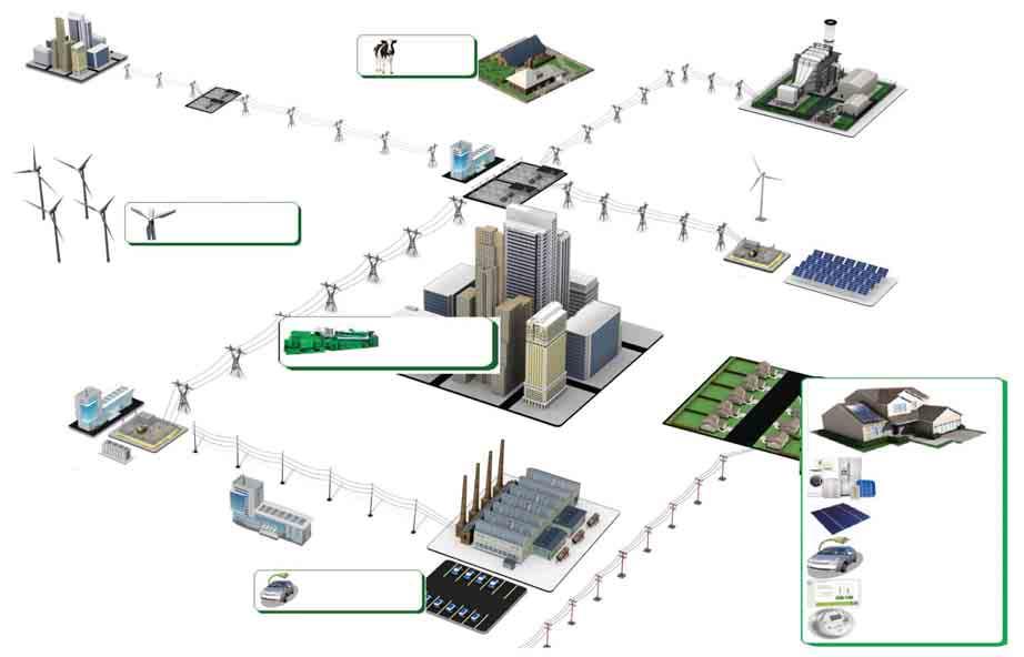

76 Transmission Substation 76


77 SIC-A Redundancy Protocols Gateway (PRP/HSR) Introduction to SIC-A The use of information and communication technologies is globally increasing by the industry, as a base of a predictive maintenance and installations monitoring. A traditional point of view about the energy sector was focused on a generation, transmission and distribution in a lineal way, where the communication was concentrated on the substation. The substations devices shared the information with the control center in-situ using serial protocols. With these protocols, the information was limited and it was insecure. Autoalimentados & Alimentación Dual With the Smart Grid concept evolution, the energy generation is not restricted by specific generation centers. A huge radial infrastructure requires an advanced communication infrastructure. This concept includes not only the latest Ethernet protocols; also the redundant protocols become indispensable. This technology implies an important technology leap for the industry, due to the transmission of a huge amount of data, in many cases in real time, is required. Smart Grid Communication Solutions Provides any-to-any protocol conversion that permit the integration of equipment with proprietary and legacy protocols in a modern infrastructure with the most recent protocols and redundant topologies, including DLMS protocol required for Smart Metering. To implement these new technologies the industry requires an easy and flexible system that is able to adapt to its all requirements. The protocols gateways provide an easy way to adapt the existing devices to the new technologies. The communication redundancy is necessary when the loss of information is not acceptable. The Redundancy methods have evolved significantly, from the basic method of duplicating devices to the most advanced redundant protocols like HSR (High-availability Seamless Redundancy). Most complete topology Different topologies are possible combining the different redundancy possibilities (PRP/HSR) and the protocol conversion function. 77

78 SIC-A Redundancy Protocols Gateway (PRP/HSR) Main characteristics SIC-A provides any-to-any protocol conversion that permit the integration of equipment with proprietary and legacy protocols in a modern infrastructure with the most recent protocols and redundant topologies. SIC-A can work as a multi-protocol conversor, as an unmanaged Redbox or as a redundant protocol gateway. SIC-A can manage upto 3000 data points of the most common protocols (Modbus, IEC 60870, DLMS, DNP3, ) or upto 800 data points of advanced protocols as IEC The device provides with HSR (High-availability Seamless Redundancy) is one of the chosen redundancy protocols for the substation automation as per the IEC standard. This redundancy is the evolution of the existing Parallel Redundancy Protocol (PRP). It is especially suited for applications that demand high availability and very short switch over time because it provides zero recovery time in case of the failure of any component. A good example of application may be the protection of automatized electrical substations or the control of synchronized drives, for instance. Main applications Redbox SIC-A Working as a Redbox allows the connection of HSR networks with traditional ones. In case of PRP redundancy, SIC-A is not denominated Redbox, it would be a device that allows the integration into 2 independent networks through a 3rd Ethernet port. IEC MODBUS RTU (RS-485) e Protocolos RedBox B A 78 HSR IEDs Redbox
79 Protocol Gateway SIC-A device is able of communicating through serial communication RS-232 or RS-485 with multiple equipment with a Master serial protocol (Modbus, IEC , IEC , DLMS ) and dispose the information into an Ethernet protocol as IEC or IEC This way, devices with conventional protocols can be integrated in Ethernet networks with advanced protocols. MODBUS RTU (RS-232) Gateway IEC MODBUS RTU (RS-485) IEDs Gateway de Protocolos Protocol Gateway Redundant Protocol Gateway It is the result of the combination of the functionality of a Gateway and the HSR redundancy. With this configuration, SIC-A allows the integration of equipment with serial communications in a HSR redundant network with an advanced protocol as IEC or IEC MODBUS RTU (RS-232) HSR Gateway IEC (HSR) IEC (HSR) MODBUS RTU (RS-485) HSR IEDs Redundant Protocol Gateway Most complete topology 2 SIC-A in their topology of Redbox allow connecting a HSR redundant network with another PRP network. This is a useful application that permits to coexist new networks with existing ones. In the same way, SIC-A in its topology of PRP Gateway, would allow to integrate serial equipment with conventional protocols in a PRP network with an advanced Ethernet protocol as IEC61850, IEC , etc. 79
80 Technical specifications Item Unit Value Purpose of device - Protocol Gateway Redbox Protocol Redundant Gateway Assembly (mounting) type - Mounted on standard 35 mm DIN bar and Wall mounting Protection degree - IP20 Operating temperature range C -40 to +85 Consumption W 6 maximum Auxiliary Power Vdc/Vac 24*-110 / ±20% Weight Kg 1 Diameter of adapters on terminals mm Main specifications Management Easy Connect Configuration utility System Protocols TCP/IP, UDP/IP, SMTP, POP, HTTP, FTP, SNMP, ICMP, DHCP, BOOTP, Telnet, DNS, ARP, PPPoE, DDNS Device Security NERC/CIP Compliant, SSHv2 Communication Security SSL based VPN tunnel using Blowfish/AES/3DES Logic Programming AND/OR/NOT/Bit SHIFT/Split/Index support for digital and analog data, Delay operations Network Management SNMP Agent Protocol Support IEC /103/104, DNP3 serial/tcp, Modbus RTU/ASCII/TCP, IEC DLMS, IEC 61850, IEC Supported Data Point IEC 61850: 800 DNP3, IEC 60870, Modbus and other proprietary protocols: 3000 Devices Supported 20 (10 over serial RS-485 recommended) Serial interfaces 1 or 2 RS Terminals and/or 1 or 2 RS-232- DB9 * Ethernet interfaces 1 RJ45 or 1 LC SFP 100Base-FX 1300nm * HSR/PRP interfaces** 2 RJ45 or 2 LC SFP 100Base-FX 1300nm * Time Synchronization NTC/SNTP/MEA, Protocol Specific (IEC 104,/DNP3, etc.) RTC on-board Redundancy** Unmanaged. Compliant implementation of both PRP (IEC ) and HSR (IEC ). * Model dependent ** Redundant functionality and redundant ports will be disabled if SIC-A2 model is selected Dimensions and cutout pattern SIC-A 80
81 Selection & Ordering data SIC-A SIC-A Redundancy Protocols Gateway (PRP/HSR) Advanced protocol Gateway with redundancy C B A B C D E F G H 2 A B C D E F 2 A FUNCTION Redbox Protocol Gateway Redundant Protocol Gateway POWER SUPPLY 24*-110 / Vdc-Vac ±20% ETHERNET PORT RJ45 RJ45 + SFP LC Connector REDUNDANCY PORT RJ45 RJ45 + SFP LC Connector SERIAL PORTS RS232 (DB9) + RS-485 (Terminal) REDUNDANCY TYPE None HSR PRP MASTER / CLIENT PROTOCOL None Modbus RTU IEC DNP3.0 Serial IEC DLMS/COSEM IEC IEC Protocols SLAVE/SERVER PROTOCOL None IEC DNP3.0 TCP/IP IEC MODBUS TCP/IP IEC Protocols ADAPTATION - * SIC-A Gateway using optical fiber will require a minimum voltage supply of 48 Vdc for its correct working. SIC A 2 C 0 0 B 0 B C A SIC A 2 C 0 0 B 0 B C A 81


82


83
84 PROTECTION & CONTROL Index ELECTRONIC PROTECTION & CONTROL OF MOTORS, GENERATORS AND PUMPS Introduction.... Motor Management System (Protection, Control & Monitoring) - PBM Series... Motor Protection Relays - GL Series.... Motor Protection Relays - C & G Series... Pump Protection Relays - PS, P and PF Series... Panels for Submersible Pumps - CBM, CBT and CBS Series... Generator Protection Relays - GEN Series... Soft Starters and Motor Controllers - ES Series.... Thermistor Sensors - PTC Series... Installation & Adjustment Guide... Selection Guide CONTROL & MEASUREMENT Introduction.... Phase & Temperature Protection relays Phase Protection - S Series... Phase & Temperature - ST, ST-D Series.... Temperature Relays LIFTS - T2 & TST24 Series... Thermistor Relays - MT2 Series... Voltage Control Relays - U1 & U3 Series... Control Relays Selection Guide... Timers - MTR10 Series
85 3 Three year guarantee EARTH LEAKAGE PROTECTION Introduction.... Earth Leakage Relays WITH BUILT-IN Toroidal Transformer - ELR-A and ELR-T Series... Earth Leakage Relays WITHOUT BUILT-IN transfomer - ELR-B, ELR-3C, D30, DM30 and DR30 Series TRANSFORMERS Introduction.... Protection & Measurement for Low Voltage CT Series... Electric Energy Measurement for Remote Management in Low Voltage CT80II, CT4II, CT80 ABR and CT60II EXT Series... Protection & Measurement for Low Voltage CT Totoidal Series... Earth leakage Protection & Measurement for Low Voltage CT-1 and CTD-1 Series... Current Limiting & Filtering CLR Series... Voltage transformation for Low Voltage PT Series SURGE PROTECTION Introduction.... Power Supply Systems & Installations - VP Series... Type B (Class I).... Type B+C (Class I+II).... Type C (Class II)... Photovoltaic Applications - VP Series.... Wind Power Applications - VP Series.... Protection against Transient Overvoltage - SST Series CUSTOMIZED PRODUCTS AND BRANDLABELING Customized products and Brandlabeling
86


87 ELECTRONIC PROTECTION & CONTROL OF MOTORS, GENERATORS AND PUMPS Introduction Fanox designs and manufactures the most reliable protection & control relays in the market. Products that efficiently prevent engine burnouts, saving costly repairs and preventing dreaded and unnecessary downtime in any important process. The electric motor is one of the most important drives in industry, and plays a decisive role in the success of a production process. Valuable production processes and high value machinery can be completely paralyzed by one single motor failure. This poses the risk of great expenses, with the resulting costs significantly exceeding the cost of repairing the motor itself. Experience shows that motor protection is still a novelty, and still not a priority amongst users. The high numbers of faults that occur every day are mainly due to overloads, locked rotor, phase failure or imbalance, heavy bursts of long duration or high duty cycle of operations, or overheating. Over 60% of failures are due to causes not detected by conventional protection systems, causing excessive heat in the windings, leading to a drastic reduction of the electrical life of the motor. The most significant technical advantages of Fanox designed equipment is: Continuous Thermal image memory of heating and cooling cycles of the engine s starting cycles, work overload and stoppages. The prompt detection of phase loss, even with the engine running at low loads, stopping quickly to avoid costly breakdowns. Identification of trip cause. The relays indicate the reason for tripping instantly allowing you to identify and act quickly on faults. 87


88 PBM PBM Protection, Control and Monitoring System MOTOR MANAGEMENT SYSTEM PBM B PROTECTION FUNCTIONS INTEGRAL SOLUTION FOR MCCs ADAPTABLE TO EVERY CUSTOMER NEEDS MULTIFUNCTION FAULT REPORTS 4 fault reports with the following information: dates, measurements, status bits, inputs and outputs. SELF-DIAGNOSIS, INSTALLATION MONITORING AND STATISTICS Earth toroidal disconnection monitoring. PTC sensor open circuit and short circuit detection. Magnetic module hardware monitoring. Non-volatile memory stored information coherence. Number of motor start ups. Medium and maximum current of last start up. Number of faults for the following functions: Overload, PTC, JAM, locked rotor and neutral faults. Operating hours counter. TEST MENU Operation check on LEDs and outputs. DESIGNED FOR SCADA APPLICATIONS RTU Modbus protocol and RS485 communication MODULAR AND SCALABLE The basic functions of the system can be extended with different modules (PBM H, PBM D...) COMMUNICATION SOFTWARE PBCom PBM H Overload with thermal image Overheating protection (PTC sensor) Phase imbalance or phase failure Phase sequence JAM detection Locked rotor detection Instantaneous earth leakage overcurrent Earth leakage inverse time overcurrent Instantaneous neutral overcurrent Neutral inverse time overcurrent Undercurrent PBM B BASE MODULE Current measurement is obtained from the motor line through the magnetic module without need of external current transformers. From 0,8 up to 25 A with internal current transformers. Over 25 A with external current transformers. MODELS PBM-B1 PBM-B5 PBM-B11 PBM-B12 PBM-B51 PBM-B52 Adjustment range Ib (A) 0,8-6A 0,8-6A 4-25A 4-25A Auxiliary supply 110/230Vac-dc 24/48Vdc 110/230Vac-dc 24/48Vdc Frequency 50/60/ variable (45-65) Hz Maximum motor nominal voltage Vac CODE For N of the motor below the minimum setting B For N of the motor above the maximum setting B Pass the cables several times (n) through the holes in the relay B = n x N Use 3 CT.../5 and the relay PBM B and pass the secondary through the holes OTHERS CHARACTERISTICS Optional PBM-H display module HMI Inputs 1 x PTC temperature sensor, 1 x Toroidal transformer (external earth fault), 1 x Digital input 24 Vdc Outputs 2 x NO-NC contact Short circuit withstand rating 5000 A to 0,5s (SCR 5000@0,5s) Communication RS485 ModBus RTU Signalling 5 signalling LEDs Reset mode Manual, automatic and automatic time delayed Test Specific test menu Operating temperature - 10ºC + 60ºC 88


89 PBM H DISPLAY MODULE HMI This is an optional display module with an LCD screen for signalling, control and setting. The LEDs can be configured and are identified by labels. Access to menus is intuitive and direct, making protection system commissioning easier. CODE ACCESORIES LANGUAGE PBM-HS display Spanish PBM-HS display French PBM-HS display English PBM-HS display Polish PBM-HS display German CD PBM CDCNB CABLE 0,5 M CDCN1 CABLE 1 M CHARACTERISTICS PBM H LCD Display Keyboard Communication Signalling Reset mode Test 20 x 2 alphanumeric characters 9 keys RJ45 connector to relay 6 configurable signalling LEDs Manual, automatic and automatic time delayed Specific test menu FUNCTION DIAGRAM PBM B DIMENSIONS (mm) PBM B PBM H Ø CONNECTION DIAGRAM PBM B PBM Motor Management System Video demo: 89
, even at reduced load. Visual indication of tripping cause.")
90 GL Motor Protection Relays INTEGRAL MOTOR PROTECTION For 3-phase motors from 1 to 630 A and over. Cable feed through relay. Precise motor heating and cooling memory, reproduces its thermal image. Immediate detection of phase loss (3 s), even at reduced load. Visual indication of tripping cause. For motors (1 to 630 A and over), in applications such as surface mounted pumps, compressors, mixers, ventilators, elevators, cranes, industrial refrigeration and in general for those motors requiring complete protection where over temperature (by means of PTC sensor) and incorrect phase sequence protection is required. Its 7 trip classes cover all types of starting or working cycles. GL PROTECTION FUNCTIONS Overload Phase imbalance or phase loss Overtemperature Phase sequence EXTERNAL DISPLAY MODULE By means of this plug-in optional accessory, the relay status can be seen and reset from the exterior of the electrical panel board. Easy to install. Size of a Ø22 mm push button. Suitable for motor control centres (MCC) and panel boards. ODGL Models Code Relay type ODGL GL MODELS GL 16 GL 40 GL 90 Code Adjustment range Motor 400 V 50/60 Hz according to the relay voltage supply (+15% -10%) ac: 50/60 Hz For N of the motor below the minimum setting B For N of the motor above the maximum setting B External display module (optional) I B (A) 4-16, , CV kw 2,2-7,5 7,5-18, Vac single phase Vac single phase Vac, dc single phase Pass the cables several times (n) through the holes in the relay B = n x N Use 3 CT.../5 and the relay GL16 and pass the secondary through the holes ODGL CHARACTERISTICS Thermal memory / Overload trip Yes / From 1,1 x B Maximum motor nominal voltage 1000 Vac Trip classes (IEC ) Phase sequence protection ON OFF Actuates during the motor start Phase imbalance protection Over 40%. Tripping time < 3s PTC Min/max cold resist.-average trip / reset resist. 25Ω / 1500Ω Ω / 1800Ω Reset mode Manual and remote Signalling LED s 4 LED s: ON Output contacts 1 relay with 1 NA + 1 NC Switching power th : 5A; AC15-250V - 2A; DC13-30V - 2A Terminals: Max. section / screw torque 2,5 mm 2, No AWG / 20Ncm, 1.8 LB - IN Power consumption 2,5 VA ( Vac) - 1,5 W (24 Vdc) Protection degree / weight / mounting IP20 / 0,5 kg / DIN rail Storage temperature -30 C +70 C Operating temperature / max. altitude -15 C +60 C / 1000m ; -15 C +50 C / 3000m Standards IEC 255, IEC 947, IEC 801, EN Settings and curves, see pages 105 to 111. L3 L2 L1 DIMENSIONS GL RELAY (mm) DIMENSIONS ODGL MODULE (mm) Ø 22,5 WIRING DIAGRAMS T1 T2 PTC 78 17,5 17,5 U1 V1 W1 M T1 T2 A1 K1 A2 Ø 30, ,3 20,0 13-K1 14-K A A2 L1 N 80 35, = 2 m Tripped or Us= Normal
, even at reduced load. Visual indication of tripping cause.")
91 INTEGRAL MOTOR PROTECTION For 3-phase motors from 60 to 200 A and over. Cable feed through relay. Precise motor heating and cooling memory, reproduces its thermal image. Immediate detection of phase loss (3 s), even at reduced load. Visual indication of tripping cause. For 3 phase motors up to 200A, in applications such as surface mounted pumps, compressors, mixers, ventilators, elevators, cranes, industrial refrigeration and in general for those motors requiring complete protection where over temperature (by means of PTC sensor) and incorrect phase sequence protection is required. Its 7 trip classes cover all types of starting or working cycles. GL 200 PROTECTION FUNCTIONS Overload Phase imbalance or phase loss Overtemperature Phase sequence EXTERNAL DISPLAY MODULE By means of this plug-in optional accessory, the relay status can be seen and reset from the exterior of the electrical panel board. Easy to install. Size of a Ø22 mm push button. Suitable for motor control centres (MCC) and panel boards. ODGL Models Code Relay type ODGL GL MODELS GL 200 Code Adjustment range Motor 400 V 50/60 Hz according to the relay voltage supply ac: 50/60 Hz I B (A) CV kw % 230 Vac single phase % 115 Vac single phase % 24 Vac, dc single phase External display module (optional) ODGL DIMENSIONS GL RELAY (mm) Ø CHARACTERISTICS Thermal memory / Overload trip Yes / From 1,1 x B Maximum motor nominal voltage 1000 Vac Trip classes (IEC ) Phase sequence protection ON OFF Actuates during the motor start Phase imbalance protection Over 40%. Tripping time < 3s PTC Min/max cold resist.-average trip / reset resist. 25Ω / 1500Ω Ω / 1800Ω Reset mode Manual and remote Signalling LED s 4 LED s: ON Output contacts 1 relay with 1 NA + 1 NC Switching power th : 5A; AC15-250V - 2A; DC13-30V - 2A Terminals: Max. section / screw torque 4.0 mm 2, No AWG / 50Ncm, 4.4 LB - IN Power consumption 2,5 VA ( Vac) - 1,5 W (24 Vdc) Protection degree / weight / mounting IP20 / 1 kg / DIN rail Storage temperature -30 C +70 C Operating temperature / max. altitude -15 C +60 C / 1000m ; -15 C +50 C / 3000m Standards IEC 255, IEC 947, IEC 801, EN L3 L2 L1 WIRING DIAGRAMS T1 T2 U1 V1 W T1 T2 A1 K1 A2 13-K1 14-K A A2 45 L1 N Tripped or Us= Normal Settings and curves, see pages 105 to 111. PTC M 91
, even at reduced load. Visual indication of tripping cause.")

92 C Motor Protection Relays BASIC MOTOR PROTECTION For 3-phase motors from 1 to 630 A and over. Cable feed through relay. Precise motor heating and cooling memory, reproduces its thermal image. Immediate detection of phase loss (3 s), even at reduced load. Visual indication of tripping cause. For motors of low and medium power in several applications such as compressors, ventilators, surface mounted pumps, conveyor belts, machine tools, and in general to protect motors which need dependable and accurate protection relays for every type of start. Its 3 trip classes cover many types of starting or working cycles. C PROTECTION FUNCTIONS Overload Phase imbalance or phase loss EXTERNAL DISPLAY MODULE By means of this plug-in optional accessory, the relay status can be seen and reset from the exterior of the electrical panel board. Easy to install. Size of a Ø22 mm push button. Suitable for motor control centres (MCC) and panel boards. ODC Models Code Relay type ODC C MODELS C 9 C 21 C 45 Code Adjustment range Motor 400 V 50/60 Hz according to the relay voltage supply (+15% -10%) ac: 50/60 Hz For N of the motor below the minimum setting B For N of the motor above the maximum setting B External display module (optional) I B (A) 3-9,3 9-21, ,2 CV 2-5,5 7, kw 1,5-4 5, Vac single phase Vac single phase Vac, dc single phase Pass the cables several times (n) through the holes in the relay B = n x N Use 3 CT.../5 and the relay C9 and pass the secondary twice through the holes CHARACTERISTICS Thermal memory / Overload trip Yes / From 1,1 x B Maximum motor nominal voltage 1000 Vac Trip classes (IEC ) Phase imbalance protection Over 40%. Tripping time < 3s Reset mode Manual and remote Signalling LED s 3 LED s: ON + + Output contacts 1 relay with 1 NO + 1 NC Switching power th : 5A; AC15-250V - 2A; DC13-30V - 2A Terminals: Max. section / screw torque 2,5 mm 2, No AWG / 20Ncm, 1.8 LB - IN Power consumption C9: 6,5VA (230Vac) - 3VA (115Vac) / C21-C45: 2,5VA Protection degree / weight / mounting IP20 / 0,3 kg / DIN rail Storage temperature -30 C +70 C Operating temperature / max. altitude -15 C +60 C / 1000m ; -15 C +50 C / 3000m Standards IEC 255, IEC 947, IEC 801, EN Settings and curves, see pages 105 to 111. ODC L3 L2 L1 DIMENSIONS C RELAY (mm) DIMENSIONS ODC MODULE (mm) Ø 22,5 39 WIRING DIAGRAMS Ø 30,0 13 A1 K1 14 A ,3 20,0 A2 35,4 13-K1 14-K A L = 2 m N Tripped or Us= Normal M 92

93 G EEx e Motor Protection Relays MOTOR PROTECTION IN EXPLOSIVE OR HAZARDOUS AREAS Certificates for use as category 3 - Directive ATEX 94/9/EC. For 3-phase motors up to 1000 Vac. Currents from 1,5 to 630 A and over. With thermal memory. Visual indication of tripping cause. These relays are applicable for EEx e motors with ratings up to 630A and above, operating in potentially explosive or hazardous areas such as petrochemical industries, plastic factories, etc. The relay is installed outside the explosive area. G PROTECTION FUNCTIONS Overload Phase imbalance or phase loss Overtemperature The models G and BG are ATEX marked with certification for Category 3 use. PTB approval: G and BG relays have been approved by the Physikalisch-Technische Bundesanstalt- PTB for the protection of EEx e explosion proof motors (DIN EN / DIN VDE 0170 /DIN VDE 0171 part 6) according to the stipulations and requirements of PTB. PTB report no. PTB Ex / /00 MODELS G 17 Code Adjustment range Motor 400 V 50/60 Hz according to the relay voltage supply (+15% -10%) ac: 50/60 Hz I B (A) 5-17,7 CV 3-10 kw 2,2-7,5 230 Vac single phase Vac single phase Vdc, ac DIMENSIONS G RELAY (mm) For N of the motor below the minimum setting B For N of the motor above the maximum setting B External display module / Code no. Pass the cables several times (n) through the holes in the relay B = n x N Use 3 CT s.../5 and pass their secondary twice (n=2) through the relay holes No 17,5 17, ,4 38 CHARACTERISTICS Thermal memory / Overload trip Yes / From 1,1 x B Maximum motor nominal voltage 1000 V 15 adjustable tripping curves Cold tripping times at 6 x B from 2 to 30s Phase imbalance protection Over 40%. Tripping time < 3s PTC min/max cold resist. / Average trip resistance 100 Ω / 1500 Ω Ω Reset mode Manual and remote Signalling LED s 4 LED s: ON + one for each protection Alimentación auxiliar monofásica Voltage Us Vac (+15% -6%) / 24 Vdc (±10%) Frequency 50/60 Hz (from 49 to 61,2 Hz) Consumption 2,5 VA ( Vac) / 1,5 W (24 Vdc) Protection fuse GL 6 A Output contacts 1 relay with 1 NO + 1 NC Switching capacity in abnormal conditions I th: 5A; AC15-250V - 2A; DC13-30V - 2A Short-circuit resistance 1000 A Short circuit withstand rating 5000 A at 0,5 s (SCR 5000@0,5 s) Terminals max. section / Screw torque 2,5 mm 2, No AWG / 20Ncm, 1.8 LB - IN Protection degree / weight / mounting IP20 / 0,5 kg / DIN rail Storage temperature -30 C +70 C Operating temperature -15 C +60 C Standards EN , EN , EN , EN , EN 60529, EN , UL 508 EN , EN , EN , EN 954-1, EN , EN , EN L3 L2 L1 WIRING DIAGRAM T1 T2 PTC U1 V1 W1 M T1 T2 A1 K1 A2 13-K1 14-K A A2 L1 N Tripped or Us= Normal Settings and curves, see pages 105 to

94 PS SINGLE PHASE Pump Protection Relay without Level Sensors SINGLE PHASE PUMP PROTECTION Underload protection by undercurrent Eliminates need for level sensors to detect dry running. For 1-phase motors from 3 to 16 A. Precise motor heating and cooling memory, reproduces its thermal image. Visual indication of trip cause. Adjustable reset time for. PS 11-R PROTECTION FUNCTIONS Overload Undercurrent Overvoltage Suitable for 1-phase submersible pumps. By monitoring undercurrent it avoids problems caused by dry running, cavitation, etc. The great advantage of the PS relay is that, without requiring any external detectors like level electrodes, it monitors the load of the motor and stops it before an expensive breakdown occurs. WITHOUT LEVEL SENSORS WITHOUT LEVEL SENSORS PS 16-R MODELS PS 11-R PS 16-R Code Adjustment range Motor 400 V 50/60 Hz according to the relay voltage supply (+15% -10%) ac: 50/60 Hz I B (A) CV 0,5-2 0,5-3 kw 0,37-1,5 0,37-2,2 230 Vac single phase Vac single phase DIMENSIONS PS RELAY (mm) PS 11-R 22,5 72, ,4 61,5 CHARACTERISTICS Thermal memory / Overload trip Yes / From 1,1 x B Maximum motor nominal voltage 230 Vac Trip classes (IEC ) 10 Undercurrent protection adjustable / Trip delay From 0,4 to 0,9 x B / 5 s Overvoltage protection From nominal V + 15% Reset mode for protection against dry running automatic (adjustable) and remote. More info in page 110 Reset mode for other protection functions automatic and remote, automatic. More info in page 110 Signalling LED s 3 LED s: ON + + Output contacts 1 relay with 1 NO Switching power I th : 5A; AC15-250V - 2A; DC13-30V - 2A Terminals: Max. section / screw torque 2,5 mm 2, No AWG / 20Ncm, 1.8 LB - IN Power consumption 7 VA (230 Vac) - 4 VA (115 Vac) 3 VA ( Vac) Protection degree / weight / mounting IP20 / 0,15 kg / DIN rail IP20 / 0,3 kg / DIN rail Storage temperature -30 C +70 C Operating temperature / max. altitude -15 C +60 C / 1000m; -15 C +50 C / 3000m Standards IEC 255, IEC 947, IEC 801, EN Settings and curves, see pages 105 to 111. PS 16-R 8 WIRING DIAGRAM 8 N (1) IIN (1) IOUT L 39 A1 A A1 K1 A (1) 5 Tripped or Us= Normal , PS 16-R: pass the wire through the hole of the relay. M 94

95 P THREE PHASE Pump Protection Relay without Level Sensors THREE PHASE PUMP PROTECTION Underload protection by undercurrent Eliminates need for level sensors to detect dry running. For 3-phase motors from 1 to 630 A and over. Cable feed through. Precise motor heating and cooling memory, reproduces its thermal image. Visual indication of tripping cause. Manual, remote and automatic reset. Suitable where the undercurrent (running without load) is critical, such us submersible pumps, surface pumps, etc. In these cases, when the equipment runs without load (dry well) the relay trips by undercurrent. The great advantage of the P relay is that, without requiring any external detectors such as level electrodes, it monitors the load of the motor and stops it before an expensive breakdown occurs. EXTERNAL DISPLAY MODULE By means of this plug-in optional accessory, the relay status can be seen and reset from the exterior of the electrical panel board. Easy to install. Size of a Ø22 mm push button. Suitable for motor control centres (MCC) and panel boards. P ODP Models Code Relay type ODP P PROTECTION FUNCTIONS Overload Undercurrent WITHOUT LEVEL SENSORS WITHOUT LEVEL SENSORS Phase imbalance or phase loss Phase sequence MODELS P 19 P 44 P 90 Code Adjustment range Motor 400 V 50/60 Hz according to the relay voltage supply (+15% -10%) ac: 50/60 Hz I B (A) 7-19, , ,4 CV ,5-27,5 27,5-55 kw 3-7,5 9, Vac single phase Vac single phase Vac, dc single phase DIMENSIONS P RELAY (mm) For N of the motor below the minimum setting B Pass the cables several times (n) through the holes in the relay B = n x N For N of the motor above the maximum setting B Use 3 CT.../5 and the relay P 19 External display module (optional) CHARACTERISTICS Thermal memory / Overload trip Yes / From 1,1 x B Maximum motor nominal voltage 1000 Vac Trip classes (IEC ) Phase sequence protection Yes Phase imbalance protection Over 40%. Tripping time < 3s Undercurrent protection adjustable / Trip delay From 0,5 to 0,9 x B. Operative from 0,3 x B / 3s Reset mode for protection against dry running manual, remote and automatic. More info in page 110 Reset mode for other protection functions Manual, remote and automatic (every 15 minutes) Short circuit withstand rating 5000 A at 0,5 s (SCR 5000@0,5 s) Signalling LED s 4 LED s: ON Output contacts 1 relay with 1 NO + 1 NC Switching power I th: 5A; AC15-250V - 2A; DC13-30V - 2A Terminals: Max. section / screw torque 2,5 mm 2, No AWG / 20Ncm, 1.8 LB - IN Power consumption 2,5 VA Protection degree / weight / mounting IP20 / 0,5 kg / DIN rail Storage temperature -30 C +70 C Operating temperature / max. altitude -15 C +60 C / 1000m; -15 C +50 C / 3000m Standards IEC 255, IEC 947, IEC 801, EN Settings and curves, see pages 105 to 111. ODP L3 L2 L1 17,5 17,5 DIMENSIONS ODP MODULE (mm) Ø 22,5 WIRING DIAGRAM P U1 V1 W1 M A1 K1 A2 Ø 30,0 5 11,3 20,0 13-K1 14-K A1 P A2 35, L1 N 1 = 2 m Tripped or Us= Normal

96 PF THREE PHASE Pump Protection Relay without Level Sensors THREE PHASE PUMP PROTECTION Underload protection by cos Eliminates need for level sensors to detect dry running. For 3-phase motors from 1 to 630 A and over. Cable feed through relay itself. Precise motor heating and cooling memory, reproduces its thermal image. Visual indication of tripping cause. Adjustable reset time for cos. Suitable for 3-phase submersible pumps, petrol station pumps, and other type of pumps and systems where running without load is critical (dry well, broken transmission belt, etc.). The great advantage of these relays is that, by using the motor itself as a sensor and without requiring any external detectors, they monitor the cos of the motor and stop it before a breakdown caused by dry running, cavitation or closed valve occurs. PF PROTECTION FUNCTIONS Overload cos Underload WITHOUT LEVEL SENSORS WITHOUT LEVEL SENSORS Phase imbalance or phase loss Phase sequence MODELS PF 16-R PF 47-R Code Adjustment range Motor 400 V 50/60 Hz Adjustment range Motor 230 V 50/60 Hz according to the relay voltage supply (+15% -10%) ac: 50/60 Hz I B (A) 4-16, ,5 CV kw 2,2-7,5 7,5-22 I B (A) 4-16, ,5 CV 1,5-5,5 5,5-15 kw 1, /440 Vac 3-phase (motor) Vac 3-phase (motor) For N of the motor below the minimum setting B For N of the motor above the maximum setting B External display module (optional) CHARACTERISTICS Thermal memory / Overload trip Pass the cables several times (n) through the holes in the relay B = n x N Yes / From 1,1 x B Use 3 CT.../5 and the relay PF16-R ODPF Maximum motor nominal voltage 440 Vac Trip classes (IEC ) Phase sequence protection Yes Phase imbalance protection Over 40%. Tripping time < 3s Underload protection by cos / Trip delay cos adjustable from 0,15 to 1,0 / adjustable from 5 to 45s Reset mode for protection against dry running cos automatic (adjustable) and remote. More info in page 110 Reset mode for other protection functions Manual, remote and automatic. More info in page 110 Signalling LED s 4 LED s: ON + + cos + Output contacts 1 relay with 1 NO + 1 NC Switching power I th : 5A; AC15-250V - 2A; DC13-30V - 2A Terminals: Max. section / screw torque 2,5 mm 2, No AWG / 20Ncm, 1.8 LB - IN Power consumption 1,5W - 12 VA (230 Vac) - 20 VA (400 Vac) Protection degree / weight / mounting IP20 / 0,5 kg / DIN rail Storage temperature -30 C +70 C Operating temperature / max. altitude -15 C +60 C / 1000m; -15 C +50 C / 3000m Standards IEC 255, IEC 947, IEC 801, EN Settings and curves, see pages 105 to 111. DIMENSIONS PS RELAY (mm) PF 16-R PF 47--R 12 Ø ,5 17,5 WIRING DIAGRAM L3 L2 L1 PF U1 V1 W1 M 3 56, K1 14-K1 L L2 L3 PF A1 K1 14 A2 N 80 35, , L1 Tripped or Us= Normal
97 EXTERNAL DISPLAY MODULE By means of this plug-in optional accessory, the relay status can be seen and reset from the exterior of the electrical panel board. Easy to install. Size of a Ø22 mm push button. Suitable for motor control centres (MCC) and panel boards. This optional display module is mounted externally, e.g. on the panel door or a draw-out unit in a motor control centre (MCC) and connected to the relay by a flat cable (length 2 meters). The module has the appropriate LED s to signal the trip cause and a reset push-button. Weight: 0,05 kg. Protection degree: IP50 The PS and PF electronic relays have been specially designed to provide complete protection for both single and three phase pumps and any other system where dry running is a critical factor. Fanox panel Electronic relay Conventional panel Thermal relay Level electrode relay as well as Level electrodes Level electrode wiring COST COMPARISON ODPF Euros Conventional panel Fanox panel Model Code Relay type ODPF PF DIMENSIONS ODPF MODULE (mm) Ø 22,5 Ø 30,0 11,3 20,0 1 = 2 m Depth of well The graph shows that with FANOX SOLUTION you can save up to 35% of the cost of a pump protection system. 97

98 CBM Panels for SUBMERSIBLE Pumps SINGLE PHASE PUMPS Thermal memory of motors heating and cooling cycles. Automatic reset, adjustable from 2 to 240 minutes for well filling, Indication of trip cause. Control point for pressure switch, buoy, programmer... Includes: circuit breaker 1P+N, PS-R electronic relay, contactor, LEDs and on/off switch. One of the most critical situations in pump operation is dry running. The solution offered by FANOX single-phase protection panels is based on measuring the undercurrent. In dry running situations a current decrease is detected. This reduction of consumed current is measured by the PS-R electronic relay fitted to the protection panel: when the preset undercurrent value is reached, it switches the pump off. IP 55 WITHOUT LEVEL SENSORS WITHOUT LEVEL SENSORS CBM PROTECTION FUNCTIONS Overload Undercurrent Overvoltage Short-circuit Pump protection without level sensor video demo: Models Code Approx. motor current (Amps) Power of single-phase 230 V motor HP kw Adjustable well filling time (minutes) Dimensions (mm) CBM x 250 x 150 CBM x 250 x 150 CBM x 250 x 150 Equipment with halogen-free wiring Fanox Control Panels protect pumps against dry running without using level sensors. Maximum protection without level electrodes or level relays. Electronic relay incorporated. Quick and easy installation, maintenance-free. Installation costs are significantly reduced. Can be adapted to installations already in service, without removing the pump. WITHOUT LEVEL SENSORS 98

 is the value of the cosine of the phase angle between the voltage and the intensity of the electrical current.")
99 CBT Panels for SUBMERSIBLE Pumps THREE PHASE PUMPS Thermal memory of motors heating and cooling cycles. Automatic reset for well filling. Adjustable from 2 to 75 minutes. Trip cause indication. Control point for pressure switch, buoy, programmer... Includes: circuit breaker 3P or 3P+N, PF-R electronic relay, contactor, LEDs and on/off switch. Models with metal enclosure also include voltmeter, ammeter and meter. The cosine of phi (Cos ) is the value of the cosine of the phase angle between the voltage and the intensity of the electrical current. This oscillates from a value slightly below 1 for a full load operating motor to almost 0 when it is dry running. Therefore, in dry running situations, cos falls significantly. This reduction is monitored by the PF-R relay installed in FANOX three-phase protection panels, meaning that when it falls beneath the adjusted value, the panel shuts down the pump and protects it from damage. IP 55 WITHOUT LEVEL SENSORS WITHOUT LEVEL SENSORS CBT CBT-M PROTECTION FUNCTIONS cos Underload Overload Phase imbalance or phase loss Phase sequence Short-circuit Models Code Approx. motor current (Amps) Power of three-phase 400 V motor HP kw Adjustable well filling time (minutes) Dimensions (mm) CBT x250x150 CBT x250x150 PLASTIC CBT x250x150 CBT x250x150 CBT x250x150 CBT x250x150 CBT-20M x250x150 CBT-25M x250x150 METAL CBT-30M x250x150 CBT-40M x500x200 CBT-50M x500x200 CBT-60M x500x200 Equipment with halogen-free wiring 99


100 CBS Panels for SUBMERSIBLE Pumps THREE PHASE PUMPS WITH SOFT STARTER Thermal memory of motors heating and cooling cycles. Automatic reset for well filling. Adjustable from 2 to 75 minutes. Trip cause indication. Control point for pressure switch, buoy, programmer... Metal case. Includes: circuit breaker 3P+N, PF-R electronic relay, ES soft starter, contactor, LEDs and on/ off switch. FANOX protection panels with progressive start up and shut -down are fitted with ES soft starters to prevent problems caused by water hammering or sudden start-ups and shut-downs. Protection against dry running is provided by the PF-R relay that monitors the value of cos and shuts down the pump when it falls below the selected value. IP 55 CBS PROTECTION FUNCTIONS cos Underload Overload Phase imbalance or phase loss Phase sequence Short-circuit Soft start Soft stop WITHOUT LEVEL SENSORS WITHOUT LEVEL SENSORS Models Code Approx. motor current (Amps) Power of three-phase 400 V motor HP kw Adjustable well filling time (minutes) Dimensions (mm) CBS-2* x300x200 CBS-3* , x300x200 CBS-5* x300x200 CBS-7* x400x200 METAL CBS x400x200 CBS x400x200 CBS x400x200 CBS x400x200 CBS x400x200 CBS x500x200 Equipment with halogen-free wiring * Models available in plastic box. 100

101 GEN Generator Protection Relay GENERATOR PROTECTION For generators up to 1000 Vac. With thermal memory. Visual indication of trip cause. Fast trip curves. This relay is specially applicable for protecting low voltage generators up to 1000 Vac, and currents up to 2000 A or higher. Precise motor heating and cooling memory, reproduces its thermal image. It offers a suitable protection offering the choice between 15 trip curves thus avoiding the generator working over its damage curve. GEN PROTECTION FUNCTIONS Overload Phase imbalance or phase loss EXTERNAL DISPLAY MODULE By means of this plug-in optional accessory the relay status can be seen and reset from the exterior of the electrical panel board. Easy to install. Size of Ø22 mm push button. ODGEN OTHER RELAYS FOR GENERATORS: U3N: Three-phase voltage relay (See page 119). Models Code Relay type ODGEN GEN MODELS GEN 10 Adjustment range I B (A) 4-10,3 Auxiliary voltage supply (+15% -10%) 24 Vdc Code For N of the generator above 10,3 A Use 3 current transformers.../5 External display module (optional) ODGEN DIMENSIONS GEN RELAY (mm) CHARACTERISTICS Thermal memory / Overload trip Yes / From 1,1 x B Maximum generator nominal voltage 1000 Vac Trip time t6 x I B 15 adjustable curves from 0,2 to 3 s. Phase imbalance protection Over 20%. Tripping time < 3s Reset mode Manual and remote Signalling LED s 3 LED s: ON + one for each protection Output contacts 1 relay with 1 NO + 1 NC Switching power th :5A; AC15-250V - 2A; DC13-30V - 2A Short circuit withstand rating 5000 A at 0,5 s (SCR 5000@0,5 s) Terminals: Max.section / screw torque 2,5 mm 2, No AWG / 20Ncm, 1.8 LB - IN Power consumption 1,5 W Protection degree / weight / mounting IP20 / 0,5 kg / DIN rail Storage temperature -30 C +70 C Operating temperature / max. altitude -15 C +60 C / 1000m; -15 C +50 C / 3000m Standards IEC 255, IEC 801, EN Settings and curves, see pages 105 to ,5 17,5 DIMENSIONS ODGEN MODULE (mm) Ø 22,5 WIRING DIAGRAM GENERATOR 50 Ø 30,0 n = ,3 20,0 35, = 2 m Tripped or Us= Normal LOAD B= N gener 5xn N trafo 101


102 ES Soft Starters and Motor Controller For three-phase induction motors of up to 22 kw / 400 V. Built in heat dissipater and electro-mechanical bypass relay. Substitutes the conventional contactors. One in direct start-up and three in star-delta start-up cycle. Offers greater life cycle. Lower maintenance cost. No pressure surge when using pumps and compressors. Reduces hammering. Less current and voltage drop during start up. Allows for reduced power consumption. Mechanical dimensioning can be optimised. Simplified automation. Assembly, setting, installation, commissioning and maintenance are made easy by the compact design. Reduces start and stop torque, eliminating mechanical problems. Additional cooling is not necessary thanks to the bypass built-in relay. Substitutes the conventional contactors: one for direct start-up and three for star-delta start-up. ES-3 ES-12 ES-25 ES-45 PROTECTION FUNCTIONS Soft start Soft stop ES -25 and ES -45 model include: Hz Hz Long Phase imbalance or phase loss Overtemperature Phase sequence Overvoltage Undervoltage Overfrequency Overfrequency Overcurrent Long ramp MODELS* ES ES ES ES 230/400-25E ES 230/400-45E ES 230/400-25F ES 230/400-45F Nominal voltage 50/60 Hz V±15% Maximum current A Motor power kw 1,1 3 5,5 5,5/11 11/22 5,5/11 11/22 CV 1,5 4 7,5 7,5/15 15/30 7,5/15 15/30 Code E E F F * Other voltages available upon request. (380V,480V and 600V) CHARACTERISTICS Control voltage (±15%) A1-A2= Vac,dc / A1-A3= Vac A1-A2= Vac A1-A2=24 Vac/dc Degree of protection IP20 Operating temperature -20 C +50 C -20 C +60 C Standards and approvals IEC UL, CSA and CE mark INDICATIONS Supply green POWER ON green POWER ON green Ramps yellow RAMPING yellow RAMPING yellow Bypass relay yellow BYPASS yellow BYPASS yellow Alarm OVERHEAT red OVERHEAT red ADJUSTMENTS Start torque (% of nominal torque) 0-85% 0-70% Start-up time 0,5-5 s 1-10 s Stop time 0,5-5 s 1-30 s speed Torque direct startup L1 L2 L3 resistant torque soft start Uc In Current t Direct start wave forms Soft start wave forms Nominal speed Speed U V W 102


103 OPERATION POTENTIOMETER SETTING MODE OF OPERATION These units represent the best protection against premature ageing of motors and mechanical items. Sudden starts and stops, that can produce damages in the bearings and gears of the motors, are eliminated. They prevent frequent faults and objects falling onto conveyer belts. They reduce mechanical impact in motors, axles, gears and belts, significantly prolonging the operating life of the controlled units. An electronic circuit with semiconductors starts the motor without using the contacts. Hence these do not withstand sparks or erosion. When the minimal voltage of the motor is reached the semiconductors are bypassed by the relay contacts. Thanks to this technology, the ES starters have a longer operating life than conventional contactors. They are easy to install and control. They can operate by means of an external control signal, such as a programmable automation. 100% Motor voltage 1 1 Par: INITIAL TORQUE. Voltage when ramp-up begins. 2 Ramp up time: RAMP UP. 3 Ramp-down time: RAMP DOWN. 2 Time Potentiometers 1 2 and 3 Initially set potentiometers 2 and 3 to maximum. Connect the supply and set potentiometer 1 so that the motor begins to rotate as soon as the supply is applied. Set the ramp-up and ramp-down times to the desired value. 3 a) Change from on line direct start to soft start: 1) Cut off the cable from the motor and insert the ES starter. 2) Connect the control input to two of the input lines. Set the potentiometers according to the settings mode. 3) Reconnect the power supply. On connecting C1, the starter performs a soft motor start. On disconnecting C1, the motor stops, the starter resets to zero and after 0.5 seconds a new soft start up may be performed. b) Soft Start / Soft Stop When S1 is closed (connection diagram), the soft motor start is realised according to the potentiometers setting of initial t and % torque. When S1 is open the soft stop is done in accordance with the ramp down potentiometer setting. APPLICATIONS For three-phase motors in applications such as: Pumps. Cold compressors. Conveyor belts, lifting devices, etc. Mixers. Fans, extractor fans and blowers. Garage doors and elevators. Concrete mixers. Palletizer devices, etc. DIMENSIONS (mm) ES 3-12 ES 25 ES WIRING DIAGRAMS ES ES 400-3, ES - 25E ES - 25F ES - 45E ES - 45F Soft start Soft start / soft stop fig. 1 fig. 2 fig. 3 fig. 4 f ig. 5 fig
104 PTC Thermistor Sensors THERMISTOR SENSORS PTC PTC Connected to PBM B, GL, G, ST or MT relays to protect motors against overtemperature. PTC. Positive Temperature Coefficient PTC 120, and PTC 160 for internal mounting. Temperature threshold 120 C and PTC 160ºC. PTCEX 70, for external mounting. Temperature threshold 70 C. PTCEX 70 Models PTC 120 PTC 160 PTCEX 70 Code 41700/ Threshold temperature 120 C 160 C 70 C Threshold resistance 1330 Ω 1330 Ω 1330 Ω Mounting internal internal external Length in-built (m) 0,5 0,2 0,5 - Length of wire accessory (m) - - 0,5 (17008) 1 (17009) PTC 120 /160 DIMENSIONS PTC (mm) Ø 3 mm Ø 3,7 mm PTC 120 PTC 160 PTCEX
105 Installation and Adjustment guide THE MOTOR PROTECTION The electric motor is one of the most important operating devices in industry. Many times the shutdown of an industrial process is caused by a simple motor. High-cost production runs and valuable machinery can become paralysed at great cost, even more than the cost of rewinding the motor. Experience shows that motor protection continues to be a problem, based on the number of breakdowns occuring every day. Over 60% of failures are caused by overheating of the motor windings. These can be detected, and prevented, by measuring and analysing the current being absorbed by the motor, or by controlling temperature limits of the winding. The major causes are as follows: Overloads Locked rotor Over and undervoltage Phase imbalance or phase loss Long and heavy start-ups Excessive operating cycles Heating from non-electrical causes Inadequate motor ventilation High room temperature Insulation failure The following diagram shows the dramatic decrease suffered in the electric life of a motor due to the excessive heat of the motor windings (Montsinger s rule). Life time hours Overtemperature ( C) FANOX RELAYS Our R+D Division has allowed FANOX to develop a wide range of easy-toinstall and operate electronic relays, at truly competitive prices, which will save downtime and money. FANOX motor protection relays work with the current measured in real time. The current, which is read by three current transformers built into the relays, is electronically processed and used as a model of the thermal image of the motor, and is continously compared to the values set on the relay. The three power supply cables to the motor are not directly connected to the relay, but pass through its corresponding CT holes. This provides motor protection against: Overload: The relay creates a model of the thermal image of the motor during its heating and cooling cycles. In this way, in overload conditions, the relay will take into consideration previous operating conditions of the motor, and will trip quicker if the relay has detected previous occasions of overload. This thermal memory is independent of the auxiliary voltage supply of the relay and is stored even when this voltage is cut off or disconnected. The different trip curves available for selection in the relays allow for precise adjustment to any kind of motor start-up or work ing cycle. Phase imbalance and phase loss: even if the motor is running below its full load current. Incorrect phase sequence detection is highly important when the correct phase sequence is critical as in compressors, pumps, fans and other applications (GL, P, PF). Underload by undercurrent: protects the motor against working without load, very important in pumps (P and PS). Protection against no-load operation: underload protection by cos has been incorporated so that the relay differentiates precisely between very low load and no-load operations, and drops out in the latter case (PF). In addition, when the relay is connected to thermistor sensors (PTC), it protects the motor against electrical and non-electrical overheating (GL, G). A visual display of the cause allows maintenance personnel to identify and immediately act on the underlying causes. The use of the OD display makes this operation much easier. FANOX relays guarantee ideal protection for motors (pumps, compressors, fans, etc). As one can see, a 10ºC increase in temperature reduces the useful life of the motor by half. The most reliable protection options in common use are: Fuses or circuit breakers for short-circuit protection. Electronic motor protection relays with thermal memory. Contactors for motor control. 105
106 Installation and Adjustment guide 1 INSTALLATION General For correct installation and operation of Fanox relays, it is important to consider the following: After being fixed to the DIN rail, the cables for the three phases should be passed through the holes in the relay. The maximum section of 700V insulated wires that can pass through the holes are: Relays used in combination with frequency inverters: a) Not to be used with frequency inverters and fuel generators: - GL relays if the protection against phase sequence selector is in the ON position. - P and PF relays. L1 L2 L3 M 3 C 16 mm 2 GL, P, PF, G, GEN 35 mm 2 GL mm 2 Assembly attached to other components: it is recommended to separate the relays of other units or items that could cause strong magnetic fields, such as power or control transformers, contactors, frequency variators or high current busbars. In star-delta starting, the relay or the current transformers must be installed between the fuses or circuit breaker and the contactor. b) The following can be used with frequency inverters and fuel generators: - GL relays if the protection against phase sequence selector is in the OFF position. - C, G and PS16-R. Never connect the relay or current transformers of the auxiliary power supply to the inverter output. Connection between the PTC sensors and the relay (GL and G). For PTC connection lengths over 100 m or when the influence of high frequency transient voltages is expected, it is adviseable to use screened cable and connect the screen to terminal T1. Note: every relay comes with an instruction manual providing information on its correct installation and setup. Please follow this for guidance. 2 SETUP PROCEDURE Correct order of steps during installation: C GL G PS P PF GEN 2.1 Select the trip class / tripping time 1 st 1 st 1 st 1 st 1 st 1 st 2.2 Adjust the B current of the relay 2 nd 2 nd 2 nd 1 st 2 nd 2 nd 2 nd 2.3 Adjust the cos value (underload) 3 rd 2.3 Adjust the cos trip delay 4 th 2.4 Adjust the undercurrent level < (underload) 2 nd 3 rd 2.5 Select ON /OFF incorrect phase sequence 3 rd 2.6 Reset 3 rd 4 th 3 rd 3 rd 4 th 5 th 3 rd After installation and setup and before starting up the motor, make sure the motor is in a cold state. This will ensure that both the relay and motor, will operate with the same thermal memory (cold condition). 106
107 2.1 Trip class / tripping time (IEC ). Relays C, GL, P, PF, G and GEN The different trip classes / tripping times enable the user to select the overload protection according to the various motor applications in either short or long start-ups and for different generator uses. The class number or the tripping time refers to the maximum approximate time in seconds allowed for the direct start of the motor from a cold condition. To select the trip class or tripping time (t 6 x B ) use the corresponding dip switches. The recommended values are listed in the following tables. Motor with direct start-up Motor with star-delta start Start time (s) Trip classes Models Trip time Model Start time (s) Trip classes Trip time Models Model Average trip curves (IEC ) C GL G PS P PF GEN Cold curve: represents the performance of the relay without any previous current flow, first start. Warm curve: the tripping times decrease as the current flows, and is adapted to the motor heating condition based on the thermal memory. The warm condition (IEC- 255) is reached after a current of 0.9 x N (motor rated current) flows during approximately 2 hours. Generator s limit curve 107
108 Installation and Adjustment guide 2.2 Current setting B. 2.3 Underload by cos. PF. Relays C, GL, P, PF, G, BG and GEN Adjust the current B on the corresponding dipswitches (full load current). When setting the current take into account that the base current of the relay always remains added to the current selected with the dipswitches in ON position (to the right). The total addition is the set current B. Overload tripping current from 1,1 x B e.g.: relay GL16 B =8+4 =12 A a) For motor or generator rated currents ( N ) within the range of the relay, the setting B must be equal to the N of the motor or generator. B = N b) For motor rated currents below the range of the relay, the setting B must be equal to the rated current of the motor N multiplied by the number of times that the conductors have been passed through the relay holes. The cos underload trip level is set by means of a potentiometer with settings from 0,15 to 1,0. Select this value taking into consideration the no-load motor cos and that corresponding to the estimated minimum operating load. Choose an intermediate value between these two cos levels and set it in the relay. Select the underload trip delay from 5 to 45 seconds using the 3 corresponding dipswitches (trip delay). For your guidance you can find two practical examples below. a) A very oversized motor for its application. The cos of the motor is 0,15 when working without load. Nominal load Estimated minimum load No-load Approximated cos adjustement area cos b) A slightly oversized motor for its application. The cos of the motor is 0,25 when working without load. B = N x n Nominal load Estimated minimum load No-load c) For motor or generator rated currents ( N ) above the range of the relay, use three current transformers.../5 in combination with the C9, GL16, P19, PF16-R, G17, BG17 or GEN10 according to application. Approximated cos adjustement area cos With current transformers it is always a must to pass the conductors 2 times or more through the holes of the relay. PS relay This adjustment is to be made according to the nominal current of the motor N indicated in its characteristics plate. The value to be set B is the same as N. The relay trips with overloads above 1,1 x IB B. B = N B= N motor x 5 x n N trafo always n 2 If the above mentioned cos values are unknown, the underload trip setting can be made in the following way: 1. Set the underload trip delay to zero by moving the three dipswitches to the left (trip delay). 2. Using the potentiometer (cos setting), set the cos value to the minimum: 0, Set the reset time to the minimum value using the potentiometer (cos reset time). 4. Start up the motor and run it with the minimum estimated load. 5. Slowly turn the cos potentiometer clockwise until the relay trips and the cos LED lights up. 6. Turn the cos potentiometer anticlockwise until the cos is set at approximately 30% less than the previous value (point 5). 7. Set the underload trip delay using the 3 corresponding dip switches. Set the reset time using the adequate potentiometer. 108
109 2.4 Undercurrent. Single phase relay PS The setting of the underload trip level is made using a potentiometer in wich a factor between 0,4 and 0,9 is to be chosen. By multiplying this factor by the adjusted B we obtain a current value under which the relay will trip and disconnect the motor. The trip is delayed by 5 seconds. a) If the value of the B of the motor without load is known: Three phase relay P The undercurrent trip level in P relays is set using three dipswitches. To avoid nuisance trips, set this level to approximately 10% above the no-load motor current. Example: To avoid unwanted trips it is recommended to adjust the value 15% above the B of the motor without load. Example: Dry running Dry running x x 1.1 = Phase sequence Monitoring the current. GL and P relays An incorrect phase sequence is detected by current sensing and it is only operative during the motor start-up. For correct detection the starting time must be longer than 0.2 s. b) If the value of the B of the motor without load is unknown: If the pump is adequately dimensioned, the recommended value for this factor is 0,7. Adjust the potentiometer undercurrent to 0,7. If the pump is excessively dimensioned, and during its operation unwanted trips could occur, the underload adjusted factor should be reduced to approximately 0,6. In GL relays the user can activate or desactivate this protection by means of a dipswitch. Should the right phase sequence be critical, move the dipswitch to the ON position. If this protection is not required, always leave it in the OFF position. As this function is not compatible with the use of frequency inverters, where it is necessary to protect phase sequence in these installations, move the dipswitch to OFF and install the Fanox S model relay. Monitoring the voltage. PF relays An incorrect phase sequence is detected by voltage monitoring. In the event that an incorrect phase sequence has been detected, the motor will not start-up since the relay has tripped because of previously detecting the wrong phase sequence. 109
110 Installation and Adjustment guide 2.6 Reset 3 OPERATING TEST. C, GL, P, PF, G and GEN Relays manual remote autom. C, GL, G, GEN man man auto P, PF PS To perform the trip test for phase loss, the current which passes through the relay must be higher than 0.7 of the set current B.Under these conditions, push and hold the TEST button for three seconds, the relay will trip due to phase loss and the corresponding LED will light up. Manual reset: PS P PF C GL G GEN NO <5 m <7 m <8 m <8 m <8 m <1 m NO 2 s cos - - NO s 2 s (*) 2 s 2 s 2 s 2 s - 2 s 2 s (*) 2 s 2 s - - NO s (*) 1 s (*) - (*) After recovering normal conditions. Remote reset: PS P PF C GL G GEN <1 m <1 m <3 m <3 m <3 m <3 m <1 m 10 s 10 s cos s s 10 s 20 s 20 s 10 s 10 s - 10 s 10 s 10 s 10 s - - NO s (*) 1 s (*) - It is necessary to disconnect the auxiliar voltage more than 3 seconds after having waited the time indicated in the table. Automatic reset: PS P PF C GL G GEN 4 m 15 m 4 m NO NO NO NO PS11-R 2-70 m 15 m PS16-R m cos m APPLICATIONS Industries OEM (Original Equipment Manufacturers) Chemical and petrochemical Quarries, gravel pits and cement factories Steelworks, iron and steel industry Automotive Utilities and electric generation Water treatment and distribution Mining Food industry, sugar industry Marine and shipbuilding Timber industry Elevation industry HVAC (Heat Ventilation Air Condition) Installations Motor Control Centers (MCC) EEx e motors in explosive environments Submergible pumps, in service stations and water pumping, surface pumps, etc Compressors Fans, blowers and ventilators Industrial refrigeration and air conditioning Centrifuges Presses Cranes, elevators, escalators and lifting machinery Machine tool Conveyor belts Mills and mixers Generators and alternators m 4 m (*) NO NO NO NO - 15 m 4 m (*) - NO s (*) NO NO - (*) After recovering normal conditions. 110
111 5 NOMINAL CURRENT RATING OF ASYNCHRONOUS THREE-PHASE MOTORS The current values listed in the following table correspond to the average ratings given by various manufacturers. In some cases, these may not coincide exactly with the ratings listed on the motor data plates. I N (A) Average values kw 0,75 1,1 1,5 2,2 3 3,7 4 5,5 7, , CV 1 1, ,5 7, MOTOR 4P MOTOR 2P 230 V 50Hz 3,5 5 6,5 9, V 50Hz 2 2,5 3,5 5 6,5 8, V 50Hz 1,7 2,4 3,2 4, , /240 V 60Hz 3,2 4,4 6,2 8,5 10, /460 V 60Hz 1,5 2,2 3 4,3 5,5 7, V 50Hz 2,0 2,8 3,8 5,5 7 9, , /460 V 60Hz 1,9 2,5 3,4 4,8 6 7, Selection guide Motor management system MODELS Adjustment range B (A) MOTOR CHARACTERISTICS 400V PROTECTION FUNCTIONS HP kw JAM PBM B1 0,8-6 0,33-3 0,25-2,2 PBM B ,2-11 Protection relays MODELS Adjustment range B (A) MOTOR CHARACTERISTICS 400V HP kw cos PROTECTION FUNCTIONS C 9 3-9,3 2-5,5 1,5-4 C ,6 7,5-12 5,5-9 C , GL , ,2-7,5 ON GL , ,5-18,5 ON GL ON GL ON PS 11-R ,5-2 0,37-1,5 PS 16-R ,5-3 0,37-2,2 P , ,5 P ,2 12,5-27,5 9,2-20 P ,4 27, PF 16-R 4-16, ,2-7,5 PF 47-R 16-47, ,5-22 G , ,2-7,5 GEN ,3 - - cos N JAM Overload Undercurrent Underload Phase loss Phase sequence Overtemperature Overvoltage / Loss of neutral Locked JAM Earth leakage: Phase imbalance Undervoltage rotor differential/homopolar 111
112 112

 which facilitates the installation of the product assembly.")

113 CONTROL & MEASUREMENT Introduction Fanox range of Control and Measurement relays come with many functions: Phase and temperature control relays for elevators with and without machine room. These indicate cause of failure, are self-powered and have a compact size of 22.5 mm (standard industrial size) which facilitates the installation of the product assembly. Voltage relays with direct adjustment potentiometer, which eliminates the calculation of percentage facilitating installation and commissioning. Timers multifunction microprocessor with built-in battery that allows programming without connecting auxiliary voltage. 113

114 S PHASE Control Relays PHASE CONTROL Self-powered by the voltage to be monitored. Visual indication of trip cause. DIN rail mounting. To protect 3-phase devices and during operation of Lifts & Elevators. Suitable for air conditioning, cranes, hoists and similar installations for protection during startup. Sensitive to incorrect phase sequence. S PROTECTION FUNCTIONS Phase imbalance or phase loss Phase sequence MODELS S2 S4 Nominal voltage of the line to be monitored (±15%) 3 x 230 V 3 x 400 V Voltage supply (±15%) Self-powered (3-phase) Code DIMENSIONS S RELAY (mm) 22,5 72,6 22,4 CHARACTERISTICS 80 61,5 Nominal frequency Control range Trip time delay 50/60 Hz Phase loss: with resistive loads it trips when a phase loss occurs. With threephase motors it trips if the voltage regenerated by the motor is lower than 60% of the main voltage. Phase imbalance > 40% < 0,1 s WIRING DIAGRAM 100 Reset mode Automatic Signalling LED s 2 LED s: ON + Output contacts 1 relay with 1 change over NO - NC T-L3 S-L2 R-L Switching power Maximum terminal section / screw torque I th : 5A; AC15-250V - 2A; DC13-30V - 2A 2,5 mm 2, No AWG / 20Ncm, 1.8 LB - IN over current Tripped or V=0 Power consumption 7,5 VA (230 Vac) - 11 VA (400 Vac) Protection degree / weight IP20 / 0,12 kg Storage / operation temperature -30 C +70 C / -15 C +60 C K1 A M 3 A2 N Normal WORK LOGIC RST RTS RST RS RST RELAY Tripped or Us=0 Normal 114
115 ST / ST-D PHASE and TEMPERATURE Relays PHASE AND TEMPERATURE CONTROL Self-powered by the voltage to be monitored. Visual indication of trip cause. DIN rail mounting. To protect 3-phase devices and during operation of Lifts & Elevators. Suitable for motors with built-in PTC sensors in applications such as elevators, cranes, hoists and similar installations. Sensitive to incorrect phase sequence. Monitoring of short circuit and ruptured wire in PTC circuit. ST PROTECTION FUNCTIONS Phase imbalance or phase loss Phase sequence Overtemperature Thermistor short-circuit ST-D model: Two output relays, one for phase imbalance, phase loss and phase sequence and the other for over temperature. ST-D MODELS ST2 ST4 ST2-D ST4-D Nominal voltage of the line to be monitored (±15%) 3 x 230 V 3 x 400 V 3 x 230 V 3 x 400 V DIMENSIONS ST RELAY (mm) 22,5 72,6 22,4 Voltage supply (±15%) Self-powered (3-phase) Code ,5 CHARACTERISTICS Nominal frequency 50/60 Hz 100 Control range PTC sensor: min/max cold resist - Trip resist Phase loss: with resistive loads it trips when a phase loss occurs. With three-phase motors it trips if the voltage regenerated by the motor is lower than 60% of the main voltage. Phase imbalance > 40% 100Ω / 1500Ω Ω WIRING DIAGRAM T-L3 S-L2 R-L1 T-L3 S-L2 R-L1 Trip time delay Reset mode < 0,1 s Automatic ST ST-D Signalling LED s 3 LED s: ON + + Output contacts 1 relay with 1 change over NO - NC 2 relays ( + ) with 1 NO Switching power Maximum terminal section / screw torque Power consumption I th : 5A; AC15-250V - 2A; DC13-30V - 2A 2,5 mm 2, No AWG / 20Ncm, 1.8 LB - IN 7,5 VA (230 Vac) - 11 VA (400 Vac) M 3 A1 K1 A2 N M 3 K1 Protection degree / weight IP20 / 0,12 kg IP20 / 0,13 kg Storage / operation temperature -30 C +70 C / -15 C +60 C Tripped or V=0 Normal WORK LOGIC PTC PTC ST RST RTS RST RS RST T ST-D RELAY RELAYS Tripped or Us=0 Normal Tripped or Us=0 Normal 115
116 T2 - TST24 PHASE and TEMPERATURE Control Relays (Lifts) Protection relay against variations of the ambient temperature (min/max), overtemperature of the motor, phase sequence and phase imbalance or phase loss. DIN rail mounting. Visual indication of trip cause. T2 PROTECTION FUNCTIONS T2 Temperature variation TEMPERATURE CONTROL Controls the temperature of the motor room (relay + external module OD-T2) or the temperature inside switchboards where no motor room is present. (relay + internal sensor IN-T2). Designed according to the EN 81-1 standard and complying with the European Union Directive for Lifts (95/16/CE). Two adjustable temperature thresholds. TST24 ODT External module PROTECTION FUNCTIONS TST24 PHASE AND TEMPERATURE (PTC) RELAY To Protect 3-phase devices. Suitable for Motors with built-in PTC sensors in applications such as elevators, cranes, hoists and similar installations. Sensitive to incorrect phase sequence. Monitoring of short circuit and ruptured wire in PTC circuit. INT2 Internal sensor Phase imbalance or phase loss Phase sequence Overtemperature Temperature variation Thermistor short-circuit MODELS T2 TST24 ODT2 INT2 Nominal voltage of the line to be monitored (± 15%) - 3 x 400 V - - Voltage supply (±15%) 230 Vac (Aux) 24 Vac, dc (Aux) 24 Vac, dc (Aux) - - Code DIMENSIONS (mm) 22,5 72, ,4 61,5 Ø 22,5 Ø 30,0 11,3 20,0 1 = 2 m CHARACTERISTICS Nominal frequency Control range 50/60 Hz Maximum temperature from 40 C to 55 C. Minimum temperature from -5 C to 5 C. Phase loss: with resistive loads relay trips when a phase loss occurs. With three-phase motors relay trips if the voltage regenerated by the motor is lower than 60% of the main voltage. Phase imbalance > 40%. Maximum temperature setting from 40 ºC a 55 ºC. Minimum temperature setting from -5 ºC a 5 ºC. Hysteresis 2 C PTC sensor: min/max cold resist - Trip resist - 100Ω / 1500Ω Ω Trip time delay - < 0,1 s 100 WIRING DIAGRAM T-L3 S-L2 R-L1 T2 T-L3 S-L2 R-L1 TST Reset mode Automatic Signalling LED s 2 LED s: ON + 3 LED s: ON relay with 1 change Output contacts over NO - NC 1 relay NO-NC ( ) - 1 relay NO-NC ( ) T2: I Switching power th : 5A; AC15-250V - 2A; DC13-30V - 2A TST24: I th : 5A; AC15-250V - 2A; DC13-30V - 2A; DC13-115V - 0,2A Maximum terminal section / screw torque 2,5 mm 2, No AWG / 20Ncm, 1.8 LB - IN Power consumption 7,5 VA (230 Vac) - 11 VA (400 Vac) Protection degree / weight IP20 / 0,12 kg IP20 / 0,13 kg Storage / operation temperature -30 C +70 C / -15 C +60 C WORK LOGIC T2 Temperature Tmax TST-24 M 24 Vca/dc Aux. Supply. T max ODT / INT tº T min K1 N A1 A M 3 K1 Aux Supply 24 Vac/dc Tripped or Us=0 Tmin Relay Aux. Supply Tripped or Us=0 PTC RST RTS RST RS T RST Normal contact contact Normal RELAY RELAY
. Detects short-circuit (< 25Ω) and rupture in the circuit of sensors.")
117 MT2 TEMPERATURE Control Relay by Thermistors TEMPERATURE CONTROL BY THERMISTORS Protection of the motor against overtemperature. DIN rail mounting. Visual indication of trip cause. Controls the temperature by the use of thermistors (PTC sensors). Detects short-circuit (< 25Ω) and rupture in the circuit of sensors. Protects the motors against over temperature caused by excessive ambient temperature, insufficient ventilation or cooling, etc. Applicable in transformers and other machines. MT2 PROTECTION FUNCTIONS Overtemperature Thermistor short-circuit MODELS MT2 Voltage supply (±15%) 230 Vac (Aux. supply) Code DIMENSIONS (mm) 22,5 72,6 22,4 CHARACTERISTICS Nominal frequency 50/60 Hz 80 61,5 Control range PTC sensor: min/max cold resist - Trip resist According to the PTC installed 25Ω / 1500Ω Ω. Reset 1800Ω 100 Trip time delay < 0,1 s Reset mode Automatic (30s delay) Signalling LED s 3 LED s: ON + + Output contacts 1 relay with NO-NC WIRING DIAGRAM T-L3 S-L2 R-L1 N Switching power Maximum terminal section / screw torque Power consumption I th : 5A; AC15-250V - 2A; DC13-30V - 2A 2,5 mm 2, No AWG / 20Ncm, 1.8 LB - IN 6 VA (230 Vac) MT2 Protection degree / weight IP20 / 0,12 kg Storage / operation temperature -30 C +70 C / -15 C +60 C K1 Tripped or Us= Normal WORK LOGIC MT2 PTC Ω 0 Ω RELAY 30 s 30 s Tripped or Us= Normal
. Adjustable trip time delay. Instantaneous reset.")
118 U1 D VOLTAGE Control Relays SINGLE - PHASE VOLTAGE RELAY Self-powered by the voltage to be monitored. Visual indication of trip cause. DIN rail mounting. Minimum and maximum thresholds adjustable (two potentiometers). Adjustable trip time delay. Instantaneous reset. Protects equipment such as digital instruments or electrical equipment from voltage variations in the network. U1 D PROTECTION FUNCTIONS Overvoltage Undervoltage MODELS U1D-24D U1D-115 U1D-230 Frequency DC 50/60 Hz 50/60 Hz Maximum threshold V Minimum threshold V Code CHARACTERISTICS Type of supply to be monitored Auxiliary supply ±10% Single phase Self-powered Accuracy +4% -1%; +1% -4% Trip time delay (TD) Reset time delay (RD) Reset mode Hysteresis 0,1 to 6s (±20%) for No Automatic 4% of the nominal voltage Signalling LED s 3 LED s: ON + + Output contacts Switching power Terminals: Max. section / Screw torque Power consumption Protection degree / weight Storage / operation temperature 1 relay with 1 change-over NO - NC I th: 5A; AC15-250V - 2A; DC13-30V - 2A 2,5 mm 2, No AWG / 20Ncm, 1.8 LB - IN 3 VA (115 Vac) - 7 VA (230 Vac) - 0,7W (24 Vdc) IP20 / 0,11 kg -30 C +70 C / -15 C +60 C DIMENSIONS U1D RELAY (mm) 22,5 72,6 80 WIRING DIAGRAM L N ,4 61,5 Tripped or V = Normal WORK LOGIC U1-D RELAY LED s TD TD U1-M RELAY LED s t RD TD RD TD RD If TD>t 118

119 U3 VOLTAGE Control Relays THREE - PHASE VOLTAGE RELAY Self-powered by the voltage to be monitored. Visual indication of trip cause. DIN rail mounting. Protects three-phase installations against voltage variations between phases, incorrect sequence of phases and phase loss. Adjustable minimum and maximum thresholds. Adjustable trip time delay. U3 S U3 N PROTECTION FUNCTIONS Overvoltage Undervoltage Phase imbalance or phase loss Phase sequence Model U3 N includes: U3S model: Model U3S-420 is valid for 400 and 440 nominal voltage. U3N models: Two independent output relays. Includes protection against neutral loss. N Loss of neutral MODELS U3S-230 U3S-420 U3N-230 U3N-400 U3N-440 Frequency 50/60 Hz 50/60 Hz 50/60 Hz 50/60 Hz 50/60 Hz Maximum threshold V Minimum threshold V DIMENSIONS RELAYS (mm) U3 S U3 N 22,5 72,6 22, Code , CHARACTERISTICS Type of supply to be monitored Three phase Three-phase with neutral ,4 38 Auxiliary supply ±10% Self-powered Accuracy +4% -1%; +1% -4% Trip time delay (TD) 0,1 to 6s (±20%) for 0,1 to 3,7s (±20%) for Reset mode Automatic Hysteresis 4% of the nominal voltage WIRING DIAGRAM U3 S L3 L2 L1 U3 N Signalling LED s U3S: 4 LED s: ON / U3N: 4 LED s: ON Output contacts U3S: 1 relay with 1 change-over NO - NC / U3N: 2 relays with 1 NO L1 L2 L3 Switching power Terminals: Max. section / Screw torque I th : 5A; AC15-250V - 2A; DC13-30V - 2A 2,5 mm 2, No AWG / 20Ncm, 1.8 LB - IN LOAD N LOAD Tripped or V = 0 Power consumption U3S: 7,5 VA (230 Vac) - 11 VA (230 Vac) / U3N: 12 VA (230 Vac) - 20 VA (230 Vac) Protection degree / weight IP20 / 0,11 kg IP20 / 0,35 kg Storage / operation temperature -30 C +70 C / -15 C +60 C Tripped or V = Normal Normal WORK LOGIC U3S U3N L 1-2 L 2-3 L 3-1 RST SRT RST SRT RELAY TD TD TD RELAYS N LED s LED s L 1-2 L 2-3 L
120 Selection guide CONTROL RELAYS MODELS NOMINAL VOLTAGE RANGE N Hz> Hz< S2 3 x 230 Vac S4 3 x 400 Vac ST2 3 x 230 Vac ST4 3 x 400 Vac ST2-D 3 x 230 Vac ST4-D 3 x 400 Vac T2 230 Vca -5 C / +5 C -40 C / +55 C T2 24 Vac-dc -5 C / +5 C -40 C / +55 C TST Vac-dc -5 C / +5 C -40 C / +55 C MT2 230 Vac U1D-24D 24 Vdc U1D Vac U1D Vac U3S Vac U3S Vac U3N Vac U3N Vac U3N Vac cos Hz> Hz< Overload Undercurrent Underload Phase loss Phase sequence Overtemperature Overvoltage / Loss of neutral Overfrequency / Max / Min Thermistor Phase imbalance Undervoltage Underfrequency temperature short-circuit N 120
121 MTR 10 Timers Multifunction digital timer. Possibility of programming up to 9 different times. Each time can be set from 0,1 seconds to 99 hours. With built-in battery which allows timer to be programmed without connecting to auxiliary voltage. Complete battery discharge does not affect operation or adjustment settings. For control and automation systems in industry. Command contact with 5 programmable functions. 2 digit, 7 segment LED displays and pushbuttons provide programming, and during operation allow for monitoring of the time period and reviewing the programmed settings. 45 mm module size, 35 mm wide. DIN EN rail mounting. MTR 10 Programmable parameters Initial state of output relays: energized (1H) or de-energized (1L). Working mode: cycle (C1) or non-cycle (C0). Number of different times per program: up to 8 in cycle mode and up to 9 in non-cycle mode. Time setting range: from 0,1 seconds to 99 hours. Command contact. Auxiliary voltage A1-A2: 230 Vac A2-A3: 24 Vac, dc A1 A S M R A2 MODEL MTR 10 Auxiliary power supply (+15-10%) 230 V 50/60 Hz, 24 Vdc, ac 48 Vdc Code CHARACTERISTICS Time setting range From 0,1 seconds to 99 hours Accuracy 1% ±10 ms Repeat accuracy 0,5% Number of different times per program Up to 8 in cycle mode and 9 in no-cycle Output contacts 1 relay with 2 timed change over contacts NO-NC Switching power I th : 5A; AC15-250V - 2A; DC13-30V - 2A Terminals: max section / screw torque 2,5 mm 2, No AWG / 20Ncm, 1.8 LB - IN Mechanical / electrical life >20 x 10 6 operations / >10 5 operations Consumption 8 VA (230 Vca) - 1W (24 Vdc) 2.5 VA (48 Vdc) - 1W (24 Vdc) Protection degree / weight IP 40 front / 0,15 kg Storage / operation temperature -30 C +70 C / -20 C +55 C Standards IEC 255 Command contact Can be switched on in two ways: By closing an external voltage free contact between M and S By connecting 5-35 Vac,dc between M(+) and R(-) One of the following arrangements can be programmed: Each diagram represents the effect of the command contact for the two initial states of the output relay: de-energized (1L) and energized (1H). cu cr cl Switched off contact Its function is blocked Reset contact When connected the output relay is de-energized; upon disconnecting, the programmed timing starts. Pause contact A pause in the timing takes place during its operation. FUNCTION EXAMPLE DIAGRAMS ci Delay on contact When disconnected the output relay is de-energized; when connected the programmed timing starts. U: power supply R: relay output Output relay at start: 1L de-energized; 1H energized. Work mode: CO non-cycle; C1 cycle. Command contact: cu, cr, cl, ci, co. Delay on 1L - CO - cu Timing on 1H - CO - cu Double timing 1L - CO - cu Double timing Cycle work mode 1H - C1 - cu Four timings Cycle work mode 1H - C1 - cu co Delay off contact When disconnected the output relay is de-energized. When connected, the relay is energized. When disconnected again, the programmed timing starts. DIMENSIONS MTR 10 RELAY (mm) Delay off With command contact 1H - CO - co Timing with pause by command contact 1L - CO - cl
122 years of protection
123 EARTH LEAKAGE PROTECTION Introduction The safety of people and human capital is always important. Fanox Earth Leakage Relays are the most effective devices to ensure protection against the dreaded risk of electrical leakage at low voltage. Transformer Fault R S T Our relays feature characteristics that are ideal for preventing hazardous situations, such as: Super Immune: Our relays are specially designed to work in environments with extreme electrical noise, providing signal immunity to interferences such as frequency. This helps avoiding false alarms and unnecessary stops. Earth Neutral Electrical apparatus Enhanced security: The enhanced security feature is a backup metering channel. An alarm is triggered to inform of the need for maintenance at the next halt. Easy maintenance: The equipment allows for testing without the need to stop any ongoing processes. Small size of 22.5 mm: The D30 relay is also known for its small size. It is ideal for manufacturers of MCC s which have limited panel space. Versatile: Positive or negative logic can be selected making the relay more flexible at use. Transformer Earth Neutral Fault R S T 123

.")
124 ELR Earth Leakage Relays WITH BUILT-IN Toroidal Transformer MULTIRANGE RELAY Electronic relays with adjustable time delay and sensitivity. Suitable for direct pulse current. Immune to external disturbances. Sensitivity from 0,025 to 25A. Trip time delay from 0,02 to 5s. Modular size. DIN rail mounting. Protection front cover. ELR-A MULTIRANGE RELAY ELR-T Electronic relays with adjustable time delay and sensitivity. Suitable for direct pulse current. Immune to external disturbances. Sensitivity from 0,025 to 25A. Trip time delay from 0,02 to 5s. Compact device. Suitable for motor control centers (MCC). MODELS ELR-A ELR-T60 ELR-T110 Sensitivity Adjustable from 0,025 A to 25 A Adjustable from 0,025A to 25 A Trip time delay Adjustable from 0,02 s to 5 s Adjustable from 0,02 s to 5 s Aux. voltage supply 50/60 Hz Vdc, ac 110 Vdc, ac Vac Vdc, ac 110 Vdc, ac Vac Vdc, ac 110 Vdc, ac Vac Code DIMENSIONS (mm) ELR-A CHARACTERISTICS Toroidal transformer ELR-A: Built-in Ø28 mm / ELR-T: Built-in Ø60 mm and Ø110 mm Max. length between relay and transformer - Reset mode Automatic, manual and remote (in manual mode disconnect the aux. supply during 1s) Signalling LED s 2 LED s: ON + Trip Output contacts mode Output contacts ELR-A: Selectable: normally de-energized or energized ELR-T: Normally de-energized ELR-A: 2 change over NO-NC / ELR-T: 1 change over NO-NC Switching power (resistive load) 5A - 250V Maximum terminal section 2,5 mm 2 Maximum consumption 3 VA Modular size ELR-A: 6 modules x 17,5 mm = 105 mm / ELR-T: No Frequency 50/60 Hz Protection degree / weight ELR-A: IP-20 / 0,4 kg / ELR-T: IP-20 / 0,4 y 0,6 kg Storage / operation temperature -10 C +60 C Standards IEC 41-1, IEC 255, VDE 0664, EN , EN ø ELR-T H ø5 G D D A C E ø5 ø5 C B G F C B A B C D E F G H K ELR-T ELR-T WIRING DIAGRAM ELR-A ELR-T 124
. Modular size. DIN rail mounting. Sealable front cover.")

125 Earth Leakage Relays WITHOUT BUILT-IN Toroidal Transformer RELAY WITH ADJUSTABLE DELAY TIME AND SENSITIVITY ELR-B Electronic relays with adjustable time delay and sensitivity. Suitable for direct pulse current. Immune to external disturbances. To be used with CT-1 and CTD-1 toroidal transformers (See page 137). Modular size. DIN rail mounting. Sealable front cover. MULTIRANGE RELAY ELR-3C Electronic relays with adjustable time delay and sensitivity. Suitable for direct pulse current. Immune to external disturbances. To be used with CT-1 and CTD-1 toroidal transformers (See page 137). Modular size. DIN rail mounting. Sealable front cover. MODELS ELR-B ELR-3C Sensitivity 0,3 A or 0,5 A Adjustable from 0,025 A to 25 A Trip time delay 0,02 s or 0,5 s Adjustable from 0,02 s to 5 s Aux. voltage supply 50/60 Hz Vdc, ac 110 Vdc, ac Vac Vdc, ac 110 Vdc, ac Vac Code DIMENSIONS (mm) CHARACTERISTICS Toroidal transformer In combination with CT-1 Max. length between relay and transformer 20 m with cables twisted Reset mode Automatic, manual and remote (in manual mode disconnect the aux. supply during 1s) Signalling LED s 2 LED s: ON + Trip Output contacts mode Normally de-energized Output contacts 1 change over NO-NC Switching power (resistive load) 5A - 250V Maximum terminal section 2,5 mm 2 Maximum consumption 3 VA Modular size 3 modules x 17,5 mm = 52,5 mm Frequency 50/60 Hz Protection degree / weight IP-20 / 0,2 kg Storage / operation temperature -10 C +60 C Standards IEC 41-1, IEC 255, VDE 0664, EN , EN WIRING DIAGRAM 125

126 D30 / DM30 Earth Leakage Relays WITHOUT BUILT- IN Toroidal Transformer SUPERIMMUNIZED MULTIRANGE RELAY 22,5 mm Electronic relays with adjustable time delay and sensitivity. Suitable for direct pulse current. Immune to external disturbances. Very high level of immunity. 22,5 mm wide. Saving space in the distribution board. DIN rail mounting. To be used with CT-1 and CTD-1 toroidal transformers (See page 137). Suitable for Motor Control Centres (MCC), electrical distribution boards and control panels in general. SUPERIMMUNIZED MULTIRANGE RELAY Electronic relays with adjustable time delay and sensitivity. Suitable for direct pulse current. Immune to external disturbances. Very high level of immunity. Modular size. DIN rail mounting. To be used with CT-1 and CTD-1 toroidal transformers (See page 137). Suitable for electrical distribution boards and control panels in general. Sealable front cover D30 DM30 MODELS D30 DM30 Sensitivity Adjustable from 0,03 A to 30 A Adjustable from 0,03 A to 30 A Trip time delay Adjustable from 0,02 s to 5 s Adjustable from 0,02 s to 5 s Aux. voltage supply 50/60 Hz 120 Vac 230 Vac 120 Vac 230 Vac Code DIMENSIONS (mm) D30 22,5 72,6 22,4 CHARACTERISTICS Toroidal transformer In combination with CT-1 Cable section mm ,5 Max. length between relay and transformer 0,22 mm 2 0,75 mm 2 Max. lenght m 1 mm 2 1,5 mm 2 15 m 55 m 75 m 110 m Reset mode Automatic, manual and remote (in manual mode disconnect the aux. Supply during 1s) Signalling LED s 2 LED s: ON + (trip) Output contacts mode Selectable: normally de-energized (N) or energized (P) Output contacts 1 change over NO-NC Switching power (resistive load) I th : 5A; AC15-250V - 2A; DC13-30V - 2A DM Maximum terminal section 2,5 mm 2 Maximum consumption 7 VA V 2,5 VA ( V) Modular size No. 22,5 mm wide 3 modules x 17,5 mm = 52,5 mm Frequency 50/60 Hz Protection degree / weight IP-20 / 0,2 kg Storage / operation temperature -10 C +60 C Standards EN 50263, EN (A11), EN , VDE 0664, /A14, , WIRING DIAGRAM Fig. 1 Fig. 2 earth earth D30 DM30 C Logic trip Pos. Neg. C A2A1 U s = A2A1 B2 B1 Normal B2 B1 CT-I DM30 Tripped CT-I DM30 Undervoltage trip coil Contactor Shunt trip coil Trip Logic Safety Priority Service Priority 126

127 DR30 SUPERIMMUNIZED MULTIRANGE RELAY WITH AUTOMATIC RECLOSING Electronic relays with automatic reclosing up to 3 attempts with defined (1 m) or adjustable (1 to 60 s) time. Adjustable time delay and sensitivity. Suitable for direct pulse current. Immune to external disturbances. Very high level of immunity. Modular size. DIN rail mounting. To be used with CT-1 and CTD-1 toroidal transformers (See page 137). Suitable for electrical distribution boards in general. Sealable front cover. DR30F DR30A MODELS DR30F DR30A Reclosing time 60 s Adjustable from 1 s to 60 s Sensitivity Adjustable from 0,03 A to 30 A Trip time delay Adjustable from 0,02 s to 5 s Aux. voltage supply 50/60 Hz 120 Vac 230 Vac 24 Vdc 120 Vac 230 Vac 24 Vdc Code DIMENSIONS (mm) DR30 CHARACTERISTICS Toroidal transformer In combination with CT Cable section mm 2 Max. length between relay and transformer 0,22 mm 2 0,75 mm 2 Max. lenght m 1 mm 2 1,5 mm 2 15 m 55 m 75 m 110 m Reset mode Automatic, manual and remote (in manual mode disconnect the aux. Supply during 1s) Signalling LED s 2 LED s: ON + (trip) / 2 LED s: Numbers of reclosing / 4 LED s: % measurement Output contacts mode Selectable: normally de-energized (N) or energized (P) Output contacts 2 change over NO-NC Switching power (resistive load) I th : 5A; AC15-250V - 2A; DC13-30V - 2A 52, Maximum terminal section 2,5 mm 2 Maximum consumption 2,5 VA V Modular size 3 modules x 17,5 mm = 52,5 mm Frequency 50/60 Hz Protection degree / weight IP-20 / 0,2 kg Storage / operation temperature -10 C +60 C Standards EN 50263, EN (A11), EN , VDE 0664, /A14, WIRING DIAGRAM Fig. 1 Fig. 2 earth Auxiliary Supply earth Auxiliary Supply C Trip Logic Pos. Neg. C C1 C U s = C1 C CT-I A1 A B1 B2 Normal Tripped CT-I A1 A B1 B2 Undervoltage trip coil Contactor Shunt trip coil Trip Logic Safety Priority Service Priority 127
128
129 LOW VOLTAGE TRANSFORMERS Introduction Current Transformers Current transformers sample the line current and convert it into safety and measurable values for the normalized standards of instruments, metering devices and other metering and control devices. Nominal values of the current transformers are defined as the ratio between the primary and the secondary current. They are classified according to the main isolation used: Wound Primary type, Bar Primary type, Toroidal type and for Terminal blocks type. These current transformers can be used for two different purposes: Measurement or Protection. The correct choice of the CT is essential in order to avoid faults and degradation that would lead into economic losses or even into dangerous situations. Both Measurement and Protection current transformers have to provide a secondary current that is proportional to the one of the primary. The main purpose of Measurement Transformers is to measure currents without the activation of corrective responses when abnormal values arise. Within the range of the nominal current good accuracy is needed while out of the threshold of the nominal range that accuracy is unnecessary. For that reason, the measurement transformers have a very low saturation factor and a low security factor to avoid overloads in the metering devices. Protection transformers are designed to give a warning or correction advice when abnormal values are measured. With high values of fault current, a high saturation factor is required in order to maintain a good accuracy. The secondary current, proportional to the primary, could reach very high values and should always be supported by protection devices. Power transformers The Power Transformers have a special winding which allows them to have a high voltage primary and a low voltage secondary. They have a very low nominal power and their unique purpose is to give a voltage sample of the power system to measure it with the incorporated instruments. Being their principal objective the voltage sampling, they must be specially accurate so that they do not to distort the real values. The selection of the transformer will be conditioned by the accuracy required in its readings. 129


130 CT Protection & Measurement for Low Voltage CURRENT TRANSFORMERS CT Up to 3200 A of primary current. Transformer ratio.../5. Sealable plastic cover, metal brackets for fitting, bus-bar holders and DIN rail mounting accessories included. Standards: IEC , BS 2627 Primary VA class.../ 5A Model Code 0, CT ,5 2,5 75 CT ,5 1,5 2,5 100 CT ,5 2, CT ,5 2, CT , CT , CT CT CT CT CT CT CT CT CT , CT CT CT CT CT CT CT CT CT CT Sealable plastic cover CHARACTERISTICS Overload Max. line voltage bus-bars / cable1000v Frequency Shrot circuiting termnial blocks for open secondary Maximum voltage Um Isolation voltage WIRING DIAGRAM FOR RELAYS motor x 5 x n CT L3 L2 L1 1,2 N 660V / 1000V 50 / 60 Hz YES 0,72 kv 3 kv n = 2 DIMENSIONS CT (mm) K1 CT20 CT30 CT50 CT70 M 3 CT90 mm CT 20 CT 30 CT 50 CT 70 G Ø 30,5 31, A B C 6,6 6,6 6,6 6,6 D E F H I J K L M O P Max. size: bus-bars / Ø cable (mm) CT 20 31x11 / 11x26 / Ø 30.5 Max. size: bus-bars / Ø cable (mm) CT 30 41x11 / 16x26 / Ø 31 Max. size: bus-bars / Ø cable (mm) CT 50 61x12 / 21x44 / Ø 51 Max. size: bus-bars / Ø cable (mm) CT 70 81x12 / 31x56 / Ø 65 Max. size: bus-bars / Ø cable (mm) CT x31 / 51x81 / Ø

131 CT Protection & Measurement for Low Voltage NARROW PROFILE CURRENT TRANSFORMERS CT Up to 1200 A of primary current. Transformer ratio.../5. Sealable plastic cover, metal brackets for fitting, bus-bar holders and DIN rail mounting accessories included. Standards: IEC , BS Primary VA class.../ 5A Model Code 0, CT20N ,5 2,5 150 CT20N ,5 3, CT20N , CT20N ,75 5 7,5 300 CT20N ,75 5 7,5 400 CT20N CT20N ,5 3, CT20N ,5 Sealable plastic cover WIRING DIAGRAM FOR RELAYS CHARACTERISTICS L3 L2 L1 n = 2 Overload Max. line voltage bus-bars / cable1000v 1,2 N 660V / 1000V motor x 5 x n CT Frequency 50 / 60 Hz Shrot circuiting termnial blocks for open secondary YES Maximum voltage Um Isolation voltage 0,72 kv 3 kv M K1 DIMENSIONS CT (mm) 131


 Terminal marking and nameplate UNE-EN 60 044-1 (7.1) Short circuit UNE-EN 60 044-1 (7.")
 Determination of errors UNE-EN 60695-2-11 Glow wire test INDIVIDUAL TESTS UNE-EN 60 044-1 (8.1, 11.7, 12.")
 Overvoltage tests between turns UNE-EN 60 044-1 (11.4, 11.")
 81x65")
132 CT80II / CT4II Electric Energy Measurement for Remote Management in Low Voltage CURRENT TRANSFORMERS UP TO 1800 A Transformer ratio 1200/5. Sealable plastic cover, fixing base and bus-bar. Certificate model for pricing. CT80II CT4II Primary.../ 5A Model Code VA class 0,5 s 1200 CT80II CT4II CHARACTERISTICS Overload 1,5 N Frecuency 50/60 Hz Maximum Voltage Um 0,72 kv Isolation voltage 3 kv Short circuit thermal current Ith 72 ka Short circuit dynamic current Idyn 2,5 x Ith Accuracy limit 150 % Security factor 5 Insulation class E Housing clousing detail Section 2,5x4 mm STANDARDS UNE-EN (8.1, 11.7, 12.7) Terminal marking and nameplate UNE-EN (7.1) Short circuit UNE-EN (7.2) Heating test UNE-EN (11.4) Determination of errors UNE-EN Glow wire test INDIVIDUAL TESTS UNE-EN (8.1, 11.7, 12.7) Terminal marking and nameplate UNE-EN (5.3) Frequency withstand volt. between secondary windings UNE-EN (8.4) Overvoltage tests between turns UNE-EN (11.4, 11.5) Determination of errors SUITABLE WIRES AND SECTORS CT80II 1x240 mm 2 / 2x240 mm 2 / 3x240 mm 2 / 4x240 mm 2 / 5x240 mm 2 1x300 mm 2 / 2x300 mm 2 / 3x300 mm 2 Primary passing through minimum dimensions (mm 2 ) 81x65 SUITABLE WIRES AND SECTORS CT4II Cu: 1x300 mm 2 / 2x300 mm 2 / 3x300 mm 2 / 4x300 mm 2 Al: 2x240 mm 2 / 3x240 mm 2 / 4x240 mm 2 / 5x240 mm 2 Primary passing through minimum dimensions (mm 2 ) 3x100x12 mm DIMENSIONS CT (mm) and MOUNTING CT80II CT4II Mounting detail 132

133 CT60II EXT Electric Energy Measurement for Remote Management in Low Voltage CURRENT TRANSFORMER FOR OUTDOOR CT60II EXT Designed for outdoor installation. Transformer ratio 400/5. Compact size. With core and cable incorporated. Primary.../ 5A Model Code VA class 0,5 s 400 CT60II EXT/1, CT60II EXT/2, ELECTRICAL CHARACTERISTICS Frecuency 50/60 Hz Transformer ratio 400/5 Maximum Voltage secondary open 48 Vpeak Accuracy voltage 5 VA Maximum Voltage Um 0,72 kv Isolation voltage 3 kv Accuracy class 0,5s Security factor 5 Protection degree IP 65 Accuracy limit 150 % Insulation class E MECHANICAL CHARACTERISTICS CT60II EXT/1,5 CT60II EXT/2,5 Material Resin DIAPOL 509 Secondary cable RZ1-K Black Cable type Bipolar (Blue and Brown) Terminals Without terminals Cable section 1,5 mm 2 2,5 mm 2 Cable length 6 m 10 m Inner diameter 60 mm maximum Outer diameter 110 x 90 mm Height 35 mm INDIVIDUAL TESTS UNE-EN (8.1, 11.7, 12.7) Terminal marking and nameplate UNE-EN (7.1) Short circuit UNE-EN (7.2) Heating test UNE-EN (11.4) Determination of errors UNE-EN Glow wire test UNE-EN (7.4) Wet test for outdoor type transformers UNE-EN (9.11) Verification of resistance to weathering UNE-EN Degrees of protection provided by enclosures (IP65) ADMISSIBLE STEPS 1x50, 2x50, 1x95 (terminals included) Suitable 1x150 (terminals included) Suitable 2x95, 2x150, 3x150, 3x95 (terminals included) Suitable 1x240, pletina 60x10 (terminals included) Suitable INDIVIDUAL TESTS UNE-EN (8.1, 11.7, 12.7) Terminal marking and nameplate UNE-EN (5.3) Frequency withstand volt. between secondary windings UNE-EN (8.4) Overvoltage tests between turns UNE-EN (11.4, 11.5) Determination of errors DIMENSIONS CT (mm) P1 110mm 60mm S1 (Brown cable) S2 (Blue cable) 35mm 90 mm 133

134 CT80 ABR Electric Energy Measurement for Remote Management in Low Voltage SPLIT CORE CURRENT TRANSFORMERS CT80 ABR Up to 3200 A of primary current. Transformer ratio.../5. Fixing base and bus-bar included. Standards: IEC , BS 2627 Primary VA class.../ 5A Model Code 0, CT80I ABR ,5 150 CT80I ABR ,5 200 CT80I ABR ,5 2,5 250 CT80I ABR ,5 3, CT80I ABR ,5 2, CT80I ABR , CT80II ABR , CT80II ABR , CT80II ABR ,5 7, CT80II ABR , CT80II ABR CT80II ABR CT80III ABR , CT80III ABR CT80III ABR CT80III ABR CT80III ABR CT80III ABR CT80III ABR CT80III ABR Sealable plastic cover INDIVIDUAL TESTS UNE-EN (8.1, 11.7, 12.7) Terminal marking and nameplate UNE-EN (5.3) Frequency withstand volt. between secondary windings UNE-EN (8.4) Overvoltage tests between turns UNE-EN (11.4, 11.5) Determination of errors CHARACTERISTICS Overload Frecuency Shrot circuiting termnial blocks for open secondary Maximum voltage Um Isolation voltage 1,2 N 50 / 60 Hz YES 0,72 kv 3 kv STANDARDS UNE-EN (8.1, 11.7, 12.7) Terminal marking and nameplate UNE-EN (7.1) Short circuit UNE-EN (7.2) Heating test UNE-EN (11.4) Determination of errors UNE-EN Glow wire test Short circuit thermal current Ith 72 ka Short circuit dynamic current Idyn 2,5 x Ith Accuracy limit 120 % Security factor 5 ADMISSIBLES STEPS 1x240, 2x240, 1x300, 2x300 (terminals included) Suitable Bar 80x50 Suitable Insulation class F DIMENSIONS CT (mm) mm CT80I CT 80II CT 80III A B C D E F G H I * Other sizes upon request. Please consult. 134

135 CT80II ABR Electric Energy Measurement for Remote Management in Low Voltage SPLIT CORE CURRENT TRANSFORMERS Transformer ratio 1200/5. Sealable plastic cover, fixing base and bus-bar. Certificate model for pricing. CT80II ABR Primary.../ 5A Model Code VA class 0, CT80II ABR Sealable plastic cover CHARACTERISTICS Overload 1,5 N Frecuency 50/60 Hz Short circuiting terminal blocks for YES opensecondary Maximum voltage secondary open 48 V Maximum Voltage Um 0,72 kv Isolation voltage 3 kv Short circuit thermal current Ith 72 ka Short circuit dynamic current Idyn 2,5 x Ith Accuracy limit 150 % Security factor 5 Insulation class E STANDARDS UNE-EN (8.1, 11.7, 12.7) Terminal marking and nameplate UNE-EN (7.1) Short circuit UNE-EN (7.2) Heating test UNE-EN (11.4) Determination of errors UNE-EN Glow wire test INDIVIDUAL TESTS UNE-EN (8.1, 11.7, 12.7) Terminal marking and nameplate UNE-EN (5.3) Frequency withstand volt. between secondary windings UNE-EN (8.4) Overvoltage tests between turns UNE-EN (11.4, 11.5) Determination of errors ADMISSIBLES STEPS 1x240, 2x240, 1x300, 2x300 (terminals included) Suitable Bar 80x50 Suitable DIMENSIONS CT (mm) mm CT80II EXT A 50 B 80 C 78 D 114 E 145 F 32 G 32 H 32 I
 CT50A Ø 30 Ø cable")
136 CT Protection & Measurement for Low Voltage TOROIDAL TRANSFORMERS CT Provided burden up to 15 VA. Transformer ratio.../5. Fixing base incluided. Standards: IEC , BS Primary VA class.../ 5A Code Model 0, CT50A CT50B CT50D CT50C CT50C CT50C 15 CHARACTERISTICS Line voltage 600 V Ø cable (mm) CT50A Ø 30 Ø cable (mm) CT50B Ø 30 Ø cable (mm) CT50C Ø 45 Ø cable (mm) CT50D Ø 30 DIMENSIONS (mm) mm CT50A CT50B CT50C CT50D A Ø B C 70,5 70, ,5 D E F G 12x15 12x15 12x15 12X15 136


 Type Code Core a b c d e f g h i Weight CT-1/35 41060 Closed 35 88 73 92 100-40 6 28 0,2 CT-1/60 41065 Closed 60 112 98 116 125-55 6 28 0,3 Type Code Inner Ø Weight (kg) CTD-1/28 41055 28 mm 0,2")

137 CT-1 / CTD-1 Earth Leakage Protection & Measurement for Low Voltage CT-1 FOR EARTH LEAKAGE RELAYS To be used with ELR-B, ELR-3C, D30, DM30 and DR30 relays. The transformer and relay assembly sensitivity is fixed by the relay. The toroidal transformer CTD-1/28 is specifically designed for DIN rail mounting. Characteristics CT-1 Thermoplastic material UL 94-V0 Operating frequency Hz Insulation 2,5 Kv 50 Hz, 1 min Protection degree IP 20 Continuous overload 1000A Thermal overload 40 ka (1sec) Operating temperature De 0 a + 50 ºC, U.R./R.H <90% n.c. Storage temperature De -20 a +70 ºC Connections Screw, Max 1,5 mm2 CT-1/ CT-1/400 CT-1/300 CT-1/350 CTD-1/28 DIMENSIONS (mm) AND WEIGHT (KG.) Type Code Core a b c d e f g h i Weight CT-1/ Closed ,2 CT-1/ Closed ,3 Type Code Inner Ø Weight (kg) CTD-1/ mm 0,2 CT-1/ Closed ,5 CT-1/ Closed ,5 CT-1/ Closed ,5 45 1,4 CT-1/ Closed ,5 45 1,5 CT-1/ Closed ,4 CT-1/ Closed ,8 CT-1/ Closed ,3 CTD-1/ CTA-1/ Open ,5 34 0,3 CTA-1/ Open ,5 40 0, CTA-1/ Open ,5 45 1,4 CTA-1/ Open ,5 45 1, CT-1/ Sealable insulated terminal cover Sealable insulated terminal cover CT-1/300 CT-1/350 CTD-1 Closed core Openable core Sealable insulated terminal cover CT-1/400 Closed core CT-1/280 CT-1/

, Voltage Test 3KV against mass Three phase reactor to absorb line spikes, switching voltage dips, to eliminate harmonics or decrease the di/dt that semiconductors are")

 Dimensions mm A 52 B 65 Model Code CLR 250A INPUT REACTOR 41735 STANDARDS IEC 60289 IEC 60076 IEC 60726 Directives")
138 CLR Current Limiting & Filtering PT Voltage transformation for Low Voltage CURRENT LIMITANT INPUT REACTOR Nominal Current: 250 A Input voltage: 480 V (Up to 690V) Inductance: 0.095mH Linearity whitout saturation until: 1.5 x In Maximum thermal overload: 1.3 x In Frequency: 50 or 60 Hz Thermal Class: F (140 ºC) / Ta= 40ºC Protection against indirect contacts Connections by terminals Winding Class H (200ºC) and Isolating Class F (140º), Voltage Test 3KV against mass Three phase reactor to absorb line spikes, switching voltage dips, to eliminate harmonics or decrease the di/dt that semiconductors are affected.ripple decrease at switching frequency and its main harmonics. Continuous service and inner installation. POTENTIAL TRANSFORMER Transformer designed in double cell, encapsulated in poliuretane. Dielectrical strength 3000Vac 50Hz between primary and secondary. Input voltage: 480V ± 5%. Output voltage: 120V. Burden: 50VA Max. Weight: 1,2kg. Possibility of soldering over PCB. Accuracy class: 1. PT CLR Model Code PT 50VA 480/ DIMENSIONS (mm) Dimensions mm A 52 B 65 Model Code CLR 250A INPUT REACTOR STANDARDS IEC IEC IEC Directives 2006/95/CEE ELECTRIC SCHEME C 81 D 68 E 91 F 57 G 4,5 Cables Lenght: 150 mm minimum Section: 0,75 mm maximum DIMENSIONS (mm) Primary Primario 480V Secondary Secundario 480V 120V Dimensions mm A 240 B 210 C 230 d 185 e 85 MARKING 120V 480V 138
139 SURGE PROTECTION Introduction The surge protection relays protect installations and eliminate the effects of power surges. They offer the highest level of security in low voltage lines, continuous processes, domestic and tertiary facilities, etc. They are suitable for manufacturers and system integrators of industrial equipment, photovoltaic applications, wind turbines, etc. Devices connected to the mains are increasingly susceptible to electrical disturbances in the grid. Hence it is essential to provide adequate protection to avoid major economic and material losses. The most visible and destructive power surges are often caused by atmospheric discharges (lightning strikes). However, this is not the most common source of such disturbances, as in most cases, the main sources of surges are within the facility installation itself, amongst others for the following reasons: Performance of circuit breakers and fuses. Connection and disconnection of inductive loads. Switching of motors and machines. Electrostatic discharge. Capacitor s power factor correction. Energy transfers in generator sets. 139

140 VP B Power Supply Systems & Installations SURGES TYPE B (CLASS I) Compact equipments for all distribution systems. High discharge capacity by Spark Gap technology. Visual indication of a fault in the equipment. With thermal separation device. Remote signalling of the protection status. POWER SUPPLY NETWORK Code Model VP B25 255/NPE VP B25 275/1 VP B25 275/1+NPE VP B25 275/2 VP B25 275/2+NPE VP B25 275/3 VP B25 275/3+NPE VP B25 275/4 According to IEC (Class) Class I Type of network TT TT/TN TT/TN TN TT/TN TN TT/TN TN Electrical line - 1P+NPE 1P+N+PE 1P+N+PE 2P+NPE 2P+N+PE 2P+N+PE 3P+PE 3P+NPE 3P+N+PE 3P+PE 3P+N+PE Nominal voltage Un (Vac) Maximum continuous operating voltage Uc (Vac) Nominal discharge current (8/20 μs) In (ka) Maximum discharge current (8/20 μs) Imax (ka) Impulse current (10/350 μs) Iimp (ka) Protection level Up (kv) at 30 ka 230 Vac 255 Vac 275 Vac 50 ka 100 ka 25 ka < 1,8 kv Response time ta (ns) < 100 ns < 25 ns Maximum back-up fuse (A gl/gg) 160 Nº Modules
141 VP B+C Power Supply Systems & Installations SURGES TYPE B+C (CLASS I+II) Compact equipments for all distribution systems. High discharge capacity by Spark Gap technology. Visual indication of a fault in the equipment. With thermal separation device. Remote signalling of the protection status. Plug-in protection modules which facilitate maintenance. POWER SUPPLY NETWORK Code Model B+C60 255/NPE B+C60 255/1 B+C60 275/1+NPE B+C60 275/2 B+C60 275/2+NPE B+C60 275/3 B+C60 275/4 B+C60 275/3+NPE According to IEC (Class) I+II (Class) Type of network TT TT/TN TT/TN TN TT/TN TN TN TT/TN Electrical line - 1P+NPE 1P+N+PE 1P+N+PE 2P+NPE 2P+N+PE 2P+N+PE 3P+PE 3P+NPE 3P+N+PE 3P+N+PE 3P+PE Nominal voltage Un (Vac) Maximum continuous operating voltage Uc (Vac) Nominal discharge current (8/20 μs) In (ka) Maximum discharge current (8/20 μs) Imax (ka) Protection level Up (kv) at 30 ka Response time ta (ns) 230 Vac 255 Vac 275 Vac 30 ka 60 ka < 1,5 kv < 25 ns Maximum back-up fuse (A gl/gg) 125 Nº Modules

142 VP C Power Supply Systems & Installations SURGES TYPE C (CLASS II) Compact equipments for all distribution systems. High discharge capacity via zinc oxide varistors and gas dischargers. With thermal separation device. Visual indication of a fault in the equipment. Remote signalling of the protection status. Plug-in protection modules which facilitate maintenance. POWER SUPPLY NETWORK Code Model VP C40 275/1 VP C40 250/NPE VP C40 275/2 VP C40 275/1+NPE VP C40 275/3 VP C40 275/2+NPE VP C40 275/4 VP C40 275/3+NPE VP C20 275/1+NPE VP C20 275/3+NPE According to IEC (Class) Class II Type of network TT/TN TT TN TT/TN TN TT/TN TN TT/TN Electrical line 1P+NPE (1) (2) (3) 1P+N+PE 2P+N+PE 3P+N+PE 3P+PE 1P+N+PE 2P+NPE 1P+N+PE 2P+N+PE 3P+PE 3P+NPE 2P+N+PE 3P+N+PE 3P+N+PE 3P+PE 1P+N+PE Nominal voltage Un (Vac) 230 Vac Maximum continuous operating voltage Uc (Vac) 275 Vac 250 Vac 275 Vac Nominal discharge current (8/20 μs) In (ka) 20 ka 10 Maximum discharge current (8/20 μs) Imax (ka) 40 ka 20 Protection level Up (kv) < 1,2 kv < 1,5 kv < 1,2 kv < 1,0 kv Protection level at 5 ka (kv) < 1,0 kv -- < 1,0 kv < 0,95 kv Response time ta (ns) < 25 ns <100 ns < 25 ns Maximum back-up fuse (A gl/gg) Nº Modules P+N+PE 3P+PE Plug-in modules code / / / / /41627 By using individual devices instead of compact ones, they can be installed in: (1) TN-S System: 2 units of VP C40 275/1 3 units of VP C40 275/1 4 units of VP C40 275/1 (2) TN-C System: 2 units of VP C40 275/1 3 units of VP C40 275/1 1P+N+PE 2P+N+PE or 3P+PE 3P+N+PE 2P+NPE 3P+NPE (3) TT System: 1 unit of VP C40 275/1 + 1 unit VP C40 250/NPE 1P+N+PE 2 units of VP C40 275/1 + 1 unit VP C40 250/NPE 2P+N+PE 3 units of VP C40 275/1 + 1 unit VP C40 250/NPE 3P+N+PE or 3P+PE 142
 TYPE B (Class I) TYPE B + C (Class I+II) and TYPE C (Class II) 45 90 90,5 35 45 36 17,5 144 50 35 52,5 51 70 66 *Width depending on number of")
143 TYPE B (Class I) TYPE B + C (Class I+II) TYPE C (Class II) WIRING DIAGRAM TN-S SYSTEM TN-C SYSTEM TT SYSTEM 3F + N + PE 3F + NPE 3F + N L1 L2 L3 N PE L1 L2 L3 N PE L1 L2 L3 N PE VP C40 275/4 VP C40 275/3 VP C40 275/3+NPE VP C20 275/3+NPE DIMENSIONS (mm) TYPE B (Class I) TYPE B + C (Class I+II) and TYPE C (Class II) , , , *Width depending on number of modules *Width depending on number of modules 143
144 VP C PHOTOVOLTAIC Applications Compact equipment for photovoltaic installations. High discharge capacity via zinc oxide varistors and gas dischargers. With thermal separation device. Visual indication of a fault in the equipment. Remote signalling of protection status. Plug-in protection modules which facilitate maintenance. PHOTOVOLTAIC APPLICATIONS Code DIMENSIONS (mm) Model VP C40 PV500 VP C40 PV According to IEC (Class) II Photovoltaic line 2F+PE 2F+PE 90, Maximum service voltage in direct current Uoc max (Vdc) < 500 < 1000 Maximum continuous operating voltage Uc (L-PE) (Vdc) Nominal discharge current (8/20 μs) In (ka) 20 17,5 Maximum discharge current (8/20 μs) Imax (ka) 40 Protection level Up (kv) < 1,8 < 3, , Protection level at 5 ka (kv) < 1,5 < 3 Response time ta (ns) < 25 < 25 Maximum back-up fuse (A gl/gg) Nº Modules 3 3 Plug-in modules code WIRING DIAGRAM TN-S SYSTEM TN-C SYSTEM TT SYSTEM 3F + N + PE 3F + NPE 3F + N AC L1 L2 AC L1 L2 AC L1 L2 DC L3 N DC L3 N DC L3 N VP C40 PV1000 VP C40 PV500 PE VP C40 PV1000 C40 PV500 VP PE VP C40 PV1000 C40 PV500 VP PE VP C40 275/4 VP C40 275/3 VP C40 275/3 + NPE 144

145 VP C WIND Power Applications Compact equipment for wind power installations. High discharge capacity via zinc oxide varistors and gas dischargers. With thermal separation device. Visual indication of a fault in the equipment. Remote signalling of protection status. Plug-in protection modules which facilitate maintenance. WIND POWER APPLICATIONS Code DIMENSIONS (mm) Model VP C30 600/3 45 According to IEC (Class) II Type of network Eolic line TT/TN 2F+N+PE 3F+PE 3F+NPE 90, Nominal voltage Un (Vca) ,5 Maximum continuous operating voltage Uc (Vca) 600 Nominal discharge current (8/20 μs) In (ka) 15 Maximum discharge current (8/20 μs) Imax (ka) , Protection level Up (kv) < 2,8 Protection level at 5 ka (kv) < 2,4 Response time ta (ns) < 25 Maximum back-up fuse (A gl/gg) 63 Nº modules 3 Plug-in modules code WIRING DIAGRAM TN-S SYSTEM 3F + N + PE TN-C SYSTEM 3F + NPE TT SYSTEM 3F + N L1 L2 L3 N PE L1 L2 L3 N PE L1 L2 L3 N PE VP C40 275/4 VP C40 275/3 VP C40 275/3+NPE VP C20 275/3+NPE 145

146 SST Protection against Transient Overvoltage SURGE ARRESTERS SST Surge arrester for low voltage power supply systems. Protection against transient overvoltage that may arise in the electrical supply, at the boundaries from lightning protection zone 0B-1 and higher. UL rd with SCCR 200KArms. MOV technology, high energy discharge capacity. Thermaly protected. Visual fault indication Remote signalling. Low voltage protection level. Metalic box. Surge event counter. Failure pre-test. Filtering function. Ideal for applications with low discharge capacity required such as: - Instalations with electronic equipments and microprocessor-based systems. - Switchboards. - Secondary panels. TECHNICAL PARAMETERS DISTRIBUTION DIAGRAM Model Nominal voltage Discharge capacity Maximum continuois operating voltaje Uc Current counter Failure pre-test Filtering Power status indication Working status indication Power connecting cable SST480D200AF/M 480 V 200 KA 550 V 200 A (Reset button) Press 2S (Test button) L-N, N-PE, L = PE LED ON encendido = OK LED ON Blue = OK ; Blue LED ON Azul OFF y Red LED ON = FAILURE 8 AWG L1 = Yeloww L2 = Green L3 = Red N = Blue/Brown PE = Black 16 AWG Signal cable C = Red NC = Blue NO = Brown Working temperature range -40ºC + 70ºC Working humidity relative 5-95% (25ºC) Working altitude 2 km Dimensions W x D x H (mm) 256 x 205 x 104 Net weight 5,4 Kg Phase A Phase B Phase C Ground 3 Hots + Grnd L-N L-L L-G Nominal voltage level N/A Voltage protection ratings 3kA) N/A

147 Other models available OTHER MODELS AVAILABLE Code configuration for other models is done as follows: Code: SST / P (Plastic) or M (Metal) Optional functions: C= Surge counter T= Failure test A= Remote alarm F= Noise filtering Max. surge current per phase (from 50KA KA/Phase) Voltage for power distribution system Figures Distribution diagrams L-N L-L L-G Model Figure 1 Figure 2 Figure 3 Figure 4 Figure 5 2 Hots + 1 Neu + 1 Grnd (2L+N+G) 3 Hots + 1 Neu + 1 Grnd (3L+N+G) 3 Hots + (B-HIGH) + 1 Neu + 1 Grnd (3L+N+G) 3 Hots + Grnd (3L+G) 1 Hot + 1 Neu + 1 Grnd (L+N+G) SP Y Y Y Y Y H N/A D N/A D N/A D 127 N/A S 240 N/A S SPLIT WYE HI-LEG DELTA (B High) DELTA & HRG WYE SINGLE POLE 147

148 We fulfill our customers necessities adapting our product. We give solutions


 Ability to adapt to different protocols (RTU s)")
149 CUSTOMIZED PRODUCTS AND BRANDLABELING Introduction Every day an increasing number of companies are considering the option of outsourcing their design and product development. Fanox is the perfect technology partner to carry out these activities. Our R & D department is prepared to operate as an integral part of our clients business adapting to their needs by developing custom designs. Fanox is a leader in the customization of products for reputable manufacturers, and we offer added value at a very competitive price. Fanox provides additional performance characteristics to the equipment thanks to continuous improvement of electronics spear heading a rapidly moving technology sector. We have high expertise in the area of electronics related to: Protection Control Measurement Communication We provide you with important assets of high skills and experience in: Systems Engineering (Hardware, Software and Communication) Ability to adapt to different protocols (RTU s) Conformity and adaptation to international standards Design of systems and schemes tailored to the needs of customers Prototype design and production Testing Delivery of finished product Brand Labelling 149


150 Some of our custom developments: Digital controller for fan coil units, which includes power and alarm management functions, which is incorporated in centralized control systems for hotels and large office buildings through Modbus communication protocol. Control equipment for electric transformer substations, which set levels of communication speed and immunity to external disturbances beyond the reach of any industrial PLC. Load limiter for lifting systems being used by leading manufacturers of overhead cranes and lifting platforms. Control and management of SF6 Switchgear for high/medium voltage substations. 3-Phase distribution line switch disconnection with incorporated Electronic Sectionaliser Fault passage detection system and geographical location of power failures in the section between an electrical substation and the consumer. Designed to detect faults in medium and high voltage, with remote real-time indication at Control Centre. Management Systems for Zigbee Communication protocols. 150


151 100% of Fanox Relays are quality tested several times throughout the production process. IQNET awarded the QUALITY MANAGEMENT SYSTEM, certificate in 1993 ISO 9001:2008

152 Years ago we perceived the giant potential of self-powered protection relays. Now we are the world s leaders in SELF-POWERED technology thanks to our hard work, know-how and experience. Along the way, we have launched overcurrent, earth fault, undervoltage and overvoltage, frequency or feeder relays, and in recent years we are focused on recloser control technologies. We live in a world of continuous change and we will face the future as we did in the past: with the flexibility to evolve and with the mind set on incoming new customers requirements and market opportunities. years of protection Parque Tecnológico de Bizkaia Parque Astondo Tecnológico bidea, Edif. de Bizkaia 604 Astondo bidea, DERIO Edif. (Spain) 604 tel.: (+34) 94 DERIO (Spain) 09 tel.: (+34) fanox@fanox.com fanox@fanox.com FANOX reserves the right to modify technical specifications of products contained within this catalogue without previous notice. 12/2017/Rev3
SIA-C. Overcurrent and Earth Fault Protection Relay for Secondary Distribution. Dual & Self Powered. Main characteristics
 SIA-C Overcurrent and Earth Fault Protection Relay for Secondary Distribution Dual & Self Powered Main characteristics The SIA-C is a overcurrent protection relay with self powered and dual powered (self
SIA-B. Overcurrent & Earth Fault Protection Relay for Secondary Distribution. Dual & Self Powered / Standard CTs. Main characteristics
 SIA-B Overcurrent & Earth Fault Protection Relay for Secondary Distribution Dual & Self Powered / Standard CTs Main characteristics The SIA-B is an protection relay with self powered and dual powered (Self-powering
Index POWER T&D. SIA-B (Dual & Self powered) OC&EF Protection for Secondary Distribution with specific transformers... 20
 OC&EF Protection for Secondary Distribution with specific transformers... 20") POWER T&D Index What is SELF-POWER?... 6 Why is Fanox the world s leading manufacturer of SELF-POWERED Relays?... 9 Evolution of RMU s Protection Relays.... 1 Protection functions, common features and
POWER T&D Index What is SELF-POWER?... 6 Why is Fanox the world s leading manufacturer of SELF-POWERED Relays?... 9 Evolution of RMU s Protection Relays.... 1 Protection functions, common features and
Protection relay for secondary distribution
 Protection relay for secondary distribution Dual and Self powered Signalling with flag indicators High electromagnetic compatibility Events recorder and specific test menu Protection relay for secondary
SIA/SIL. Secondary and Primary Distribution Protection Relays. Specialized in self powered relays IEC 61850
 Specialized in self powered relays SIA/SIL Secondary and Primary Distribution Protection Relays Dual & Self Powered Relays Overcurrent & Earth Fault Protection Relays Feeder Protection Relays IEC 68 Introduction
INSTALLATION & COMMISIONING GUIDE
 SIA C Self Power O/C & E/F Protection Relay INSTALLATION & COMMISIONING GUIDE www.fanox.com SIAC11500032AG_Rev. 12 1 / 32 1. RECEPTION & INSTALLATION... 3 1.1. Relay unpacking... 3 1.2. Relay verification...
Function permission: yes/no. Operating range: 0.10 to 30 xin (step 0.01) Operating time: 0.02 to 300 s (step 0.01 s) Activation level 100%
 Operating time: 0.02 to 300 s (step 0.01 s) Activation level 100%") Operating range: 0.10 to 30 xin (step 0.01) 50P(2) Activation level 100% Deactivation level 95% Timer accuracy: 30 ms Operating range: 0.10 to 30 xin (step 0.01) 50N/G(2) Activation level 100% Deactivation
Operating range: 0.10 to 30 xin (step 0.01) 50P(2) Activation level 100% Deactivation level 95% Timer accuracy: 30 ms Operating range: 0.10 to 30 xin (step 0.01) 50N/G(2) Activation level 100% Deactivation
SIA C. Self-powered overcurrent relay USER MANUAL
 SIA C Self-powered overcurrent relay USER MANUAL 1. RECEPTION, HANDLING, INSTALLATION... 9 1.1. Unpacking... 9 1.2. Reception of relays... 9 1.3. Handling electronic equipment... 9 1.4. Installation, commissioning
SIL-A. Overcurrent and Earth Fault Relay for Primary and Secondary Distribution. Main characteristics
 SIL-A Overcurrent and Earth Fault Relay for Primary and Secondary Distribution Main characteristics The SIL-A is an overcurrent and earth fault protection relay for primary and secondary distribution with
Bus Bar Protection Relay B-PRO 4000
 Bus Bar Protection Relay B-PRO 4000 Product Overview The IEC 61850 station bus embedded B-PRO 4000 relay provides complete bus and substation differential protection (low impedance) with CT saturation
INTRODUCTION. The PL-50 MO and PM-250 families represent the. PM-250-H: Horizontal box. PM-250-V: Vertical box
 INTRODUCTION The PL-50 MO units are available in the next mechanical version: The PL-50 MO and PM-250 families represent the different solutions that Team Arteche offers for motor protection. Both families
Transformer Protection Relay
 Transformer Protection Relay T-PRO Product Overview The IEC 61850 station bus embedded T-PRO relay provides complete three-phase multi-winding transformer protection and overload protection, DFR-quality
SIA B Self and Dual powered Overcurrent & Earth Fault Protection Relay USER S MANUAL L
 SIA B Self and Dual powered Overcurrent & Earth Fault Protection Relay USER S MANUAL L 1. REEPTION, HANDLING & INSTALLATION... 5 1.1. Unpacking... 5 1.2. Reception of relays... 5 1.3. Handling electronic
SIPROTEC easy 7SJ45 Numerical Overcurrent Protection Relay Powered by CTs
 SIPROTEC easy 7SJ4 Numerical Overcurrent Protection Relay Powered by CTs Function overview Fig. /1 Description The SIPROTEC easy 7SJ4 is a numerical overcurrent protection relay which is primarily intended
Relion 605 series. Self-powered feeder protection REJ603 Product Guide
 Relion 605 series Relion 605 series Relion 605 series Self-powered feeder protection Product Guide Product version: 3.0 Contents 1. Description... 3 2. Relay functions... 3 3. Protection functions... 4
Protection Relays PHASE & RESIDUAL OVERCURRENT
 Protection Relays PHASE & RESIDUAL OVERCURRENT Application The relay type NA016 can be used in radial networks as feeder or power transformer protection. In solidly grounded systems the residual overcurrent
Type MVTT 14 and MVTT 15: Static Digital Time delay relays
 Type MVTT 4 and MVTT 5: Static Digital Time delay relays Features 000/ setting range Time settings easily selected by means of thumbwheel switches Provide time delayed pick-up, or drop-off Compact construction
ISO 9001:2000 SIL A. Overcurrent and Earth-Fault relay USER S MANUAL SER S MANUAL
 SIL A Overcurrent and Earth-Fault relay USER S MANUAL SER S MANUAL 1. RECEPTION, HANDLING, INSTALLATION... 1 1.1. Unpacking... 1 1.2. Reception of relays... 1 1.3. Handling electronic equipment... 1 1.4.
MINER-S Station Controller
 MINER-S Station Controller Substation Automation MINER-S Station Controller The MINER-S Station Controller is a SCADA enabled fixed point remote terminal unit (RTU) with a data concentrator, event reporter,
SIA/SIL. Secondary and Primary Distribution Protection Relays. Specialized in self powered relays IEC 61850
 Specialized in self powered relays SI/SIL Secondary and Primary Distribution Protection Relays Dual & Self Powered Relays Overcurrent & Earth Fault Protection Relays Feeder Protection Relays IEC 680 Introduction
SIL. Protection relays for primary and secondary distribution
 SIL Protection relays for primary and secondary distribution Reduced size and light weight Two protocols simultaneously: MODUS & IEC 60870-5-103 With auto-reclosing, trip circuit supervision and cold load
Relion 611 series. 611 series Type Test Certificate
 Relion 611 series 611 series Document ID: 1MRS757466 Issued: 2016-02-22 Revision: B Product version: 2.0 Copyright 2016 ABB. All rights reserved Table of contents Table of contents Section 1 Section
VIP 40/45 VIP 400/410
 40/45 400/410 Selection guide 01 PM100573 40/45 PM100576 400/410 self-powered integrated protection relay Optimised performance for transformer, incomer, feeder and bus riser protection Complete engineered
INGEPAC DA-CU. Control Unit. Data Sheet ZY8932IMA01E 31/03/2016
 ZY8932IMA01E 31/03/2016 INGEPAC DA-CU Control Unit Data Sheet Total or partial reproduction of this publication by any means or procedure is prohibited without previous express written authorisation by
Combined Overcurrent and Earth-fault Relay SPAJ 140 C. Product Guide
 Combined Overcurrent and Earth-fault Product Guide Issued: April 1999 Status: Updated Version: C/18.04.2006 Data subject to change without notice Features Three-phase, low-set phase overcurrent unit with
iswitch imotor Compact QR
 PRODUCT DATA SHEET iswitch imotor Compact QR Features: Compact design Fit for purpose Suitable for 2 feeder switches Quick Release for manual operation High operation torque Operation monitoring (max.
Feeder protection relay SPAA 121 C. Product Guide
 Issued: April 1999 Status: Updated Version: C/06.03.2006 Data subject to change without notice Features Two-phase low-set phase overcurrent unit with definite time or inverse time characteristic Two-phase
Products Portfolio. Pole mounted Vacuum Recloser
 Products Portfolio Pole mounted Vacuum Recloser Efacec Switchgear Efacec Switchgear is a leading company in Portugal and a worldwide reference in the development of solutions for power generation, transmission,
Communication Gateway COM 610. Product Guide
 Communication Gateway COM 610 Product Guide Issued: September 2004 Status: Updated Version: D/17.10.2006 Data subject to change without notice Features Protocol conversion gateway for substation automation:
This annex is valid from: to Replaces annex dated: Location(s) where activities are performed under accreditation
 where activities are performed under accreditation") Location(s) where activities are performed under accreditation Head Office Utrechtseweg 310, Building no. R11 6812 AR Arnhem The Netherlands Location Abbreviation/ location code Utrechtseweg 310, Building
Location(s) where activities are performed under accreditation Head Office Utrechtseweg 310, Building no. R11 6812 AR Arnhem The Netherlands Location Abbreviation/ location code Utrechtseweg 310, Building
SIA-C. Overcurrent and Earth Fault Protection Relay for Secondary Distribution. Dual & Self Powered. Main characteristics
 SI Overcurrent and Earth Fault Protection Relay for Secondary Distribution Dual & Self Powered Main characteristics The SI is a overcurrent protection relay with self powered and dual powered (self auxiliary)
Type VRLTC tap changer
 Report No. 1ZUA938502-AGC 2, Rev 0 Date: 6 November 2012 Type VRLTC tap changer Ruggedized electronics systems specification & type test data Product Style No Rating By Type VRLTC, on-tank, vacuum reactance
ekorrps MULTIFUNCTIONAL PROTECTION UNIT CONFIGURATION AND GENERAL CHARACTERISTICS LIB
 MO-067-EN Operation Manual MULTIFUNCTIONAL PROTECTION UNIT CONFIGURATION AND GENERAL CHARACTERISTICS LIB Transformer Substations Secondary Distribution Switchgear Primary Distribution Switchgear Protection
Scout-S Station Controller
 Scout-S Station Controller Substation Automation Scout-S Station Controller The Scout-S Station Controller is a SCADA enabled remote terminal unit (RTU) with a data concentrator, event reporter, and built-in
Earth-fault Relay SPAJ 110 C. Product Guide
 Issued: April 1999 Status: Updated Version: C/12.04.2006 Data subject to change without notice Features Low-set neutral overcurrent stage with definite time or inverse time characteristic High-set neutral
Residual overvoltage relay
 Page 1 Issued: April 1999 Status: New Data subject to change without notice Features Definite-time residual overvoltage earthfault protection and supervision Two independent operation stages, e.g. one
MiCOM P124 T&D. Self and Dual Powered Overcurrent Relays
 PROTECTION MiCOM P124 Self and Dual Powered Overcurrent Relays MiCOM P124 are numerical relays designed to offer complete overcurrent protection without requiring any external auxiliary supply. They can
TU531, TU532 Terminal Unit
 Ordering Data DATA SHEET TU531, TU532 Terminal Unit 1 Ordering Data Part No. Description Product Life Cycle Phase *) 1SAP 217 200 R0001 1SAP 217 000 R0001 1SAP 417 000 R0001 TU531, terminal unit, 230 VAC,
1S20. Arc Fault Monitor Relay. Features. Introduction. ARC Fault Protection
 Technical Bulletin Arc Fault Monitor Relay Features Compact, economic design Simple panel mounting for retrofit applications Two or three arc sensor inputs Two high speed tripping duty arc sense output
Arc protection relay. Features Three-phase overcurrent function. Application
 Arc protection relay REA 10_ Page 1 Issued: May 1999 Status: New Data subject to change without notice Features Three-phase overcurrent function Loop-type or radial sensor fibre for arc detection Two high-speed
InteliPro. Protection Relay for Parallel Applications. Technical Specification
 InteliPro Protection Relay for Parallel Applications Product description InteliPro is a highly flexible interconnection/mains decoupling protective relay with extensive protective functions. It meets the
PROTECTION RELAYS THE ULTRA LINE NUMERICAL MULTIFUNCTION INTELLIGENT DEVICE FOR PROTECTION, SUPERVISION, METERING AND CONTROL
 MICROPROCESSOR PROTECTION RELAYS THE ULTRA LINE NUMERICAL MULTIFUNCTION INTELLIGENT DEVICE FOR PROTECTION, SUPERVISION, METERING AND CONTROL MICROELETTRICA SCIENTIFICA MANUFACTURES A COMPLETE RANGE OF
AO523 Analog Input Module
 Ordering Data DATA SHEET AO523 Analog Input Module 1 Ordering Data Part No. Description Product Life Cycle Phase *) 1SAP 250 200 R0001 1SAP 450 200 R0001 AO523, analog output module, 16 AO, U/I, 12 bits
Part No. Description Product Life Cycle Phase *) unit, 24 VDC, spring terminals. unit, 24 VDC, spring terminals, XC version
 unit, 24 VDC, spring terminals. unit, 24 VDC, spring terminals, XC version") Ordering Data DATA SHEET TU520 Terminal Unit 1 Ordering Data Part No. Description Product Life Cycle Phase *) 1SAP 214 400 R0001 1SAP 414 400 R0001 TU520-ETH, PROFINET I/O terminal unit, 24 VDC, spring
Ordering Data DATA SHEET TU520 Terminal Unit 1 Ordering Data Part No. Description Product Life Cycle Phase *) 1SAP 214 400 R0001 1SAP 414 400 R0001 TU520-ETH, PROFINET I/O terminal unit, 24 VDC, spring
INSTRUCTION MANUAL TRIP CIRCUIT SUPERVISION RELAY GKAD1
 INSTRUCTION MANUAL TRIP CIRCUIT SUPERVISION RELAY GKAD1 TOSHIBA Corporation 2004 All Rights Reserved. ( Ver. 1.6 ) Safety Precautions Before using this product, please read this chapter carefully. This
RT4F-120V/20A-WAC RECTIFIER
 The RT4F-120V/20A-WAC is a switched mode rectifier/charger module designed to provide up to 20A of output current into a 120V nominal system. This charger has been designed for use in conjunction with
RT12-240V/2.4kW Rectifier Specification
 The RT12-240V/2.4kW is a switched mode rectifier (SMR) module that delivers up to 2.4kW of output power (and up to 11A output current) into a 240V nominal DC system. The RT12 suits AC supply voltages between
Sensitive Earth-fault Relay SPAJ 111 C. Product Guide
 Issued: April 1999 Status: Update Version: C/12.04.2006 Data subject to change without notice Features Sensitive low-set neutral overcurrent stage with definite time characteristic High-set neutral overcurrent
TM221M16TG controller M IO transistor PNP spring
 Characteristics controller M221 16 IO transistor PNP spring Main Range of product Product or component type [Us] rated supply voltage Discrete input number Analogue input number Discrete output type Discrete
TM221ME32TK controller M IO transistor PNP Ethernet
 Product data sheet Characteristics TM221ME32TK controller M221 32 IO transistor PNP Ethernet Complementary Main Discrete I/O number 32 Number of I/O expansion module Supply voltage limits Inrush current
For Transmission, Distribution and Machinery protection.
 Founded in 1953, Microelettrica Scientifica has developed a wide range of products, divided into three main lines: For Transmission, Distribution and Machinery protection. A-Line Electronic analogic. M-Line
Sensitive definite time or inverse time earth-fault stage for back-up residual earthfault
 Issued: April 1999 Status: Updated Version: B/09.11.2001 Data subject to change without notice Features Sensitive restricted earth-fault protection stage for fast, selective earth-fault protection Sensitive
SEL-734B Data Sheet. Advanced Monitoring and Control System. Major Features and Benefits
 Advanced Monitoring and Control System Compact Enclosure Full-Size Enclosure Major Features and Benefits The SEL-734B combines volt/var based capacitor bank control with power quality monitoring and advanced
extending the boundaries of technology evolution of proven technology FEATURES
 extending the boundaries of technology evolution of proven technology FEATURES IEC 61850 compliant Advanced AC capabilities with comprehensive fault detection Integrated protection functions Disturbance
TM221M16R controller M IO relay
 Product data sheet Characteristics TM221M16R controller M221 16 IO relay Complementary Main Discrete I/O number 16 Number of I/O expansion module Supply voltage limits Inrush current Power consumption
U lity network. system Q sys. Interconnected P sys. P load Q load. P gen Q gen. Generator network
 SIL-G Feeder & Generator Protection Relay RC FLSH Main characteristics The SIL-G is a relay for primary distribution which can protect a feeder by means of current and voltage functions. It is also provided
TM221M32TK controller M IO transistor PNP
 Characteristics controller M221 32 IO transistor PNP Main Range of product Product or component type [Us] rated supply voltage Discrete input number Analogue input number Discrete output type Discrete
RT4B-110V/12A RECTIFIER
 The RT4B-110V/12A is a switched mode rectifier (SMR) module designed to provide up to 12A of output current into a 110V nominal system. It can be used with or without a cooling fan. With a fan it runs
RT4F-110V/25A RECTIFIER
 The RT4F-110V/25A is a hot-pluggable switched mode rectifier (SMR) module designed to provide up to 25A of output current into a 110V nominal system. Examples of such systems are 60 cells lead acid (136V
ATV930U30M3 variable speed drive - ATV930-3kW - 200/240Vwith braking unit - IP21
 Characteristics variable speed drive - ATV930-3kW - 200/240Vwith braking unit - IP21 Main Range of product Product or component type Device application Device short name Variant Product destination Mounting
Feeder protection relay SPAA 341 C. Product Guide
 Issued: April 1999 Status: Updated Version: D/07.03.2006 Data subject to change without notice Features Comprehensive numerical feeder protection relay consisting of two multi-function protection relay
Millenium 3. General Characteristics. General environment characteristics for CB, CD, XD, XR and XE product types
 Millenium 3 General Characteristics Millenium 3 Compact Range Millenium 3 Expandable Range Millenium 3 Communication Options Millenium 3 Range General environment characteristics for CB, CD, XD, XR and
RTU500 series Data Sheet Power Supply CP-E 24/2.5
 Data Sheet Power Supply CP-E 24/2.5 Power Supply CP-E 24/2.5 Application The primary switch mode power supply offers two voltage input ranges. This enables the supply with AC or DC. Furthermore it is equipped
DRTS 3 PLUS Advanced Protection Relay Test Set and Measurement System
 Advanced Protection Relay Test Set and Measurement System Multi-tasking equipment designed for testing protection relays, energy meters, transducers Particularly designed to test RTU (remote terminal unit)
TF501, TF521 Terminal Bases
 Ordering Data DATA SHEET TF501, TF521 Terminal Bases 1 Ordering Data Part No. Scope of delivery Product life cycle status 1SAP 117 000 R0271 1SAP 317 000 R0271 1SAP 117 200 R0271 1SAP 317 200 R0271 TF501-CMS,
GRD130 - FEATURES APPLICATION
 FEATURES Phase undervoltage protection with IDMTL or DTL. Phase overvoltage protection with IDMTL or DTL. Zero phase sequence overvoltage (neutral voltage displacement) protection with IDMTL/DTL. Negative
SM100. On-Line Switchgear Condition Monitoring
 On-Line Switchgear Condition Monitoring On-Line Switchgear Condition Monitoring Introduction Weis is a specialist company with over 40 years of experience in the commissioning, testing & maintenance of
NewCode. Comprehensive Motor Protection and Control Relay. Relay Field Input and Output LEDs. LED Fault Indicators
 NewCode Comprehensive Motor Protection and Control Relay Relay Field Input and Output LEDs LED Fault Indicators Configurable Memory Module on a T-Bus IrDA and USB Connectors Profibus Address Indicator
Specialized in Self Powered Relays PRODUCTS
 Specialized in Self Powered Relays SELF POWERED PRODUCTS Primary and Secondary Distribution Protection SELF POWERED RELAYS RMU s Protection (OC&EF) Generator Protection Feeder Protection Line Protection
Remote I/O RIO600 Product Guide
 Product Guide Contents 1. Description...3 2. Design...3 3. Configuration examples...4 4. Self-supervision...5 5. Communication...5 6. Indication LEDs...5 7. Technical data...6 8. Connection and terminal
TM221CE24R controller M IO relay Ethernet
 Product data sheet Characteristics TM221CE24R controller M221 24 IO relay Ethernet Complementary Main Discrete I/O number 24 Number of I/O expansion module Supply voltage limits Network frequency Inrush
ADDITIONAL INFORMATION MODBUS INSTRUCTION MANUAL. Request publication Request publication DNP 3.0 INSTRUCTION MANUAL
 BE1-851E ENHANCED OVERCURRENT PROTECTION SYSTEM DEVICE FUNCTIONS 43 50 51 62 The BE1-851E is an enhanced overcurrent protection system based on the design of the BE1-851, a multifunction, numeric relay
Feeder/ Motor Protection Relay VAMP 40
 Feeder/ Motor Protection Relay Feeder/motor protection relay Main characteristics Complete protection Comprehensive selection of protection functions for distribution network overhead line feeders, cable
Programmable Relay ZEN V2 Units
 Programmable Relay ZEN V2 Units Please read and understand this catalog before purchasing the products. Please consult your OMRON representative if you have any questions or comments. Refer to Warranty
Directional or Non-Directional Earth-Fault Relay REJ 527. Product Guide
 Directional or Non-Directional Earth-Fault Product Guide Issued: 17.06.19994 Status: Updated Version: C/16.10.2002 Data subject to change without notice Features Directional or non-directional low-set
ATV12HU22M3 variable speed drive ATV12-2.2kW - 3hp V - 3ph - with heat sink
 Characteristics variable speed drive ATV12-2.2kW - 3hp - 200..240V - 3ph - with heat sink Main Range of product Altivar 12 Product or component type Product destination Product specific application Assembly
CompactBlock Guard I/O EtherNet/IP Safety Modules
 Installation Instructions CompactBlock Guard I/O EtherNet/IP Safety Modules Catalog Numbers 1791ES-IB8XOBV4, 1791ES-IB16 Topic Page Important User Information 2 North American Hazardous Location Approval
ATV340D75N4E variable speed drive - 75kW- 400V - 3 phases - ATV340 Ethernet
 Characteristics variable speed drive - 75kW- 400V - 3 phases - ATV340 Ethernet Main Range of product Product or component type Device application Device short name Variant Product destination Mounting
MIN II. Complete numerical ground directional protection. Digital Energy Multilin. Protection and Control. Monitoring and Metering.
 MIN II Key Benefits Reduce troubleshooting and maintenance cost - event recording, and analogy/digital oscillography Design flexibility - Easy to use programming logic Access to information - Modbus RTU
TM221CE40T controller M IO transistor PNP Ethernet
 Product data sheet Characteristics TM221CE40T controller M221 40 IO transistor PNP Ethernet Complementary Main Discrete I/O number 40 Number of I/O expansion module Supply voltage limits Inrush current
EM132 EM132. Main Features. Multi-functional 3-Phase Transducer. Energy Meter
 EM132 MULTI-FUNCTION TRANSDUCER SATEC EM132 is a Smart DIN Rail Multi-Function Transducer with a local display. It is based on SATEC s best seller PM130 PLUS with an off-the-shelf LCD display (similar
ATV12H075M3 variable speed drive ATV kW - 1hp V - 3ph - with heat sink
 Product datasheet Characteristics ATV12H075M3 variable speed drive ATV12-0.75kW - 1hp - 200..240V - 3ph - with heat sink Complementary Main Range of product Altivar 12 Product or component type Product
AI531 Analog Input Module
 Ordering Data DATA SHEET AI531 Analog Input Module 1 Ordering Data Part No. Description Product Life Cycle Phase *) 1SAP 250 600 R0001 AI531, analog input module, 8 AI, U/I/Pt100, TC, 15 bits + sign, 4-wires
ATV12P075M3 variable speed drive ATV kW - 1hp V - 3ph - on base plate
 Characteristics variable speed drive ATV12-0.75kW - 1hp - 200..240V - 3ph - on base plate Main Range of product Altivar 12 Product or component type Product destination Product specific application Assembly
AX521 Analog Input/Output Module
 Ordering Data DATA SHEET AX521 Analog Input/Output Module 1 Ordering Data Part No. Description Product Life Cycle Phase *) 1SAP 250 100 R0001 1SAP 450 100 R0001 AX521, analog input/output module, 4 AI,
Overcurrent and Arc Protection by Reyrolle Alexander Erokhin. 21, 2017 I Berlin
 Overcurrent and Arc Protection by Reyrolle Alexander Erokhin VAR Partner Day September 20-21, 21, 2017 I Berlin Reyrolle Product Range by SIEMENS Challenges We Meet for our Customers Easy-to-use protection
TM221CE40R controller M IO relay Ethernet
 Characteristics controller M221 40 IO relay Ethernet Main Range of product Product or component type [Us] rated supply voltage Jan 6, 2019 Modicon M221 Logic controller 100...240 V AC Discrete input number
Contact protection relay
 Contact protection relay Ordering details SVR 450 08 F0000 The protects sensitive control contacts from excessive load. It can be used with latching function or without. Bounce time of control contacts
RT4F-48V/50A-WAC RECTIFIER
 The RT4F-48V/50A-WAC is a switched mode rectifier (SMR) module designed to provide up to 58A of output current into a 48V nominal system, over a wide range of AC input voltage. This rectifier has been
Synchro-check relay. Application
 Issued: April 1999 Status: Updated Version: B/08.11.2001 Data subject to change without notice Features Two identical operation stages allowing the closing conditions of two separate circuit breakers to
MINER-S Station Controller. Substation Automation
 Substation Automation MINER-S Station Controller incorporates traditional RTU functions with new technology in a compact design MINER-S Station Controller combines the functions of a traditional RTU with
G3PC. Model Number Structure. Solid State Relays with Failure Detection Function. Model Number Legend
 Solid State Relays with Failure Detection Function G3PC Refer to Warranty and Application Considerations (page 1), Safety Precautions (page 4), and Technical and Safety Information (page 6). Detects failures
GE Multilin 350 Feeder Protection Relay Specifications
 GE Multilin 350 Feeder Protection Relay Specifications The feeder protection relay shall provide primary protection of medium voltage distribution feeders. The relay shall be equipped with the following
DC541 Digital Input/Output Module
 Ordering Data DATA SHEET DC541 Digital Input/Output Module 1 Ordering Data Part No. Description Product Life Cycle Phase *) 1SAP 270 000 R0001 1SAP 470 000 R0001 DC541-CM, digital input/output module,
CI504 PROFINET Communication Interface Module
 Ordering Data DATA SHEET CI504 PROFINET Communication Interface Module 1 Ordering Data Part No. Description Product Life Cycle Phase *) 1SAP 221 300 R0001 1SAP 421 300 R0001 CI504-PNIO, PROFINET Bus Module
Providing the missing piece in your Condition Based Monitoring platform
 QUALITROL Transformer Monitoring System Providing the missing piece in your Condition Based Monitoring platform Modular design; full customization of monitoring parameters to meet specification Reduce
Bulletin 290/291 ArmorStart LT Distributed Motor Controllers Specifications
 Power Circuit Control Circuit (External Source) Control Circuit (Internal Source) Short Circuit Current Rating (SCCR) Application Electrical Ratings Three-phase Number of Poles 3 Input Power Terminals
ATV12H018M2 variable speed drive ATV kW hp V - 1ph
 Characteristics variable speed drive ATV12-0.18kW - 0.25hp - 200..240V - 1ph Complementary Main Range of product Altivar 12 Product or component type Product destination Product specific application Assembly
ATV12P037F1 variable speed drive ATV kW hp V - 1ph - on base plate
 Characteristics variable speed drive ATV12-0.37kW - 0.55hp - 100..120V - 1ph - on base plate Complementary Main Range of product Altivar 12 Product or component type Product destination Product specific
Feeder protection relay
 Page 1 Issued: April 1999 Status: New Data subject to change without notice Features Comprehensive numerical feeder protection relay consisting of two multi-function protection relay modules and a flexible