All in One Multi-purpose Cable Tester and Cable Tracer
|
|
|
- Alexis Alexander
- 5 years ago
- Views:
Transcription


1 All in One Multi-purpose Cable Tester and Cable Tracer INSTRUCTION MANUAL
2 INDEX Multi-purpose Cable Tester PAGE INTRODUCTION... 1 FEATURES... 1 INSTRUMENT LAYOUT... 2 OPERATION Loopback Test... Remote Test... TEST PIN CONFIGURATION RJ45/RJ11... Coax cable... USB cable... BNC cable (with optional accessories)... Multi-wire cable (with optional accessories)... TEST RESULTS... 6 Cable Tracer AMPLIFIER PROBE FEATURES... 7 INSTRUCTIONS... 8 MAINTENANCE... 8 TONE GENERATOR FEATURES INSTRUCTIONS Specifications
3 Multi-purpose Cable Tester INTRODUCTION A newly designed tool that can easily test the correct pin configuration of the RJ45/RJ11 modular cables, USB, COAX, BNC cable & Multi-wire cable. By comparing one transmitting end and the corresponding receiving end, the Multi-purpose Cable Tester also can test installed cable far away by using the receiving unit. The tester provides the variety for wiring check, such as cable continuity, open status, short status and miss-wired. FEATURES Designed for testing : -RJ45/RJ11 -USB -COAX -BNC cable -Multi-wire cable The tester can verify cable continuity, open, short circuit and miss-wired. The receiving unit is available for installed cables far away either on the wall plates or on the patch panels. Auto-scan and manual-check function. Buzzer sound warning for wire status. 2 LED module indicators on the master unit which can do both of transmitter and receiver functions for RJ45/RJ11 cable testing. Users don t need to use the receiving unit. Ground ( shielded ) wire test. Display: indication by LED modules for wire status. Power source : 9V battery Safety standard: EN EN EN EN


4 INSTRUMENT LAYOUT (2) (3) (1) (5) (6) (7) (11) (4) (8) (9) (10) (12) (16) (15) (14) (13) (17) 1. RJ45 jack of sourcing end 2. RJ45 jack of receiving end 3. Coax connector of sourcing end 4. USB jack of sourcing end 5. LED indicator of sourcing end 6. LED indicator of receiving end 7. Auto scan control button 8. "CHK" Check button for manual test 9. Manual test control button 10. "TEST/STOP" button 11. Function rotary switch 12. Cable Map function 13. RJ45 jack of the receiving unit 14. Coax connector of the receiving unit 15. USB jack of the receiving unit 16. LED indicator of the receiving unit 17. Self-test cable -2-


5 OPERATION Loopback test Plug one end of the RJ45/RJ11 cable into the RJ45 jack of sourcing end (OUT) on the master unit and another end of the RJ45/RJ11 cable into the RJ45 jack of receiving end (IN) on the master unit. Select the "CABLE MAP" function with the function rotary switch. Press the "TEST/STOP" button to start a sequential scanning process if the master unit is in "auto-scanning" mode. Press the "TEST/STOP" button, the pin1 LED lamps of the LED indicators will be alight if the master unit is in "manual scanning" mode. Note: When the battery power is low, the testing results may not be correct. Please replace with a new battery. You can choose a auto-scanning mode or a manual scanning mode by pressing the "AUTO" button or the "MANU" button. When the loop is "OPEN", you will hear the sound of the buzzer. Remote test Remote test is designed for RJ45/RJ11, Coax and USB cables. Users also can check BNC cables and multi-wire cables by using our optional accessories. (BNC testing cables, Multi-wire testing cables) Plug one end of your cable into the RJ45/RJ11 jack, Coax connector or USB jack of sourcing end on the master unit and plug another end of your cable into the RJ45/RJ11 jack, Coax connector or USB jack of the receiving unit, then make tests. Read the testing results from the LED indicator on the receiving unit. TEST PIN CONFIGURATION RJ45/RJ11 Receiving end (IN) Sourcing end (OUT) Loopback Test Remote Test -3-


6 Wall Plate Patch Panel Coax cable Remote Test -4-


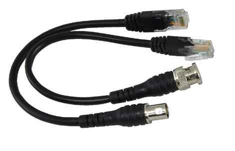
7 USB cable Remote Test BNC cable (with optional accessories) Remote Test Loopback test -5-


8 Multi-wire cable (with optional accessories) Loopback test Remote Test TEST RESULTS a. Continuity c. Short-circuit b. Open d. Miss-wired -6-


9 Cable Tracer Function rotary switch LED of signal strength ON/OFF button LINE1 LED Flashlight switch LINE2 LED Phone jack RJ11connector RJ45 connector Alligator clips Flashlight Figure1. Cable tracing Sensitivity control AMPLIFIER PROBE FEATURES The Amplifier Probe is designed to identify and trace wires or cables within a group without damaging the insulation. The flashlight function for easier cable tracing in the dark. An LED indication for the signal strength Works with any Tone Generator to identify wires. Volume control for increased sensitivity and adjustable to suit work environment. Recessed ON/OFF button prevents battery drain. Power supply is from any 9V battery with a life of approximately 100 hours. An audio jack is provided for headset. -7-
 In unterminated or non-working cables: Connect one test lead to an unterminated wire and the other test lead to another unterminated wire.")

10 INSTRUCTIONS Connecting the tone generator. In terminated working cables: Connect one test lead to a terminated wire and the other test lead to earth or equipment ground.(see Figure 1) In unterminated or non-working cables: Connect one test lead to an unterminated wire and the other test lead to another unterminated wire. MAINTENANCE The amplifier probe is maintenance free except for battery replacement. Remove the screw from the battery compartment, replace the 9V battery and reassemble. Warranty limited solely to repair or replacement; no warranty of merchantability, fitness for a particular purpose or consequential damages. TONE GENERATOR Function rotary switch Fast tone Slow tone Figure2 FEATURES Tone Generator is a great tool for locating and identifying cable pairs or individual conductors. Two bi-colored LEDs for Line1 and Line 2 indication of the polarities of the telephone lines. Identifying Tip and Ring of telephone lines. Identifying telephone line condition : Clear line, Busy line and Ringing line. -8-
 The unit has red and black alligator type terminals, a modular cable of 4 conductors with a strong connector. The continuity function only applies to Line1.")

11 It does not only serves as a tone generator, but it also serves as a continuity and polarity tester. Users can select a fast dual tone or a slow dual tone by the function rotary switch. (See Figure 2) The unit has red and black alligator type terminals, a modular cable of 4 conductors with a strong connector. The continuity function only applies to Line1. INSTRUCTIONS All of the following tests can be performed by using the red and black test leads or the modular plug. NOTE:When using the modular test plug, the polarity test function applies to Lines 1 and 2. The continuity function ONLY applies to Line 1. Figure3 POLARITY TEST: IDENTIFYING TIP & RING (SWITCH TO "POLARITY") 1. Connect the RED test lead to the side of one line and the BLACK lead to the side of another line. (See Figure 3) 2. The LED will glow "GREEN" when you connect the RED test lead to the RING SIDE of the line. 3. The LED will glow "RED" when you connect the RED test lead to the TIP SIDE of the line. -9-
12 IDENTIFYING LINE CONDITION (SWITCH TO "POLARITY") 1. Connect the RED test lead to the RING SIDE of the line and the BLACK to the TIP. (See Figure 3) 2. Watch the LED: 1.1 A BRIGHT "GREEN" LED indicates a CLEAR line. 1.2 A DIM "GREEN" LED indicates a BUSY line. 1.3 A BRIGHTLY FLICKERING "GREEN and RED" LED indicates a RINGING line. VERIFYING LINES (SWITCH TO "POLARITY" THEN "CONTINUITY") 1. Dial the line to be verified. 2. While the line is ringing, connect the RED lead to the RING SIDE of the line and the BLACK to the TIP. 3. In the "POLARITY" position, the indicator lamp will flicker "RED and GREEN" when the test leads are connected to the subject pair. 4. If you switch the test set to "CONTINUITY", it will terminate the call on the subject line. SENDING TONE (SWITCH TO "FAST TONE" or "SLOW TONE") CAUTION:DO NOT CONNECT TO ANY ACTIVE AC CIRCUIT EXCEEDING 24V IN THIS MODE. 1. Connect the test leads to the pair, or attach one lead to ground and one lead to either side of the line.(see Figure 1) 2. A fast dual alternating tone, or a slow dual alternating tone can be selected from the function rotaty switch. 3. Probe the suspected wires with the amplifier probe. Reception of tone will be strongest on the subject wire. In case of ready access to bare conductors, a handset or headphone may be used to receive the tone. TESTING CONTINUITY (SWITCH TO "CONTINUITY") CAUTION:DO NOT CONNECT TO ANY ACTIVE AC OR DC CIRCUIT IN THIS MODE. 1. Connect the test leads to the subject pair. 2. Switch to "CONTINUITY". 3. A bright "GREEN" light indicates continuity. The LED will not glow if the line resistance exceeds 12kΩ -10-
13 TESTING CONTINUITY BY USING TONE (SWITCH TO "FAST TONE" or "SLOW TONE") CAUTION:DO NOT CONNECT TO ANY ACTIVE AC OR DC CIRCUIT IN THIS MODE. 1. Connect the test leads to the subject pair. 2. Use a handset or headset at the remote end and touch the wire end(s) with the clip lead(s). 3. Reception of tone is an indication of continuity. MODULAR TESTING 1. All above tests are available through the modular plug for line 1 only - red and green wires. COAX TESTING 1. To test unterminated coax, connect red to outer shield and black to center conductor or red to outer shield and black to ground. 2. To test terminated coax, connect red to connector housing and black to center pin or red to connector housing and black to ground. -11-
14 Spicifications Master unit & Tone Generator Display Waveform Frequency Over Voltage Protection Single Tone Alternating Tone Connection LED Modules Bi-colored LEDs Square wave 1kHz±15% 80V DC Amplifier Probe & Receiving unit Frequency Detection Receiver Distance Sensitivity Control Flash light LED for signal strength LED module General Operating Temperature & Humidity Storage Temperature & Humidity Power Source Dimensions Weight Safety Standard Accessories Optional Accessories Fast and slow RJ11 connector and RJ45 connector 1Hz~12kHz <50cm V V V V 0 C~40 C, 80% Max -10 C~50 C, 80% Max Amplifier Probe & Receiving unit : 9V battery Master unit & Tone Generator : 9V battery Amplifier Probe & Receiving unit : 263(L) x 55(W) x 37.3(H)mm Master unit & Tone Generator : 180(L) x 82(W) x 43.8(H)mm Amplifier Probe & Receiving unit : 210g Master unit & Tone Generator : 280g EN EN EN EN Instruction manual Batteries Carrying case Self-test cable BNC testing cables Multi-wire testing cables -12-


15 Carrying case BNC testing cables (optional accessories) Multi-wire testing cables (optional accessories) -13-
Tone Generator and Probe
 Tone Generator and Probe JUNE 2001 TS141A-R2 CUSTOMER SUPPORT INFORMATION Order toll-free in the U.S. 24 hours, 7 A.M. Monday to midnight Friday: 877-877-BBOX FREE technical support, 24 hours a day, 7
Visit us at
 TM PRO3000 Toner and Probe Users Guide 99 Washington Street Melrose, MA 02176 Phone 781-665-1400 Toll Free 1-800-517-8431 Visit us at www.testequipmentdepot.com PN 2440799 (English) October 2005 2005 Fluke
Instruction Manual. 2in1 LAN Tester & Multimeter. Model: 57314
 Instruction Manual 2in1 LAN Tester & Multimeter Model: 57314 1 Contents Introduction... Features... Safety Precautions.. Meter Description... Electrical Specification... Operation.. AutoRanging Multimeter.
2 in1 LAN Tester & Multimeter. Model: PCE-LT 1
 www.pce-industrial-needs.com Tursdale Technical Services Ltd Unit N12B Tursdale Business Park Co. Durham DH6 5PG United Kingdom Phone: +44 ( 0 ) 191 377 3398 Fax: +44 ( 0 ) 191 377 3357 info@tursdaletechnicalservices.co.uk
200B-G Tone Probe. 200EP-G Tone Probe INSTRUCTION MANUAL. with Adjustable Volume
 INSTRUCTION MANUAL English...1 Français...9 Español...17 Deutsch...25 Italiano...33 Português do Brasil...41 200B-G Tone Probe with Adjustable Volume 200EP-G Tone Probe with Adjustable Volume, Visual Signal
Application of Cable Assembly
 Total Solution and Application of Cable Assembly ITEM Functions Txxpo Pxxxdxn FXXKE Pro skit MT-7068 Transmitter 1KHz 1KHz 1KHz 1KHz Tone Mode TWO (Hi/Lo) TWO (Hi/Lo) TWO (Hi/Lo) TWO (Hi/Lo) Compatible
All-in-one Toner a Probe Kit
 All-in-one Toner a Probe Kit User's Manual MT-7068 Maintenance Kit Congratulations on your purchase of MT-7068 Pro'sKit All-in-one Toner & Probe Kit. The Toner and Probe set is used to quickly trace and
T0046 PROFESSIONAL LAN CABLE TESTER USER GUIDE
 T0046 PROFESSIONAL LAN CABLE TESTER USER GUIDE INDEX 1. Interfaces and Controls...1 2. Power On...2 3. Setup...2 3.1 To set the UNIT...3 3.2 To set the LAN Length Adjustment...3 3.3 To set the COAX Length
TRIPLETT WireMaster Mapper
 TRIPLETT WireMaster Mapper 8-Way Wire & Cable Mapping Kit Instruction Manual 84-876 3/09 Test Equipment Depot - 800.517.8431 99 Washington Street, Melrose, MA 02176 TestEquipmentDepot.com TABLE OF CONTENTS
INSTALLATION SUPPLIES AND TOOLS
 Cable Identification, Locating, Testing Equipment 77 HP Tracer 2-Tone Generator Permits Fast, Accurate Wire Identification Provides Tone Signal, Continuity, Talk Battery, Line Condition Requires an Inductive
2 in 1 LAN Tester and Multimeter Model:
 2 in 1 LAN Tester and Multimeter Model: 72-8495 1 IMPORTANT SAFETY INFORMATION Please read these instructions carefully before use and retain for future reference. This instrument is designed and manufactured
Twisted Pair Cable Testers Int l Phone
 Twisted Pair Cable Testers Int l Phone 001.804.550.1121 Main LAN ProNavigator Tester & Remote If you re a technician on the go, you need the LAN ProNavigator from Paladin Tools! Two-piece tester includes
CM-220 True RMS AC CLAMP METER INSTRUCTION MANUAL
 CM-220 True RMS AC CLAMP METER INSTRUCTION MANUAL Safety International Safety Symbols This symbol, adjacent to another symbol or terminal, indicates the user must refer to the manual for further information.
ITC-3002-KIT TEST-ALL IV User Guide
 ITC-3002-KIT TEST-ALL IV User uide INDE I. ENERAL INFORMATION B. LED INDICATIONS C. PAIR SWITCHES D. FUNCTION SWITCH E. "A" LEAD CONTROL BUTTON F. BATTERY INDICATOR. BATTERY REPLACEMENT H. TEST-ALL IV
Hobbes LANtest Pro Remote Network Cable Tester
 1 (This manual covers the following models) User Manual 256652A 256652AT 256652A/IDT 256652A/TK 256652A/TFK LANtest Pro (previous 256652LB) LANtest Pro with tone generator LANtest Pro and 4 remote IDs
PS 150 SINGLE CHANNEL TELEPHONE INTERFACE. USER MANUAL August 2016
 PS 150 SINGLE CHANNEL TELEPHONE INTERFACE USER MANUAL August 2016 This product is designed and manufactured by: ASL Intercom B.V. Zonnebaan 42 3542 EG Utrecht The Netherlands Phone: +31 (0)30 2411901 Fax:
PS 230 DUAL CHANNEL REMOTE SPEAKER STATION. User Manual. January 2017 V1.0
 PS 230 DUAL CHANNEL REMOTE SPEAKER STATION User Manual January 2017 V1.0 Table of contents 1.0 GENERAL DESCRIPTION... 3 2.0 INSTALLATION... 4 3.0 FRONTPANEL CONTROLS & CONNECTORS... 4 4.0 SIDE PANEL CONNECTORS...
VOICE/DATA/VIDEO. Testers & Tools. 99 Washington Street Melrose, MA Phone Toll Free
 99 Washington Street Melrose, MA 02176 Phone 781-665-1400 Toll Free 1-800-517-8431 Visit us at www.testequipmentdepot.com VOICE/DATA/VIDEO Testers & Tools 2 CONNECTION 3 TESTING IDENTIFY VERIFY CRIMP TERMINATE
S-14 S-14. Compact Digital Multimeter. Compact Digital Multimeter
 S-14 Compact Digital Multimeter S-14 Compact Digital Multimeter SAFETY INFORMATION The following safety information must be observed to insure maximum personal safety during the operation at this meter
IDEAL INDUSTRIES, INC. TECHNICAL MANUAL MODEL:
 IDEAL INDUSTRIES, INC. TECHNICAL MANUAL MODEL: 61-796 The Service Information provides the following information: Precautions and safety information Specifications Performance test procedure Calibration
MS2115B Dual Display Digital Clamp Meter Operation Manual ZERO MIN RANGE HOLD
 MS2115B Dual Display Digital Clamp Meter Operation Manual REL MAX B.L ZERO MIN RANGE HOLD B CONTENTS 1. Safety Information...1 1.1 Preparation...1 1.2 Usage...2 1.3 Mark...3 1.4 Maintenance...4 2. Description...4
Radio Shack Telephone Tester ( )
") Radio Shack Telephone Tester (430-0114) Telephone Tester (430-0114) Features Faxback Doc. # 15708 The Radio Shack Telephone Tester represents a multi-function, value featured advance in telephone service
Radio Shack Telephone Tester (430-0114) Telephone Tester (430-0114) Features Faxback Doc. # 15708 The Radio Shack Telephone Tester represents a multi-function, value featured advance in telephone service
Model INSTRUCTION MANUAL DIGITAL MULTIMETER
 Model 57040 INSTRUCTION MANUAL DIGITAL MULTIMETER SAFETY INFORMATION This multimeter has been designed according to IEC 1010 concerning electronic measuring instruments with an overvoltage category (CAT
HOUSING DEVICES, INC. HDI ADA - ARCU. Installation & Operations Manual. Made in the USA
 HOUSING DEVICES, INC. ADA - ARCU Installation & Operations Manual Made in the USA ADA - ARCU 5 & 10 Pre-Installation Requirements: For each ADA-1000 in the elevator you must run a twisted, shielded, 22
Model: Pro93 TRUE RMS LEAKAGE CURRENT TESTER
 Model: Pro93 TRUE RMS LEAKAGE CURRENT TESTER CONTENTS TITLE PAGE I. Safety Information.......1 Environmental Conditions... 1 Explanation of Symbols..... 1 II. Specification..... 2 General Specification...
MEASURING AND TESTING INSTRUMENTS
 MEASURING AND TESTING INSTRUMENTS Whether measuring temperature, current or voltage testing the right measuring tool can facilitate the everyday work. If one wants to perform several measuring tasks at
User s Guide. 600A True RMS AC/DC Clamp Meter. Model 38389
 User s Guide 600A True RMS AC/DC Clamp Meter Model 38389 Safety International Safety Symbols This symbol, adjacent to another symbol or terminal, indicates the user must refer to the manual for further
JANUARY 2000 TS800A TS801. MicroScanner
 JANUARY 2000 TS800A TS801 MicroScanner CUSTOMER SUPPORT INFORMATION Order toll-free in the U.S.: Call 877-877-BBOX (outside U.S. call 724-746-5500) FREE technical support 24 hours a day, 7 days a week:
PS 430 FOUR CHANNEL REMOTE SPEAKER STATION. User Manual. January 2017 V1.0
 PS 430 FOUR CHANNEL REMOTE SPEAKER STATION User Manual January 2017 V1.0 Table of contents 1.0 GENERAL DESCRIPTION... 3 2.0 INSTALLATION... 4 3.0 FRONTPANEL CONTROLS & CONNECTORS... 4 4.0 SIDE PANEL CONNECTORS...
MTP INSTRUCTION MANUAL
 DT-118B MTP INSTRUCTION MANUAL Pocket Autoranging Digital Multimeter 3 in 1 Model MTP-1025 Auto Ran ging DMM Hz% A OFF V AU TO PO WER OFF MTP Instruments Table of Contents Introduction Page 1 Features
DM-918 OPERATIONS MANUAL AUTORANGING MULTIMETER
 DM-918 OPERATIONS MANUAL AUTORANGING MULTIMETER SAFETY INFORMATION The following safety information must be observed to ensure maximum personal safety during the operation of this meter: This meter is
HUAWEI FT2260 Home Phone Connect Quick Start
 HUAWEI FT2260 Home Phone Connect Quick Start Introduction Top View The figures are only for your reference, the actual shape and color of the product may differ slightly. 7 8 9 10 1 2 3 4 5 6 1 Power on/off
MT-7071 LCD Cable Length Toner & Probe Kit Getting Started Guide
 LCD Cable Length Toner & Probe Kit Getting Started Guide INSTRUCTION Transmitter/Remote Unit: 1. RJ45 (8 pin) connectors: Used for cable mapping and verifying cable status of RJ45 (8 pin) LAN cable with
Model P4017 Single Channel USB Oscilloscope. Quick Start Guide
 Model P4017 Single Channel USB Oscilloscope Quick Start Guide General Warranty BNC warrants that the product will be free from defects in materials and workmanship for 3 years from the date of purchase
OPERATOR S INSTRUCTION MANUAL DIGITAL MULTIMETER
 OPERATOR S INSTRUCTION MANUAL DIGITAL MULTIMETER SAFETY INFORMATION This multimeter has been designed according to IEC 1010 concerning electronic measuring instruments with an overvoltage category (CATⅡ)
BENCH-TOP DIGITAL MULTIMETER INSTRUCTION MANUAL
 BENCH-TOP DIGITAL MULTIMETER INSTRUCTION MANUAL SK-4033 / SK-4035 Thank you for purchasing KAISE MODEL SK-4033/4035 BENCH-TOP DIGITAL MULTIMETERS. To obtain the maximum performance of this instrument,
BUTT SET MODEL TT-200
 TT-200 (BS-100) 2/12/01 4:00 PM Page 1 BUTT SET MODEL TT-200 Instruction Manual Copyright 2001 Amprobe AMPROBE TT-200 (BS-100) 2/12/01 4:00 PM Page 2 INTRODUCTION The TT-200 is designed for the installers,
User's Manual. Autoranging Datalogging Insulation Tester (Megohmmeter) with PC Interface. Model
 with PC Interface. Model") User's Manual Autoranging Datalogging Insulation Tester (Megohmmeter) with PC Interface Model 380366 Introduction Congratulations on your purchase of the Extech 380366 Datalogging Insulation Tester. The
User's Manual Autoranging Datalogging Insulation Tester (Megohmmeter) with PC Interface Model 380366 Introduction Congratulations on your purchase of the Extech 380366 Datalogging Insulation Tester. The
TT-SI 50 50MHz DIFFERENTIAL PROBE USER S MANUAL
 TT-SI 50 50MHz DIFFERENTIAL PROBE USER S MANUAL This probe is in compliance with IEC-1010.1, IEC-1010.2-031 CAT I or CAT II, Pollution Degree 2. 1. Safety Terms and Symbols Terms appear in this manual:
User's Guide. MiniTec TM Series Model MN25 MultiMeter
 User's Guide MiniTec TM Series Model MN25 MultiMeter Warranty EXTECH INSTRUMENTS CORPORATION warrants this instrument to be free of defects in parts and workmanship for one year from date of shipment (a
Operation Connection: See Figure 1 Keypad: Figure 2
 PN: 84-902 1/13 Overview The Triplett TeleTalker 330 is a rugged and durable professional Telephone Test Set providing all of the basic features necessary to test and maintain analog telephone installations.
What can the DD700 Do
 What can the DD700 Do RF signal detector for 100HZ to 3.5 GHz - Wireless CCTV (hidden camera) - Wireless Phone line tap detection - Laser taps detection and Laser tapping prevention using white noise generator.
BT603 Cable Dr. - All-in-One LAN Network Verifier with TDR/TDX Length Measurement and Network Performance Test
 BT0 Cable Dr. - All-in-One LAN Network Verifier with TDR/TDX Length and Network Performance Test Cable Dr. (Model No.: BT0) is the all-in-one and easy-to-use network qualification unit measuring logical
SuperBus 2000 Phone Interface/Voice Module Installation Instructions
 SuperBus 2000 Module Installation Instructions Product summary The SuperBus 2000 (PIV) Module provides phone and voice functions for the Concord, Concord 4, and Concord Express (v4) panels. The PIV module
EARTH RESISTANCE & RESISTIVITY TESTER
 99 Washington Street Melrose, MA 02176 Phone 781-665-1400 Toll Free 1-800-517-8431 Visit us at www.testequipmentdepot.com BST-ET103 EARTH RESISTANCE & RESISTIVITY TESTER INSTRUCTION MANUAL INDEX 1. INTRODUCTION...
Mini Digital Multimeter
 User's Guide Mini Digital Multimeter Model MN15 99 Washington Street Melrose, MA 02176 Phone 781-665-1400 Toll Free 1-800-517-8431 Visit us at www.testequipmentdepot.com Back to the Extech MN15/MN16 Series
MD9 MULTIDROP INTERFACE INSTRUCTION MANUAL
 MD9 MULTIDROP INTERFACE INSTRUCTION MANUAL REVISION: 01/05/03 COPYRIGHT (c) 1987-2003 CAMPBELL SCIENTIFIC, INC. This is a blank page. WARRANTY AND ASSISTANCE The MD9 MULTIDROP INTERFACE is warranted by
POCKET MULTIMETER Model No: MM18
 INSTRUCTIONS FOR: POCKET MULTIMETER Model No: MM18 Thank you for purchasing a Sealey product. Manufactured to a high standard this product will, if used according to these instructions and properly maintained,
Net-Ritef Continuity and Wiremap Tester Trace-Ritef Tone Generator and Amplified Tone Tracer User's Guide.
 Net-Ritef Continuity and Wiremap Tester Trace-Ritef Tone Generator and Amplified Tone Tracer User's Guide www.jdsu.com/know Voltage Probe Tracer/Power Button Volume Up/Down Indicator LED Power/Tone Type
Autoranging True RMS Multimeter User Manual
 Autoranging True RMS Multimeter User Manual Please read this manual before switching the unit on. Important safety information inside. Contents Page 1. Safety Information... 4 2. Safety Symbols... 5 3.
Product Manual. Surge Protected Metal 7- Port USB 2.0 Hub DIN RAIL Mount Kit NEC Chip
 Surge Protected Metal 7- Port USB 2.0 Hub DIN RAIL Mount Kit NEC Chip Product Manual Coolgear, Inc. Version 1.1 September 2017 Model Number: USBG-7DU2i 2 USBG-7DU2i Product Manual Revision History Revision
BS 15 BASIC SERIES USER MANUAL FOR THE SINGLE CHANNEL BELTPACK CONTENTS
 BASIC SERIES USER MANUAL FOR THE BS 15 SINGLE CHANNEL BELTPACK CONTENTS 1.0 GENERAL DESCRIPTION... 3 2.0 UNPACKING... 3 3.0 INSTALLATION... 3 4.0 FRONT PANEL CONTROLS... 4 5.0 REAR PANEL CONNECTORS...
USER'S MANUAL DCL-650
 USER'S MANUAL Clamp on Multimeter - Compact Design True RMS AC/DC DCL-650 CIRCUIT-TEST ELECTRONICS www.circuittest.com Safety International Safety Symbols This symbol, adjacent to another symbol or terminal,
User's Guide. Phase Sequence and Motor Rotation Tester Model
 User's Guide Phase Sequence and Motor Rotation Tester Model 480403 Introduction Congratulations on your purchase of the Extech Model 408403 Motor and Phase Rotation Indicator. This handheld instrument
AC/DC TRUE RMS CLAMP METER ACM-2036
 AC/DC TRUE RMS CLAMP METER ACM-2036 User s Manual Safety International Safety Symbols This symbol, adjacent to another symbol or terminal, indicates the user must refer to the manual for further information.
Mini Digital Multimeter
 User's Guide Mini Digital Multimeter Model MN15 Introduction Congratulations on your purchase of the Extech MN15 MultiMeter. The MN15 offers AC/DC Voltage, AC/DC Current, Resistance, Diode, and Continuity
16 Port USB 3.0 Metal Hub w/surge Protection Rack/DIN-RAIL Mountable Coolgear, Inc. Version 1.1 September 2017 Model Number:
 16 Port USB 3.0 Metal Hub w/surge Protection Rack/DIN-RAIL Mountable Product Manual Coolgear, Inc. Version 1.1 September 2017 Model Number: USB3-16U1 2 USB3-16U1 Product Manual Revision History Revision
Fluke 43B. Power Quality Analyzer. Getting Started. EN June Fluke Corporation, All rights reserved. Printed in The Netherlands.
 Power Quality Analyzer EN June 2005 2001-2005 Fluke Corporation, All rights reserved. Printed in The Netherlands. All product names are trademarks of their respective companies. PLACING ORDERS AND GETTING
Talk-N-Tracef Communication and Tracing Set. User's Guide.
 Talk-N-Tracef Communication and Tracing Set User's Guide www.jdsu.com/know ON / RING BUTTON When unit is off, pressing this button turns on power to talk circuitry. When unit on, pressing this button
Mini Digital Multimeter
 User Manual Mini Digital Multimeter Model MN15A Additional User Manual Translations available at www.extech.com Introduction Congratulations on your purchase of the Extech MN15A MultiMeter. The MN15A offers
Autoranging Multimeter plus IR Thermometer Extech 450 Patented
 User's Guide Autoranging Multimeter plus IR Thermometer Extech 450 Patented Introduction Congratulations on your purchase of the Extech 450 (part number EX450) Autoranging Multimeter plus IR Thermometer.
OPERATING INSTRUCTION. Pen-Type Digital Multimeter
 OPERATING INSTRUCTION Pen-Type Digital Multimeter International Safety Symbols This symbol, adjacent to another symbol or terminal, indicates the user must refer to the manual for further information.
NX8 Pocket Toner Users Guide
 NX8 Pocket Toner Users Guide The NX8 Pocket Toner lets you quickly do tests for continuity, short circuits, ac and dc voltage, and 50 Ω or 75 Ω termination. The standard adapters let you use the toner
Model A Mini AC/DC Clamp Meter. User's Guide
 Model 380950 80A Mini AC/DC Clamp Meter User's Guide Introduction Congratulations on your purchase of the Extech 80A Mini AC/DC Clamp Meter. The Model 380950 measures AC/DC Current, AC/DC Voltage, Resistance,
4 Channel DMX Driver Instruction Manual
 LEDstuff.co.nz 4 Channel DMX Driver Instruction Manual Quality LED Lighting Products The LEDstuff 4 Channel DMX Driver is a flexible module that is an ideal addition to an existing home automation or lighting
Modem Installation and Networking Instructions
 Modem Installation and Networking Instructions P/N 36870 Rev F Introduction The following instructions cover connecting a phone line to an incoming phone source, installing a modem, and setting up a network
TETRIS 2500 High Impedance Active Probe. Instruction Manual
 TETRIS 2500 High Impedance Active Probe Instruction Manual Copyright 2018 PMK GmbH All rights reserved. Information in this publication supersedes that in all previously published material. Specifications
Secured Series: Hub Plus Kit Single Door Controller Package Installation Manual
 Secured Series: Hub Plus Kit Single Door Controller Package Installation Manual This package is designed to simplify the connections to our Secured Series Hub Plus Controller. This will translate into
SERVICE MANUAL MODEL SSW-520-F
 SSW-520-F-ISSUE4.0 SERVICE MANUAL FOR MODEL SSW-520-F HANDS FREE STAINLESS STEEL TELEPHONE EQUIPPED WITH LOW POWER SPEAKER BOARD Serving the Telephone Industry Since 1930 Communication Equipment 519 West
User's Guide. Digital Multimeter. Model MN42
 User's Guide Digital Multimeter Model MN42 Introduction Congratulations on your purchase of the Extech MN42 MultiMeter. The MN42 offers AC/DC Voltage, DC Current, and Resistance testing. Proper use and
OPERATION MANUAL. separate probe, RS-232 SOUND LEVEL METER. Model : SL-4013
 separate probe, RS-232 SOUND LEVEL METER Model : SL-4013 Your purchase of this SOUND LEVEL METER marks a step forward for you into the field of precision measurement. Although this SOUND LEVEL METER is
Digital Clamp Meter User Manual
 Compact AC, AC/DC Digital Clamp Meter User Manual Please read this manual before switching the unit on. Important safety information inside. Contents 1.Safety... 3 2.Safety Notes... 3 3.Warnings... 3 4.Cautions...
DPA 7000 PATENTS PENDING TELEPHONE AND LINE ANALYZER
 TM TELEPHONE AND LINE ANALYZER DPA 7000 PATENTS PENDING TELEPHONE AND LINE ANALYZER PATENTS PENDING The TALAN represents state-of-the-art capability to rapidly and reliably detect and locate illicit tampering
OPERATOR S MANUAL MODEL LS110 MINI-PBX SIMULATOR
 1 OPERATOR S MANUAL MODEL LS110 MINI-PBX SIMULATOR Micro Seven, Inc. 1095-K N.E. 25 th Hillsboro, OR 97124 U.S.A. phone: 503-693-6982 fax: 503-693-9742, email to: sales@microseveninc.com www.microseveninc.com
User's Guide. Extech AM A AC Analog Clamp Meter
 User's Guide Extech AM300 300A AC Analog Clamp Meter Introduction Congratulations on your purchase of the Extech AM300 Analog Clamp Meter. This device measure AC Voltage and Current, DC Voltage, and Resistance.
 DESCRIPTION ------------------------------------------------------------------------------------------------------------------------------------- The HEB Series camera is an internet protocol based megapixel
OPERATING INSTRUCTION
 OPERATING INSTRUCTION AUTORANGING MULTIMETER MAX Ω F C 10A MAX every 15 min. COM V SAFETY INFORMATION The following safety information must be observed to insure maximum personal safety during the operation
SERVICE MANUAL MODEL SSW-521-D2-ADA
 SSW-521-D2-ADA-SPK1.07UNVLr3-ADA-ISSUE4.0 SERVICE MANUAL FOR MODEL SSW-521-D2-ADA STAINLESS STEEL HANDS FREE WALL TELEPHONE WITH OPTIONAL ADA FEATURE AND OPTIONAL SECOND-NUMBER AUTO-DIAL FEATURE EQUIPPED
R5050. Model. Instruction Manual. TRMS AC/DC Clamp Meter. reedinstruments. www. com
 Model R5050 TRMS AC/DC Clamp Meter Instruction Manual reedinstruments com Table of Contents Safety... 3 Features... 4 Specifications...4-6 Instrument Description...7-8 Measurement Procedures...9-12 Battery
IT100. Users Manual. IntelliTone Pro Toner and Probe
 IT100 IntelliTone Pro Toner and Probe Users Manual March 2006 2006 Fluke Corporation. All rights reserved. All product names are trademarks of their respective companies. LIMITED WARRANTY AND LIMITATION
User Manual. 400Amp AC Clamp Meter + NCV. Model MA430. Additional User Manual Translations available at
 User Manual 400Amp AC Clamp Meter + NCV Model MA430 Additional User Manual Translations available at www.extech.com Introduction Congratulations on your purchase of this Extech MA430 Clamp Meter. This
IDEAL INDUSTRIES INC. TECHNICAL MANUAL MODEL:
 IDEAL INDUSTRIES INC. TECHNICAL MANUAL MODEL: 61-795 The Service Information provides the following: Precautions and safety information Specifications Performance test procedure Calibration and calibration
TELEPHONE AND LINE ANALYZER
 The TALAN represents state-of-the-art capability to rapidly and reliably detect and locate illicit tampering and security vulnerabilities on both digital and analog telephone systems. Marketing Characteristics
Wireless Key fob, Key pad & Receiver Range
 Wireless Key fob, Key pad & Receiver Range 4Ch Wireless Receiver 4x Voltage Free relay outputs (NO + NC) 100m Transmission range Multiple user codes 2 Channel wireless control Clear hinge up lid 12V DC
User's Guide. 800 Amp Clamp Meters. EX710 AC Clamp meter EX720 True RMS AC Clamp meter EX730 AC/DC True RMS Clamp meter
 User's Guide 800 Amp Clamp Meters EX710 AC Clamp meter EX720 True RMS AC Clamp meter EX730 AC/DC True RMS Clamp meter Introduction Congratulations on your purchase of the EX710, EX720, or EX730 Clamp DMM.
User s Guide. RP7000S Series Single-Ended Active Probe. Nov RIGOL Technologies, Inc.
 User s Guide RP7000S Series Single-Ended Active Probe Nov. 2013 RIGOL Technologies, Inc. Guaranty and Declaration Copyright 2013 RIGOL Technologies, Inc. All Rights Reserved. Trademark Information RIGOL
DTMF Device/ Relay Remote Controller
 DTMF Device/ Relay Remote Controller This high quality board is designed to get DTMF input from Internet / Mobile / Wireless receivers/ Computer for operation of 4 relays. AC 250 V AC rated Relays can
USER MANUAL. Mini Multimeter with Non-Contact Voltage Detector (NCV) Model EX310
 Model EX310") USER MANUAL Mini Multimeter with Non-Contact Voltage Detector (NCV) Model EX310 Introduction Congratulations on your purchase of the Extech EX310 MultiMeter. The EX310 offers AC/DC Voltage, AC/DC Current,
USER MANUAL Mini Multimeter with Non-Contact Voltage Detector (NCV) Model EX310 Introduction Congratulations on your purchase of the Extech EX310 MultiMeter. The EX310 offers AC/DC Voltage, AC/DC Current,
HG-21B. Digital Over-Ear Headphones. User Manual
 HG-21B Digital Over-Ear Headphones User Manual Congratulations! Thank you for choosing AudioMX HG-21B Digital Over- Ear Headphones. To get familiar with this product, please read this manual carefully
Kramer Electronics, Ltd. USER MANUAL. Model: WP-101. XGA/Stereo Audio Line Driver
 Kramer Electronics, Ltd. USER MANUAL Model: WP-101 XGA/Stereo Audio Line Driver Contents Contents 1 Introduction 1 2 Getting Started 1 3 Overview 1 3.1 Defining the EDID 2 3.2 Recommendations for Achieving
User's Guide. True RMS Multimeter plus IR Thermometer. Extech 470 Patent Pending
 User's Guide True RMS Multimeter plus IR Thermometer Extech 470 Patent Pending Introduction Congratulations on your purchase of the Extech 470 (part number EX470) True RMS Autoranging Multimeter plus IR
ETHOS Auto Ranging Digital Multimeter
 ETHOS 5020 Auto Ranging Digital Multimeter 1 1. SAFETY INFORMATION SAFETY SYMBOLS Warning! Dangerous Voltage (Risk of electric shock). Caution! Refer to the user s manual before using this Meter. Double
SERVICE MANUAL MODEL SSP-363-E (FORMERLY SSP-365-E)
") SSP-363-E-(SSP-365-E)-ADT1.03-ISSUE4.0 SERVICE MANUAL FOR MODEL SSP-363-E (FORMERLY SSP-365-E) STAINLESS STEEL PANEL TELEPHONE WITH 12 BUTTON AUTOMATIC DIALER EQUIPPED WITH ADT1.03 FIRMWARE Serving the
SSP-363-E-(SSP-365-E)-ADT1.03-ISSUE4.0 SERVICE MANUAL FOR MODEL SSP-363-E (FORMERLY SSP-365-E) STAINLESS STEEL PANEL TELEPHONE WITH 12 BUTTON AUTOMATIC DIALER EQUIPPED WITH ADT1.03 FIRMWARE Serving the
Test devices and Multifunction timer relay
 Test devices and Multifunction timer relay VARIOTEST ROTATEST CSG420 Test devices Industries VARIOTEST The Condor-VARIOTEST is a universal test instrument featuring acoustic signals for: P. 145 Testing
OPERATING INSTRUCTIONS PA AMPLIFIER P-1812
 OPERATING INSTRUCTIONS PA AMPLIFIER P-1812 Please follow the instructions in this manual to obtain the optimum results from this unit. We also recommend that you keep this manual handy for future reference.
Operating Instructions PRO-AB /6.15. Leakage Current Measuring Adapter
 Operating Instructions PRO-AB Leakage Current Measuring Adapter 3-349-621-15 3/6.15 Table of Contents Page 1 Scope of delivery...2 2 Safety Precautions...2 3 General...3 4 Preparing for Measurement...4
Connecting the THP-700RTS to a Telephone and Radio Console - Summary. DynaMetric. Made in USA THP-700RTS
 Connecting the to a Telephone and Radio Console - Summary RECORDER 700RTS 700RTS PHONE PIN HEADSET PIN JACK PIN PLUG* PIN JACK 1 1 MIC 1 1 Make same 2 2 EAR 2 2 as Phone 3 3 EAR 3 3 Jack 4 4 MIC 4 4 PIN
INSTALLATION INSTRUCTIONS
 INSTALLATION INSTRUCTIONS MicroComm DXI. Intent & Scope This document describes the installation procedure for the IMS-30 Intercom Master Station and the MAI-420 or MAI-20 Master Audio Interface. The earliest
700 Series 200 Amp Clamp Meters
 700 Series 200 Amp Clamp Meters #61-700 #61-701 #61-702 1 2 3 6 5 7 4 8 1. Non-contact voltage (NCV) (#61-701 and #61-702) With the NCV tab on the tip of the clamp close to an AC voltage, press the NCV
PS 630 SIX CHANNEL REMOTE SPEAKER STATION. User Manual. January 2017 V1.0
 PS 630 SIX CHANNEL REMOTE SPEAKER STATION User Manual January 2017 V1.0 Table of contents 1.0 GENERAL DESCRIPTION... 3 2.0 INSTALLATION... 4 3.0 FRONTPANEL CONTROLS & CONNECTORS... 4 4.0 REAR PANEL CONNECTORS...