Assembly Instructions for the KA Electronics IGFO Input Gain Filter Output Board
|
|
|
- Tobias Wilson
- 5 years ago
- Views:
Transcription

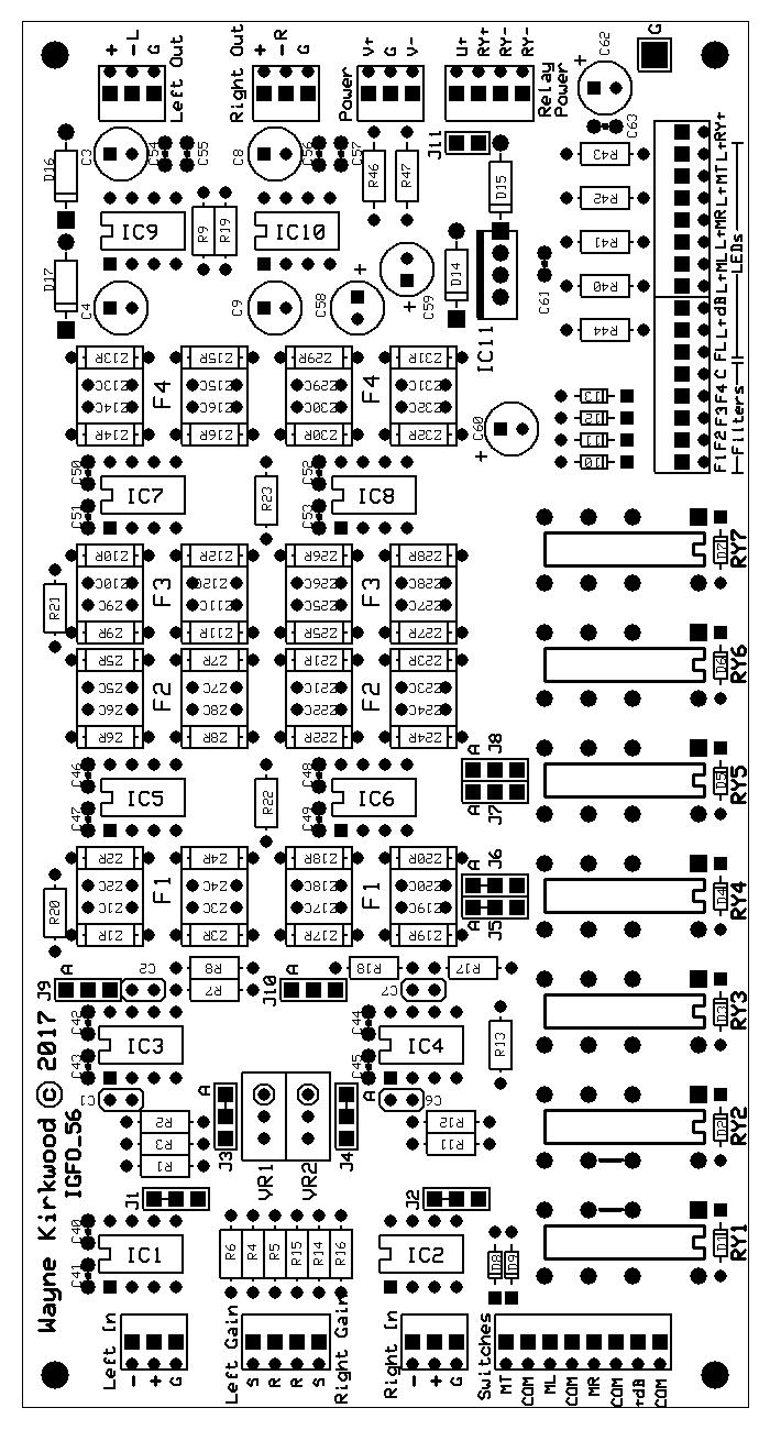
1 Assembly Instructions for the KA Electronics IGFO Input Gain Filter Output Board IGFO PC Board Stuffing Guide Install IC sockets Place the PC Board on the work bench silkscreen side face up. Place ten 8 pin IC sockets into their respective locations. Observe orientation of the notch. Make sure that you do not place the sockets in the bypass capacitor holes. Tip: Lift the board up and place a piece of cardboard on top of the board to form a sandwich of PC board, sockets and cardboard. The cardboard is used to hold the sockets in place so the board can be turned over without the sockets dropping out. Flip the board over. Tack Solder only two of the corner IC pins. Put downward pressure on the PC board to make certain the sockets are seated on the board as you solder. Once all the IC sockets are tack soldered, flip the board over. Make certain that each socket is correctly oriented, fully seated on the board and square. If you're satisfied with the placement of the sockets, solder all of the remaining pins. Do not overfill the connection with solder because it can run underneath the socket and form a short between pins. Visually check each pin's connection particularly those to the ground plane.
2 Reheat any pins if needed. Do not trim the IC socket leads. Install resistors and diodes Install eight 7K5Ω 1% resistors at R1, R4, R7, R8, R11, R14, R17 and R18. Install two 9K09Ω 1% resistors at R2 and R12. Install two 562Ω 1% resistors at R3 and R13. Install two 3K74Ω 1% resistors at R5 and R15. Install four 49R9Ω 1% resistors at R6, R9, R16 and R19. Install four 10KΩ 1% resistors at R20-R23. Note: If you already know what switch and LED you are using check to see what LED current looks best. The following instructions assume 5 ma current. Install optional LED current limiting resistors R40 R44. If 12V relays are used, install five 2KΩ 1/4W for an LED current of approximately 5 ma. If 24 relays are used install 4K99 1/4W. Install two 1R 1W fusible resistors at R46 and R47. Install the Filter Frequency-setting Resistors The MTC-IGFO board offers four stereo pairs of filter frequencies which can be a combination of high-pass and low-pass responses. Two MTC-IGFO boards can be cascaded to have eight stereo pairs of filters. A single MTC-IGFO board is usually configured with two high-pass and two lowpass filters. Two cascaded MTC-IGFO boards are usually configured as four high-pass and four low-pass. Cascaded MTC-IGFO boards can be assembled which have only the input or output circuitry needed for that board or they can be built with identical input/output circuitry to provide an optional balanced insert point between filter groups. The filters are configured for high or low-pass response by the placement of the tuning resistors and capacitors. The filter frequencies are set by the value of the resistors. The PC board component designation for the filter resistors and capacitors are labeled Z rather than the conventional R or C. Resistors R24-R39 set the filter frequencies. The tuning capacitors will be installed in a later step. For most filters and the examples shown use the standard values of 0.33 µf for the high-pass sections (two per filter) and 1000pF/470pF (one each) for the low-pass sections. In the Appendix there are example instructions for a single MTC-IGFO with 20
3 and 30 Hz high-pass and 22 and 27 khz low-pass responses. Note: This document generally describes a single board built with two highpass and two low-pass filters. An example of two cascaded MTC-IGFO for vinyl mastering is also shown having values of 20/30/40/50 Hz high-pass and 12/14/16/18 khz low-pass. The schematics also contain links to an online calculator for custom filter frequencies. Please refer to the Appendix and schematic pages 4 and 5 to install resistors R24-R39 and the capacitors. Install R24-R39 and then return to the following step. Install diodes Install thirteen 1N4148 diodes at D1-D13. Observe polarity. Install four 1N4004 diodes at D14-D17. Observe polarity. Install ceramic capacitors Install twenty 100 nf (0.1uF) at C40-C57, C61 and C63. *Note: On two board cascaded IGFO systems the values of C1 and C6 are different. Install 100 pf for the first board and 22 pf for C1 and C6 on the second. Install two 100 pf at C1 and C6. (22 pf on board #2.) Install two 22 pf at C2 and C7. Install jumper headers Install the jumper shunts onto the header pins before you solder them. (The shunts serve as insulators that allow you to position them while soldering without burning your fingers.) You will need eleven shunts. The shunts are positioned during installation in the locations that will be used in final test. The shunts should be installed with small openings on the bottom. Some shunts also have openings on the sides to retain the internal pins. When shunts are installed side-by-side, make sure the openings are not both on the inside to prevent shorting between shunts. When installing the headers, tack solder only one pin and reheat it to adjust the position of the header so that its square and flush with the board. Once you're satisfied with the orientation of the headers solder the remaining pins. Install six 3 pin headers at J1-J4, J9 and J10. The shunts on J1-J2 should be in the top A position. Shunts on J3-J4 should be in the left-hand B position.
4 Temporarily put shunts on J9 and J10 in either position. J9 and J10's shunts are used only for special configurations. After soldering, remove J9 and J10s shunts and store them on the top pins so they do not connect to the middle pin. Install two 6 pin headers at J5/J6 and J7/J8. When installing shunts on J5-J8 make certain that openings on the sides of the shunts point outwards. Otherwise the left and right channels may touch and short together. Install J5/J6's shunts vertically on the top two pins. (Position A) Install J7/J8's shunts vertically on the bottom two pins. (Position B) Install one 2 pin header with shunt at J11. Install Phoenix connectors When installing the Phoenix connectors make sure the openings for the wires point outward to the edge of the board. When installing the connectors, tack solder only one pin and reheat it to adjust the position of the connector so that its square and flush with the board. Once you're satisfied with the orientation of the connector, solder the remaining pins. Install five 3 pin Phoenix connectors at the Left In, Right In, Left Out, Right Out and Audio Power connector locations. Note: External gain connections are usually not installed on the second cascaded filter board. Installation of the Phoenix Gain connector is optional on those boards. Install two 4 pin Phoenix connectors at the Gain and Relay Power connector locations. Install three 8 pin Phoenix connectors at the Switches and LED/Relay Power locations. Install electrolytic capacitors Note: The + terminals for the electrolytic capacitors have a square pad. Where space permits there is also a + silkscreen marking. The longer capacitor lead is the positive lead. Bipolar capacitors, which do not have a polarity, will be installed in four locations. Make certain that you have the right type of capacitor before soldering it. Install four 10uF 35V (or 50V) bipolar electrolytic capacitors at C3, C4, C8 and C9. Install two 47uF 35V polarized electrolytic capacitors at C58 and C59. The polarity of these capacitors are critical. Install two 10uF 50V polarized electrolytic capacitors at C60 and C62. The polarity of these capacitors are critical. Install film capacitors Sixteen film capacitors, C20-C35, set the filter frequencies. Please refer to
5 schematic sheets 4 and 5 for the values and the Appendix for the installation locations to be used in your particular configuration. High pass filter capacitors are usually 0.33 µf. Low pass film capacitors are 1000 pf and 470 pf. Install C20-C35 according to the Appendix and then return here. Install the relays The IGFO can be built as either an input with gain trim or cascaded filter board. The number of relays installed depends on the configuration. In most cases seven relays are installed on the input board and four relays are installed on cascaded filter boards. The relay coils can be either 12 or 24V DC. The Mouser BOM specifies 12V coils. An optional 7812 regulator can be installed, in a later step, at IC11 for use with 24V supplies. Tip: When installing the relays place all of them on the circuit board and align them. When you're satisfied with the alignment place a strip of adhesive masking tape across the tops of all of them. This allows the relays to be soldered as a unit. Solder the corner pins making sure that each relay is flush with the PC board. Remove the masking tape. If the alignment is correct and the relays are flush with the board solder the remaining pins. For an input board install seven relays at RY1-RY7. For a cascaded filter board, without mute and +5dB gain, install three relays at RY4-RY7. Install trim pots IGFO boards with input gain trim require calibration of the -5.5 db step and installation of VR1 and VR2. Install 500Ω trim pots at VR1 and VR2 with the screw adjustment on the righthand side. Install optional relay voltage regulator If 12V relays are used in a 24V system an LM7812 regulator may be installed at IC11. Mount a small TO-220 heat sink onto the LM7812 before installing it with a 1/ screw, #4 fiber washer and 4-40 nut. Thermal grease is not required. Insert the LM7812 and heat sink assembly onto the circuit board making sure that the lower edge of the regulator's leads, where they widen, are flush with the board. The bottom of the heat sink should clear the top of the PC board by about 0.1 and may contact the body of D15. Solder only the center pin of IC11 making certain that the regulator is mounted square. If you are satisfied with the orientation of the regulator solder the remaining pins. If it is not square re-heat the pin and adjust it. J11 must be linked for the regulator to supply power to the relay coils. If
6 an external 12V relay supply is used and the on-board regulator is not needed open J11. Note: Do not install the ICs at this time. Check all solder connections and reheat or re-flow them if necessary. When component leads are trimmed after soldering the solder joint becomes fractured. It is always a good idea to re-flow all solder connections after lead trimming while checking for bridges or pins which may have missed being soldered. If you add solder during this step do so sparingly particularly under IC sockets. Solder can flow through the PC board vias to the underside of the IC socket and cause shorts between pins. If you prefer to remove the solder flux residue from the PC board now is a very good time to do it. When you're finished cleaning inspect every joint under magnification. Install spacers Install four 4-40 threaded hex spacers at the board mounting holes. Place the four fiber washers between the PC board and the hex spacer and secure using four /4 screws. Four additional screws and fiber washers are in the bill-of-materials for securing the PC board to the chassis. Initial Tests The board should be tested on a power supply before installing the ICs. Initial DC Tests Connect a source of bipolar DC power. If a variable power supply is used, slowly raise the voltage to about +/-15V. There should be no measurable current draw. If excess current is drawn check the board for solder bridges and correct polarity of D13, D14 and all the electrolytic capacitors. Check the voltages at pin 7 of IC1 and IC2. It should be +15V. The voltages at pin 4 should be -15V. Check the voltage at pin 8 of IC3-IC8. It should be +15V. The voltages at pin 4 should be -15V. Check the voltage at pin 6 of IC9 and IC10. It should be +15V. The voltages at pin 5 should be -15V. Check the relay power supply if it is installed. Connect the +15V supply to Phoenix connector terminal U+. Connect the -15V supply to Phoenix terminal RY-. J8 should be linked. Measure the voltage between RY- and RY+. It should measure approximately 12V or 24V depending on the voltage regulator installed. If any of the voltages are out of range look for solder bridges or an unsoldered pin or component lead.
7 Remove power. Install the ICS Install two THAT1246 at IC1 and IC2. Install two NJM2114 at IC3 and IC4. Install dual op amps at IC5-IC8. Note: OPA2134s (or other FET-input op amps) must be used in the high pass filters. NJM2114 should be installed in the low pass filters. OPA2134s may be installed in any filter location. NJM2114, NE5532 or LME49720 should not be installed in the high pass filter stages because they may latch-up. For a PC board consisting of high-pass and low-pass filters: Install two OPA2134PA at IC5 and IC6. Install two NJM2114 at IC7 and IC8. Install two THAT1646 at IC9 and IC10. Offset and Current Draw Tests Reconnect power. If a variable power supply is used slowly raise the voltage to about +/-15V. Measure the DC voltages of the IC pins listed below. No input or output should be pinned to a supply rail. IC1 and IC2 pin 6. IC3, IC4, IC5, IC6, IC7, IC8 pins 1 and 7. IC9 and IC10 pins 1 and 8. Measure the voltages across R46 and R47. They should be less than 100 mv indicating a total current draw of less than 100 ma. The typical current draw under no signal conditions is approximately 66 ma.
8 Signal Tests The MTC-IGFO board has numerous routing and jumper options. A schematic is provided at the end of this document. The first group of tests are made with the relays un-powered. When the MTC-IFGO relays are in the un-powered normally-closed state, the Inputs route to the Outputs at unity gain through all of the primary path active circuitry. The second group of tests verify proper relay switching of the Mute and Gain switches. A third set of tests check the filters and the filter insert relays. A signal generator (or DAC output) and level meter (or A/D inputs) are required. The instrument connections may be balanced, un-balanced or a combination of both. The relay supply for the board should be connected to the +/-15V rails as described in the section Initial Tests. Jumper Positions for Test The jumpers should have been installed in the proper location during assembly. Please confirm in the following steps they are in the correct position. J1 and J2 should be in the upper A position. J3 and J4 should be in the left-hand B position. Note: If the jumpers have openings on the side which expose metal, make certain that the exposed sides are pointing outward at J5-J8. Otherwise Left and Right may short together. J5 and J6 should be vertical in the upper position. J7 and J8 should be vertical in the lower position. J9 and J10 should be stored with only the top pin inserted into the shunt. Note: J9 and J10 should only be used if the THAT1646 balanced output stages are not used and removed from their sockets at IC9 and IC10. J11 should be installed if a 78XX-series regulator is installed at IC11. Test the Active Circuitry The level adjustments performed here check the board for unity gain signal passage, operation of the mute and gain relays and low-gain level calibration. When making level measurements on THAT1646 outputs use a high impedance or bridging (approx. 10KΩ or greater) loading. A THAT1646 loaded in 600Ω will read approximately -0.7 db less. If a 600Ω load is anticipated in final use, take this into account. Apply power.
9 Feed a 0 dbu (775 mv) 1 khz tone into the Left and Right Inputs. The generator can be either balanced or unbalanced. If unbalanced, ground both the G and - inputs. Measure the output level at the Left and Right Outputs. If a single-ended unbalanced instrument is used, ground the - output. The output level should measure 0 dbu. Connect as short length of wire from the R to the S terminals on the Gain Phoenix connector. Move J3 and J4 to the A positions. The output gain should drop about -5.5 db. Adjust VR1 and VR2 so that the outputs drop exactly db. If an external gain switch is already installed and it is not set to the lowest position, 0Ω or -5.5 db, then VR1 and VR2 will have little effect at settings greater than about -4.5 db. Move J3 and J4 back to the B position. The output level should again read 0 dbu. Test the Mute and Gain Relays Make certain that the relay power supply is connected to the audio bipolar supply as described in the Initial Tests section. To activate the Mute and Gain relays the Phoenix terminal for that function is connected to the relay Com terminal. Note: When the relay power is supplied from the bipolar audio supply (for testing) the Com terminal is at -15V. The relay supply regulator will either be 12 or 24V higher than the -15V supply. When measured relative to ground, the relay supply will read either -3V (7812 regulator) or +9V (7824 regulator). Keep this in mind when troubleshooting because Com is not at ground potential. The inputs should be fed with 1 khz 0 dbu tone. Check the Mute relay by connecting Phoenix terminal MT to Com. The outputs should mute. Un-mute the output. Check the individual Left and Right Mute functions by connecting ML and MR to Com. Check the +5 db Gain relay. Connect the Phoenix terminal db to Com. The outputs should increase by +5 db. Test the Filters and Filter Insert Relays The first group of filter tests check the filters at 1 khz within their pass band. This verifies the active stages and filter insert relays. The filters are engaged by connecting the F1 through F4 Phoenix terminals to the C terminal. The following tests are for a MTC-IGFO configured as two high-pass and two low-pass filters. F1 = 20 Hz, F2 = 30 Hz, F3 = 22 khz, F4 = 27 khz.
10 For other configurations of high and low pass or frequency the tests are similar. J5 and J6 should be in the A position and J7 and J8 in the B position so that the filters are split into high-pass and low-pass groups. Filter F1 (or F2) and filters F3 (or F4) may be engaged at the same time to provide a combined high-pass and low-pass response. If F1 and F2 are both engaged then the highest number filter, F2, is active. The same is also true of F3 and F4. Feed a 1 khz 0 dbu tone into both the Left and Right Inputs. Engage filter F1. The output level should remain constant at 0 dbu within about 0.1 db. Dis-engage filter F1 and repeat the step above for filters F2-F4. The output level should remain relatively constant. Test the Filter Cutoff Frequencies Feed a 20 Hz 0 dbu tone into both the Left and Right Inputs. Engage filter F1. The output level should drop by about -3 db. Disengage filter F1. Feed a 30 Hz 0 dbu tone into both the Left and Right Inputs. Engage filter F2. The output level should drop by about -3 db. Disengage filter F2. Feed a 22 khz 0 dbu tone into both the Left and Right Inputs. Note: This may require a signal generator. Engage filter F3. The output level should drop by about -3 db. Disengage filter F3. Feed a 27 khz 0 dbu tone into both the Left and Right Inputs. Note: This may require a signal generator. Engage filter F4. The output level should drop by about -3 db. Disengage filter F4. Check the LED Outputs The MTC-IGFO has current-limited LED outputs to indicate the status of the various relays. The LED+ outputs on the Phoenix connectors have current-limiting resistors connected to the positive regulated relay supply. The LED+ terminal should connect to an LED anode. There are connections on the Phoenix connector for the LED cathodes labeled: Mute Mute Mute Gain Left = ML Right = MR Both = MT = +db
11 Filter On = FL FL lights when any filter relay is engaged. Check each LED output by connecting an LED to the proper terminals and actuating the corresponding function. This completes functional checkout of the MTC-IGFO circuitry. For those that wish to do so we recommend also performing noise and distortion measurements using software-based tools and audio converters. Extended tests should be performed when the unit is installed in a shielded enclosure due to the possibility of fields being picked up by the board's film capacitors and gain switch wiring.
12 Appendix-A Single MTC-IGFO board. Install the filter frequency-setting components. MTC-IGFO board configured with 20 and 30 Hz high-pass and 22 and 27 khz low-pass filters In the first step we will install resistors R24-R39 in locations labeled Z#R. Refer to the photograph and the PC board stuffing diagram to make certain that you are not installing resistors where a capacitor will eventually need to be placed. If necessary, use an un-soldered capacitor as a temporary place holder when you install the first set of resistors to provide an example of how the placement is supposed to work. For example: When a capacitor is installed at Z1C for high-pass it will cover-up Z1R which is not used. Z2R, which is required, will be open so a resistor may be inserted. For low-pass, when a capacitor is installed at Z10C, Z10R is not used. MTC-IGFO board configured with 20 and 30 Hz high-pass and 22 and 27 khz low-pass filters. The following installs the high-pass filter resistors around IC5 and IC6. Install two 16K9 1% in locations Z2R and Z18R. Install two 34K0 1% in locations Z4R and Z20R. Install two 11K3 1% in locations Z6R and Z22R. Install two 22K6 1% in locations Z8R and Z24R. The next group of resistors are for the low-pass filters located around IC7 and IC8. Install two 13K7 1% in locations Z9R and Z25R. Install two 8K25 1% in locations Z11R and Z27R.
13 Install two 11K 1% in locations Z13R and Z29R. Install two 6K65 1% in locations Z15R and Z31R. This completes installation of the filter-setting resistors. Return to the main assembly instructions Install Diodes and complete all of the remaining steps up to the installation of the filter's film capacitors. When the instructions ask you to return, complete installation of the capacitors. Do not install the film capacitors at this time. After the electrolytic capacitors have been installed in the main instructions the film capacitors for the filters may be placed. Install Filter Film Capacitors Install eight 0.33 µf film capacitors at Z1C, Z3C, Z5C, Z7C, Z17C, Z19C, Z21C and Z23C. Install four 1000 pf film capacitors at Z10C, Z14C, Z26C and Z30C. Install four 470 pf film capacitors at Z12C, Z16C, Z28C and Z32C. This completes installation of the filter frequency-setting capacitors. Please return to the main installation instructions to complete assembly.
14
15
16
17
18
19

20 Elma Switch Pin out IGFO Single Board, 20, 30 Hz HPF, 22, 27 khz LPF.


21 IGFO Input Board, 20, 30, Hz HPF. IGFO Cascaded Filter Board for Vinyl, 12, 14, 16, 18 khz HPF.
Assembly Instructions for the KA Electronics Elliptic Equalizer
 Assembly Instructions for the KA Electronics Elliptic Equalizer Install IC sockets Elliptic Equalizer PC Board Stuffing Guide Place the PC Board on the work bench silkscreen side face up. Place twelve
Assembly Instructions for the KA Electronics RIAA EQ Monitor Switcher
 Assembly Instructions for the KA Electronics RIAA EQ Monitor Switcher Install IC sockets EQ Monitor Switcher PC Board Stuffing Guide Place the PC Board on the bench silkscreen side face up. Drop eleven
Installation/assembly manual for DCC/Power shield
 Installation/assembly manual for DCC/Power shield The DCC circuit consists of the following components: R1/R6 R2/R3 R4/R5 D1 C2 2 kω resistor ½ Watt (colour code Red/Black/Black/Brown/Brown) 10 kω resistor
UF-3701 Power Board Construction Guide
 Page 1/5 Soldering and Part Placement See the Chapter 3 of the MIT 6270 Manual for information on electronic assembly, including soldering techniques and component mounting. Construction Information All
Butterfly Laser Diode Mount
 LM14S2 Butterfly Laser Diode Mount Operating Manual LM14S2 Laser On TEC Driver LD Driver THORLABS, Inc. Ph: (973) 579-7227 435 Route 206N Fax: (973) 383-8406 Newton, NJ 07860 USA www.thorlabs.com 10614-D02
QRPometer Assembly Manual Copyright 2012 David Cripe NM0S The 4 State QRP Group. Introduction
 QRPometer Assembly Manual Copyright 2012 David Cripe NM0S The 4 State QRP Group Introduction Thank you for purchasing a QRPometer. We hope you will enjoy building it and and find it a useful addition to
GLiPIC Ver C Assembly manual Ver 1.0
 GLiPIC Ver C Assembly manual Ver 1.0 Last Rev 1.1 Oct 30, 2001 Author: Ranjit Diol Disclaimer and Terms of Agreement As with any kit, only the individual parts supplied are guaranteed against defects and
Pacific Antenna Two Tone Generator
 Pacific Antenna Two Tone Generator Description Our Two Tone Generator kit provides two non-harmonic, sine wave signals for testing audio circuits Outputs of approximately 700Hz and 1900Hz and the combination
Insert the male, 90 angled, 2x10 connectors into the corresponding 2x10 sockets and put them in place, flat under the PCB. Solder.
 MC624 Assembly guide Safety warning The kits are main powered and use potentially lethal voltages. Under no circumstance should someone undertake the realisation of a kit unless he has full knowledge about
QRPGuys Single Lever Keyer/Paddle
 QRPGuys Single Lever Keyer/Paddle First, familiarize yourself with the parts and check for all the components. If a part is missing, please contact us and we will send one. You must use qrpguys.parts@gmail.com
C S Technology Ltd. cstech.co.uk. DTMF display 32 kit with 2 line x 16 LCD display
 C S Technology Ltd cstech.co.uk DTMF display 32 kit with 2 line x 16 LCD display Our DTMF display can display up to 32 characters (16 per line). The display can be cleared by a button (not supplied) or
High Power (15W + 15W) Stereo Amplifier
 Stereo Amplifier") High Power (15W + 15W) Stereo Amplifier Build Instructions Issue 1.0 Build Instructions Before you put any components in the board or pick up the soldering iron, just take a look at the Printed Circuit
High Power (15W + 15W) Stereo Amplifier Build Instructions Issue 1.0 Build Instructions Before you put any components in the board or pick up the soldering iron, just take a look at the Printed Circuit
Assembly Instructions (8/14/2014) Your kit should contain the following items. If you find a part missing, please contact NeoLoch for a replacement.
 Your kit should contain the following items. If you find a part missing, please contact NeoLoch for a replacement.") NeoLoch NLT-28P-LCD-5S Assembly Instructions (8/14/2014) Your kit should contain the following items. If you find a part missing, please contact NeoLoch for a replacement. Kit contents: 1 Printed circuit
NeoLoch NLT-28P-LCD-5S Assembly Instructions (8/14/2014) Your kit should contain the following items. If you find a part missing, please contact NeoLoch for a replacement. Kit contents: 1 Printed circuit
Infrared Add-On Module for Line Following Robot
 1 Infrared Add-On Module for Line Following Robot January 3, 2015 Jeffrey La Favre The infrared add-on module allows multiple line following robots to operate on the same track by preventing collisions
KAA Watt x 2 Class-D Audio Amplifier Kit
 KAA10021 50 Watt x 2 Class-D Audio Amplifier Kit This amplifier kit uses Texas Instruments TPA3116D2 stereo audio amplifier IC for driving speakers up to 50 watts @ 4 ohm per channel in stereo mode and
K8099 NIXIE CLOCK. * optional enclosure TKOK19 (black) - TKOK17 (white) ** optional plexiglass enlcosure B8099 ILLUSTRATED ASSEMBLY MANUAL
 - TKOK17 (white) ** optional plexiglass enlcosure B8099 ILLUSTRATED ASSEMBLY MANUAL") Total solder points: 230 + 74 Difficulty level: beginner 1 2 3 4 5 advanced NIXIE CLOCK K8099 ** * A unique combination of both vintage and modern electronics ILLUSTRATED ASSEMBLY MANUAL H8099IP-1 * optional
Total solder points: 230 + 74 Difficulty level: beginner 1 2 3 4 5 advanced NIXIE CLOCK K8099 ** * A unique combination of both vintage and modern electronics ILLUSTRATED ASSEMBLY MANUAL H8099IP-1 * optional
PowerAmp Design EVAL117 EVALUATION KIT FOR PAD117A
 EVALUATION KIT FOR PAD117A INTRODUCTION The EVAL117 evaluation kit provides a convenient method to become familiar with the operation of the PAD117A operational amplifier before your application circuit
Sierra Radio Systems. HamStack. Project Board Reference Manual V1.0
 Sierra Radio Systems HamStack Project Board Reference Manual V1.0 Welcome HamStack Project Board Reference Manual Revision 1.0.3 2011 George Zafiropoulos, KJ6VU and John Best, KJ6K This guide provides
W0EB/W2CTX DSP Audio Filter Construction Manual V3.02.1
 W0EB/W2CTX DSP Audio Filter Construction Manual V3.02.1 Manual and photographscopyright W0EB/W2CTX, January 01, 2019. This document may be freely copied and distributed so long as no changes are made and
PowerAmp Design EVAL118. PowerAmp Design EVAL118 EVALUATION KIT FOR MODELS PAD115/ 118/ 119 EVALUATION KIT FOR MODELS PAD115/ PAD118/ PAD119.
 PowerAmp Design EVALUATION KIT FOR MODELS PAD115/ PAD118/ PAD119 Rev I INTRODUCTION The assembled evaluation kit provides a convenient method to become familiar with the operation of the operational amplifier
PowerAmp Design. PowerAmp Design EVAL127 EVALUATION KIT FOR PAD127/157. Rev G
 PowerAmp Design EVALUATION KIT FOR PAD7/57 EVAL7 Rev G INTRODUCTION The EVAL7 assembled evaluation kit provides a convenient method to become familiar with the operation of the PAD7/57 operational amplifiers
EK27. Evaluation Kit APPLICABLE PARTS (SOLD SEPARATELY) INTRODUCTION PA50 PA52
 INTRODUCTION PA50 PA52") APPLICABLE PARTS (SOLD SEPARATELY) PA50 PA52 INTRODUCTION Evaluation Kit This easy to use kit provides a platform with good circuit board layout and grounding to evaluate linear power amplifier circuits
APPLICABLE PARTS (SOLD SEPARATELY) PA50 PA52 INTRODUCTION Evaluation Kit This easy to use kit provides a platform with good circuit board layout and grounding to evaluate linear power amplifier circuits
RC-210 Repeater Controller Assembly Manual
 Arcom Communications 24035 NE Butteville Rd Aurora, Oregon 97002 (503) 678-6182 arcom@ah6le.net RC-210 Repeater Controller Assembly Manual Hardware Version 3.0 Original Release Date September 13, 2004
Dual LPG + Timbre RANDOM*SOURCE. Dual LPG / Timbre RANDOMSOURCE.NET
 Dual LPG + Timbre The Dual LPG + Timbre section is part of the Donks module and comprises a dual low pass gate based on the famous 292C as well as the equally famous Timbre circuit adjusted to +12V and
Electronics Construction Manual
 Electronics Construction Manual MitchElectronics 2018 Version 1 07/05/2018 www.mitchelectronics.co.uk CONTENTS Introduction 3 How To Solder 4 Resistors 5 Capacitors 6 Diodes and LEDs 7 Switches 8 Transistors
CP5176 Assembly guide. Soldering. CP5176 Assembly guide Main PCB PCB split. Document revision 2.1 Last modification : 12/11/17
 CP5176 Assembly guide Safety warning The kits are main powered and use potentially lethal voltages. Under no circumstance should someone undertake the realisation of a kit unless he has full knowledge
AVR-M Rev 5 ASSEMBLY
 AVR-M Rev 5 ASSEMBLY The AVR_M is a very compact self contained Atmel AVR mcu controller board. It includes an onboard serial programmer (via PC com port), an I2C eeprom and can use a Mega163, Mega16 or
Building the FlipChip Tester
 Building the FlipChip Tester 1. Assembly of the Core Board You will need a fine low-wattage soldering iron and a Voltmeter. Take your time to solder the components on the Core Board. Better to spend a
Post Tenebras Lab. Written By: Post Tenebras Lab
 Post Tenebras Lab PTL-ino is an Arduino comptaible board, made entirely out of through-hole components. It is a perfect project to learn how to solder and start getting into the world of micro controllers.
The Sudden Storm Kit. by QRPme. Builder s Guide. version4.2. for. Sudden Storm ][ Ver4 (red pcb) Updated 01/10/2012
![The Sudden Storm Kit. by QRPme. Builder s Guide. version4.2. for. Sudden Storm ][ Ver4 (red pcb) Updated 01/10/2012](/thumbs/75/72448638.jpg "The Sudden Storm Kit. by QRPme. Builder s Guide. version4.2. for. Sudden Storm ][ Ver4 (red pcb) Updated 01/10/2012") The Sudden Storm Kit by QRPme Builder s Guide version4.2 for Sudden Storm ][ Ver4 (red pcb) Updated 01/10/2012 Open the can and the adventure begins 1 Organize the parts and take an inventory Bill of Materials
The Sudden Storm Kit by QRPme Builder s Guide version4.2 for Sudden Storm ][ Ver4 (red pcb) Updated 01/10/2012 Open the can and the adventure begins 1 Organize the parts and take an inventory Bill of Materials
EVAL-INAMP-62RZ/82RZ/82RMZ
 Evaluation Boards for the AD620 Series and and the AD8220 Series Instrumentation Amplifiers EVAL-INAMP-62RZ/82RZ/82RMZ FEATURES 3 generic, easy-to-use PC boards Support several related in-amp products
KDR00101 DMX Controlled Relay Kit
 KDR00101 DMX Controlled Relay Kit This is a DMX512-A relay kit using ANSI approved RJ-45 connectors for DMX networks. Power requirements are 12 Vdc @ 100 ma. The relay contact rating is 10 Amp @ 120 or
MP3 audio amplifier. Build Instructions. Issue 2.0
 MP3 audio amplifier Build Instructions Issue 2.0 Build Instructions Before you put any components in the board or pick up the soldering iron, just take a look at the Printed Circuit Board (PCB). The components
dual bipolar voltage controlled step sequencer DIY ASSEMBLY MANUAL v1.03
 dual bipolar voltage controlled step sequencer DIY ASSEMBLY MANUAL v1.03 Contents Contents... 2 Introduction... 3 Part Sourcing Notes for Non Kit Builders... 3 Eurorack Kit Assembly... 4 Resistors and
TIME WIZARD MULTI CLOCK DIVIDER BUILDING GUIDE
 TIME WIZARD MULTI CLOCK DIVIDER BUILDING GUIDE Table of Contents 0. Components List + Tools 0. PCB Sides 03. PCB Assembly 04_. Diode N448 04_. Laying Resistors 04_3. Capacitors 04_4. Quartz 04_5. 78L05
Universal Keying Adapter 3+
 Universal Keying Adapter 3+ The Universal Keying Adapter Version 3+ kit will allow you to key nearly any transmitter or transceiver with a straight key, electronic keyer, computer serial or parallel port
KDR00301 DMX Controlled Relay Kit
 KDR00301 DMX Controlled Relay Kit This is a DMX512-A relay kit using ANSI approved RJ-45 connectors for DMX networks. Power requirements are 12 Vdc @ 200 ma. The relay contact rating is 10 Amp @ 120 or
Arduino shield kit. 1) Low Pass Filter (LPF) kit (available for LF/MF/HF/VHF bands 2,200m to 6m)
 Low Pass Filter (LPF) kit (available for LF/MF/HF/VHF bands 2,200m to 6m)") Arduino shield kit 1. Introduction The QRP Labs Arduino shield kit is a versatile shield that can be used for various purposes. Write your own Arduino sketch to define the functionality! For example: 1)
Arduino shield kit 1. Introduction The QRP Labs Arduino shield kit is a versatile shield that can be used for various purposes. Write your own Arduino sketch to define the functionality! For example: 1)
HARDWARE OPERATIONS MANUAL
 HARDWARE OPERATIONS MANUAL Table of Contents INTRODUCTION... 2 SECTION 1: HARDWARE COMPONENT ASSEMBLIES... 2 MECHANICAL HARDWARE AND CASE... 2 PCB ASSEMBLY... 4 ISD RECORDING CIRCUIT... 5 BREADBOARD ASSEMBLY...
Cumbria Designs T-1. C-1 Controller. User Manual
 Cumbria Designs T-1 C-1 Controller User Manual CONTENTS 1 INTRODUCTION 2 2 CIRCUIT DESCRIPTION 2 3 ASSEMBLY 3 4 CONNECTIONS AND CONFIGURATION 4 5 TESTING 6 Appendix A C-1 Circuit Diagram and PCB Component
RC210 Repeater Controller Assembly Manual
 Arcom Communications 24035 NE Butteville Rd Aurora, Oregon 97002 (503) 678-6182 arcom@ah6le.net http://www.arcomcontrollers.com/ RC210 Repeater Controller Assembly Manual Hardware Version 3.3 Reproduction
TKEY-1. CW touch key. (no electromechanical contacts) Assembly manual. Last update: June 20,
 Assembly manual. Last update: June 20,") TKEY-1 CW touch key (no electromechanical contacts) Assembly manual Last update: June 20, 2017 ea3gcy@gmail.com Updates and news at: www.ea3gcy.com Thanks for constructing the TKEY-1A CW touch key Have
TKEY-1 CW touch key (no electromechanical contacts) Assembly manual Last update: June 20, 2017 ea3gcy@gmail.com Updates and news at: www.ea3gcy.com Thanks for constructing the TKEY-1A CW touch key Have
Transcendent Frequency Counter
 Transcendent Frequency Counter with blue 2 x 16 LCD display This manual will guide you how to assemble, test and operate this frequency counter KIT. Features: The transcendent counter has two input channels
SRI-02 Speech Recognition Interface
 SRI-02 Speech Recognition Interface Data & Construction Booklet The Speech Recognition Interface SRI-02 allows one to use the SR-07 Speech Recognition Circuit to create speech controlled electrical devices.
The ability to make basic voltage and resistance measurements using a digital multimeter
 Seventh Circle Audio T15 Microphone Preamp Designed around the excellent THAT 1512 preamp IC, the T15 microphone preamp offers superb performance in any application where extremely low distortion and neutral
RC-210 Repeater Controller Assembly Manual
 Arcom Communications 24035 NE Butteville Rd Aurora, Oregon 97002 (503) 678-6182 arcom@ah6le.net RC-210 Repeater Controller Assembly Manual Hardware Version 2.5 Reproduction or translation of any part of
QRPGuys Digital Dial/Frequency Counter
 QRPGuys Digital Dial/Frequency Counter First, familiarize yourself with the parts and check for all the components. If a part is missing, please contact us and we will send one. You must use qrpguys.parts@gmail.com
Pacific Antenna Easy TR Switch Kit
 Pacific Antenna Easy TR Switch Kit Kit Description The Easy TR Switch is an RF sensing circuit with a double pole double throw relay that can be used to automatically switch an antenna between a separate
MAIN PCB (The small one)
") THANKS FOR CHOOSING ONE OF OUR KITS! This manual has been written taking into account the common issues that we often find people experience in our workshops. The order in which the components are placed
THANKS FOR CHOOSING ONE OF OUR KITS! This manual has been written taking into account the common issues that we often find people experience in our workshops. The order in which the components are placed
solutions for teaching and learning
 RKAmp1 Component List and Instructions PCB layout Constructed PCB Schematic RKAmp1 Stereo Amplifier Page 1 Description The RKAmp1 stereo amplifier PCB has been designed around the 2 x 1watt stereo amplifier
DELUXE STEREO AMPLIFIER KIT
 ESSENTIAL INFORMATION BUILD INSTRUCTIONS CHECKING YOUR PCB & FAULT-FINDING MECHANICAL DETAILS HOW THE KIT WORKS CREATE YOUR OWN SPEAKER DOCK WITH THIS DELUXE STEREO AMPLIFIER KIT Version 2.0 Build Instructions
*on-board power supply capability limited. External battery should be used for higher power servos.
 Pan and Tilt Decoder II PART NO. Add affordable Pan and Tilt control to your security cameras using the Pan and Tilt Decoder II and the DFRobot DF05BB Tilt/Pan Kit (5kg), Jameco PN 2144518 or the DAGU
RC Tractor Guy Controller V2.1 Assembly Guide
 RC Tractor Guy Controller V. Assembly Guide Features 0 Push button inputs Dual axis thumb sticks with built-in push button Rotary encoders with built-in push button MCU Socket to suit Meduino Mega 560
Total solder points: 240 Difficulty level: beginner advanced LIGHT COMPUTER K5201 ILLUSTRATED ASSEMBLY MANUAL
 Total solder points: 240 Difficulty level: beginner 1 2 3 4 5 advanced LIGHT COMPUTER K5201 16 different patterns and 7 outputs provide a unique light show. ILLUSTRATED ASSEMBLY MANUAL H5201IP-1 Features
LED Knight Rider. Yanbu College of Applied Technology. Project Description
 LED Knight Rider Yanbu College of Applied Technology Project Description This simple circuit functions as a 12 LED chaser. A single illuminated LED 'walks' left and right in a repeating sequence, similar
EE 354 August 1, 2017 Assembly of the AT89C51CC03 board
 EE 354 August 1, 2017 Assembly of the AT89C51CC03 board The AT89C51CC03 board comes as a kit which you must put together. The kit has the following parts: No. ID Description 1 1.5" x 3.25" printed circuit
KDS Channel DMX Controlled Servo Kit
 KDS00801 8-Channel DMX Controlled Servo Kit This is a DMX512-A controlled servo kit using ANSI approved RJ-45 connectors for DMX networks. Power requirements are 8-20 VDC @ 50 ma. The board features an
A Backlighted LCD for your K1
 A Backlighted LCD for your K1 (K1BKLTKIT) Tom Hammond - NØSS, July 27, 2006 Rev C Thanks to Wayne Burdick, N6KR for suggesting this implementation of backlighting the K1 display. APPLICABILITY This modification
Electronics Construction Manual
 Electronics Construction Manual MitchElectronics 2019 Version 3 04/02/2019 www.mitchelectronics.co.uk CONTENTS Introduction 3 How To Solder 4 Resistors 5 Capacitors 6 Diodes and LEDs 7 Switches 8 Transistors
Mini B lue M idnight
 Mini Blue Midnight 2011 by Shattered Glass Audio. All rights reserved. No part of this document may be reproduced or transmitted in any form or by any means, electronic, mechanical, photocopying, recording,
DMX CONTROLLED RELAY K8072
 Total solder points: 167 Difficulty level: beginner 1 2 3 4 5 advanced DMX CONTROLLED RELAY K8072 f the means o ol. y b y la a re 2 protoc Control DMX51 wn well-kno ILLUSTRATED ASSEMBLY MANUAL Total solder
MAIN PCB (The small one with the square cut out from one side)
") THANKS FOR CHOOSING ONE OF OUR KITS! This manual has been written taking into account the common issues that we often find people experience in our workshops. The order in which the components are placed
THANKS FOR CHOOSING ONE OF OUR KITS! This manual has been written taking into account the common issues that we often find people experience in our workshops. The order in which the components are placed
T100MD PLC Installation Guide
 T100MD-2424+ PLC Installation Guide LCD Display Module MCR 12 to 24V DC Power Supply for PLC Master Control Relay for Output. + - EEPROM Write-Protection when J2 at WP 14-pin LCD Display Port Two-wire
L200 LINE/SUM/MIKE AMPLIFIER OPERATING AND MAINTENANCE MANUAL
 L200 LINE/SUM/MIKE AMPLIFIER OPERATING AND MAINTENANCE MANUAL Copyright 1997-2005, Audio Technologies Incorporated - Printed in USA DESCRIPTION Your L200 Dual Line/Buffer Amplifier is an inexpensive, high
Storage Card Interface Kit
 Storage Card Interface Kit for MultiMediaCards(MMC) and Secure Digital Cards (SD) MMSD3K The MMSD3K is complete development kit interfaced to a SD or MMC card. This board ideal for projects that involve
Copyright 2008, 2009 Grandad s Electronics Seattle, Washington, USA. INSTRUCTION MANUAL Model XTAL1. XTAL1 (assembled)
") Copyright 2008, 2009 Grandad s Electronics Seattle, Washington, USA INSTRUCTION MANUAL Model XTAL1 XTAL1 (assembled) 1 XTAL1 Manual, 12/23/2008 Assembly Instructions This kit assumes that the purchaser
Copyright 2008, 2009 Grandad s Electronics Seattle, Washington, USA INSTRUCTION MANUAL Model XTAL1 XTAL1 (assembled) 1 XTAL1 Manual, 12/23/2008 Assembly Instructions This kit assumes that the purchaser
EQ573 Assembly guide. EQ573 Assembly guide Main board 1. Diodes. 2. Resistors (1) 3. Test pins. 4. Ceramic capacitors.
 3. Test pins. 4. Ceramic capacitors.") EQ573 Assembly guide Safety warning The kits are main powered and use potentially lethal voltages. Under no circumstance should someone undertake the realisation of a kit unless he has full knowledge about
EQ573 Assembly guide Safety warning The kits are main powered and use potentially lethal voltages. Under no circumstance should someone undertake the realisation of a kit unless he has full knowledge about
solutions for teaching and learning
 RKAmp3 Component List and Instructions PCB layout Constructed PCB Schematic RKAmp3 Stereo Amplifier Page 1 Description The RKAmp3 stereo amplifier PCB has been designed around the 2 x 7watt stereo amplifier
BMC24. MIDI TO GATE CONVERTER DOCUMENTATION. This documentation is for use with the "Euro Style" bottom board.
 BMC24. MIDI TO GATE CONVERTER DOCUMENTATION. This documentation is for use with the "Euro Style" bottom board. A. USING THE MIDI TO GATE CONVERTER B. PARTS LIST C. BUILDING INSTRUCTIONS D. SCHEMATICS Revision.
Sandevices E681 RGB Pixel Controller Assembly Manual
 Sandevices E681 RGB Pixel Controller Assembly Manual Oct 22, 2011 Oct 30, 2011 Initial Release Added component illustrations, silkscreen images, and misc text changes Prior electronic assembly experience
IC-I AND IC-I F GENERAL DESCRIPTION SPECIFICATIONS. Output Impedance: Phones: 60 ohms (Unit is designed for use with ohm phones.
 IC-I AND IC-I F GENERAL DESCRIPTION The IC-1 and IC-1 F are single-channel, singleline intercom stations designed for use with dynamic headsets. The IC-1 is a compact, lightweight unit which may be worn
Figure 1 FS710 Front Panel
 INTRODUCTION The Model FS710 10 MHz AGC Distribution Amplifier provides seven sine wave outputs from a single 10 MHz source. Designed as an accessory to the FS700 LORAN Receiver, the FS710 AGC circuitry
Part 2: Building the Controller Board
 v3.01, June 2018 1 Part 2: Building the Controller Board Congratulations for making it this far! The controller board uses smaller components than the wing boards, which believe it or not, means that everything
BITSCOPE Mixed Signal Capture Engine. Kit Assembly Guide
 BITSCOPE Mixed Signal Capture Engine Kit Assembly Guide Kit Assembly Guide Bitscope Designs Suite 1A2, 410 Elizabeth St. Surry Hills NSW 2010 Australia Table of Contents 1 Parts Identification 1 1.1 Before
DENTRON CLIPPERTON-L POWER SUPPLY MODULE v5.3 ASSEMBLY & INSTALLATION INSTRUCTIONS
 DENTRON CLIPPERTON-L POWER SUPPLY MODULE v5.3 ASSEMBLY & INSTALLATION INSTRUCTIONS WARNING: This upgrade is not for the faint of heart or inexperienced in amplifier theory and repairs as the voltages inside
KEYLITE. Specifications: The Keylite keys your rig with paddles or an IBM compatible Keyboard. Power Requirements: 9V-14V
 KEYLITE The Keylite keys your rig with paddles or an IBM compatible Keyboard. Specifications: Power Requirements: 9V-14V Maximum current draw: Less than 20ma plus Keyboard. Keyboard input: Standard IBM
MB68k-100 Assembly and Bench Check, A
 MB68k-100 Assembly and Bench Check, A The document outlines the board assembly procedure. The Troubleshoot Testing section also offers some optional inline assembly test steps. At the writing of this document,
SM010, Assembly Manual PCB Version 1.0
 180 SM010, Assembly Manual MATRIXARCHATE 16 8 IO SEQUENTIAL MATRIX SIGNAL ROUTER SM010 1 2 1 2 3 4 5 3 4 5 6 7 8 9 10 11 12 6 7 8 9 10 11 12 13 14 15 16 PROGRAM A B C D E F G H f1 f2 20.000 180 SSSR Labs
[Note: Power adapter is not included in the kits. Users need to prepare a 9 12 V ( >300mA capacity ) DC power supply]
![[Note: Power adapter is not included in the kits. Users need to prepare a 9 12 V ( >300mA capacity ) DC power supply]](/thumbs/76/74094055.jpg "[Note: Power adapter is not included in the kits. Users need to prepare a 9 12 V ( >300mA capacity ) DC power supply]") 062 LCD Oscilloscope Assembly Notes Applicable Models: 06203KP, 06204KP DN062-18v02 Important Notes 1. Some components shown in the schematic and PCB layout are for options or adjustments. They do not
062 LCD Oscilloscope Assembly Notes Applicable Models: 06203KP, 06204KP DN062-18v02 Important Notes 1. Some components shown in the schematic and PCB layout are for options or adjustments. They do not
EL Wire sequencer / power supply PART NO
 EL Wire sequencer / power supply PART NO. 2206213 The EL Wire sequencer is a EL wire power supply capable of powering 50 plus feet of 2.6mm El Wire and 8 ports controlled by a BS2sx. A menu driven command
ARES 2 Tone Sequential Tone Decoder Kit Assembly Instructions
 Tools Required: ARES Tone Sequential Tone Decoder Kit Assembly nstructions 3/8 Electric Drill Soldering ron Wire Strippers Needle Nose Pliers Wire Cutters Ruler 60/40 Solder Phillips Screw Driver /8, 5/64,
VG-305A AC Traffic Light Controller Kit
 Galak Electronics Electronic kits and components Website: GalakElectronics.com Email: sales@galakelectronics.com Phone: (302) 832-1978 VG-305A AC Traffic Light Controller Kit Thank you for your purchase
Uzebox Kit Assembly Guide
 Uzebox Kit Assembly Guide V1.3 Page 1 of 18 Revision History Version Date Author Description 1.0 01-Nov-2012 A.Bourque Initial release 1.1 6-Nov-2012 A.Bourque Minor corrections 1.2 28-Jan-2014 A.Bourque
QUASAR ELECTRONICS KIT No Hi-Fi PREAMPLIFIER WITH REMOTE CONTROL
 QUASAR ELECTRONICS KIT No. 1070 Hi-Fi PREAMPLIFIER WITH REMOTE CONTROL General Description This is a hi-fi STEREO preamplifier based on a single integrated circuit which employs a revolutionary new method
LED Sequencer 1.0 / 1.5
 LED Sequencer 1.0 / 1.5 Instruction Manual Eastern Voltage Research, LLC May 2012, Rev 2 1 http://www.easternvoltageresearch.com Introduction to the LED Sequencer 1.0 Thank you for purchasing the LED Sequencer
Shack Clock kit PCB Revision: QCU Rev 1 or QCU Rev 3
 1. Introduction Shack Clock kit PCB Revision: QCU Rev 1 or QCU Rev 3 Thank you for purchasing this QRP Labs Shack Clock kit. The kit uses the same PCB and bag of components as some other QRP Labs kits.
Sierra Radio Systems. Making a Keyer with the. HamStack. Project Platform
 Sierra Radio Systems Making a Keyer with the HamStack Project Platform Introduction The HamStack Project Board includes primary interface elements needed to make a high quality CW keyer. Using the LCD
ME 3210: Mechatronics Signal Conditioning Circuit for IR Sensors March 27, 2003
 ME 3210: Mechatronics Signal Conditioning Circuit for IR Sensors March 27, 2003 This manual and the circuit described have been brought to you by Adam Blankespoor, Roy Merril, and the number 47. The Problem:
Exclusive 2.5 GHz Frequency Counter
 Exclusive 2.5 GHz Frequency Counter with blue 2 x 16 LCD display This manual will guide you how to assemble, test and tune this frequency counter KIT. Features: Frequency range from 5 MHz to 2.5GHz Factory
Step 1 - Modifying the power-supply from 12 to 16 Volts Increasing the power-supply voltage to 16V increases the headroom and reduces distortion. Also
 Dada Electronics - Quad 33 Revision - Illustrated Guidelines V 2.4 First of all, thanks for your purchase of our upgrade kit! Hereunder, you will find the step-by-step guidelines for upgrading the Quad
Microsystems. SCI-6 Sound Card Interface Kit Version 1.09 January 2015
 UM Unified Microsystems SCI-6 Sound Card Interface Kit Version 1.09 January 2015 The SCI-6 interface was designed to be a low cost, high quality interface between your PC s sound card and radio transceiver.
LDD M SERIES INSTRUCTION MANUAL LDD M SERIES
 TM LDD M SERIES LDD M SERIES INSTRUCTION MANUAL P O Box Bozeman, MT 9 Phone (0) -90 Fax (0) -9 email sales@wavelengthelectronics.com www.wavelengthelectronics.com TABLE OF CONTENTS Features... Customer
University of Florida EEL 4744 Drs. Eric M. Schwartz, Karl Gugel & Tao Li Department of Electrical and Computer Engineering
 Page 1/9 Revision 1 OBJECTIVES In this document you will learn how to solder and to debug a board as you are building it. REQUIRED MATERIALS Website documents o UF 68HC12 Development Board Manual (board
Advanced Lantern 1.0 Kit. Introduction to the Advanced Lantern 1.0 Kit
 Advanced LED Lantern 1.0 Instruction Manual Eastern Voltage Research, LLC Introduction to the Advanced Lantern 1.0 Kit Thank you for purchasing the Advanced Lantern 1.0 Kit. This kit is an advanced microprocessor
µrrc µr/c Robot Controller v1.1
 v1.1 OVERVIEW The µrrc is a simple, easy to use interface between a 3-channel R/C receiver and the OSMC H-Bridge controller for battle style robots. In principle, the µrrc can be used to drive any motor
The Basic Counter. Hobby Electronics Soldering Kit. Instruction Guide
 The Basic Counter Hobby Electronics Soldering Kit Instruction Guide TM For the best outcome, follow each step in order. We recommend reading this guide entirely before you get started. Tools required:
DIGITAL AUDIO DELAY MODULE (DADM) INSTRUCTIONS
 INSTRUCTIONS") DIGITAL AUDIO DELAY MODULE (DADM) INSTRUCTIONS Thank you for purchasing the ICS Digital Audio Delay Module! PRODUCT DESCRIPTION The Digital Audio Delay Module (DADM) is an enhanced replacement for the
DIGITAL AUDIO DELAY MODULE (DADM) INSTRUCTIONS Thank you for purchasing the ICS Digital Audio Delay Module! PRODUCT DESCRIPTION The Digital Audio Delay Module (DADM) is an enhanced replacement for the
8 CHANNEL USB RELAY CARD
 8 CHANNEL USB RELAY CARD Use your computer USB port to connect to the outside world. Total solder points: 363 Difficulty level: beginner 1 2 3 4 5 advanced K8090 ILLUSTRATED ASSEMBLY MANUAL H8090IP-1 Features
Noise Source Model 9751 Assembly and Using Manual
 Noise Source Model 9751 Assembly and Using Manual This second-generation 9700-series processing element for modular sound synthesizers is designed to provide great sound and excellent value. This module
2. Control Pin Functions and Applications
 IMARY CONTROL ( PIN) Module Enable / Disable. The module can be disabled by pulling the below 2.3 V with respect to the Input. This should be done with an open-collector transistor, relay, or optocoupler.