Instruction Manual Power Distribution System SVS16-PN-XX
|
|
|
- Branden Anderson
- 5 years ago
- Views:
Transcription


1 Instruction Manual Power Distribution System SVS16-PN-XX
2 2
3 Contents 1 General General mounting guidelines Bus-capable power distribution system SVS16-PN-XX Overview Schematic diagram (SVS16-PN-16 shown) Termination Supply voltage load module Supply voltage bus module Load outputs F-slots Operating modes Behaviour in the absence of a bus connection Addressing General information and operating modes Fieldbus-specific unit search / address assignment Standard functions for address assignment Setting of the EtherNet ports Configuration of SVS16-PN LED indication for bus communication (PROFINET) Signalling of the various operating modes Operating modes of the power distribution system Operating mode: SYSTEMINIT Operating mode: FREEZE Operating mode: UNFREEZE Operating mode: UNIT_ADRESSING Firmware of the Anybus version
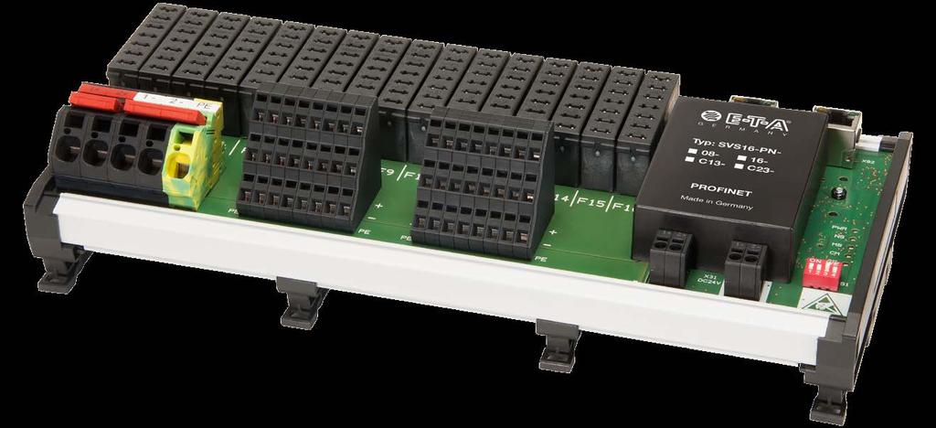
4 1 General The power distribution system SVS16-PN-XX offers selective overcurrent protection, power distribution of load circuits as well as connecting and resetting of outputs. The system is fitted with a fully-fledged PROFINET interface to ensure a consistent communication of status and failure conditions as well as switching / resetting of individual circuits on the DC 24 V level. The system has been designed for rail mounting and has 8 (SVS16-PN-08) or 16 (SVS16-PN-16) slots. The slots can optionally accommodate electronic circuit protectors type ESX10-(S)125 (with reset input and status output), ESX10-(S)115 (with control input and status output) or with the SSRPC E-1048-S7xx (with control input and status output) General mounting guidelines The power distribution system must only be installed by qualified personnel. Only after expert installation must the device be supplied with power. It is only intended for use with safety extra-low voltage (= 24 V DC). Connection to a higher or not reliably disconnected voltage can cause hazardous conditions or damages. The max. total current of the power distribution system must not be exceeded In each load branch the cable cross section and the current rating of the protective component must be adjusted to the current rating of the connected load. The technical data of the used circuit protectors have to be observed. The Machinery Directive 2006/42/EC and EN , Safety of Machines requests special precautions to be taken in the system or machine (e.g. using a safety PLC) to prevent inadvertent start-up of the system or parts of the system. In the event of a failure (short circuit/overload) the load circuit will be disconnected by the circuit breaker/protector. After tripping of the circuit protector, before reset, the cause of tripping (short circuit or overload) has to be remedied. The national standards (e.g. for Germany DIN VDE 0100) and selection of appropriate ingoing and outgoing cables have to be observed. Caution: Electrostatically sensitive devices (ESD). Devices must exclusively be opened by the manufacturer. Disposal guidelines Packaging can be recycles and should generally be brought to re-use. 4

5 2 Bus-capable power distribution system SVS16-PN-XX Connection of the SVS16-PN-XX to the EtherNet/IP network is via PROFINET module and the corresponding RJ45 connectors. Every module used in the SVS16 has a 1 bit output/1 bit input. Consequently either 1 byte input/1 byte output for 8 modules or 2 byte input/2 byte output for 16 modules Overview 2.2. Schematic diagram (SVS16-PN-16 shown) load pcb bus pcb PROFINET-DP Slave SVS16-PN V bus pcb Connection PROFINET RJ45 F1 Line GND SC F2 F15 F16 Line GND SC Line GND SC Line GND SC communication PWR RUN/NS ERR/MS CM CE Load IN+/ PE SO Load IN+/ PE SO Load IN+/ PE SO Load IN+/ PE SO bus pcb communication bus pcb communication bus pcb communication bus pcb communication X1 X2 + + X15 X bus pcb - bus pcb configuration switch X PE DC 24 V / max. 40 A PE PE PE PE X31 DC24V
6 2.3. Termination Supply voltage load module Rated voltage DC 24 V ( V) Total current max. 40 A DC 24 V (+) 1+ / 2+ (2-way) DC 24 V (-) 1- / 2- (2-way) PE PE connected to DC 24 V (-) Termination X21 for type SVS16-PN-XX-C13: 5-pole spring-loaded terminals, (1+/2+/1-/2-/PE) cable cross section max. 10 mm 2 for type SVS16-PN-XX-C23: 5-pole spring-loaded terminals, (1+/2+/1-/2-/PE) cable cross section max. 16 mm 2 screw terminals M Supply voltage bus module Rated voltage DC 24 V ( V) Current consumption max. 250 ma Termination X31 2-pole push-in terminal (1+/2+) cable cross section max. 1.5 mm 2 2-pole push-in terminal (1-/2-) cable cross section max. 1.5 mm Load outputs Rated voltage DC 24 V ( V) Current consumption Termination max. 10 A per terminal block / slot (L+) protected load output (+) (L-) negative return load (-) (PE) PE X1 X8 (X16) for type SVS16-PN-XX-C13: three-level screwless spring-loaded terminals cable cross section max. 1.5 mm 2 for type SVS16-PN-XX-C23: three-level screw-type terminals cable cross section max. 1.5 mm 2 screw terminals M F-slots Slots for the types ESX10-(S)115, ESX10-(S)125 and E-1048-S7xx. SVS16-PN F1...F8 = terminals X1...X8 SVS16-PN F1...F16 = terminals X1...X16 6
7 2.4. Operating modes The operating modes of the unit are set via a DIP switch as follows: ON OFF Switch Description ON condition OFF condition 1 freeze freeze active, a bus error will not affect the condition of the connected load. 2 firm IP IP address configured firmly on admin admin mode active, i.e. DHCP, HICP and possibly web are active 4 (reserve) freeze inactive, a bus error will influence the condition of the connected load, all connected loads will be switched off. IP address configured dynamically (or last active one) All network services except the field bus service are off 2.5. Behaviour in the absence of a bus connection The behaviour of the SVS16-PN in the event of a bus failure (failure of master, interruption of bus line etc.) is determined via the DIP switch 1. The host controller saved the ON/OFF condition in the internal EEPROM. The following phases have to be distinguished during start-up: 1. Switch on supply voltage, no field bus communication yet with the superordinate master. Here the behaviour depends on the DIP switch 1 as follows: a. Freeze active : the switches are activated according to the EEPROM contents, i.e. the status will be set corresponding to the latest status before the supply voltage was switched off b. Freeze inactive : all switches are off. 2. Cyclical master communication active. The master controls the condition of the switches. Changes of the ON/ OFF condition by the master will be stored in the EEPROM of the host controller. 3. Cyclical master communication failed:. a. Freeze active : the switches will be activated according to the EEPROM contents, i.e. they keep the latest state received from the master. b. Freeze inactive : all switches are off. 7
8 2.6. Addressing General information and operating modes Assignment of the device address is via the integral MAC addresses in the device. There are three ways how to set IP addresses allowing access to the device: 1. Firm IP address. The firm IP address is activated by switching the DIP switch 2 to On. The following network parameters will then be activated: IP-address netmask gateway Admin mode: The admin mode is activated via the DIP switch 3. If the admin mode is active, other services to be reached via the network are also active for parameter selection: DHCP, HICP and web. If the address parameters are changed by means of these services, these will be filed in the non-volatile memory and will remain active even after switching the admin mode off. 3. Fieldbus-specific addressing: this function is permanently active and allows address assignment via the fieldbus-specific mechanism (see below for details). The mode firm IP address can be used for resetting the device to a defined address. When activating the mode Firm IP address and the admin mode at the same time, further configuration settings can be carried out under the firm address , even if no other mechanism for address assignment are used. Should the IP address parameters be changed in this condition, the mode Firm IP address has to be selected before a restart. If the mode Firm IP address is inactive, the parameters stored in the non-volatile memory will be valid after start. These parameters can be adjusted via the fieldbus-specific services (e.g. CIP objects) or via the other mechanisms for address adjustment (particularly DHCP, HICP and website). Depending on the DIP switch status the following types of address assignment are possible: Mode Switch 2 (firm IP) Switch 3 (firm IP) Description address assignment only possible via fieldbus-specific mechanisms if no address is assigned via fieldbus, the most recently used address will remain active address assignment possible via fieldbus and all standard mechanisms (see Chapter 2.6.3, e.g. HICP, DHCP, web). if no address is assigned via one of the active protocols, the address most recently used will remain active address will firmly be assigned to address assignment via fieldbus-specific mechanisms possibly nevertheless (temporarily), but will be reset upon re-start as mode 1, but after starting the device the firm IP will be used. As all other protocols for address assignment are active, the address can be changed temporarily. The condition as delivered is mode 1. In condition 1 the latest adjusted condition will remain active. 8
9 Fieldbus-specific unit search / address assignment With PROFINET and Ethernet/IP, fieldbus-specific mechanisms are made available for locating devices in the network and for assigning IP addresses. These mechanisms are, independent of the DIP switch positions (switch 2, switch 3), permanently active and work as follows: Fieldbus Device location Address assignment EtherNet/ IP PROFI- NET EtherCAT device location via CIP identity broadcast via DCP protocol any configured device can be located. via the device manager of the TwinCAT software configuration (incl. DHCP on/off) via the CIP object. via DCP protocol, normally automatically when setting up the connection via the device name. via the device manager of the TwinCAT software Modbus-TCP (none) (none) The fieldbus project planning tool (Step 7/TIA Portal for PROFINET, Rockwell RSLinx Software, via Communication RSWho) or the Rockwell Studio 5000 Environment via EtherNet/IP is used for using these fieldbus-specific mechanisms Standard functions for address assignment The IP address of the device can be set via the following methods via the network when the admin mode is active (see above): - Via the standard TCP/IP-protocols DHCP/BootP. In this case the module always queries for an IP address during start-up via a network broadcast. Prerequisite: the network holds a DHCP/BootP server. If an address has been received, it will be stored as standard address in the flash and be used later, even if no DHCP/BootP server is available any longer. - Via the HMS-controlled HICP protocol (with the Windows software AnybusIPConfig). Here a broadcast is sent by a PC application so that even modules with faulty network settings can be configured. Pre-condition is the installation of an additional software on the customer PC. If an address has been set above, it will be stored in the flash as standard address and be used with immediate effect. - Via the integral web server (if activated). Note - For safety reasons, unnecessary/unused services should be deactivated. As a standard mechanism for addressing is available in Ethernet/IP, the HICP mode should be deactivated (and equally Telnet/FTP or HTTP if unused) Setting of the EtherNet ports Data transmission normally is effected with 10 or 100 Mbit/s in full duplex mode with automatic recognition of MDI/ MDX and 10/100Mbit half/full duplex. 9
10 2.8. Configuration of SVS16-PN The PROFINET cyclic I/O data are provided in a module with 1-byte I/O (for 8 channel SVS16) or with 2-byte I/O (16 channel SVS16). The GSDML file contains two different devices, depending on the type (SVS16-8 / SVS16-16) ( DAP, with the respective order numbers), each with a fixed configuration slot for I/O. The SVS16-PN-XX provides two each bytes input and output data. This means in detail: Output byte 1 (Control/Reset) slot no. F1 F2 F3 F4 F5 F6 F7 F8 binary value 2^0 2^1 2^2 2^3 2^4 2^5 2^6 2^7 decimal value Output byte 2 (Control/Reset) slot no. F9 F10 F11 F12 F13 F14 F15 F16 binary value 2^8 2^9 2^10 2^11 2^12 2^13 2^14 2^15 decimal value The word splits itself in two bytes. Each output byte activates 8 slots with the least significant bit (LSB) of the output byte 1 being assigned to the slot F1. The most significant bit (MSB) of the output byte 1 is assigned to slot F8. Analog to the output byte 1 the least significant bit (LSB) of the output byte 2 is assigned to slot F9 and the most significant bit (MSB) to slot F16. Depending on the population of the SVS16 the following has to be determined: a) slot fitted with E-1048-S7xx (with control input and status output) 1 24 V ON switch on E-1048-S7xx 0 24 V OFF switch off E-1048-S7xx b) slot fitted with ESX10-(S)115 (with control input and status output) 1 24 V ON switch on ESX10-(S) V OFF switch off ESX10-(S)115 c) slot fitted with ESX10-(S)125 (with control input and status output) min. 100 ms min. 100 ms For reset an ESX10-(S)125 in OFF condition a pulse of a duration of min. 100 ms. The ESX10-(S)125 cannot explicitly be switched off. 10
11 Input byte 1 (status) slot no. F1 F2 F3 F4 F5 F6 F7 F8 binary value 2^0 2^1 2^2 2^3 2^4 2^5 2^6 2^7 decimal value Input byte 2 (status) slot no. F9 F10 F11 F12 F13 F14 F15 F16 binary value 2^8 2^9 2^10 2^11 2^12 2^13 2^14 2^15 decimal value Each input byte allows importing status or failure indications of 8 slots. Assignment of the individual slots is identical with the above described assignment of the output bytes (LSB of output byte 1 is assigned to slot F1, MSB to slot F8 etc.). Independent of the devices types the following determinations are valid: 0 device is ON 1 device is OFF and slot is empty This means that the value 256 will be transferred when no circuit breaker was plugged in LED indication for bus communication (PROFINET) The status of the device and the network will be shown by extern LED s. The LEDs indicate the following information: Network status LED RUN / NS Module status LED ERR / MS Offline off Not Initialized off Online (RUN) green Normal Operation green Online (STOP) one flash in green Diagnostic Event(s) Blink flashing green Expection error red Fatal event red Fatal event red Station Name error IP address error Configuration error one flash in red two short flashes in red three short flashes in red Firmware update one flash in green alternate in red, green 11
12 2.10. Signalling of the various operating modes The different operating modes of the power distribution system are indicated as follows: Operating mode Signalling of the operating mode LED CM LED CE LED PWR SVS_SYSTEMINIT 1) green red green 1) green red green 1) green red green SVS_ERROR_CRITICAL yellow red green SVS_ERROR_UNCRITICAL yellow blink red green SVS_STANDALONE (FREEZE) yellow OFF green SVS_NORMAL_MODE green OFF green 1) Color change as LED test Operating modes of the power distribution system Operating mode: SYSTEMINIT After applying the supply voltage the module is in the operating mode. During this period no communication is possible. This mode takes a few seconds. Also the switch setting of the hardware switch S1 is determined. Signalling this mode see table signalling of the operating mode Operating mode: FREEZE Requirement: DIP switch 1 = ON. The master controls the status of connected devices. Or in process of interruption in the bus connection, the devices are driven in accordance to the EEPROM content. Signalling this mode see table signalling of the operating mode Operating mode: UNFREEZE Requirement: DIP switch 1 = OFF. The master controls the status of connected devices. On interruption of the bus, the connected devices are turning off. Signalling this mode see table signalling of the operating mode Operating mode: UNIT_ADRESSING Fixed: The IP address is fix configured to address This requires DIP switch 2 = ON and DIP switch 3 = OFF Admin-Mode: This requires DIP switch 2 = ON and DIP switch 3 = ON. If the Amin Mode is active, the IP address parameters are changed by using its services. Then these parameters are stored in the non-volatile memory and remain active even after the Admin Mode is deactivated. Fieldbus Specified Addressing: This function is always active and allows an address mapping via the fieldbus mechanism. 12
13 3. Firmware of the Anybus version The firmware of the IC module used determines the selection of the GSDML file to be used 13
14 Bedienungsanleitung/Instruction manual B_SVS16-EN_e_ Bestell-Nr. / Ref. number Y Index: - Ausgabe / Issue: 01/2016 / Alle Rechte vorbehalten / All rights reserved E-T-A Elektrotechnische Apparate GmbH Industriestraße ALTDORF DEUTSCHLAND Tel Fax info@e-t-a.de.
Instruction Manual Power Distribution System SVS16-EN-XX
 Instruction Manual Power Distribution System SVS16-EN-XX 2 Contents 1 General...4 1.1 General mounting guidelines...4. 2 Bus-capable power distribution system SVS16-EN-XX...5 2.1. Overview...5 2.2. Schematic
Power distribution system SVS16-PB
 Power distribution system SVS1PB Description The new power distribution and remote output system type SVS1 PBxx offers selective overcurrent protection, power distribution of load circuits and switching,
G5 Weighing Instrument
 G5 Weighing Instrument Program version 1.4.X Fieldbus Option Manual PM and RM types CONTENTS 1. Introduction... 1-1 General... 1-1 Module installation... 1-2 Ordering information... 1-3 2. Modules...
User Manual Gateway component for EtherNet/IP
 User Manual Gateway component for EtherNet/IP PR100066 1/7/2016 Table of Contents KUNBUS GmbH Table of Contents 1 General Information... 3 1.1 Disclaimer... 3 1.2 Notes Regarding this User Manual... 4
Profinet Module. User Manual. Contents
 User Manual Contents 1 Important User Information... 2 2 Installation... 3 3 Connection... 4 4 Device Configuration... 5 5 Operation... 7 6 Packet Structures... 8 7 Network Design... 16 8 Specifications...
mipick Pick-by-Light System
 mipick Pick-by-Light System User Manual microsyst Systemelectronic GmbH Exclusive UK and Ireland Agent: Metrix Electronics Ltd tel: 0845 034 3234 www.metrix-electronics.com Index 1 SYSTEM OVERVIEW 4 2
Operating instructions IO-Link master CabinetLine AL19xx
 Operating instructions IO-Link master CabinetLine AL19xx 80273036/00 02/2018 1 Preliminary note Technical data, approvals, accessories and further information at www.ifm.com. 2 Safety instructions Read
RAD-DO8-IFS. I/O extension module, eight digital transistor outputs. Data sheet. 1 Description
 I/O extension module, eight digital transistor outputs Data sheet 105364_en_00 PHOENIX CONTACT 2013-03-26 1 Description The I/O extension module can be used in conjunction with Radioline wireless modules
Ethernet/IP Module. User Manual. Contents
 User Manual Contents 1 Important User Information... 2 2 Installation... 3 3 Connection... 4 4 Device Configuration... 5 5 Operation... 8 6 Packet Structures... 9 7 Network Design... 18 8 Specifications...
Date Revision Change(s) 29/07/ First version
 29/07/ First version") Revision overview Revision overview Date Revision Change(s) 29/07/2016 0 First version Copyright 2016 Indu-Sol GmbH We reserve the right to amend this document without notice. We continuously work on further
Revision overview Revision overview Date Revision Change(s) 29/07/2016 0 First version Copyright 2016 Indu-Sol GmbH We reserve the right to amend this document without notice. We continuously work on further
BL compact multiprotocol fieldbus station for Industrial Ethernet 8 Analog Inputs for Current or Voltage BLCEN-8M12LT-4AI-VI-4AI-VI
 On-machine Compact fieldbus I/O block EtherNet/IP, Modbus TCP, or PROFINET slave Integrated Ethernet Switch 10 Mbps / 100 Mbps Two 4-pole M12, D-coded, connectors for fieldbus connection 2 rotary switches
Solid State Remote Power Controller E /627
 Solid State Remote Power Controller E--623/62 Description The E-T-A Solid State Remote Power Controllers E--623/62 are electronic control modules suitable for inductive loads such as electromagnetic valves
Ethernet/SIOX Gateway Applicable to firmware ver 1.0
 ES2 Ethernet/SIOX Gateway p 2 TELEFRANG AB TABLE OF CONTENTS Ethernet/SIOX Gateway Applicable to firmware ver 1.0 General Description The ES2 module is a Gateway between a LAN/WAN Ethernet network and
crio PN Installation Instructions V0.2/ COMSOFT
 crio PN Installation Instructions V0.2/10.06.2015 COMSOFT crio PN-Installation- V0.2/10.06.2015 i:\icp\project\700391_crio_pn\anwenderdoku\installation\version_0.2\crio_pn_e.doc Revision History Version
ETHERNET/IP & PROFINET MODULE
 5108 en - 2013.12 / a Ready Stop Run Start Trip Local Reset LCL RMT er w Po n Er 1 2 us k 1 /RX k 2 /RX at Lin TX St Lin TX 2 14702.A r ro 1 give e b s to i l a nu se r a u m d This o the en t ETHERNET/IP
BL compact multiprotocol fieldbus station for Industrial Ethernet 8 Analog Inputs for Thermocouple Elements BLCEN-8M12LT-4AI-TC-4AI-TC
 On-machine Compact fieldbus I/O block EtherNet/IP, Modbus TCP, or PROFINET slave Integrated Ethernet Switch 10 Mbps / 100 Mbps Two 4-pole M12, D-coded, connectors for fieldbus connection 2 rotary switches
MODBUS TCP MODULE INSTRUCTIONS. for use with WSIQ2/WSE
 INSTRUCTIONS MODBUS TCP MODULE for use with WSIQ2/WSE WorldWide Electric Corporation Phone: 1-800-808-2131 Fax: 1-800-711-1616 www.worldwideelectric.net Product Compatibility This communications module
Communication settings: Network configuration can be done via the Anybus IP configuration setup tool or via the on board Web server
 SmartLinx EtherNet/IP instruction and use APPLICATION GUIDE Objective: Show the user how to configure and use an EtherNet/IP SmartLinx communication module. AG082415 While every effort was made to verify
Network configuration can be done via the Anybus IP configuration setup tool or via the on board Web server.
 SmartLinx EtherNet/IP instruction and use Objective: Show the user how to configure and use a EtherNet/IP SmartLinx communication module. AG052813 While every effort was made to verify the following information,
BL compact multiprotocol fieldbus station for Industrial Ethernet 8 Analog Inputs for Current or Voltage BLCEN-8M12LT-4AI-VI-4AI-VI
 On-machine Compact fieldbus I/O block EtherNet/IP, Modbus TCP, or PROFINET slave Integrated Ethernet Switch 10 Mbps / 100 Mbps supported Two 4-pole M12, D-coded, connectors for fieldbus connection 2 rotary
Quick Start Guide PROFINET Switch 4/8-port. Version. 1en.
 Quick Start Guide PROFINET Switch 4/8-port Version 1en www.helmholz.de Contents 1. Introduction 3 2. Preparing the PROFINET switch 4 3. Project planning for PROFINET switch 4 4. Setting the port properties
SK CU4-EIP-C Part number:
 SK CU4-EIP-C Part number: 275 271 519 EtherNet/IP Internal Bus Interface The bus interface may only be installed and commissioned by qualified electricians. An electrician is a person who, because of their
The accessories described in this manual are of the highest quality, carefully designed and built in order to ensure excellent performance.
 INTRODUCTION Thank you for choosing our product. The accessories described in this manual are of the highest quality, carefully designed and built in order to ensure excellent performance. This manual
User manual Gateway component Sercos
 User manual Gateway component Sercos DO0227R00 6/28/2016 Table of Contents KUNBUS GmbH Table of Contents 1 General Information... 3 1.1 Disclaimer... 3 1.2 Notes Regarding this User Manual... 3 1.3 Validity...
CODESYS 3 Programmable Gateway for the BL67 I/O System Multiprotocol Ethernet gateway for PROFINET, EtherNet/IP and Modbus TCP BL67-PG-EN-V3
 CODESYS V3 programmable acc.to IEC 61131-3 Ethernet and USB programming interface Protection class IP67 Integrated power supply LEDs for display of PLC status, supply voltage, group and bus errors Programmable
PROFINET MODULE. Communications module. User Guide. This manual is to be given to the end user en / a. Power. Error. Status.
 5201 en - 2014.09 / a Stop Ready Run Start Trip Reset Local LCL RMT Power This manual is to be given to the end user Error Status Link 1 TX/RX 1 Link 2 1 2 TX/RX 2 14702.A PROFINET MODULE Communications
Anybus X-gateway. PROFINET IRT (2.32) Interface NETWORK GUIDE
 Interface NETWORK GUIDE") Anybus X-gateway PROFINET IRT (2.32) Interface NETWORK GUIDE SCM-1202-028-EN 1.1 ENGLISH Important User Information Liability Every care has been taken in the preparation of this document. Please inform
Anybus X-gateway PROFINET IRT (2.32) Interface NETWORK GUIDE SCM-1202-028-EN 1.1 ENGLISH Important User Information Liability Every care has been taken in the preparation of this document. Please inform
SK CU4-PNT-C Part number:
 SK CU4-PNT-C Part number: 275 271 515 PROFINET IO Internal Bus Interface The bus interface may only be installed and commissioned by qualified electricians. An electrician is a person who, because of their
Type code. BLCEN-8M12LT-4AI-VI-8XSG-P Ident-No Nominal system voltage 24 VDC. Nominal current Vo Max. current Vo
 On-machine Compact fieldbus I/O block EtherNet/IP, Modbus TCP, or PROFINET slave Integrated Ethernet Switch 10 Mbps / 100 Mbps Two 4-pole M12, D-coded, connectors for fieldbus connection 2 rotary switches
RAD-DI8-IFS. I/O extension module with 8 digital inputs or 2 pulse inputs. INTERFACE Data sheet. 1 Description
 I/O extension module with 8 digital inputs or 2 pulse inputs INTERFACE Data sheet 0483_en_00 PHOENIX CONTACT 203-04-05 Description The I/O extension module can be used in conjunction with Radioline wireless
Contents User Manual For PIM
 PIM User Manual 503287 - User Manual For PIM Contents 1. Introduction... 3 2. Navigate this Document... 3 3. Safety Summary... 4 4. Trademarks and Copyrights... 4 5. Contact Information... 5 6. Documentation
Quick Start Guide PN/CAN-Gateway. Version. 1 en. from FW
 Quick Start Guide PN/CAN-Gateway Version 1 en from FW 1.00 www.helmholz.com Content 1. Introduction 3 2. Preparation of the PN/CAN-Gateway 3 3. Plan PN/CAN-Gateway 4 4. Configure PN/CAN-Gateway 5 5. Add
Device manual Diagnostic electronics with PROFINET-IO interface for vibration sensors VSE150
 Device manual Diagnostic electronics with PROFINET-IO interface for vibration sensors VSE150 80257046/00 10/2017 Contents 1 Preliminary note................................................. 4 1.1 Explanation
BL compact multiprotocol fieldbus station for Industrial Ethernet SSI Interface BLCEN-1M12MT-1SSI
 On-machine Compact fieldbus I/O block EtherNet/IP, Modbus TCP, or PROFINET slave Integrated Ethernet Switch 10 Mbps / 100 Mbps Two 4-pole M12, D-coded, connectors for fieldbus connection 2 rotary switches
Electronic Overcurrent Protector REF16-S
 Electronic Overcurrent Protector REF6-S Description Type REF6-S is an extension of the product group»electronic Overcurrent Protection«for DC 2 V applications. It provides selective protection for all
Anybus.NET Bridge PROFIBUS
 Anybus.NET Bridge PROFIBUS STARTUP GUIDE SCM-1203-046/SP2063 1.1 ENGLISH Important User Information Liability Every care has been taken in the preparation of this document. Please inform HMS Industrial
BL67 electronic module 4 analog inputs for current/voltage BL67-4AI-V/I
 Independent of the type of fieldbus and connection technology used Protection class IP67 LEDs indicate status and diagnostic Electronics galvanically separated from the field level via optocouplers 4 analog
Operating Instructions Electronic Circuit Protector ESX10-TC-DC 12 V
 Y 310 410 01 Version: 03/2012 Operating Instructions Electronic Circuit Protector ESX10-TC-DC 12 V Specifications: Warning This device is only suitable for operation at 24 VDC (safety extra-low voltage).
Fieldbus slave modules w/o I/Os
 tem SLIO Fieldbus slave modules w/o I/Os tem 500S tem 300S tem 100V Order number Figure Type IM 053CAN, CANopen slave IM 053DN, DeviceNet slave IM 053DP, PROFIBUS-DP slave IM 053EC, EtherCAT slave General
Operating Manual FPGA-based High-Speed Micro-PLC
 ZX20T Operating Manual FPGA-based High-Speed Micro-PLC Zander GmbH & Co. KG Am Gut Wolf 15 52070 Aachen, Deutschland info@zander-aachen.de www.zander-aachen.de Part No.: E61-335-10 Edition: H03 This document
Operating Instructions IO-Link Master with Modbus TCP interface DataLine 8 Ports IP 65 / IP 66 / IP 67 AL1342
 Operating Instructions IO-Link Master with Modbus TCP interface DataLine 8 Ports IP 65 / IP 66 / IP 67 AL1342 IO-Link: 1.1.2 ifm firmware: 2.1.28 or higher LR DEVICE: 1.3.1.x or higher English 7391206
Quick Start Guide PN/CAN Gateway Layer 2. Version. 2 en. ab FW
 Version 2 en ab FW 1.02 Quick Start Guide PN/CAN Gateway Layer 2 www.helmholz.de Content 1. Introduction 3 2. Preparation of the PN/CAN Gateway 3 3. Configure PN/CAN Gateway 4 4. PN/CAN Gateway settings
Du line. Dupline Field- and Installationbus Dupline Ethernet Modbus/TCP Gateway Type G G Type Selection
 Dupline Field- and Installationbus Dupline Ethernet Modbus/TCP Gateway Type G 3891 0052 Built-in Dupline channel generator Modbus/TCP Slave 10 and 100 Mbit operation, full or half duplex Twisted pair cables
BL compact Multiprotocol Station for Industrial Ethernet 16 Digital PNP Inputs BLCEN-16M8LT-8DI-P-8DI-P
 On-Machine compact fieldbus I/O blocks EtherNet/IP, Modbus TCP or PROFINET slave Integrated Ethernet switch 10 Mbps/100 Mbps Two 4-pin, D-coded M12 connectors for fieldbus connection 2 rotary coding switches
ECN module MGC-PRO MicroDrive
 Technical Manual ECN module MGC-PRO MicroDrive This technical manual is a supplement for the operating instructions for the MHTM TM MicroDrive barriers, describing the ECN module. Before using the ECN
Device manual Profibus encoder. RM30xx RN30xx /00 06/2013
 Device manual Profibus encoder RM30xx RN30xx 706355/00 06/2013 Contents 1 Preliminary note................................................. 4 1.1 Symbols used...............................................
BL67 electronic module 8 configurable digital channels, PNP, channel diagnostics, 0.5 A BL67-8XSG-PD
 Independent of the type of fieldbus and connection technology used Protection class IP67 LEDs indicate status and diagnostic Electronics galvanically separated from the field level via optocouplers 8 configurable
Chapter 5: Communications 5 1 SR55 Communications Overview 5 2
 Chapter 5 Table of Contents Chapter 5: Communications 5 1 SR55 Communications Overview 5 2 Modbus Serial Communications Overview 5 2 Modbus TCP Network Communications Overview 5 2 EtherNet/IP Network Communications
Operating Manual UMB ISO Converter ISOCON Order Number: 8160.UISO
 Order Number: 8160.UISO Status: V3; 17.09.2010c G. Lufft Mess- und Regeltechnik GmbH, Fellbach, Germany 1 TABLE OF CONTENTS PLEASE READ BEFORE USE... 3 DESCRIPTION... 5 UMB ISO CONVERTER ISOCON... 6 CONFIGURATION...
Additional instructions Videographic recorder LINAX DR3000. PROFINET Device
 Additional instructions Videographic recorder LINAX DR3000 PROFINET Device Table of contents: 1 General information... 3 1.1 Scope of delivery... 3 1.2 Firmware history... 3 1.3 Connections... 4 1.3.1
Compact Multiprotocol I/O Module for Ethernet 8 digital PNP inputs, input diagnostics per channel TBEN-S1-8DIP-D
 EtherNet/IP, Modbus TCP, or PROFINET slave Integrated Ethernet switch 10 Mbps / 100 Mbps 2 x male M8, 4-pin, Ethernet-Fieldbus connection Glass fiber reinforced housing Shock and vibration tested Fully
INDUSTRIAL COMMUNICATION AND INFRASTRUCTURE for your PROFINET application
 INDUSTRIAL COMMUNICATION AND INFRASTRUCTURE for your PROFINET application www.helmholz.de MAC: ----- FCN RST Ext. V DC 8... V + FE IN IN PWR RUN BF SF Helmholz TB-C PROFINET IO Helmholz TB-C PROFINET IO
DALI Professional Controller-4. Control unit Operating instructions
 LI Professional Controller-4 Control unit Operating instructions Contents Safety... 4 General instructions 4 Safety instructions 4 Description... 5 Purpose and application 5 Configuration 5 Design 5 Connections
RAD-DOR4-IFS. I/O extension module, 4 digital relay outputs. INTERFACE Data sheet. 1 Description
 I/O extension module, 4 digital relay outputs INTERFACE Data sheet 104834_en_01 PHOENIX CONTACT 2013-01-21 1 Description The RAD-DOR4-IFS I/O extension module can be used in conjunction with Radioline
Fieldgate SFG500. Technical Information. Intelligent Ethernet/PROFIBUS gateway
 Technical Information Fieldgate Intelligent Ethernet/PROFIBUS gateway Application Fieldgate is a system component that provides an independent access route to a PROFIBUS network. It may be used in a variety
DF PROFINET IO CPCI. Installation Instructions V1.3/ KUNBUS
 DF PROFINET IO CPCI Installation Instructions V1.3/23.06.2017 KUNBUS DF PROFINET IO CPCI Installation Instructions - V1.3/23.06.2017 h:\dokumente\project\700361_df_profinet_io_controller\anwenderdoku\installation\cpci\version_1.3\df_profinet_io_cpci_e.doc
Compact Multiprotocol I/O Module for Ethernet 8 IO-Link Master Channels 4 Universal Digital PNP Channels, 2 A, Channel Diagnostics TBEN-L5-8IOL
 Type designation Ident no. 6814017 Supply Supply voltage Admissible range Voltage supply connection 24 VDC 18 30 VDC Total current max. 9 A per voltage group Total current V1 + V2 max. 11 A 20.4 28.8 VDC
Data sheet CPU 015PN (015-CEFPR01)
") Data sheet CPU 015PN (015-CEFPR01) Technical data Order no. Module ID - General information Note - Features Technical data power supply 015-CEFPR01 CPU 015PN Powered by SPEED7 Work memory [KB]: 256...512
Data sheet CPU 015PN (015-CEFPR01) Technical data Order no. Module ID - General information Note - Features Technical data power supply 015-CEFPR01 CPU 015PN Powered by SPEED7 Work memory [KB]: 256...512
Operating Instructions IO-Link Master with EtherNet/IP interface DataLine 4 Ports IP 65 / IP 66 / IP 67 AL1320
 Operating Instructions IO-Link Master with EtherNet/IP interface DataLine 4 Ports IP 65 / IP 66 / IP 67 AL1320 IO-Link: 1.1.2 ifm firmware: 2.1.28 or higher LR DEVICE: 1.3.1.x or higher English 7391156
Copyright: December 2017 Nidec Issue: E
 General Information The manufacturer accepts no liability for any consequences resulting from inappropriate, negligent or incorrect installation or adjustment of the optional parameters of the equipment
CVIC II - CVIL II - CVIR II - MULTICVIL II - Memory Mapping - Manual
 1/36 CVIC II - CVIL II - CVIR II - MULTICVIL II - Memory Mapping - Manual N - Copyright 2011, St Herblain France All rights reserved. Any unauthorized use or copying of the contents or part thereof is
XPSMF40. Main. Safety module name. Monitoring safety detection discrete input Monitoring safety dialogue discrete output
 Product datasheet Characteristics XPSMF4000 Preventa safety PLC compact - Safe Ethernet Main Range of product Product or component type Safety module name Safety module application Preventa Safety automation
C-DIAS EtherNet/IP Slave CIP 022
 C-DIAS-ETHERNET/IP SLAVEMODUL CIP 022 C-DIAS EtherNet/IP Slave CIP 022 The C-DIAS EtherNet/IP CIP 022 slave module is an interface module between the C-DIAS control system and EtherNet/IP bus. Technical
Compact Multiprotocol I/O Module for Ethernet 16 Digital PNP Outputs TBEN-L4-16DOP
 EtherNet/IP, Modbus TCP, or PROFINET slave Integrated Ethernet switch Supports 10 Mbps/100 Mbps 2 x M12, 4-pin, D-coded, Ethernet fieldbus connection Glass fiber reinforced housing Shock and vibration
SCHMIDT Sensor interface PROFIBUS Instructions for use
 SCHMIDT Sensor interface PROFIBUS Instructions for use Table of contents 1 Important information... 3 2 Intended use... 4 3 Electrical connection... 4 4 Signalizations... 7 5 Startup... 9 6 Technical data...
CODESYS 3 Programmable Gateway for the BL20 I/O System Multiprotocol Ethernet Gateway for PROFINET, EtherNet/IP and Modbus TCP BL20-PG-EN-V3
 Programmable multiprotocol Ethernet gateway for PROFINET, EtherNet/IP and Modbus TCP OPC-Server CODESYS V3 programmable acc.to IEC 61131-3 Ethernet and USB programming interface Protection type IP20 Integrated
RAD-DAIO6-IFS. I/O extension module, 1 analog input/output, 2 digital wide-range inputs/outputs. INTERFACE Data sheet.
 I/O extension module, 1 analog input/output, 2 digital wide-range inputs/outputs INTERFACE Data sheet 104832_en_01 PHOENIX CONTACT 2013-01-21 1 Description The RAD-DAIO6-IFS I/O extension module can be
Date Revision Change(s) First version Firmware Update 1.5
 First version Firmware Update 1.5") Revision overview Revision overview Date Revision Change(s) 04.06.2015 0 First version 30.06.2016 1 Firmware Update 1.5 Copyright 2016 Indu-Sol GmbH We reserve the right to amend this document without
Revision overview Revision overview Date Revision Change(s) 04.06.2015 0 First version 30.06.2016 1 Firmware Update 1.5 Copyright 2016 Indu-Sol GmbH We reserve the right to amend this document without
INSTRUCTION MANUAL WCS-Interface Module, DeviceNet
 FACTORY AUTOMATION INSTRUCTION MANUAL WCS-Interface Module, DeviceNet WCS-DG210 Part. No. 202340 / DOCT-1305 / 11. june 2007 1 Working principle............................ 6 2 Installation and commissioning.................
Operating instructions RFID evaluation unit DTE / / 2016
 Operating instructions RFID evaluation unit DTE101 80005398 / 01 06 / 2016 Contents 1 Preliminary note...4 1.1 Notes on this document...4 1.2 Symbols used...4 2 Safety instructions...4 2.1 General...4
EX2 Ethernet/SIOX Controller p 2. General Description Block Diagram
 EX2 Ethernet/SIOX Controller p 2 TELEFRANG AB Ethernet/SIOX Controller EX2 General Description The EX2 module is a Controller/Gateway between a LAN/WAN Ethernet network and a SIOX fieldbus providing remote
Ethernet Module MGC-PRO MicroDrive
 Technical Manual Ethernet Module MGC-PRO MicroDrive This technical manual is a supplement to the operating instructions "Barrier MHTM TM MicroDrive" (5815,51) and describes the Ethernet module. Before
Manual. Fieldbus Interface DFE33B EtherNet/IP and Modbus/TCP. Edition 10/ / EN
 Drive Technology \ Drive Automation \ System Integration \ Services Fieldbus Interface DFE33B EtherNet/IP and Modbus/TCP Edition 10/2008 16725611 / EN Manual SEW-EURODRIVE Driving the world Contents 1
AS-i Safety Relay Output Module with Diagnostic Slave
 AS-i Safety Relay Output Module with Diagnostic Slave User Manual...supports the requirements for AS-i Safety up to SIL3 Revision date: 2016-03-9 Subject to modifications without notice. Generally, this
Compact multiprotocol I/O module for Ethernet 4 Analog Inputs, Configurable as Voltage, Current, RTD or Thermocouple TBEN-S2-4AI
 Each channel can be selected for voltage, current, RTD, resistance, thermocouple Measuring ranges: Voltage: +/-500 mv, +/-100 mv, +/-50 mv, +/-1 V, 0 / 1-5 V, +/-10 V, 0 / 2-10 V, Current: 0 / 4 20 ma,
Altivar - Lexium. Option modules DANGER S1A S1A /8 VW3A3601 / VW3A3608 VW3A3616 / VW3A3627 VW3A3619 VW3A3720 VW3A3721 VW3M3308
 S1A4559106 Option modules Altivar - Lexium 01 / 08 16 / 27 19 09 28 3725 3M3301 07 18 3720 3721 3M3308 HAZARD OF ELECTRIC SHOCK, EXPLOSION, OR ARC FLASH DANGER Only appropriately trained persons who are
Operating and mounting instructions
 General Usage IPAS DALI Gateways bring together the crossfunctional KNX installation bus and the lighting control specific DALI-Bus (IEC 60929). Lights with cost-effective, digital DALI ECGs can therefore
Revision. Decentralized Drive and Application Control MOVIPRO ADC with PROFINET interface * _1017*
 Drive Technology \ Drive Automation \ System Integration \ Services *24741337_1017* Revision Decentralized Drive and Application Control MOVIPRO ADC with PROFINET interface Edition 10/2017 24741337/EN
ETHERNET/MFC 010 Technical Datasheet
 ETHERNET/MFC 010 Technical Datasheet EtherNet/IP interface box in combination with MFC 010 Seamless integration into EtherNet/IP environments Integrated web server for easy configuration, maintenance and
Indu-Sol GmbH Specialist in fieldbus technologies INBLOX. User Manual. Diagnostic and service tools for PROFIBUS
 Indu-Sol GmbH Specialist in fieldbus technologies INBLOX User Manual Diagnostic and service tools for PROFIBUS List of revisions Date Revision Change(s) 05/10/2011 0 First version Copyright 2011 Indu-Sol
SmartRail I/O Ethernet Base HE599ETX300
 MAN--EN Specifications / Installation SmartRail I/O Ethernet Base HE599ETX INTRODUCTION SmartRail I/O is a real-time, modular I/O system that supports a variety of Ethernet and Fieldbus Communication architectures.
UNIGATE UNIGATE CM CM GATEWAY SERIES. CAN/CANopen TO ALL FIELDBUSES AND INDUSTRIAL ETHERNET. Easy installation. Norm compliant.
 UNIGATE GATEWAY SERIES UNIGATE CM CM Easy installation Norm compliant Ready-to-use Configurable Designed & manufactured in Germany THE INTELLIGENT SOLUTION FOR: ETHERNET TCP/IP CAN/CANopen TO ALL FIELDBUSES
EGW1-IA3-MB User s Manual
 www.exemys.com Rev. 0 1 Products are in constant evolution to satisfy our customer needs. For that reason, the specifications and capabilities are subject to change without prior notice. Updated information
ILBPB24DO32. Inline Block IO Module for PROFIBUS With 32 Digital Outputs. AUTOMATIONWORX Data Sheet 6889_en_04. Description
 Inline Block IO Module for PROFIBUS With 32 Digital Outputs AUTOMATIONWORX Data Sheet 6889_en_04 Description PHOENIX CONTACT - 03/2007 & & ' ) The ILB PB 24 DO32 module is designed for use within a PROFIBUS
Kit for Simple I/O Communication via Ethernet Modbus/TCP/ EtherNet/IP / PROFINET in IP67 TI-BL67-EN-S-8
 Type code Ident no. 1545153 Number of channels 8 Dimensions (W x L x H) 204 x 145 x 77.5 mm A special software (function module) for integration in PLC systems is not required. Cable max. 50 m between
Date Revision Change(s) First version
 First version") Revision overview Revision overview Date Revision Change(s) 04.06.2015 0 First version Copyright 2015 Indu-Sol GmbH We reserve the right to amend this document without notice. We continuously work on further
Revision overview Revision overview Date Revision Change(s) 04.06.2015 0 First version Copyright 2015 Indu-Sol GmbH We reserve the right to amend this document without notice. We continuously work on further
Type code. TBEN-S2-4IOL Ident no Supply. Total current max. 4A per voltage group
 M12 slots for IO-Link Master, 5-pin IO-Link Protocol 1.1 Male M8, 4-pin, for power supply Separated power groups for safety shutdown Glass-fiber reinforced housing Shock and vibration tested Fully potted
Compact multiprotocol I/O module for Ethernet 16 digital PNP outputs TBEN-L1-16DOP
 EtherNet/IP, Modbus TCP, or PROFINET slave Integrated Ethernet switch Supports 10 Mbps/100 Mbps 2 x M12, 4-pin, D-coded, Ethernet fieldbus connection 7/8" males, 5-pin, for power supply Separated power
Rack Installation Instruction
 Rack Installation Instruction Date of issue: Date of publication: May 2017 This document replaces the following documents: ControlPlex Rack I_19BGTCP_d_200916 Editor: Elektrotechnische Apparate GmbH Industriestraße
FACTORY AUTOMATION. MANUAL ICE1-8DI8DO-G60L-V1D ICE1-8DI8DO-G60L-C1-V1D ICE1-16DI-G60L-V1D Fieldbus Modules with Multiprotocol Technology
 FACTORY AUTOMATION MANUAL ICE1-8DI8DO-G60L-V1D ICE1-8DI8DO-G60L-C1-V1D ICE1-16DI-G60L-V1D Fieldbus Modules with Multiprotocol Technology R With regard to the supply of products, the current issue of the
Supplementary device manual EtherCAT interface in the AS-i controllere A AC1391 AC1392
 Supplementary device manual EtherCAT interface in the AS-i controllere A AC1391 AC139 firmware version RTS.x target from 15 for CoDeSys from version.3 English 739071_00_UK 01-0- Contents Revision: 16 December
Valve island VM10 with PROFINET Interface 8, 10, 12 or 16 stations. Operation & Service Manual
 Valve island VM10 with PROFINET Interface 8, 10, 12 or 16 stations Operation & Service Manual Change history: The Change history reflects all changes of the User Guide, which were done after the initial
Anybus-CC CFW-11. User s Manual. Phone: Fax: Web: -
 Anybus-CC CFW-11 User s Manual Anybus-CC User s Manual Series: CFW-11 Language: English Document Number: 0899.5750 / 06 Publication Date: 09/2013 CONTENTS CONTENTS... 3 ABOUT THE MANUAL... 6 ABBREVIATIONS
DF PROFI II PCIe. Installation Instructions V Project No.: 5302 Doc-ID.: DF PROFI II PCIe KUNBUS
 DF PROFI II PCIe Installation Instructions V1.6 27.02.2017 Project No.: 5302 Doc-ID.: DF PROFI II PCIe KUNBUS h:\dokumente\project\5302_df_profi_ii\anwenderdoku\installation\pcie\kunbus\version_1.5\df
DF PROFI II CPCI. Installation Instructions V Project No.: 5302 Doc-ID.: DF PROFI II CPCI KUNBUS
 DF PROFI II CPCI Installation Instructions V1.7 27.02.2017 Project No.: 5302 Doc-ID.: DF PROFI II CPCI KUNBUS h:\dokumente\project\5302_df_profi_ii\anwenderdoku\installation\cpci\kunbus\version_1.6\df
Installation Manual TH LINK PROFINET. Version: EN Copyright 2014 Softing Industrial Automation GmbH
 Installation Manual TH LINK PROFINET Version: EN-201410-1.00 Copyright 2014 Softing Industrial Automation GmbH Disclaimer of liability The information contained in these instructions corresponds to the
Compact Multiprotocol I/O Module for Ethernet 16 Digital PNP Inputs TBEN-L5-16DIP
 EtherNet/IP, Modbus TCP, or PROFINET slave Integrated Ethernet switch Supports 10 Mbps/100 Mbps 2 x M12, 4-pin, D-coded, Ethernet fieldbus connection Glass fiber reinforced housing Shock and vibration
Programmable Set for Simple I/O Communication via PROFIBUS-DP in IP67 TI-BL67-PG-DP-S-8
 Type designation Ident no. 1545097 Number of channels 8 Dimensions (W x L x H) 204 x 145 x 77.5 mm CoDeSys-programmable acc. to IEC 61131-3 Cable max. 50 m between interface and read/write head 12 Mbps
Compact multiprotocol I/O module for Ethernet 8 digital PNP inputs, input diagnostics per channel TBEN-S1-8DIP-D
 Male M8, 4-pin, for power supply Glass-fiber reinforced housing Shock and vibration tested Fully potted module electronics Protection classes IP65 / IP67 / IP69K Type code Ident no. 6814034 Supply Supply
TECHNICAL DOCUMENTATION
 TECHNICAL DOCUMENTATION Read this manual prior to performing any task! ABB Automation Products GmbH Eppelheimer Straße 82 69123 Heidelberg, Germany Telephone: +49 62 21 701 1444 Fax: +49 62 21 701 1382