Product Description. Ordering Information. Nexto Series
|
|
|
- Evelyn Morris
- 5 years ago
- Views:
Transcription

1 Product Description is a powerful and complete serie of Programmable Logic Controllers (PLCs) with exclusive and innovative features, targeted for covering control systems requirements from medium to large applications or high performance industrial machines. The diversity of available CPU models offer the ideal solution for every application, with high performance and a flexible architecture, allowing the use in applications ranging from large process automation to fast time-critical machinery automation. Besides, it combines high connectivity with the current high-speed industrial fieldbuses. CPUs were designed to fulfill several customers demands. Due to its compact and rugged body, excellent performance and fast I/Os update time provided by a unique high-speed communication bus, CPUs are the best choice for the most demanding control applications. In complex applications, where reliability, availability and remote I/O operation is required, CPUs are also a great choice due to its different redundant topologies and bus expansion possibilities. CPUs provide an innovative and unique enhanced diagnostics services. They take the user to a whole new diagnostics experience. By using a switch located on top of the module and a built-in compact graphical LCD display, the user has direct access to extensive information regarding I/Os, fieldbus interfaces and many other modules on the application. Finally, CPUs feature several communication interfaces such as serial and Ethernet ports, a minisd card interface and full IEC programming languages. Its main features are: Up to 96 Kbytes of %I points and 96 Kbytes of %Q points Large memory capacity for user application and user data Up to 112 Kbytes of retain memory High-speed 32-bit processing Floating point unit Up to 2 serial ports Up to 2 Ethernet interfaces at front panel minisd card interface (CPUs NX3010, NX3020 and NX3030) Enhanced diagnostics services System messages log Event oriented data reporting (CPUs NX3020 and NX3030) IEC Server protocol (CPUs NX3005, NX3020 and NX3030) OPC DA/UA Server, EtherCAT Master, SNMP Client and EtherNet/IP Scanner/Adapter protocols (in some CPU models) Support clock synchronization via SNTP or via IEC Web server features Redundancy mode for high availability applications (CPU NX3030) Integrated power supply (CPUs NX3003, NX3004 and NX3005) Integrated digital IO (CPU NX3003) Counters and fast outputs (CPU NX3003) One Touch Diag IEC compliant Real-time clock (RTC) Compact and modern design Free of moving parts (fans, active cooling, etc.) Ordering Information Included Items The product NX3003 s package contains the following items: NX3003 module 12-terminal connector with fixing 18-terminal connector with fixing Installation guide Altus S. A. 1
2 The product NX3004 and NX3005 s package contains the following items: NX3004 or NX3005 module 6-terminal connector with fixing Installation guide The product NX3010, NX3020 and NX3030 s package contains the following items: NX3010, NX3020 or NX3030 module Installation guide Product Code The following codes should be used to purchase the product: Code NX3003 NX3004 NX3005 NX3010 NX3020 NX3030 Description CPU, 1 Ethernet port, 1 serial channel, 14 digital inputs, 10 digital outputs, loacal IO modules support and power supply integrated CPU, 1 Ethernet port, 1 serial channel, remote rack expansion support and power supply integrated CPU, 1 Ethernet port, 1 serial channel, remote rack expansion support, power supply integrated and user web pages support High-speed CPU, 1 Ethernet port, 2 serial channels, memory card interface and remote rack expansion support High-speed CPU, 2 Ethernet ports, 2 serial channels, memory card interface and remote rack expansion support High-speed CPU, 2 Ethernet ports, 2 serial channels, memory card interface, remote rack expansion and redundancy support Related Products The following products must be purchased separately when necessary: Code MT8500 AL-2600 AL-2301 AL-2306 AL-2319 AL-1729 AL-1748 AL-1752 AL-1753 AL-1754 AL-1761 AL-1762 AL-1763 NX9101 NX9202 NX9205 NX9210 NX9404 NX9405 NX9406 NX9020 Description MasterTool IEC XE RS-485 network branch and terminator RS-485 network cable (up to 1000 meters) RS-485 network cable (up to 500 meters) RJ45-RJ45 Cable RJ45-CMDB9 Cable CMDB9-CFDB9 Cable CMDB9-CMDB9 Cable CMDB9-CMDB25 Cable CMDB9-CFDB9 Cable CMDB9- CMDB9 Cable CMDB9- CMDB9 Cable CMDB9-Terminal Block Cable 32 GB memory card MicroSD with minisd and SD adapter RJ45-RJ45 2 m Cable RJ45-RJ45 5 m Cable RJ45-RJ45 10 m Cable 6-terminal connector with fixing 12-terminal connector with fixing 18-terminal connector with fixing 2 slot base for panel assembly Altus S. A. 2


3 Notes: MT8500: MasterTool IEC XE is available in four different versions: LITE, BASIC, PROFESSIONAL and ADVANCED. For more details, please check MasterTool IEC XE User Manual - MU AL-2600: This module is used for branch and termination of RS-422/485 networks. For each network node, an AL-2600 is required. The AL-2600 that is at the ends of network must be configured with termination, except when there is a device with active internal termination, the rest must be configured without termination. AL-2301: Two shielded twisted pairs cable without connectors, used for networks based on RS-485 interface, with 1000 meters of maximum length. AL-2306: Two shielded twisted pairs cable without connectors, used for networks based on RS-485 interface, with 500 meters of maximum length. AL-2319: Two RJ45 connectors for programming the CPUs of the and Ethernet point-to-point with another device with Ethernet interface communication. AL-1729: RS-232C standard cable with one RJ45 connector and one DB9 male connector for communication between CPUs of the and other Altus products of the DUO Series, Piccolo Series and Ponto Series. AL-1748: RS-232C standard cable with one DB9 male connector and 1 DB9 female connector for communication between CPUs of the and Altus products of the Cimrex Series. AL-1752: RS-232C standard cable with two DB9 male connectors for communication between CPUs of the and Altus products of the H Series and ix Series. AL-1753: RS-232C standard cable with one DB9 male connector and one DB25 male connector for communication between CPUs of the and Altus products of the H Series. AL-1754: RS-232C standard cable with one DB9 male connector and one DB9 female connector for o communication between CPUs of the and Altus products of the Exter Series or Serial port, RS-232C standard, of a microcomputer. AL-1761: Cable RS-232C standard with two DB9 male connectors for communication between CPUs of the and other Altus products of the AL series. AL-1762: Cable RS-232C standard with two DB9 male connectors for communication between CPUs of the. AL-1763: Cable with one DB9 male connector and terminal block for communication between CPUs of the and products with RS-485/RS-422 standard terminal block. NX9202/NX9205/NX9210: Cables used to interconnect the bus expansion modules. NX9404: 6 terminal conector used on NX3004 and NX3005. NX9405: 12 terminal conector used on NX3003. NX9406: 18 terminal conector used on NX3003. NX9420: 2 slot base for panel assembly. Used by NX3003, NX3004 and NX3005 CPUs, which don t require IO modules on the bus. Innovative Features brings to the user several innovations in utilization, supervision and system maintenance. These features were developed focusing a new experience in industrial automation. The list below shows some new features that users will find in the CPUs: Battery Free Operation: does not require any kind of battery for memory maintenance and real time clock operation. This feature is extremely important because it reduces the system maintenance needs and allows the use in remote locations where maintenance can be difficult to be performed. Besides, this feature is environmentally friendly. Multiple Block Storage: Several kinds of memories are available to the user in CPUs, offering the best option for any user needs. These memories are divided in volatile memories and non-volatile memories. For volatile memories, CPUs offer addressable input (%I), addressable output (%O), addressable memory (%M), data memory and redundant data memory. For applications that require non-volatile functionality, CPUs bring retain addressable memory (%Q), retain data memory, persistent addressable memory (%Q), persistent data memory, program memory, source code memory, CPU file system (doc, PDF, data) and memory card interface. One Touch Diag: One Touch Diag is an exclusive feature that brings to PLCs. With this new concept, the user can check diagnostic information of any module present in the system directly on CPU s graphic display with one single press in the diagnostic switch of the respective module. OTD is a powerful diagnostic tool that can be used offline (without supervisor or programmer), reducing maintenance and commissioning times. Altus S. A. 3
4 OFD On Board Full Documentation: CPUs are capable of storing the complete project documentation in its own memory. This feature can be very convenient for backup purposes and maintenance, since the complete information is stored in a single and reliable place. ETD Electronic Tag on Display: Another exclusive feature that brings to PLCs is the Electronic Tag on Display. This new functionality brings the process of checking the tag names of any I/O pin or module used in the system directly to the CPU s graphic display. Along with this information, the user can check the description, as well. This feature is extremely useful during maintenance and troubleshooting procedures. DHW Double Hardware Width: modules were designed to save space in user cabinets or machines. For this reason, delivers two different module widths: Double Width (two backplane rack slots are required) and Single Width (only one backplane rack slot is required). This concept allows the use of compact I/O modules with a highdensity of I/O points along with complex modules, like CPUs, fieldbus masters and power supply modules. High-speed CPU: All CPUs were designed to provide an outstanding performance to the user, allowing the coverage of a large range of applications requirements. For example: NX3010, NX3020 and NX3030 Nexto CPUs can execute a sum, multiplication and subtraction instruction in less than 15 ns for integer type values and in less than 23 ns for real type values. Nexto CPUs are able to perform 1,000 PIDs loops in less than 5 ms. if Product Design Award 2012: was the winner of if Product Design Award 2012 in industry + skilled trades group. This award is recognized internationally as a seal of quality and excellence, considered the Oscars of the design in Europe. Altus S. A. 4
5 Product Features Common General Features Backplane rack occupation Programming languages Tasks Online changes Serial interfaces Real time clock (RTC) Watchdog Status and diagnostic indication One Touch Diag (OTD) Logic to protective earth Logic to Ethernet interfaces Ethernet interfaces to protective earth NX3003, NX3004, NX3005, NX3010, NX3020, NX sequential slots Instruction List (IL) Structured Text (ST) Ladder Diagram (LD) Sequential Function Chart (SFC) Function Block Diagram (FBD) Continuous Function Chart (CFC) Cyclic (periodic) Event (software interrupt) External (hardware interrupt) Freewheeling (continuous) Status (software interrupt) NX3003 COM 1: 1 x RS-485 NX3004/NX3005 COM 1: 1 x RS-485 / RS-422 NX3010/NX3020/NX3030 COM 1: 1 x RS-232C NX3010/NX3020/NX3030 COM 2: 1 x RS-485 / RS-422 Resolution of 1 ms and maximum variance of 2 s per day Graphic display, LEDs, web pages and CPU s internal memory 1000 Vac / 1 minute 1000 Vac / 1 minute Operating temperature 0 to 60 C Storage temperature -25 to 75 C Relative humidity 5 to 96 %, non-condensing Conformal coating IP Level IP 20 Module dimensions (W x H x D) x x mm Package dimensions (W x H x D) x x mm Weight 350 g Weight with package 400 g Notes: Tasks: Task is an object used to call POUs. A Task can be triggered by period, events or can run in freewheeling mode. Each task can call one or more POUs. Real time clock (RTC): Retain time, period that the real time clock will keep updating date and time after a power off, is 15 days for operation at 25 C. At the maximum product operation temperature, retain time is reduced to 10 days. : The Logic term refers to the internal interfaces such as processors, memories and backplane rack interfaces. Conformal coating: Conformal coating protects the electronic components inside the product from moisture, dust and other harsh elements to electronic circuits. Altus S. A. 5
6 Specific General Features NX3003 NX3004 NX3005 NX3010 NX3020 NX3030 Addressable input variables memory (%I) 32 KB 32 KB 32 KB 32 KB 64 KB 96 KB Addressable output variables memory (%Q) 32 KB 32 KB 32 KB 32 KB 64 KB 96 KB Addressable variables memory (%M) 16 KB 16 KB 16 KB 16 KB 32 KB 64 KB Symbolic variables memory 2 MB 2 MB 3 MB 4 MB 5 MB 6 MB Maximum amount of memory configurable as retentive or persistent 7.5 KB 7.5 KB 7.5 KB 64 KB 112 KB 112 KB Total redundant data memory Addressable input variables memory (%I) Addressable output variables memory (%Q) KB Addressable variables memory (%M) Symbolic variables memory Program memory 3 MB 3 MB 6 MB 4 MB 6 MB 8 MB Source code memory (backup) 32 MB 32 MB 40 MB 40 MB 80 MB 120 MB User files memory 16 MB 16 MB 16 MB 16 MB 32 MB 32 MB Maximum number of tasks Bus expansion redundancy support - Maximum number of expansion bus Maximum number of I/O modules on the bus Ethernet TCP/IP local interface Maximum number of additional Ethernet TCP/IP interface modules Ethernet TCP/IP interface redundancy support Maximum number of PROFIBUS-DP network (using master modules PROFIBUS- DP) 736 KB 80 KB 64 KB 512 KB PROFIBUS-DP network redundancy support Redundancy support (half-clusters) HotSwap support - Electronic Tag on Display (ETD) - Event oriented data reporting (SOE) Protocol DNP3 DNP3 Maximum event queues size Web pages development (available trough the HTTP protocol) Altus S. A. 6
7 MODBUS protocol (Master/Slave/Client/Server) OPC DA protocol (Server) OPC UA protocol (Server) EtherCAT protocol (Master) SNMP protocol IEC protocol (Server) EtherNet/IP protocol (Scanner/Adapter) - - SNTP protocol (Client, for clock syncronism) Power supply integrated Current consumption from backplane rack power supply ma 1000 ma 1000 ma Power dissipation 4 W 4 W 4 W 4 W 5 W 5 W Standards IEC IEC CE 2014/35/EU (LVD) and 2014/30/EU (EMC) - RoHS /65/EU UL Listed - UL (file E473496) - DNV-GL Type Approval DNVGL-CG-0339 (TAA000013D) - EAC - CU TR 004/2011 (LVD) and CU TR 020/2011 (EMC) - Altus S. A. 7
8 Notes: Addressable input variables memory (%I): Area where the addressable input variables are stored. Addressable variables means that the variables can be accessed directly using the desired address. For instance: %IB0, %IW100. Addressable input variables can be used for mapping digital or analog input points. As reference, 8 digital inputs can be represented per byte and one analog input point can be represented per two bytes. Total addressable output variables memory (%Q): Area where the addressable output variables are stored. Addressable variables means that the variables can be accessed directly using the desired address. For instance: %QB0, %QW100. Addressable output variables can be used for mapping digital or analog output points. As reference, 8 digital outputs can be represented per byte and one analog output point can be represented per two bytes. The addressable output variables can be configured as retain, persistent or redundant variables, but the total size is not modified due to configuration. The NX3030 CPU allows defining an area of redundant variables inserted inside of the addressable output variables %Q. The subset of addressable output variables memories are part of the total size of available memory. Addressable variables memory (%M): Area where the addressable marker variables are stored. Addressable variables means that the variables can be accessed directly using the desired address. For instance: %MB0, %MW100. Symbolic variables memory: Area where the symbolic variables are stored. Symbolic variables are IEC variables created in POUs and GVLs during application development, not addressed directly in memory. Symbolic variables can be defined as retain or persistent. In these cases, it will be used the memory area of retain symbolic variables memory or persistent symbolic variables memory respectively. The PLC system allocates variables in this area, so the space available for the allocation of variable user-created is lower than given in the table. The occupation by the system variables depends on the project characteristics (number of modules, drivers, etc...), so it is recommended to observe the space available in the compilation of messages of MasterTool IEC XE. Persistent and Retain symbolic variables memory: Area where are allocated the retentive symbolic variables. The retentive data keep its respective values even after a CPU s cycle of power down and power up. The persistent data keep its respective values even after the download of a new application in the CPU. In versions and lower for NX3004 and for NX3010, NX3020 and NX3030, the retentive and persistent symbolic memories and addressable output variables memory (%Q) used to have a fixed maximum size. On Table bellow, it s possible to consult the maximum sizes allowed in these older versions. In versions above the ones mentioned, the CPUs allow flexible retentive and persistent memory sizes. Retentive addressable output variables memory (%Q) Persistent addressable output variables memory (%Q) NX3004 NX3010 NX3020 NX Kbytes 8 Kbytes 16 Kbytes 16 Kbytes 2 Kbytes 8 Kbytes 16 Kbytes 48 Kbytes Retentive symbolic variables memory 2 Kbytes 32 Kbytes 48 Kbytes 32 Kbytes Persistent symbolic variables memory 1,5 Kbytes 16 Kbytes 32 Kbytes 16 Kbytes Total redundant data memory: Redundant data memory is the maximum memory area that can be used as redundant memory between two redundant CPUs. This value is not a different memory, note that the sum of all redundant variables (addressable input variable, addressable output variable, addressable variable, symbolic variable, retain symbolic variable, persistent symbolic variable) must be less than or equal to the available redundant data memory. Program memory: Program memory is the maximum size that can be used to store the user application. This area is shared with source code memory, being the total area the sum of program memory and source code memory. Source code memory (backup): This memory area is used as project backup. If the user wants to import the project, MasterTool IEC XE will get the information required in this area. Care must be taken to ensure that the project saved as a backup is up to date to avoid the loss of critical information. This area is shared with source code memory, being the total area the sum of program memory and source code memory. User files memory: This memory area offers another way for the user to store files such as doc, pdf, images, and other files. This function allows data recording as in a memory card. More information can be found at CPUs User Manual MU Maximum number of tasks: The maximum number of tasks defined for each CPU model and each project profile can be found at CPUs User Manual MU Redundancy support (half-clusters): The firmware version or onwards supports redundancy of NX3030 CPUs. Event oriented data reporting (SOE): The date types can be found at CPUs User Manual MU Maximum number of I/O modules on the bus: The maximum number of I/O modules on the bus refers the sum of all modules on the local bus and on the expansion bus. Maximum number of PROFIBUS-DP networks: From MasterTool IEC XE version 1.22 and onwards, 4 PROFIBUS-DP networks are supported for NX3020 and NX3030 CPUs. Previous versions support 2 PROFIBUS-DP networks. The limit of PROFIBUS-DP masters is 4, which means that 2 redundant networks can be used at most. Altus S. A. 8
9 COM 1 (NX3003) Connector Physical interface Communication direction RS-485 maximum transceivers 32 Termination Baud rate Protocols earth Logic to Serial Port Serial Port to protection NX3003 terminals RS-485 RS-485: half duplex (optional through parameter) 200, 300, 600, 1200, 1800, 2400, 4800, 9600, 19200, 38400, 57600, bps Master/Slave MODBUS RTU Open protocol Not isolated 1000 Vac / 1 minute Notes: RS-485 maximum transceivers: Is the maximum number of RS-485 interfaces that can be used on the same bus. COM 1 (NX3004/NX3005) Connector Physical interface Communication direction RS-422 maximum transceivers RS-485 maximum transceivers 32 Termination Baud rate Protocols earth Logic to Serial Port Serial Port to protection NX3004 and NX3005 Shielded female DB9 RS-422 or RS-485 (depending on the selected cable) RS-422: full duplex RS-485: half duplex 11 (1 transmitter and 10 receivers) (optional via cable selection) 200, 300, 600, 1200, 1800, 2400, 4800, 9600, 19200, 38400, 57600, bps Master/Slave MODBUS RTU Open protocol 1000 Vac / 1 minute 1000 Vac / 1 minute Notes: Physical interface: Depending on the configuration of the used cable, it s possible to choose the kind of physical interface: RS-422 or RS-485. The list of cables can be found at Related Products section. RS-422 maximum transceivers: Is the maximum number of RS-422 interfaces that can be used on the same bus. RS-485 maximum transceivers: Is the maximum number of RS-485 interfaces that can be used on the same bus. Altus S. A. 9
10 COM 1 (NX3010/NX3020/NX3030) Connector Physical interface Modem signals Baud rate Protocols Logic to Serial Port Serial Port to protection earth NX3010, NX3020, NX3030 Shielded female DB9 RS-232C RTS, CTS, DCD 200, 300, 600, 1200, 1800, 2400, 4800, 9600, 19200, 38400, 57600, bps Master/Slave MODBUS RTU Open protocol Not isolated 1000 Vac / 1 minute COM 2 (NX3010/NX3020/NX3030) Connector Physical interface Communication direction RS-422 maximum transceivers RS-485 maximum transceivers 32 Termination Baud rate Protocols earth Logic to Serial Port Serial Port to protection NX3010, NX3020 and NX3030 Shielded female DB9 RS-422 or RS-485 (depending on the selected cable) RS-422: full duplex RS-485: half duplex 11 (1 transmitter and 10 receivers) (optional via cable selection) 200, 300, 600, 1200, 1800, 2400, 4800, 9600, 19200, 38400, 57600, bps Master/Slave MODBUS RTU Open protocol 1000 Vac / 1 minute 1000 Vac / 1 minute Notes: Physical interface: Depending on the configuration of the used cable, it s possible to choose the kind of physical interface: RS-422 or RS-485. The list of cables can be found at Related Products section. RS-422 maximum transceivers: Is the maximum number of RS-422 interfaces that can be used on the same bus. RS-485 maximum transceivers: Is the maximum number of RS-485 interfaces that can be used on the same bus. Altus S. A. 10
11 NET 1 Connector Auto crossover Maximum cable length NX3003, NX3004, NX3005, NX3010, NX3020, NX3030 Shielded female RJ m Cable type UTP or ScTP, category 5 Baud rate Physical layer Data link layer Network layer Transport layer Application layer Diagnostic Ethernet interface to Serial Port 10/100 Mbps 10/100 BASE-TX LLC (logical link control) IP (Internet Protocol) TCP (Transmission Control Protocol) and UDP (User Datagram Protocol) MODBUS TCP Client and Server MODBUS RTU via TCP Client and Server MasterTool IEC XE programming protocol DNP3 Server (event oriented data reporting) IEC Server SNTP Client (clock synchronism) EtherCAT Master OPC DA Server OPC UA Server SNMP Agent (Ethernet network management) EtherNet/IP Scanner/Adapter LEDs - green (speed), yellow (link/activity) Note: Application layer: The CPU models that support these application protocols should be consulted in the Specific General Features section. Altus S. A. 11
12 NET 2 Connector Auto crossover Maximum cable length NX3020, NX3030 Shielded female RJ m Cable type UTP or ScTP, category 5 Baud rate Physical layer Data link layer Network layer Transport layer Application layer Diagnostic Ethernet interface to Serial Port Ethernet interface to Ethernet interface 10/100 Mbps 10/100 BASE-TX LLC (logical link control) IP (Internet Protocol) TCP (Transmission Control Protocol) and UDP (User Datagram Protocol) MODBUS TCP Client and Server MODBUS RTU via TCP Client and Server MasterTool IEC XE programming protocol DNP3 Server (event oriented data reporting) IEC Server SNTP Client (clock synchronism) EtherCAT Master OPC DA Server OPC UA Server SNMP Agent (Ethernet network management) EtherNet/IP Scanner/Adapter LEDs - green (speed), yellow (link/activity) Note: Application layer: The CPU models that support these application protocols should be consulted in the the Specific General Features section. Power Supply Nominal input voltage Maximum output power Maximum output current Input voltage Maximum input current (in-rush) Maximum input current Input to logic Input to protective earth Wire size Polarity inversion protection Internal auto recovery fuse Output short-circuit protection Overcurrent protection NX Vdc 10 W 2 A 19.2 to 30 Vdc 30 A 1.4 A 1000 Vac / 1 minute 0.5 mm² No Altus S. A. 12
13 Nominal input voltage Maximum output power Maximum output current Input voltage Maximum input current (in-rush) Maximum input current Maximum input voltage interrupt time Input to output Input to protective earth Input do functional earth Wire size Polarity inversion protection Internal auto recovery fuse Output short-circuit protection Overcurrent protection NX3004, NX Vdc 15 W 3 A 19.2 to 30 Vdc 30 A 1.4 A Vdc 1000 Vac / 1 minute 1000 Vac / 1 minute 0.5 mm² Note: Maximum output power: For the NX3004 and NX3005 CPUs, using modules I/O NextoJet, you can extend and get to use 20 W of power output. See Application Note NAP152 to meet the restrictions to use this limit. Digital Input NX3003 Input type Sink type 1 Number of inputs 10 Connector configuration I4, I5, I6, I7, I8, I9, I10, I11, I12 and I13 24 Vdc Input voltage 15 to 30 Vdc for logic level 1 0 to 5 Vdc for logic level 0 Input impedance 4.95 kω Input maximum current Vdc Input state indication Input update time Normal 1 ms Input to output 2.5 ms Input filter 100 µs by hardware 2 to 255 ms by software Input to logic Input to fast outputs Input to counters Input to Ethernet Input to power supply Input to protective earth Note: Input filter: The input filter sampling is done in the MainTask (or through update function), therefore it is recommended to set values multiples of the task interval. Altus S. A. 13
14 Fast Digital Input Number of counters Connector configuration Input voltage Input impedance Input maximum current Configuration mode Counting direction control Counting input detection edge Data format NX3003 Up to 4 32-bit configurable fast counters (may be used as normal inputs or external interrupt) I0, I1, I2 and I3 24 Vdc 15 to 30 Vdc for logic level 1 0 to 5 Vdc for logic level kω Vdc 1-input modes Normal digital input External interrupt Unidirectional counter (increase or decrease) 2-input modes Unidirectional counter with zeroing input Bidirectional counter (increase and decrease) Bidirectional counter (with counting direction) Bidirectional counter (increase and decrease) Encoder (quadrature 2x) Encoder (quadrature 4x) By software or hardware Upwards, active at logic level 1 (for interrupt, unidirectional counter, bidirectional counter and encoder 2x modes) Both edges (for encoder 4x mode) Signed 32-bit integer Operation limit ± 2,147,483,648 Maximum input frequency Configurable parameters Fast input to power supply Fast inpus to logic Fast input to normal outputs Fast input to simple inputs Fast input to Ethernet Fsat input to protective earth 200 khz Digital inputs Counters comparing outputs External interrupts Not isolated Note: Configuration mode: The configuration modes define I0, I1, I2 and I3 inputs behavior. Altus S. A. 14
15 Transistor Digital Output NX3003 Common outputs number 6 Connector configuration Q4, Q5, Q6, Q7, Q8 and Q9 Maximum current Vdc by output 4 30 Vdc total Output type Transistor source Switching time 200 µs off to on 30 Vdc 500 µs on to off 30 Vdc Maximum switch frequency with load 250 Hz State indication Can be seen through standard product screens Protections TVS diode at all transistor outputs Operation voltage 19.2 to 30 Vdc Output impedance 500 mω Output to logic Output to fast outputs Output to fast inputs Output to Ethernet Output to power supply Output to protective earth Note: Switching time: Required to shut down an output, but it depends on the load. Altus S. A. 15
16 Fast Digital Output Number of outputs 4 Connector configuration Maximum current Output type Pulse generation maximum frequency Minimum pulse 24 Vdc State indication Protections Opetation voltage Output impedance Output modes Functions executed by software Output registers access Fast output to power supply Fast outpus to logic Fast output to normal outputs Fast output to simple inputs Fast output to Ethernet Fsat output to protective earth NX3003 Q0, Q1, Q2 and Q Vdc by output 2 30 Vdc total Transistor source ma MINIMUM LOAD MINIMUM PULSE TIME 400 Ω 320 ns Through static reserved operands TVS diode at all transistor outputs 19.2 to 30 Vdc 700 mω Normal, PTO, VFO and PWM PTO Writing of number of pulses to be generated Writing of acceleration and deaccelerationnumber of pulses Start/end outputs operation Fast outputs diagnostics Fast outputs current state monitoring Symbol variables Not isolated VFO/PWM Writing of the frequency value to be generated (1 Hz to 200 khz). Writing of outputs dutty cycle (1% to 100%) Start/end of outputs operations Fast outputs diagnostics.\ Altus S. A. 16
17 Diagnostics LEDs CPUs NX3004, NX3005, NX3010, NX3020 and NX3030 have one LED to indicate diagnostics (DG LED) and one LED to indicate watchdog occurrence (WD LED). More information about diagnostics LEDs can be found at Status and Diagnostic Indicators section. Graphic Display CPUs have a graphic display used to show status and diagnostics of the entire system, including specific diagnostics of each additional module. The display also offers an easy-to-use menu that brings to the user a fast way to read or set some parameters, such as: internal temperature (read only); graphic display contrast and IP address for each NET interface (read only). More information about how to use the graphic display can be found at CPUs User Manual - MU Memory Card Interface The memory cards can be used for different kinds of data storage, such as user s logs, web pages, project documentation and source files. More information about how to use memory card Interface can be found at CPUs User Manual - MU Maximum capacity Minimum capacity Type File system Safe card removal NX3010, NX3020, NX Gbytes 2 Gbytes minisd FAT32, by pressing MS switch Notes: Maximum capacity: The memory card capacity must be less than or equal to this limit for correct operation on Nexto CPU, otherwise the Nexto CPU may not detect the memory card or even present problems during data transfer. Minimum capacity: The memory card capacity must be greater than or equal to this limit for correct operation on Nexto CPU, otherwise the Nexto CPU may not detect the memory card or even present problems during data transfer. File system: It is recommended to format the memory card using the Nexto CPU, otherwise it may result in performance loss in the memory card interface. The copy of application to/from memory card is available only in firmware version onwards and MasterTool IEC XE version 1.22 onwards. Altus S. A. 17
18 NX8000 NX3030 NX4010 NX5001 NX5001 NX5000 NX5000 NX5000 NX5000 NX8000 NX3030 NX4010 NX5001 NX5001 NX5000 NX5000 NX5000 NX5000 CPUs CPU Redundancy offers CPU redundancy. The redundant CPUs can be located in different racks (known as half-clusters). In the redundant architecture, the system will have one CPU running (active CPU) and another one acting as the standby CPU, standby CPU is capable of automatic switchover in case of a primary controller failure. This means that critical processes are not affected by control system hardware failures. The result is increased productivity and minimized downtime. The communication between the CPUs is done at the end of each scan cycle through two high-speed redundancy links. The examples below demonstrate two redundant modes provided by. More information about how to configure and use CPU s redundant features can be found at CPUs User Manual - MU Half-Cluster Redundancy This redundancy option uses two racks with one CPU and one redundancy interface module in each rack. In this case, each rack is called half-cluster. Each half-cluster also can have one or more fieldbus master modules that are responsible for communicating with all remote I/Os. When an error at the active half-cluster occurs, the standby half-cluster takes over and its fieldbus master module becomes the bus master of the fieldbus network. This application is easy to set-up, with no special programming or parameterization needed by the user. In this redundant mode, the CPU and the redundancy link module must be placed side by side. The figure below brings an example of rack with a half-cluster redundant topology: SCADA OPC PX Diagram Notes: 1 - At the core of a two half-cluster redundant system, there is a pair of redundant CPUs. 2 - The links between two half-clusters have two channels. So, failures at individual channels will not affect system performance. 3 - Configuration of both systems shall be identical (half-clusters). 4 - This example has network modules with protocols based on Ethernet. There are two network modules for each purpose: a control network and a supervision network for SCADA. 5 - The redundancy panel PX2612 is optional to half-cluster redundancy. It must be used when the redundancy with panel PX2612 option is selected during the MasterTool IEC XE wizard setup. Altus S. A. 18
19 Compatibility with Other Products There are some incompatibilities between CPUs and MasterTool IEC XE. Consult the following table to know which MasterTool IEC XE version should be used. CPU s software version NX3003 NX3004 NX3005 NX3010, NX3020, NX3030 Compatible version of MasterTool IEC XE or lower 1.00 to to to to to to to or higher or higher or higher 2.07 to or higher or higher or higher or higher or higher or higher or higher or higher or higher or higher or higher 3.11 Note: Compatibility between versions: There are some limitations to functionality, some are only available from a certain version. See the section of the User Manual MasterTool IEC XE - MU on the functionality to check the availability of certain characteristic in a specific version of programmer. Altus S. A. 19


20 Physical Dimensions NX3004 and NX3005 Dimensions in mm. Altus S. A. 20
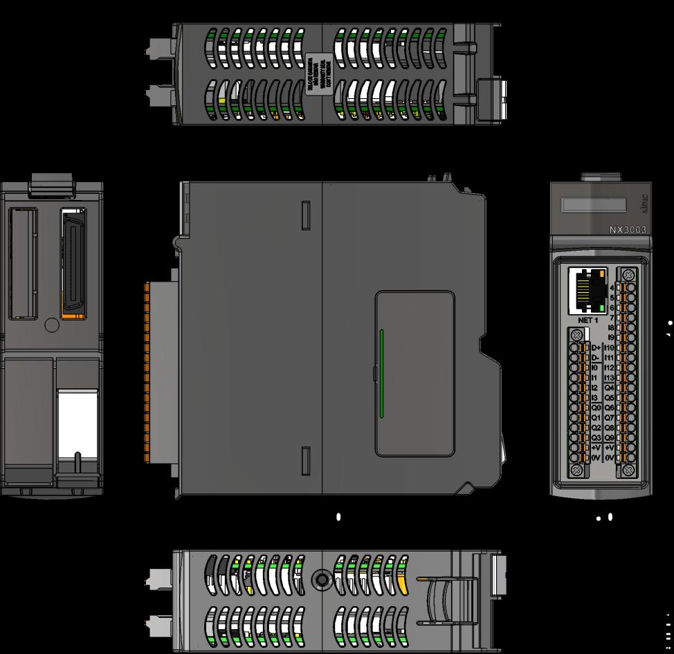

21 NX3003 Dimensions in mm. Altus S. A. 21

22 NX3010, NX3020 and NX3030 Dimensions in mm. Installation All information about electrical installation, mechanical assembly and module insertion can be found at CPUs User Manual - MU Configuration CPUs were developed to be used with products. All products are configured through MasterTool IEC XE. Information about the right procedures to add/remove modules to/from the system can be found at User Manual MU Information about CPU configuration can be found on the CPUs User Manual - MU Programming CPUs use the IEC standard languages, which are IL, ST, LD, SFC and FBD. IL and ST are textual languages and they are similar to Assembly and C languages respectively, while LD, SFC and FBD languages are graphical. LD uses the representation of relays and blocks and it is similar to relay diagrams. SFC uses the representation of a sequence diagram, allowing an easy way to view a sequence of events. FBD uses an arrangement of function blocks, allowing a clear view of functions performed on each action. CPUs also offer a sixth language, CFC. The programming is performed on the MasterTool IEC XE interface. The IDE enables the use of six languages in the same project, thus providing the best features that each language can offer to the user, resulting in efficient application developments, allowing easy documentation and future maintenance. Altus S. A. 22
23 For more information about programming, see the MasterTool IEC XE User Manual - MU299609, MasterTool IEC XE Programming Manual - MP399609, the IEC standard or the CPUs User Manual - MU Maintenance Altus recommends that all modules connections be checked and that all dust or any kind of dirt located at the module s enclosure be removed at least every 6 months. CPUs offer five important features to assist the user during maintenance: Electronic Tag on Display, One Touch Diag and status and diagnostics indicators, web page with complete status and diagnostics list and status and diagnostics mapped to internal memory. Electronic Tag on Display and One Touch Diag Electronic Tag on Display and One Touch Diag are important features that provides for the user the option to check the tag, description and diagnostics related to a given module directly on the CPU display. Electronic Tag on Display and One Touch Diag are easy-to-use features. To check the tag and diagnostics of a given module, it s required only one short press (shorter than 1 s) on its diagnostic switch. After pressing once, CPU will start to scroll tag information and diagnostic information of the module. To access the respective description for the module just long press (longer than 1 s) the diagnostic switch of the respective module. More information about Electronic Tag on Display can be found at User Manual MU and at Nexto Series CPUs User Manual MU Status and Diagnostic Indicators All CPUs have a graphic display that brings useful status and diagnostics to the user, such as application states (run and stop), minisd card status, serial interfaces activity (RX and TX) and others. In addition, CPUs also provide two LEDs that are used to indicate status and diagnostics. The tables below show the meaning of each state of DG LED and WD LED: DG (Diagnostic) WD (Watchdog) Green color Red color Description Causes Priority Off Off Not used No power supply. Hardware problem. On Off All applications running (Run Mode) - 3 (Lower) Off On All Application stopped (Stop Mode) - 3 (Lower) Blinking 2x Off Bus modules with diagnostic Blinking 3x Off Forced data Off Blinking 4x Bus configuration/hardware error At least one module, including CPU, has some active diagnostic. Some memory area is forced by the user via MasterTool IEC XE. The bus is not correctly configured or the bus is damaged (Higher) Red color Description Causes Priority Off No watchdog indication Normal operation. 3 (Lower) Blinking 1x Application watchdog User application watchdog. 2 On Hardware watchdog Module malfunction. 1 (Higher) Notes: Software Watchdog: To clear the watchdog indication, the module must be disconnected from the power supply or the application must be reset. This watchdog happens when the duration of the user application execution is larger than the configured watchdog time. Hardware Watchdog: To clear any watchdog indication, such as WD LED or in the variable Reset.bWatchdogReset, the module must be disconnected from the power supply. Web Page with Complete Status and Diagnostic List Another way to access diagnostic information on is via web pages. CPUs have an embedded web page server that provides all status and diagnostic information that can be accessible using a simple browser on a computer, tablet or smartphone. Altus S. A. 23
24 Diagnostics via Variables The list of all module specific status and diagnostics can be found on the CPUs User Manual - MU Manuals For correct application and utilization, CPUs User Manual - MU must be consulted. For further technical details, configuration, installation and programming of the table below should be consulted. This table is only a guide of some relevant documents that can be useful during the use, maintenance, and programming of NX3003, NX3004, NX3005, NX3010, NX3020 and NX3030. The complete and updated table containing all documents of can be found at User Manual MU Document code Description Language CE Technical Characteristics English CT Série Nexto Caracteristicas Técnicas Portuguese CS Serie Nexto Especificaciones y Configuraciones Spanish CR Technical Characteristics Russian MU User Manual English MU Manual de Utilização Série Nexto Portuguese MU Manual Del Usuario Serie Nexto Spanish MU CPUs User Manual English MU Manual de Utilização UCPs Série Nexto Portuguese MU Manual del Usuario UCPs Serie Nexto Spanish MU MasterTool IEC XE User Manual English MU Manual de Utilização MasterTool IEC XE Portuguese MU Manual del Usuario MasterTool IEC XE Spanish MP MasterTool IEC XE Programming Manual English MP Manual de Programação MasterTool IEC XE Portuguese MP Manual de Programación MasterTool IEC XE Spanish Altus S. A. 24
Product Description. Ordering Information. Nexto Series. Included Items. Product Code
 Product Description is a powerful and complete Programmable Logic Controller (PLC) with unique and innovative features. Due to its flexibility, smart design, enhanced diagnostics capabilities and modular
8 AI RTD Module NJ6020
 Product Description is a powerful and complete Programmable Logic Controller (PLC) Series with unique and innovative features. Due to its flexibility, smart design, enhanced capabilities and modular architecture,
Hadron Xtorm Series Remote Terminal Units
 Hadron Xtorm Series Remote Terminal Units www.beijerelectronics.com Overcoming your challenges Fast: superior processing speed and high performance protocols Rugged: rugged design for operation in critical
Ponto Series CPUs. Product Description. Ordering Information
 Product Description The Ponto Series CPUs present an extended integration of functions, on-line programming, high memory capacity and integrated serial ports. The PO3142 model has three serial interfaces
Programmable Logic Controllers. and Components for Industrial Automation. altus. evolution in automation.
 Programmable Logic Controllers and Components for Industrial Automation altus www.altus.com.br evolution in automation Segmentation Every automation system features unique characteristics that require
Series. Programmable Controllers.
 Series Programmable Controllers www.messungautomation.co.in Control in your hands Flexible: from medium to large systems, redundant or distributed Reliable: high reliability for safety instrumented systems
Product Description. Altus S. A. 1
 Product Description The PO5064 and PO5065 modules are Ponto Series modular PROFIBUS-DPV1 slave heads for PROFIBUS fieldbus that can use all I/O modules from this Series. They can be connected to HMIs (keyboards
PLC PFC200 Controller PFC200 CS 2ETH RS
 0-202 PLC PFC200 Controller PFC200 CS 2ETH RS Marking area Serial interface RJ-4 RJ-4 ACT X2 LNK ETH ACT X LNK X3 RS232/4 U U U4 U3 U2 U STOP RESET 0-202 SYS I/O MS NS U RST SD 0 02 A B 24V 0V + + Status
Data sheet CPU 115 (115-6BL02)
") Data sheet CPU 115 (115-6BL02) Technical data Order no. 115-6BL02 Type CPU 115 General information Note - Features 16 (20) inputs 16 (12) outputs from which are 2 PWM 50 khz outputs 16 kb work memory,
Data sheet CPU 115 (115-6BL02) Technical data Order no. 115-6BL02 Type CPU 115 General information Note - Features 16 (20) inputs 16 (12) outputs from which are 2 PWM 50 khz outputs 16 kb work memory,
Data sheet VIPA CPU 115DP (115-6BL22)
") Data sheet VIPA CPU 115DP (115-6BL22) Technical data Order no. Type 115-6BL22 VIPA CPU 115DP General information Note - Features Work memory [KB]: 16 Load memory [KB]: 24 Onboard 16x DI / 12x DO / 4x DIO
Data sheet VIPA CPU 115DP (115-6BL22) Technical data Order no. Type 115-6BL22 VIPA CPU 115DP General information Note - Features Work memory [KB]: 16 Load memory [KB]: 24 Onboard 16x DI / 12x DO / 4x DIO
Data sheet CC 03, Commander Compact (603-1CC21)
") Data sheet CC 03, Commander Compact (603-1CC21) Technical data Order. Type 603-1CC21 CC 03, Commander Compact General information Note - Features Display: 2 x 20 characters Interface: MP²I User memory:
Data sheet CC 03, Commander Compact (603-1CC21) Technical data Order. Type 603-1CC21 CC 03, Commander Compact General information Note - Features Display: 2 x 20 characters Interface: MP²I User memory:
Nexto modular PLC. Empowerful Scalable, modular PLC empowers you with complete control
 Nexto modular PLC Empowerful Scalable, modular PLC empowers you with complete control Putting the power back where it belongs - in your hands The Nexto modular PLC brings you the next generation of programmable
FEATURES DESCRIPTION FEATURES
 FEATURES Two High Speed Counters Two Pulse Train Outputs Two Pulse Width Modulation Outputs 24 Sinking or Sourcing Inputs 16 Outputs 1 RS232 Port 2 RS485 Ports Supports Modbus RTU Protocol Communicate
General information. Supply voltage
 Data sheet SIMATIC S7-300, CPU 313C-2DP COMPACT CPU WITH MPI, 16 DI/16 DO, 3 FAST COUNTERS (30 KHZ), INTEGRATED DP INTERFACE, INTEGRATED 24V DC POWER SUPPLY, 128 KBYTE WORKING MEMORY, FRONT CONNECTOR (1
Ver. 01. FnIO S-Series. Integrated Systems for the Speed and Quality
 Ver. 01 FnIO S-Series Integrated Systems for the Speed and Quality Convenience Economics Stability Considered Design for User. Compact Size : We applied Ultra-small size RTB(Removable Terminal Block) and
Product type designation. General information. Supply voltage. Input current
 Data sheet SIMATIC S7-300, CPU 312C COMPACT CPU WITH MPI, 10 DI/6 DO, 2 FAST COUNTERS (10 KHZ), INTEGRATED 24V DC POWER SUPPLY, 64 KBYTE WORKING MEMORY, FRONT CONNECTOR (1 X 40PIN) AND MICRO MEMORY CARD
Address. Supply 24 V 0 V Fieldbus connection RJ-45. Fieldbus connection RJ-45. Configuration and programming interface. Pack. System Data.
 20 70-00 PLC PFC00 Controller PFC00 CS 2ETH ECO Address Supply Configuration and programming IP-Adresse ACT X2 LNK ACT X LNK 0V X3 24V 2 3 4 6 7 0: SW/DHCP 2: DHCP RESET STOP RUN SYS RUN I/O MS NS USR
General information. Engineering with. Supply voltage. Load voltage L+ Input current. Power losses. Memory. Work memory.
 Product data sheet SIMATIC S7-300, CPU 314C-2DP COMPACT CPU WITH MPI, 24 DI/16 DO, 4AI, 2AO, 1 PT100, 4 FAST COUNTERS (60 KHZ), INTEGRATED DP INTERFACE, INTEGRATED 24V DC POWER SUPPLY, 64 KBYTE WORKING
SIPLUS CPU 313C-2DP. Function
 SIPLUS CPU 313C-2DP Function Password protection; a password concept protects the user program from unauthorized access. Block encryption; the functions (FCs) and function blocks (FBs) can be stored in
Product type designation. General information. Supply voltage
 Data sheet SIMATIC S7-300, CPU 313C-2DP COMPACT CPU WITH MPI, 16 DI/16 DO, 3 FAST COUNTERS (30 KHZ), INTEGRATED DP INTERFACE, INTEGRATED 24V DC POWER SUPPLY, 128 KBYTE WORKING MEMORY, FRONT CONNECTOR (1
General information. Display. Supply voltage
 Data sheet SIMATIC S7-1200, CPU 1212C, COMPACT CPU, DC/DC/RLY, ONBOARD I/O: 8 DI 24V DC; 6 DO RELAY 2A; 2 AI 0-10V DC, POWER SUPPLY: DC 20.4-28.8 V DC, PROGRAM/DATA MEMORY: 75 KB General information Product
Jazz-J. Jazz. Features:
 An All-in-One that is as affordable as a "smart relay" - full-function PLC combined with a textual HMI and keyboard, with up to 40 onboard I/Os Meet the New Jazz 2 series Advantages: Faster performance
LMC078CECS20T motion controller LMC078-20DIO transistor sercos compact Ethernet Canopen 24Vdc
 Characteristics motion controller LMC078-20DIO transistor sercos compact Ethernet Canopen 24Vdc Product availability : Non-Stock - Not normally stocked in distribution facility Price* : 2235.29 USD Main
iopac 8500 Series Rugged modular RTU controllers Overview Programmable Controllers High Sampling Rate Analog Input Prerecord Feature
 Programmable Controllers iopac 8500 Series Award-winning Product Rugged modular RTU controllers Dedicated ARM (RISC) CPUs for the main system and each I/O module Millisecond timestamp granularity for digital
Controllers CECC Key features
 Key features Application Controller State-of-the-art programming The controllers CECC are modern, compact and versatile controllers that enable programming with CODESYS according to IEC 61131-3. CODESYS
Data sheet CPU 013C (013-CCF0R00)
") Data sheet CPU 013C (013-CCF0R00) Technical data Order no. 013-CCF0R00 Type CPU 013C Module ID - General information Note - Features Technical data power supply Power supply (rated value) Power supply
Data sheet CPU 013C (013-CCF0R00) Technical data Order no. 013-CCF0R00 Type CPU 013C Module ID - General information Note - Features Technical data power supply Power supply (rated value) Power supply
Jazz-J. Jazz. Features:
 An All-in-One that is as affordable as a "smart relay" - full-function PLC combined with a textual HMI and keyboard, with up to 40 onboard I/Os Meet the New Jazz 2 series Advantages: Faster performance
6ES7151-8AB01-0AB0. 5/18/2011 Siemens Industry IA/DT/BT Service&S. siemens.com/ww/llisapi.dll?func=csl 1/10 ET200S, IM151-8 PN/DP CPU, 192 KB
 Automation Technology > Automation Systems > Industrial Automation Systems SIMATIC > Distributed I/Os SIMATIC ET200 > ET 200 systems for the cabinet > ET 200S > Interface modules > Interface modules with
General information. Display. Supply voltage
 Data sheet SIMATIC S7-1200, CPU 1211C, COMPACT CPU, DC/DC/DC, ONBOARD I/O: 6 DI 24V DC; 4 DO 24 V DC; 2 AI 0-10V DC, POWER SUPPLY: DC 20.4-28.8 V DC, PROGRAM/DATA MEMORY: 50 KB General information Product
FULMATIC 7 SILVER SERIES PLC PLC USER S MANUAL
 FULMATIC 7 SILVER SERIES PLC PLC USER S MANUAL A. GENERAL FEATURES Fulmatic 7 - Series PLCs are the programmable control devices which are designed according to the automation needs by considering the
General information. Display. Supply voltage
 Data sheet SIMATIC S7-1200, CPU 1211C, COMPACT CPU, DC/DC/RELAY, ONBOARD I/O: 6 DI 24V DC; 4 DO RELAY 2A; 2 AI 0-10V DC, POWER SUPPLY: DC 20.4-28.8 V DC, PROGRAM/DATA MEMORY: 50 KB General information
PBSCONTROL. AMS-R4000 Modular RTU. Remote Terminal Unit
 PBSCONTROL AMS-R4000 Modular RTU Remote Terminal Unit AMS-R4000 Introduction The documentation and the software included with this product are copyrighted 2017 by pbscontrol Company. AMS-4000 System is
Win-GRAF ViewPAC. Features. Introduction. Windows Embedded Compact 7. Win-GRAF. Win-GRAF ViewPAC Series
 Series VP-408-CE7 Introduction VP-08-CE7 Features 7", 10.4" TFT LCD AM5/AM54, 70 MHz/1 GHz CPU CE7 (Windows Embedded Compact 7) Embedded Win-GRAF SoftLogic (IEC 6111-) Hard Real-Time Capability PoE (Power
TM241CE24T controller M IO transistor PNP Ethernet
 Characteristics controller M241 24 IO transistor PNP Ethernet Main Range of product Product or component type [Us] rated supply voltage Apr 10, 2018 Modicon M241 Logic controller 24 V DC Discrete input
TM241CE40R controller M IO relay Ethernet
 Characteristics controller M241 40 IO relay Ethernet Main Range of product Product or component type [Us] rated supply voltage Apr 10, 2018 Modicon M241 Logic controller 100...240 V AC Discrete input number
TG Technical specifications
 TG2-500 Technical specifications TBox TG2-500 Specifications SPECIFICATIONS Standard: 3 wires 4G Modem -4E: Europe -4N: North America Backup battery charger TG2-500: COMMUNICATION PORTS TG2-500-4E: COMMUNICATION
General information Engineering with Programming package. Display with display
 Datasheet SIPLUS S7-1200 CPU 1212C AC/DC/RLY -40... +70 DEGREES C WITH CONFORMAL COATING BASED ON 6ES7212-1BE31-0XB0. COMPACT CPU, AC/DC/RELAY, ONBOARD I/O: 8 DI 24V DC 6 DO RELAY 2A 2 AI 0-10V DC, POWER
TM241CE40T controller M IO transistor PNP Ethernet
 Characteristics controller M241 40 IO transistor PNP Ethernet Main Range of product Product or component type [Us] rated supply voltage 18 Nov, 2018 Modicon M241 Logic controller 24 V DC Discrete input
General information. Display. Supply voltage. Input current
 Data sheet SIMATIC S7-1200, CPU 1215C, COMPACT CPU, DC/DC/DC, 2 PROFINET PORT, ONBOARD I/O: 14 DI 24V DC; 10 DO 24V DC 0.5A 2 AI 0-10V DC, 2 AO 0-20MA DC, POWER SUPPLY: DC 20.4-28.8 V DC, PROGRAM/DATA
General information. Display. Supply voltage. Input current
 Data sheet SIMATIC S7-1200F, CPU 1215 FC, COMPACT CPU, DC/DC/DC, 2 PROFINET PORT, ONBOARD I/O: 14 DI 24VDC; 10 DO 24V DC 0.5A; 2 AI 0-10V DC, 2 AO 0-20MA DC, POWER SUPPLY: DC 20.4-28.8 V DC, PROGRAM/DATA
TM221ME16T controller M IO transistor PNP Ethernet
 Characteristics controller M221 16 IO transistor PNP Ethernet Main Range of product Product or component type [Us] rated supply voltage Discrete input number Analogue input number Discrete output type
TM241CEC24R controller M IO relay Ethernet CAN master
 Characteristics controller M241 24 IO relay Ethernet CAN master Main Range of product Product or component type [Us] rated supply voltage Nov 28, 2017 Modicon M241 Logic controller 100...240 V AC Discrete
General information. Display. Supply voltage. Input current. Encoder supply. Output current. Power loss. Memory
 Data sheet SIPLUS S7-1200 CPU 1214C DC/DC/DC -40...+70 DEGREES C WITH CONFORMAL COATING BASED ON 6ES7214-1AG40-0XB0. COMPACT CPU, DC/DC/DC, ONBOARD I/O: 14 DI 24V DC 10 DO 24 V DC 2 AI 0-10V DC, POWER
General information Engineering with Programming package. Display with display. Supply voltage 24 V DC Yes
 Datasheet SIMATIC S7-1200, CPU 1215C, COMPACT CPU, DC/DC/DC, 2 PROFINET PORT, ONBOARD I/O: 14 DI 24V DC; 10 DO 24V DC 0.5A 2 AI 0-10V DC, 2 AO 0-20MA DC, POWER SUPPLY: DC 20.4-28.8 V DC, PROGRAM/DATA MEMORY:
Advant OCS. The Compact and Cost Effective Advant Controller. Advant Controller 210. Open Control System
 Advant OCS Open Control System Advant Controller 210 The Compact and Cost Effective Advant Controller Advant Controller 210 is a small, cost-effective system belonging to the Advant Controller family.
Data sheet VIPA CPU M13C (M13-CCF0000)
") Data sheet VIPA CPU M13C (M13-CCF0000) Technical data Order no. M13-CCF0000 Type VIPA CPU M13C Module ID - General information Note - Features Technical data power supply Power supply (rated value) Power
Data sheet VIPA CPU M13C (M13-CCF0000) Technical data Order no. M13-CCF0000 Type VIPA CPU M13C Module ID - General information Note - Features Technical data power supply Power supply (rated value) Power
General information. Display. Supply voltage. Input current
 Data sheet SIMATIC S7-1200, CPU 1217C, COMPACT CPU, DC/DC/DC, 2 PROFINET PORT ONBOARD I/O: 10 DI 24V DC; 4 DI RS422/485; 6 DO 24V DC; 0,5A; 4 DO RS422/485; 2 AI 0-10V DC, 2 AQ 0-20MA; POWER SUPPLY: DC
Display. Supply voltage. Input current. Encoder supply. Output current. Power losses. Memory
 Datasheet SIMATIC S7-1200, CPU 1214C, COMPACT CPU, AC/DC/RLY, ONBOARD I/O: 14 DI 24V DC; 10 DO RELAY 2A; 2 AI 0-10V DC, POWER SUPPLY: AC 85-264 V AC AT 47-63 HZ, PROGRAM/DATA MEMORY: 75 KB Display with
General information. Display. Supply voltage. Input current. Encoder supply. Output current
 Data sheet SIMATIC S7-1200, CPU 1211C, COMPACT CPU, DC/DC/RELAY, ONBOARD I/O: 6 DI 24V DC; 4 DO RELAY 2A; 2 AI 0-10V DC, POWER SUPPLY: DC 20.4-28.8 V DC, PROGRAM/DATA MEMORY: 50 KB General information
General information. Configuration control. Display. Control elements. Supply voltage
 Data sheet SIMATIC S7-1500, CPU 1516-3 PN/DP, CENTRAL PROCESSING UNIT WITH WORKING MEMORY 1 MB FOR PROGRAM AND 5 MB FOR DATA, 1. INTERFACE: PROFINET IRT WITH 2 PORT SWITCH, 2. INTERFACE: ETHERNET, 3. INTERFACE:
CPU ONE PLC PLC USER S MANUAL
 CPU ONE PLC PLC USER S MANUAL A. GENERAL FEATURES CPU One is the programmable control devices which are designed according to the automation needs by considering the tough conditions of the industry. CPU
Do-more H2 Series PLC System Specifications
 Do-more H2 Series PLC System Specifications General Specifications General Specifications Operating Temperature 32 F to 131 F (0 C to 55 C) Storage Temperature 4 F to 158 F ( 20 C to 70 C) Ambient Humidity
General information. Display. Supply voltage. Input current. Encoder supply. Output current
 Data sheet SIMATIC S7-1200, CPU 1211C, COMPACT CPU, DC/DC/RELAY, ONBOARD I/O: 6 DI 24V DC; 4 DO RELAY 2A; 2 AI 0-10V DC, POWER SUPPLY: DC 20.4-28.8 V DC, PROGRAM/DATA MEMORY: 50 KB General information
General information. Display. Supply voltage. Input current
 Data sheet SIMATIC S7-1200F, CPU 1214 FC, COMPACT CPU, DC/DC/DC, ONBOARD I/O: 14 DI 24V DC; 10 DO 24 V DC; 2 AI 0-10V DC, POWER SUPPLY: DC 20.4-28.8 V DC, PROGRAM/DATA MEMORY 125 KB General information
TM221M16TG controller M IO transistor PNP spring
 Characteristics controller M221 16 IO transistor PNP spring Main Range of product Product or component type [Us] rated supply voltage Discrete input number Analogue input number Discrete output type Discrete
General information. Display. Supply voltage. Input current. Encoder supply. Output current
 Data sheet SIMATIC S7-1200, CPU 1215C, COMPACT CPU, DC/DC/DC, 2 PROFINET PORT, ONBOARD I/O: 14 DI 24V DC; 10 DO 24V DC 0.5A 2 AI 0-10V DC, 2 AO 0-20MA DC, POWER SUPPLY: DC 20.4-28.8 V DC, PROGRAM/DATA
SNAP Ethernet Brains. SNAP Ethernet Brains. Features. Description
 Features Direct 10/100 Megabit Fast Ethernet connection ITCP/IP and UDP/IP transport Multiple, simultaneous communication and protocol options Description High-performance, flexible SNAP Ethernet brains
CODESYS 3 Programmable Gateway for the BL67 I/O System Multiprotocol Ethernet gateway for PROFINET, EtherNet/IP and Modbus TCP BL67-PG-EN-V3
 CODESYS V3 programmable acc.to IEC 61131-3 Ethernet and USB programming interface Protection class IP67 Integrated power supply LEDs for display of PLC status, supply voltage, group and bus errors Programmable
General information. Display. Supply voltage. Input current. Encoder supply. Output current
 Data sheet SIMATIC S7-1200, CPU 1211C, COMPACT CPU, AC/DC/RELAY, ONBOARD I/O: 6 DI 24V DC; 4 DO RELAY 2A; 2 AI 0-10V DC, POWER SUPPLY: AC 85-264 V AC AT 47-63 HZ, PROGRAM/DATA MEMORY: 50 KB General information
Part Numbers SNAP-UP1-M64
 Features Programmable I/O and communications processor I10/100 Mbps Ethernet, automatic speed negotiation RS-232 serial port for optional modem connection using PPP Simultaneous communication using Modbus/TCP,
General information. Display. Supply voltage. Input current
 Datasheet SIMATIC S7-1200, CPU 1212C, COMPACT CPU, DC/DC/DC, ONBOARD I/O: 8 DI 24V DC; 6 DO 24 V DC; 2 AI 0-10V DC, POWER SUPPLY: DC 20.4-28.8 V DC, PROGRAM/DATA MEMORY: 50 KB General information Engineering
Operator units CDPX Key features
 Key features Properties Festo CDPX panels are high-performance processors combined with widescreen technology. They provide more functions at a higher resolution for the interfaces between man and machine.
Remote I/O Modules EH-RIO2 Series
 Remote I/O Modules EH-RIO2 Series Fieldbus adapter: ProfiNET, EtherCAT, Modubus TCP / RTU, Profibus-DP, DeviceNet Separation of electronics module and terminal block for easy installation and maintenance
General information. Display. Supply voltage. Input current
 Data sheet SIMATIC S7-1200, CPU 1215C, COMPACT CPU, AC/DC/RELAY, 2 PROFINET PORT, ONBOARD I/O: 14 DI 24V DC; 10 DO RELAY 2A, 2 AI 0-10V DC, 2 AO 0-20MA DC, POWER SUPPLY: AC 85-264 V AC AT 47-63 HZ, PROGRAM/DATA
TM241CE24U controller M IO transistor NPN Ethernet
 Characteristics controller M241 24 IO transistor NPN Ethernet Main Range of product Product or component type [Us] rated supply voltage Mar 09, 2017 Modicon M241 Logic controller 24 V DC Discrete input
TM241CE40R controller M IO relay Ethernet
 Characteristics controller M241 40 IO relay Ethernet Main Range of product Product or component type [Us] rated supply voltage Mar 09, 2017 Modicon M241 Logic controller 100...240 V AC Discrete input number
Data sheet CPU 315SB/DPM (315-2AG12)
") Data sheet CPU 315SB/DPM (315-2AG12) Technical data Order no. 315-2AG12 CPU 315SB/DPM General information Note - Features SPEED-Bus - SPEED7 technology 1 MB work memory Memory extension (max. 2 MB) PROFIBUS-DP
Data sheet CPU 315SB/DPM (315-2AG12) Technical data Order no. 315-2AG12 CPU 315SB/DPM General information Note - Features SPEED-Bus - SPEED7 technology 1 MB work memory Memory extension (max. 2 MB) PROFIBUS-DP
I/A Series Remote Terminal Unit (RTU) RTU 20 for Oil, Gas, and Water SCADA Applications
 RTU 20 for Oil, Gas, and Water SCADA Applications") I/A Series Remote Terminal Unit (RTU) RTU 20 for Oil, Gas, and Water SCADA Applications RTU 20 OVERVIEW The I/A Series RTU 20 is an Intelligent Remote Device capable of performing a full range of control
I/A Series Remote Terminal Unit (RTU) RTU 20 for Oil, Gas, and Water SCADA Applications RTU 20 OVERVIEW The I/A Series RTU 20 is an Intelligent Remote Device capable of performing a full range of control
General information Engineering with Programming package. Display with display. Supply voltage 24 V DC Yes. Input current
 Datasheet SIPLUS S7-1200 CPU 1214C DC/DC/DC -40... +70 DEGREES C WITH CONFORMAL COATING BASED ON 6ES7214-1AG31-0XB0. COMPACT CPU, DC/DC/DC, ONBOARD I/O: 14 DI 24V DC; 10 DO 24 V DC; 2 AI 0-10V DC, POWER
VersaMax Micro and Nano Technical Product Presentation
 VersaMax Nano VersaMax Micro VersaMax Micro and Nano Technical Product Presentation Outline Introduction VersaMax Micro and Nano Product Strategy Future Products Product Description VersaMax Nano VersaMax
Advantages for the MicroLogix 1400 Controller
 10 MicroLogix Programmable Controllers Overview dvantages for the MicroLogix 1400 Controller Large memory (10 K user program with 10 K user data) to solve a variety of applications. True online editing
TM241CE24T controller M IO transistor PNP Ethernet
 Product data sheet Characteristics TM241CE24T controller M241 24 IO transistor PNP Ethernet Complementary Main Discrete I/O number 24 Number of I/O expansion module Supply voltage limits Inrush current
Part Numbers SNAP-ENET-D64 SNAP-ENET-RTC RTCBATT
 Features Direct 10/100 Megabit Fast Ethernet connection ITCP/IP and UDP/IP transport Multiple, simultaneous communication and protocol options Description High-performance, flexible SNAP Ethernet brains
General information. Configuration control. Display. Control elements. Supply voltage. Input current. Power. Power loss
 Data sheet SIMATIC S7-1500, CPU 1516-3 PN/DP, CENTRAL PROCESSING UNIT WITH WORKING MEMORY 1 MB FOR PROGRAM AND 5 MB FOR DATA, 1. INTERFACE: PROFINET IRT WITH 2 PORT SWITCH, 2. INTERFACE: ETHERNET, 3. INTERFACE:
General information. Display. Control elements. Supply voltage
 Data sheet SIMATIC S7-1500F, CPU 1516F-3 PN/DP, CENTRAL PROCESSING UNIT WITH WORKING MEMORY 1,5 MB FOR PROGRAM AND 5 MB FOR DATA, 1. INTERFACE: PROFINET IRT WITH 2 PORT SWITCH, 2. INTERFACE: ETHERNET,
General information. Configuration control. Display. Control elements. Supply voltage
 Data sheet SIMATIC S7-1500, CPU 1513-1 PN, CENTRAL PROCESSING UNIT WITH WORKING MEMORY 300 KB FOR PROGRAM AND 1.5 MB FOR DATA, 1. INTERFACE: PROFINET IRT WITH 2 PORT SWITCH, 40 NS BIT-PERFORMANCE, SIMATIC
Part Number Total I/O Power Voltage Input Voltage Output Type Maximum Digital I/O Maximum Analog I/O V AC Relay 24V DC.
 MicroSmart FC6A PLC CPU Module Specifications KEY FEATURES Embedded Ethernet port Embedded SD memory port Modbus TCP and RTU Embedded RS232C/RS485 user selectable Maximum 520 digital I/O Maximum 126 analog
iopac 8020 Series Rugged modular RTU controllers Overview Programmable RTU Controllers Ethernet bypass feature for seamless data transmission
 iopac 8020 Series Rugged modular RTU controllers Compliant with EN 50121-3-2, EN 50121-4, and a portion of EN 50155 specifications Supports C/C++ programming languages 2-port Ethernet switch for daisy-chain
RTU32S RTU32S Series Small Compact Utility RTU
 RTU32S RTU32S Series Small Compact Utility RTU Data Sheet 40270 v1.05 / July 7th, 2014 INTRODUCTION Brodersen Small Compact RTU32S Series with RTU/PLC functionality. The RTU32S series is based on an embedded
Commander compact. Commander compact Lines displays. System SLIO. System 100V. Lines displays Commander compact 603-1CC CC21.
 0-CC 0-CC Order number 0-CC 0-CC Figure Type CC 0, Commander Compact CC 0DP, Commander Compact, PROFIBUS-DP slave General information Note - - Features x 0 characters, x 0 characters, Integrated PLC-CPU,
TM241CE40R controller M IO relay Ethernet
 Product data sheet Characteristics TM241CE40R controller M241 40 IO relay Ethernet Complementary Main Discrete I/O number 40 Discrete input logic Discrete input voltage Discrete input voltage type Voltage
General information Engineering with Programming package. Display with display. Supply voltage 24 V DC Yes. Input current
 Datasheet SIMATIC S7-1200, CPU 1214C, COMPACT CPU, DC/DC/DC, ONBOARD I/O: 14 DI 24V DC; 10 DO 24 V DC; 2 AI 0-10V DC, POWER SUPPLY: DC 20.4-28.8 V DC, PROGRAM/DATA MEMORY: 75 KB General information Engineering
Making the decision to switch from PLC to PC-based Control has gotten even easier with the introduction of MachineLogic Control Software.
 CTC Parker Automation MachineLogic and MachinePoint TM I/O A complete systems solution for open machine control MachineLogic Control Software, combined with CTC s new MachinePoint I/O products, gives you
Display. Supply voltage. Input current. Encoder supply. Output current. Power losses. Memory
 Datasheet SIMATIC S7-1200, CPU 1214C, COMPACT CPU, DC/DC/DC, ONBOARD I/O: 14 DI 24V DC; 10 DO 24 V DC; 2 AI 0-10V DC, POWER SUPPLY: DC 20.4-28.8 V DC, PROGRAM/DATA MEMORY: 75 KB Display with display Supply
350 TM. Features: V350-J Flat Panel. V350 Classic Panel HMI PLC. Communication
 350 TM Advanced PLC integrated with a 3.5" color touchscreen. Includes an onboard I/O configuration; expand up to 5 I/Os Features: HMI 1024 user-designed screens 250 images per application HMI graphs -
General information. Display. Supply voltage. Input current
 Data sheet SIMATIC S7-1200, CPU 1214C, COMPACT CPU, DC/DC/DC, ONBOARD I/O: 14 DI 24V DC; 10 DO 24 V DC; 2 AI 0-10V DC, POWER SUPPLY: DC 20.4-28.8 V DC, PROGRAM/DATA MEMORY: 100 KB General information Firmware
TM221M32TK controller M IO transistor PNP
 Characteristics controller M221 32 IO transistor PNP Main Range of product Product or component type [Us] rated supply voltage Discrete input number Analogue input number Discrete output type Discrete
General information. Supply voltage. Input current
 Data sheet SIMATIC S7-300 CPU 317-2 PN/DP, CENTRAL PROCESSING UNIT WITH 1 MB WORKING MEMORY, 1. INTERFACE MPI/DP 12MBIT/S, 2. INTERFACE ETHERNET PROFINET, WITH 2 PORT SWITCH, MICRO MEMORY CARD NECESSARY
General information. Supply voltage. Input current
 Data sheet SIMATIC S7-300 CPU 315-2 PN/DP, CENTRAL PROCESSING UNIT WITH 384 KBYTE WORKING MEMORY, 1. INTERFACE MPI/DP 12MBIT/S, 2. INTERFACE ETHERNET PROFINET, WITH 2 PORT SWITCH, MICRO MEMORY CARD NECESSARY
TM241CE24T controller M IO transistor PNP Ethernet
 Characteristics controller M241 24 IO transistor PNP Ethernet Product availability : Stock - Normally stocked in distribution facility Price* : 479.00 USD Main Range of product Product or component type
MGate 5105-MB-EIP Series
 MGate 5105-MB-EIP Series 1-port Modbus RTU/ASCII/TCP-to-EtherNet/IP gateways Features and Benefits Protocol conversion between Modbus and EtherNet/IP Supports EtherNet/IP Scanner/Adapter Supports Modbus
Modular controllers CECX
 Key features At a glance Versatile The controller is functionally designed as a master and motion controller. It is a powerful control unit that can Economical simultaneously execute both comprehensive
TM241CE40R controller M IO relay Ethernet
 Characteristics controller M241 40 IO relay Ethernet Product availability : Stock - Normally stocked in distribution facility Price* : 559.00 USD Main Range of product Product or component type [Us] rated
SCADAPack 330E 333E 334E 337E
 Smart Remote Terminal Units The 300E Smart RTU is a platform built on a 32-bit processor and fitted with a 12...30 Vdc supply, various communication links and a wide range of analog and digital I/O that
V350-T38 V350J-T38.
 Vision OPLC V130/ V350/ Technical Specifications Order Information V130-33-T38 PLC with Classic panel, Monochrome display 2.4" V130-J-T38 PLC with Flat panel, Monochrome display 2.4" V350-35-T38 PLC with
Controllers. Presentation. Modicon M258 logic controller. Performance. Development and technology. Software configuration
 0 SoMachine software platform The is a compact, high-performance and fully expandable PLC. It forms a part of Flexible Machine Control approach, a key component of MachineStruxure TM, which brings you
Parameterizable properties The S7 configuration as well as the properties and response of the CPUs can be parameterized using STEP 7:
 CPU 315-2 PN/DP Function Password protection; a password concept protects the user program from unauthorized access. Block encryption; the functions (FCs) and function blocks (FBs) can be stored in the
SCADAPack 312E 313E 314E
 Smart Remote Terminal Units The 300E Smart RTU is a platform built on a 32-bit processor and fitted with a 12...30 Vdc supply, various communication links and a wide range of analog and digital I/O that
General information. Display. Control elements. Supply voltage
 Data sheet SIMATIC S7-1500F, CPU 1513F-1 PN, CENTRAL PROCESSING UNIT WITH WORKING MEMORY 450 KB FOR PROGRAM AND 1.5 MB FOR DATA, 1. INTERFACE: PROFINET IRT WITH 2 PORT SWITCH, 40 NS BIT-PERFORMANCE, SIMATIC
General information. Supply voltage. Input current
 Data sheet SIMATIC S7-300 CPU315F-2 PN/DP, CENTRAL PROCESSING UNIT WITH 512 KBYTE WORKING MEMORY, 1. INTERFACE MPI/DP 12MBIT/S, 2. INTERFACE ETHERNET PROFINET, WITH 2 PORT SWITCH, MICRO MEMORY CARD NECESSARY