USER MANUAL MODEL: TBUS-1-KWC Table Connection Bus with Wireless Charging Spot
|
|
|
- Toby Sims
- 5 years ago
- Views:
Transcription
1 USER MANUAL MODEL: TBUS-1-KWC Table Connection Bus with Wireless Charging Spot P/N: Rev 7

2
3 Contents 1 Introduction 1 2 Getting Started Achieving the Best Performance Recycling Kramer Products 3 3 Overview 4 4 Defining the TBUS-1-KWC TBUS-1-KWC Optional Inner Frames TBUS-1-KWC Optional Inserts Power Socket Options Power Cord Options 11 5 Installing the TBUS-1-KWC Assembling the Inner Frame Installing the Inner Frame Cutting an Opening in the Table Inserting the TBUS-1-KWC through the Cut Out Opening Connecting the Cables Inserting the Pass-through Cables Adjusting the Height of the Inner Frame 21 6 Using the TBUS-1-KWC Using the Wireless Charger Using the Receivers Using the Wireless Charger Securing Wireless Charging Receivers 24 7 Technical Specifications of the TBUS-1-KWC Technical Specifications of the KWC-MUSB and KWC-LTN 27 Figures Figure 1: TBUS-1-KWC inside a Table 4 Figure 2: TBUS-1-KWC Table Connection Bus Front View 5 Figure 3: TBUS-1-KWC Rear View 6 Figure 4: TBUS-1-KWC Inner Frame (P/N: ) 13 Figure 5: Installing a Kramer TOOL 14 Figure 6: Installing the T-TBLANK TOOL Blank 15 Figure 7: T-RC8IR (P/N: ) 16 Figure 8: RC-8IR Faceplate Holes Table Connection Bus 17 Figure 9: Cut Out Dimensions 18 Figure 10: Inserting TBUS-1-KWC into the Prepared Opening 20 Figure 11: Cable Pass-through Insert (P/N: ) 21 Figure 12: TBUS-1-KWC Boardroom Installation 22 Figure 13: KWC-MUSB Micro USB Receiver 23 Figure 14: KWC-LTN Lightning Receiver 23 Figure 15: Receiver Underside 23 Figure 16: Connecting to the Security Bracket 24 Figure 17: Threading the Loop through the Receiver Eyehole 25 Figure 18: Security Spring with Bracket and Receiver 25 TBUS-1-KWC Contents i
4 1 Introduction Welcome to Kramer Electronics! Since 1981, Kramer Electronics has been providing a world of unique, creative, and affordable solutions to the vast range of problems that confront video, audio, presentation, and broadcasting professionals on a daily basis. In recent years, we have redesigned and upgraded most of our line, making the best even better! Our 1,000-plus different models now appear in 14 groups that are clearly defined by function: GROUP 1: Distribution Amplifiers; GROUP 2: Switchers and Routers; GROUP 3: Control Systems; GROUP 4: Format/Standards Converters; GROUP 5: Range Extenders and Repeaters; GROUP 6: Specialty AV Products; GROUP 7: Scan Converters and Scalers; GROUP 8: Cables and Connectors; GROUP 9: Room Connectivity; GROUP 10: Accessories and Rack Adapters; GROUP 11: Sierra Video Products; GROUP 12: Digital Signage; GROUP 13: Audio; and GROUP 14: Collaboration. Thank you for purchasing the Kramer TBUS-1-KWC Table Connection Bus featuring a charging spot, which is ideal for boardrooms, conference and training rooms! TBUS-1-KWC - Introduction 1
5 2 Getting Started We recommend that you: Unpack the equipment carefully and save the original box and packaging materials for possible future shipment. Review the contents of this user manual. Go to to check for up-todate user manuals, application programs, and to check if firmware upgrades are available (where appropriate). 2.1 Achieving the Best Performance To achieve the best performance: Use only good quality connection cables (we recommend Kramer highperformance, high-resolution cables) to avoid interference, deterioration in signal quality due to poor matching, and elevated noise levels (often associated with low quality cables). Do not secure the cables in tight bundles or roll the slack into tight coils. Avoid interference from neighboring electrical appliances that may adversely influence signal quality. Position your Kramer TBUS-1-KWC away from moisture, excessive sunlight and dust. This equipment is to be used only inside a building. It may only be connected to other equipment that is installed inside a building. Do not place heavy objects on top of the TBUS-1-KWC. 2 TBUS-1-KWC - Getting Started
6 2.2 Recycling Kramer Products The Waste Electrical and Electronic Equipment (WEEE) Directive 2002/96/EC aims to reduce the amount of WEEE sent for disposal to landfill or incineration by requiring it to be collected and recycled. To comply with the WEEE Directive, Kramer Electronics has made arrangements with the European Advanced Recycling Network (EARN) and will cover any costs of treatment, recycling and recovery of waste Kramer Electronics branded equipment on arrival at the EARN facility. For details of Kramer s recycling arrangements in your particular country go to our recycling pages at TBUS-1-KWC - Getting Started 3
.")
7 3 Overview The TBUS-1-KWC is a modular furniture-mounted connection bus enclosure that is easily installed into a table or podium top. Once assembled, the TBUS-1-KWC lets you connect any equipment to the room s presentation system installations via cable access or passive interfaces (see Figure 1). When the cables are not in use, they can be stored inside the unit, covered by the lid and out of sight. The TBUS-1-KWC features a built-in Qi standard compliant charging spot that enables you to charge your mobile device by simply placing it on the charging spot. If your mobile device does not feature wireless charging, you can connect it to one of the receivers included in the package and then place it on the charging spot. Note that additional receivers can be purchased separately. In addition, the TBUS-1-KWC features: A modular design, letting you tailor the TBUS-1-KWC according to your requirements. Black or clear sandblast finish, anodized aluminium lid. Special openings for cable pass-through. Height adjustment screw holes to set the inner frame (ordered separately) to the desired height. Single or dual power socket openings that are suitable for any of the following power sockets: for the USA, the UK, Switzerland, Germany (the Europlug), Belgium-France, Italy, Australia, Israel, Brazil, South Africa or Universal for use anywhere (see compatibility restrictions in Section 7). Order the power sockets separately from Kramer Electronics Figure 1: TBUS-1-KWC inside a Table 4 TBUS-1-KWC - Overview


8 4 Defining the TBUS-1-KWC This section defines the TBUS-1-KWC. Figure 2: TBUS-1-KWC Table Connection Bus Front View # Feature Function 1 Black/Clear Anodized Sandblast Textured Lid Includes an opening for cable pass-through; covers the inner frame, leaving the table surface neat and tidy. 2 Charging Spot For mobile device wireless charging 3 Outer Rim Fits over the table surface. A protective rubber guard protects the outer rim during shipping. Remove it before installing the unit. 4 Enclosure Inserted into the table cut out 5 Tie Holes Insert the self-locking tie through the holes to fix the passthrough cables to the inside walls of the unit. 6 Bracket Grooves For attaching the two mounting brackets on opposite sides. 7 TOOL Height Adjustment Screw Holes Used for installing Kramer TOOLs. TBUS-1-KWC - Defining the TBUS-1-KWC 5
 Tighten to lock the mounting butterfly screw (one")
 Figure 3: TBUS-1-KWC Rear View 6 TBUS-1-KWC - Defining the")
9 # Feature Function 8 Mounting Brackets Place in the bracket slits after inserting the enclosure into (2 units) the table for securing the unit to the table surface (one for each clamp) Table Clamping Set 9 Mounting Butterfly Screws 10 Locking Butterfly Screws Tighten to secure the unit to the table surface (one for each clamp) Tighten to lock the mounting butterfly screw (one for each clamp) 11 Rubber Protectors Protect the table surface when mounting the unit and ensure soft tightening to the table underside (one for each clamp) 12 Inner Frame Height Adjustment Screw Holes For adjusting the height of the mounted inner frame 13 Power Spot Wiring Connect to a power source (see Figure 3) Figure 3: TBUS-1-KWC Rear View 6 TBUS-1-KWC - Defining the TBUS-1-KWC

 1 opening for 2 power sockets")


10 4.1 TBUS-1-KWC Optional Inner Frames The following inner frames can be installed in the TBUS-1-KWC enclosure: Inner Frames for TBUS-1A Specifications T1AF-16 (P/N: ) 1 opening for 1 power socket 2 cable pass-through inserts 4 blank inserts T1AF-26 (P/N: ) 1 opening for 2 power sockets 2 cable pass-through inserts 4 blank inserts T1AF-44 (P/N: ) 2 openings for 4 power sockets 2 cable pass-through inserts 2 blank inserts T1AF-14L (P/N: ) 1 opening for 1 power socket 1 opening for Kramer SI-1VGA / RC-3TB 2 cable pass-through inserts 2 blank inserts TBUS-1-KWC - Defining the TBUS-1-KWC 7
 1 opening for 1 power socket 1 opening for 1 Kramer TOOL 2 cable pass-through inserts 2 blank inserts Custom made inner")

 1 special panel to fit the Kramer RC-8IR Control Panel into the appropriate frame (P/N 80-000399 or P/N")
 The T-2INSERT kit can be")
11 Inner Frames for TBUS-1A Specifications T1AF-1T3 (P/N: ) 1 opening for 1 power socket 2 openings for 3 Kramer TOOLs T1AF-14T (P/N: ) 1 opening for 1 power socket 1 opening for 1 Kramer TOOL 2 cable pass-through inserts 2 blank inserts Custom made inner frames can be designed if required. Contact Kramer Electronics for more details. 4.2 TBUS-1-KWC Optional Inserts Accessories Inserts Description You can install any wall plate devices as well as any of the single or dual inserts see our Web site for details. T-RC8IR (P/N: ) 1 special panel to fit the Kramer RC-8IR Control Panel into the appropriate frame (P/N or P/N instead of two power sockets) T-4INSERT (P/N: ) The T-4INSERT kit can be installed inside a dual power socket opening and includes: 2 single cable pass-through insert 2 dual cable pass-through insert T-2INSERT (P/N: ) The T-2INSERT kit can be installed inside a single power socket opening and includes: 1 single cable pass-through insert 1 dual cable pass-through insert 8 TBUS-1-KWC - Defining the TBUS-1-KWC

12 Accessories Description T-TBLANK (P/N: ) This TOOL blank covers a TOOL opening for the T1AF-1T3 (P/N: ) and T1AF-14T (P/N: ) inner frames 4.3 Power Socket Options Inner frames support installing one or more of the following power socket assemblies. Note: The Brazilian power sockets are supplied as dual power sockets in a single power socket assembly (see table below) Single Power Socket Assemblies Power Socket Type Power Specs Universal: TS-1U ( ) Power Socket Type V AC, 50/60Hz, 5A Maximum 5A per power outlet Power Specs USA: TS-1US ( ) Power Socket Type Power Specs Fully compatible with power plugs in the UK, India, Italy and Denmark, as well as with the 2-prong Europlug. Partially compatible (if the polarity is reversed) with plugs in China, Switzerland, Israel and the USA. The universal socket does not supply grounding to plugs in Central Europe and France and so you should order country specific sockets instead. Not compatible with South African plugs. Power Socket Type Power Specs UK TS-1UK ( ) Belgium and France: Germany and EU: V AC, 50/60Hz, 5A Maximum 5A per power outlet TS-1FR ( ) V AC, 50/60Hz, 5A Maximum 5A per power outlet TS-1DE ( ) V AC, 50/60Hz, 5A Maximum 5A per power outlet V AC, 50/60Hz, 5A Maximum 5A per power outlet Israel: TS-1IL ( ) 220V AC, 50/60Hz, 5A Maximum 5A per power outlet South Africa TS-1ZA ( ) V AC, 50/60Hz, 5A Maximum 5A per power outlet TBUS-1-KWC - Defining the TBUS-1-KWC 9
")
 100-240V AC, 50/60Hz, 5A")

 USA: TS-2US (80-001999) Belgium and")
 Switzerland TS-2CH (80-000026) 220V AC, 50/60Hz, 5A")
13 Power Socket Type Power Specs Italy: TS-1IT ( ) V AC, 50/60Hz, 5A Maximum 5A per power outlet Switzerland TS-1CH ( ) V AC, 50/60Hz, 5A Maximum 5A per power outlet Power Socket Type Power Specs Australia: TS-1AU ( ) V AC, 50/60Hz, 5A Maximum 5A per power outlet Brazil TS-BR ( ) V AC, 50/60Hz, 5A Maximum 5A/2.5A per power outlet Dual Power Socket Assemblies Dual Power Socket Assemblies: Power Specs Universal: TS-2U ( ) USA: TS-2US ( ) Belgium and France: TS-2FR ( ) Germany and EU: TS-2DE ( ) Italy TS-2IT ( ) Switzerland TS-2CH ( ) 220V AC, 50/60Hz, 5A 10 TBUS-1-KWC - Defining the TBUS-1-KWC
 4.")
 C-AC/JP (125V) 91-000699 6ft/220V (Europe) C-AC/EU (220V) 91-000199 6ft/220V (Israel) C-AC/IL (220V) 91-000999 6ft/250V (UK) C-AC/UK (250V)")
, North America")
14 Dual Power Socket Assemblies: Power Specs UK TS-1UK ( ) 220V AC, 50/60Hz, 5A Israel: TS-2IL ( ) 220V AC, 50/60Hz, 5A South Africa: TS-2ZA ( ) 220V AC, 50/60Hz, 5A Australia: TS-2AU ( ) 4.4 Power Cord Options You can order any of the following power cords to use with a modular TBUS: Power Cord Type Description P/N 6ft/110V (North America) C-AC/US (110V) ft/125V (Japan) C-AC/JP (125V) ft/220V (Europe) C-AC/EU (220V) ft/220V (Israel) C-AC/IL (220V) ft/250V (UK) C-AC/UK (250V) ft/250V (India) C-AC/IN (250V) ft/250V/10A (China) C-AC/CN (250V) ft/250V/10A (South Africa) C-AC/ZA (250V) To use one power cord for a 4-socket configuration, you can order any of the following types of power cords separately: Power Cord Type Description P/N 110V Y-version (6ft), North America C-ACY/US V Y-version (6ft), Europe C-ACY/EU V Y-version (6ft), UK C-ACY/UK TBUS-1-KWC - Defining the TBUS-1-KWC 11
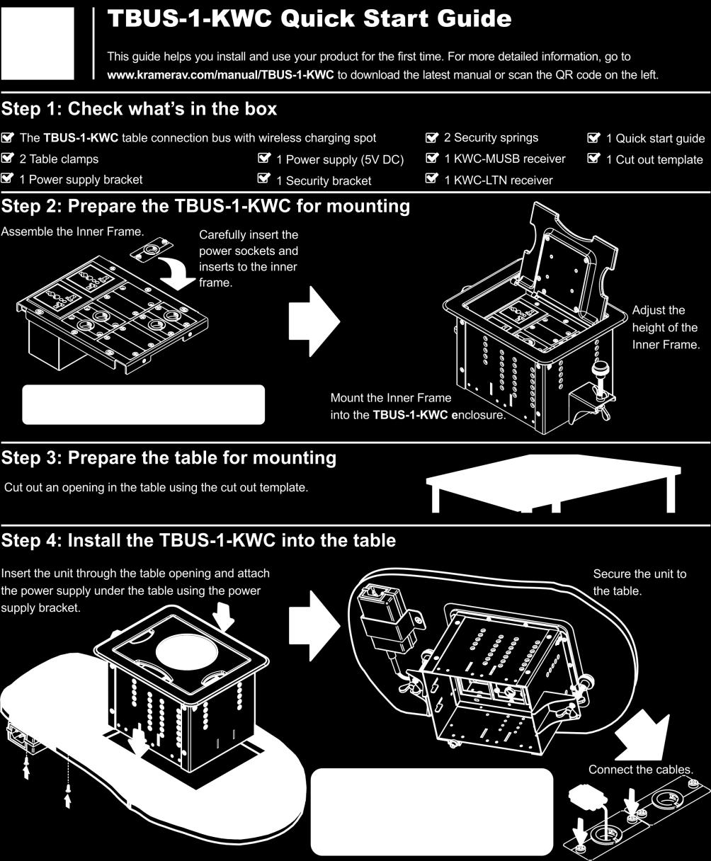
15 5 Installing the TBUS-1-KWC To install the TBUS-1-KWC: 1. Assemble the inner frame (see Section 5.1). 2. Install the inner frame (see Section 5.2). 3. Cut an opening in the table (see Section 5.3). 4. Insert the unit through the opening and secure it to the table (see Section 5.4). 5. Connect the cables (see Section 5.5). 6. Insert the pass-through cables (see Section 5.6). 7. Adjust the height of the inner frame (see Section 5.7). 5.1 Assembling the Inner Frame The modules mounted on the inner frame can include single inserts and/or dual inserts as well as power sockets and various Kramer devices. This section describes how to assemble these modules. Each module kit is supplied with detailed assembly instructions Mounting the Inserts You can rearrange or remove any of the plates mounted on the inner frame and replace them with Kramer passive wall plates or connector modules for interfacing A/V type signals. To mount a Kramer insert or connector module: 1. Unscrew the two screws that fasten the blank plate to the inner frame and remove the blank plate. 2. Place the required Kramer insert over the opening, insert the two screws to fix the Kramer insert in place, and tighten them. 12 TBUS-1-KWC - Installing the TBUS-1-KWC

16 Figure 4: TBUS-1-KWC Inner Frame (P/N: ) # Feature Function 1 Split Brackets Support the split grommet for the pass through-cables 2 Split Grommets Push apart slightly to insert cables 3 Blank Plates Four blank covers that can be replaced with wall plates as required 4 Power Socket Opening Suitable for a single power socket or the T-2INSERT 5 Adjustable Height Screw Holes For adjusting the height of the inner frame Mounting the Power Socket Assemblies To mount the power socket, place the power socket under the frame in its appropriate place and tighten with the two screws (supplied). Power socket kits are supplied with assembly instructions. TBUS-1-KWC - Installing the TBUS-1-KWC 13
17 5.1.3 Mounting a Kramer TOOL To mount a TOOL (for example, to the T1AF-14T), as shown in Figure 5: 1. Screw the spacers to their designated places (one on each side). 2. Insert the TOOL, from beneath, through the TOOL opening. 3. Screw the screws (one on each side) through the frame holes and spacers. Figure 5: Installing a Kramer TOOL 14 TBUS-1-KWC - Installing the TBUS-1-KWC
18 5.1.4 Installing the TOOL Blank To install the T-TBLANK, as shown in Figure 6: 1. Insert the T-TBLANK from beneath, through the TOOL opening. 2. Screw the screws (one on each side) through the frame. Figure 6: Installing the T-TBLANK TOOL Blank TBUS-1-KWC - Installing the TBUS-1-KWC 15

.")
19 5.1.5 Mounting the Special Panel for RC-8IR The Kramer T-RC8IR for the TBUS-1-KWC Table Connection bus is used to fit the Kramer RC-8IR Control Panel into the appropriate frame (P/N or P/N instead of two power sockets). Figure 7: T-RC8IR (P/N: ) 16 TBUS-1-KWC - Installing the TBUS-1-KWC

20 To replace the RC-8IR faceplate: 1. Unscrew the two faceplate attachment screws and remove the RC-8IR faceplate before installing the T-RC8IR. Figure 8: RC-8IR Faceplate Holes Table Connection Bus 2. Place the T-RC8IR over the RC-8IR enclosure so that both face plate holes are aligned with the face plate holes on the RC-8IR enclosure and the IR IN receiver fits into the IR IN opening. 3. Insert the faceplate screws through the T-RC8IR and RC-8IR enclosure faceplate holes, and tighten. To install the T-RC8IR: 1. Insert the T-RC8IR assembly through the dual power socket opening from beneath. 2. Use the two power socket screws to tighten the T-RC8IR assembly in place Installing the SI-1VGA / RC-3TB To install the SI-1VGA / RC-3TB module, place it under the designated opening in the T1AF-14L (P/N: ) and then screw and tighten it in place using the two screws supplied with the inner frame. TBUS-1-KWC - Installing the TBUS-1-KWC 17
21 5.2 Installing the Inner Frame To install the inner frame: 1. Place the inner frame inside the TBUS-1-KWC enclosure. 2. Set the required height using your fingers to bring the inner frame to the desired position, screw and tighten it in place using the height adjustment screws (supplied with the inner frame). Inner frame kits come with assembly instructions. 5.3 Cutting an Opening in the Table To cut an opening in the table: 1. Place the included cut out template (that is included with your TBUS-1-KWC) on the surface of the table exactly where you want to install the TBUS-1-KWC. 2. Attach the template to the table with the included screws (if using the cut out template). 3. Following the inside edge of the template, cut a hole in the table surface with a sabre or keyhole saw according to the dimensions shown in Figure 9 (not to scale). The thickness of the table should be 76 mm / 3 inches or less. Figure 9: Cut Out Dimensions 18 TBUS-1-KWC - Installing the TBUS-1-KWC
22 4. Unscrew and remove the template from the surface of the table and clean the table surface. Take care not to damage the table. If needed, you can download a full-scale template from our Web site. Kramer Electronics is not responsible for any damage caused to the table. 5.4 Inserting the TBUS-1-KWC through the Cut Out Opening To install TBUS-1-KWC in the opening: 1. Remove the protective rubber guard from around the outer rim of the TBUS-1-KWC housing. Beware of the sharp edge! 2. Carefully insert the unit into the prepared opening (see Figure 10). 3. Attach the power supply under the table using the power supply bracket (supplied with the package). 4. Take the support brackets under the table and place them into the support bracket grooves on both sides of the unit (see Figure 2, item 6). 5. Verify proper alignment of the unit before tightening the mounting screws. 6. Tighten both mounting butterfly screws upward until they reach the table surface (from underneath). Tighten firmly (see Figure 10). 7. Tighten the locking butterfly screws downward until tight against the mounting bracket. TBUS-1-KWC - Installing the TBUS-1-KWC 19
.")

23 Figure 10: Inserting TBUS-1-KWC into the Prepared Opening 5.5 Connecting the Cables Connect the Charging spot to the power supply and the power supply to the mains electricity (the power cord is purchased separately, see Section 4.3). To connect the cables when replacing blank inserts with connector inserts (for example, VGA, audio, HDMI and so on): 1. Insert the cables to their appropriate connectors from underneath. 2. Secure the cables to the tie holes on the TBUS-1-KWC. Do not secure the cables too tightly or too loosely. Leave a small amount of slack. 5.6 Inserting the Pass-through Cables To insert the pass through cables (for example, to connect a laptop): 1. Remove the two screws attaching the split pass-through bracket. 2. Remove the split grommet. 3. Insert the cable through the rectangular opening. 4. Open the split grommet slightly and insert the required cables. 20 TBUS-1-KWC - Installing the TBUS-1-KWC


24 5. Place the split bracket around the grommet and position this assembly over the inner frame. 6. Place the two screws appropriately and tighten the split bracket together with the grommet and inserted cables to the inner frame. 7. Insert the self-locking ties through the tie holes to secure the cables to the inside walls of the enclosure. Figure 11: Cable Pass-through Insert (P/N: ) 5.7 Adjusting the Height of the Inner Frame If needed, you can adjust the inner frame height to accommodate large or bulky cables. To adjust the inner frame height: 1. Remove the height adjustment screws, while supporting the surface from underneath with your fingers. 2. Raise or lower the inner frame to the required height, insert the screws, and tighten them in place. TBUS-1-KWC - Installing the TBUS-1-KWC 21

25 6 Using the TBUS-1-KWC Once the TBUS-1-KWC is installed, you can easily customize it to suit your own requirements by plugging in the required A/V equipment, as illustrated in the example in Figure 12. Figure 12: TBUS-1-KWC Boardroom Installation 6.1 Using the Wireless Charger To use the Kramer Wireless charger on the lid: 1. Make sure that the charging spot power cable is connected. 2. If your mobile device supports wireless charging, place it on the charging spot until it is fully charged. If your mobile device does not support wireless charging, you can connect it to either the KWC-MUSB Micro USB receiver or the KWC-LTN lightning receiver (see Section 6.2), supplied with the package. Additional receivers can be purchased separately. Note that you can only charge one mobile device at a time. 22 TBUS-1-KWC - Using the TBUS-1-KWC
 products. These receivers are used for mobile devices that DO NOT have a built-in wireless charging receiver.")
26 6.2 Using the Receivers The Kramer KWC-MUSB and KWC-LTN wireless charging receivers (one of each is supplied with the TBUS-1-KWC). These receivers can be used with Kramer Wireless Charging (KWC) products. These receivers are used for mobile devices that DO NOT have a built-in wireless charging receiver. Mobile devices with a built-in wireless receiver, compliant with the Qi standard, can be placed directly on the charging spot. The KWC-MUSB Micro USB receiver (see Figure 13) and KWC-LTN lightning receiver (see Figure 14) are wireless power receivers that utilize electromagnetic induction to charge mobile devices wirelessly and are compatible with the Qi standard for wireless chargers (with security eyeholes). Figure 13: KWC-MUSB Micro USB Receiver Figure 14: KWC-LTN Lightning Receiver Figure 15: Receiver Underside Additional receivers can be purchased separately. TBUS-1-KWC - Using the TBUS-1-KWC 23
 until it s fully charged.")
27 6.3 Using the Wireless Charger To use the Kramer receivers: 1. Connect your mobile device to either the KWC-MUSB Micro USB receiver or the KWC-LTN lightning receiver, as required. 2. Place the mobile device with the attached receiver centered on the charging spot (correct side facing the charging spot, see Figure 15) until it s fully charged. You can only charge one mobile device via the charging spot at a time. When charging a mobile device, do not place any metal or magnetic objects over the receiver. Charging a mobile device using the receiver in the vicinity of pacemakers, hearing aids, or similar medical electronic devices may interfere with the function of these devices. Make sure the receivers are used in a cool and well-ventilated environment and away from flammable and explosive objects. Avoid using the receivers in extreme temperatures or high humidity. 6.4 Securing Wireless Charging Receivers Use the security springs and bracket (included) to secure the wireless charging receivers to the TBUS-1-KWC. To secure the wireless charging receivers: 1. Thread the security spring loop through the eyehole on the security bracket. 2. Pull the loop on the other side of the spring through the threaded loop. Figure 16: Connecting to the Security Bracket 24 TBUS-1-KWC - Using the TBUS-1-KWC


. 5.")
28 3. Thread the free loop through the security eyehole on the wireless charging receiver. Figure 17: Threading the Loop through the Receiver Eyehole 4. Pull the security bracket through the threaded loop, so that the bracket is looped on one side and the receiver on the other side. Figure 18: Security Spring with Bracket and Receiver You can attach one or more wireless receivers in the same way (by passing all the springs through the loop in step 4). 5. Mount the security bracket onto the inner frame (see Section 5.1.1). TBUS-1-KWC - Using the TBUS-1-KWC 25
29 7 Technical Specifications of the TBUS-1-KWC POWER SOURCE (AC power limits): FUSE RATING: Single Socket Assemblies: Universal Maximum 5A per power outlet Fully compatible with power plugs in the UK, India, Italy and Denmark, as well as with the 2-prong Europlug. Partially compatible (if the polarity is reversed) with plugs in China, Switzerland, Israel and the USA. The universal socket does not supply grounding to plugs in Central Europe and France (you should order country specific sockets instead). Not compatible with South African plugs. USA Germany and EU Belgium and France Italy Australia Israel South Africa Switzerland UK Brazil Dual Power Kit Assemblies: Universal USA Belgium and France Germany and EU Italy Israel Switzerland UK Australia South Africa T 6.3A 250V Maximum 5A per power outlet Maximum 5A per power outlet Maximum 5A per power outlet Maximum 5A per power outlet Maximum 5A per power outlet 220V AC, 50/60Hz, 5A Maximum 5A per power outlet Maximum 5A per power outlet Maximum 5A per power outlet Maximum 5A per power outlet 220V AC, 50/60Hz, 5A Maximum 5A per power outlet Maximum 5A per power outlet Maximum 5A per power outlet Maximum 5A per power outlet 26 TBUS-1-KWC - Technical Specifications of the TBUS-1-KWC
30 POWER CONSUMPTION: CHARGING EFFICIENCY: 70% CHARGING POWER OUTPUT: SAFETY REGULATORY COMPLIANCE: STANDARD: OPERATING TEMPERATURE RANGE: OPERATING HUMIDITY RANGE: STORAGE TEMPERATURE RANGE: STORAGE HUMIDITY RANGE: DIMENSIONS: WEIGHT: Charging spot: 5V DC, 1A 700 ma Max CE, FCC Qi +5 to +45 Deg. Centigrade 10 to 90% RHL, non-condensing -20 to +70 Deg. Centigrade 5 to 95% RHL, non-condensing 22.1cm x 18.2cm x 13cm (8.17" x 5.88" x 5.13") W, D, H Gross weight: 2.3kg (5.07lbs) approx. TBUS-1-KWC with table clamps: 1.75kg (3.6lbs) approx.; Metal template: 0.125kg (0.28lbs) approx. ACCESSORIES: Power cord, six self-locking ties, metal template, 1 KWC-MUSB, 1 KWC-LTN (see separate specifications in Section 7.1), 1 security bracket, 2 security springs, power supply, power supply bracket OPTIONS: Specifications are subject to change without notice at Inner frames, passive wall plates and interfaces, power socket kits, power supply, bracket for power supply 7.1 Technical Specifications of the KWC-MUSB and KWC-LTN PORT: LED INDICATORS: CHARGING EFFICIENCY: 70% CHARGING POWER: STANDARD: SAFETY REGULATORY COMPLIANCE: OPERATING TEMPERATURE: STORAGE TEMPERATURE: HUMIDITY: DIMENSIONS: WEIGHT: COLORS: KWC-MUSB: micro USB receiver KWC-LTN: lightning receiver ON (blue) 5V DC, 700 ma Max Qi CE, FCC 0 to +40 C (32 to 104 F) -40 to +70 C (-40 to 158 F) 10% to 90%, RHL non-condensing 3.7cm x 5cm x 0.85cm (17.2 x 7.2 x 1.7 ) W, D, H Net: 0.012kg (0.03lb) Gross: 0.032kg (0.07lb) KWC-MUSB: light blue KWC-LTN: light green Specifications are subject to change without notice at TBUS-1-KWC - Technical Specifications of the TBUS-1-KWC 27

31

32 P/N: Rev: 7 SAFETY WARNING Disconnect the unit from the power supply before opening and servicing For the latest information on our products and a list of Kramer distributors, visit our Web site where updates to this user manual may be found. We welcome your questions, comments, and feedback. info@kramerav.com
USER MANUAL MODEL: KWC-1 Wireless Charging Spot
 USER MANUAL MODEL: KWC-1 Wireless Charging Spot P/N: 2900-300504 Rev 6 www.kramerav.com Contents 1 Introduction 1 2 Getting Started 2 2.1 Achieving the Best Performance 2 2.2 Recycling Kramer Products
Kramer Electronics, Ltd. USER MANUAL. Model: TBUS-9. Table Connection Bus
 Kramer Electronics, Ltd. USER MANUAL Model: TBUS-9 Table Connection Bus Contents Contents 1 Introduction 1 2 Getting Started 1 2.1 Quick Start 2 3 Overview 3 4 Your TBUS-9 4 5 Installing the TBUS-9 Table
USER MANUAL MODEL: TDPB-2V1AD Dual square table box with HDMI, VGA, 3.5mm audio, and RJ45 inputs
 USER MANUAL MODEL: TDPB-2V1AD Dual square table box with HDMI, VGA, 3.5mm audio, and RJ45 inputs Contents 1 Introduction 1 2 Getting Started 2 2.1 Achieving the Best Performance 2 2.2 Recycling Products
PCS88-90 (Black) PCS88-94 (Silver)
 PCS88-94 (Silver)") USER MANUAL MODELS: PCS88-90 (Black) PCS88-94 (Silver) Pop-up Table Connection Bus Contents 1 Introduction 1 2 Getting Started 2 2.1 Achieving the Best Performance 2 2.2 Recycling Products 2 3 Overview
USER MANUAL MODELS: PCS88-90 (Black) PCS88-94 (Silver) Pop-up Table Connection Bus Contents 1 Introduction 1 2 Getting Started 2 2.1 Achieving the Best Performance 2 2.2 Recycling Products 2 3 Overview
USER MANUAL. PT-101UHD HDMI Repeater MODEL: P/N: Rev 3.
 USER MANUAL MODEL: PT-101UHD HDMI Repeater P/N: 2900-300492 Rev 3 www.kramerav.com Contents 1 Introduction 1 2 Getting Started 2 2.1 Achieving the Best Performance 2 2.2 Safety Instructions 2 2.3 Recycling
USER MANUAL. RC-43T Remote Controller MODEL: P/N: Rev 3
 KRAMER ELECTRONICS LTD. USER MANUAL MODEL: RC-43T Remote Controller P/N: 2900-300301 Rev 3 Contents 1 Introduction 1 2 Getting Started 2 2.1 Achieving the Best Performance 2 2.2 Safety Instructions 3
USER MANUAL. RC-43SL 6-Button Room Controller MODEL: P/N: Rev 1.
 USER MANUAL MODEL: RC-43SL 6-Button Room Controller P/N: 2900-300450 Rev 1 www.kramerav.com Contents 1 Introduction 1 2 Getting Started 2 2.1 Achieving the Best Performance 2 2.2 Safety Instructions
USER MANUAL. PT-1C EDID Processor MODEL: P/N: Rev 3
 KRAMER ELECTRONICS LTD. USER MANUAL MODEL: PT-1C EDID Processor P/N: 2900-300276 Rev 3 Contents 1 Introduction 1 2 Getting Started 2 2.1 Achieving the Best Performance 2 2.2 Recycling Kramer Products
USER MANUAL. RC-43SL 6-Button Room Controller MODEL: P/N: Rev 3.
 USER MANUAL MODEL: RC-43SL 6-Button Room Controller P/N: 2900-300450 Rev 3 www.kramerav.com Contents 1 Introduction 1 2 Getting Started 2 2.1 Achieving the Best Performance 2 2.2 Safety Instructions
USER MANUAL. PT-5T/R IR Extender/Repeater MODEL: P/N: Rev 3
 KRAMER ELECTRONICS LTD. USER MANUAL MODEL: PT-5T/R IR Extender/Repeater P/N: 2900-300010 Rev 3 Contents 1 Introduction 1 2 Getting Started 2 2.1 Achieving the Best Performance 2 2.2 Safety Instructions
USER MANUAL RC-76M/RC-712M MODEL: P/N: Rev 3
 KRAMER ELECTRONICS LTD. USER MANUAL MODEL: RC-76M/RC-712M P/N: 2900-300329 Rev 3 Contents 1 Introduction 1 2 Getting Started 2 2.1 Achieving the Best Performance 2 2.2 Safety Instructions 3 2.3 Recycling
KRAMER ELECTRONICS LTD. USER MANUAL MODEL: RC-76R/RC-78R Room Controllers. P/N: Rev 5
 KRAMER ELECTRONICS LTD. USER MANUAL MODEL: RC-76R/RC-78R Room Controllers P/N: 2900-300253 Rev 5 Contents 1 Introduction 1 2 Getting Started 2 2.1 Achieving the Best Performance 2 2.2 Safety Instructions
USER MANUAL. VM-2Hxl 1:2 HDMI Distributor MODEL: P/N: Rev 3
 KRAMER ELECTRONICS LTD. USER MANUAL MODEL: VM-2Hxl 1:2 HDMI Distributor P/N: 2900-000672 Rev 3 Contents 1 Introduction 1 2 Getting Started 2 2.1 Achieving the Best Performance 2 2.2 Safety Instructions
USER MANUAL. RS-232 Extender MODEL: P/N: Rev 1
 USER MANUAL MODEL: RS-232 Extender P/N: 2900-300284 Rev 1 Contents 1 Introduction 1 2 Getting Started 2 2.1 Achieving the Best Performance 2 2.2 Safety Instructions 3 2.3 Recycling Kramer Products 3 3
KRAMER ELECTRONICS LTD. USER MANUAL MODEL: VS-41HC 4x1 HDMI Switcher. P/N: Rev 4
 KRAMER ELECTRONICS LTD. USER MANUAL MODEL: VS-41HC 4x1 HDMI Switcher P/N: 2900-000423 Rev 4 Contents 1 Introduction 1 2 Getting Started 2 2.1 Achieving the Best Performance 2 2.2 Safety Instructions 3
USER MANUAL. 671T DVI Optical Transmitter. 671R DVI Optical Receiver MODEL: P/N: Rev 4
 KRAMER ELECTRONICS LTD. USER MANUAL MODEL: 671T DVI Optical Transmitter 671R DVI Optical Receiver P/N: 2900-000484 Rev 4 Contents 1 Introduction 1 2 Getting Started 2 2.1 Achieving the Best Performance
USER MANUAL. RC-76R/RC-78R Room Controllers MODEL: P/N: Rev 2
 KRAMER ELECTRONICS LTD. USER MANUAL MODEL: RC-76R/RC-78R Room Controllers P/N: 2900-300253 Rev 2 Contents 1 Introduction 1 2 Getting Started 2 2.1 Achieving the Best Performance 2 2.2 Safety Instructions
USER MANUAL. RC-74DL Master Room Controller MODEL: P/N: Rev 4
 KRAMER ELECTRONICS LTD. USER MANUAL MODEL: RC-74DL Master Room Controller P/N: 2900-000691 Rev 4 Contents 1 Introduction 1 2 Getting Started 2 2.1 Achieving the Best Performance 2 2.2 Safety Instructions
USER MANUAL. SL-1N Master Room Controller MODEL: P/N: Rev 1
 KRAMER ELECTRONICS LTD. USER MANUAL MODEL: SL-1N Master Room Controller P/N: 2900-300399 Rev 1 Contents 1 Introduction 1 2 Getting Started 2 2.1 Achieving the Best Performance 2 2.2 Safety Instructions
USER MANUAL. 602T Two-fiber Detachable Optical DVI Transmitter 602R. DVI Receiver MODELS: P/N: Rev 3
 KRAMER ELECTRONICS LTD. USER MANUAL MODELS: 602T Two-fiber Detachable Optical DVI Transmitter 602R Two-fiber Detachable Optical DVI Receiver P/N: 2900-000646 Rev 3 Contents 1 Introduction 1 2 Getting
USER MANUAL. VM-2HDCPxl 1:2 DVI Distributor MODEL: P/N: Rev 3
 KRAMER ELECTRONICS LTD. USER MANUAL MODEL: VM-2HDCPxl 1:2 DVI Distributor P/N: 2900-000510 Rev 3 Contents 1 Introduction 1 2 Getting Started 2 2.1 Achieving the Best Performance 2 2.2 Safety Instructions
USER MANUAL. 614T One-Fiber Detachable Optical DVI Transmitter. 614R One-Fiber Detachable Optical DVI Receiver MODELS: P/N: Rev 5
 KRAMER ELECTRONICS LTD. USER MANUAL MODELS: 614T One-Fiber Detachable Optical DVI Transmitter 614R One-Fiber Detachable Optical DVI Receiver P/N: 2900-300249 Rev 5 Contents 1 Introduction 1 2 Getting
USER MANUAL. VP-211K Automatic UXGA / Audio Switcher MODEL: P/N: Rev 3
 KRAMER ELECTRONICS LTD. USER MANUAL MODEL: VP-211K Automatic UXGA / Audio Switcher P/N: 2900-000414 Rev 3 Contents 1 Introduction 1 2 Getting Started 2 2.1 Achieving the Best Performance 2 2.2 Safety
KRAMER ELECTRONICS LTD. USER MANUAL MODEL: RC-74DL Master Room Controller. P/N: Rev 5
 KRAMER ELECTRONICS LTD. USER MANUAL MODEL: RC-74DL Master Room Controller P/N: 2900-000691 Rev 5 Contents 1 Introduction 1 2 Getting Started 2 2.1 Achieving the Best Performance 2 2.2 Safety Instructions
KRAMER ELECTRONICS LTD. USER MANUAL MODEL: VA-1VGAN EDID Capture. P/N: Rev 2
 KRAMER ELECTRONICS LTD. USER MANUAL MODEL: VA-1VGAN EDID Capture P/N: 2900-000513 Rev 2 Contents 1 Introduction 1 2 Getting Started 2 2.1 Achieving the Best Performance 2 2.2 Recycling Kramer Products
KRAMER ELECTRONICS LTD. USER MANUAL MODEL: VS-211HA Automatic HDMI Standby Switcher. P/N: Rev 3
 KRAMER ELECTRONICS LTD. USER MANUAL MODEL: VS-211HA Automatic HDMI Standby Switcher P/N: 2900-300378 Rev 3 Contents 1 Introduction 1 2 Getting Started 2 2.1 Achieving the Best Performance 2 2.2 Safety
Kramer Electronics, Ltd. USER MANUAL. Models: VM-8H, 1:8 HDMI Distributor VM-16H, 1:16 HDMI Distributor
 Kramer Electronics, Ltd. USER MANUAL Models: VM-8H, 1:8 HDMI Distributor VM-16H, 1:16 HDMI Distributor Contents Contents 1 Introduction 1 2 Getting Started 1 2.1 Quick Start 2 3 Overview 3 3.1 Recommendations
USER MANUAL V/100V Power Amplifier MODEL: P/N: Rev 4
 KRAMER ELECTRONICS LTD. USER MANUAL MODEL: 920 70V/100V Power Amplifier P/N: 2900-300308 Rev 4 Contents 1 Introduction 1 2 Getting Started 2 2.1 Achieving the Best Performance 2 2.2 Safety Instructions
USER MANUAL. SL-10 Master Room Controller MODEL: P/N: Rev 4
 KRAMER ELECTRONICS LTD. USER MANUAL MODEL: SL-10 Master Room Controller P/N: 2900-000581 Rev 4 Contents 1 Introduction 1 2 Getting Started 2 2.1 Achieving the Best Performance 2 2.2 Safety Instructions
USER MANUAL. VA-1USB-T USB Transmitter. VA-1USB-R USB Receiver MODELS: P/N: Rev 3
 KRAMER ELECTRONICS LTD. USER MANUAL MODELS: VA-1USB-T USB Transmitter VA-1USB-R USB Receiver P/N: 2900-300209 Rev 3 Contents 1 Introduction 1 2 Getting Started 2 2.1 Achieving the Best Performance 2 2.2
KRAMER ELECTRONICS LTD. USER MANUAL MODEL: VM-73 Multiformat 1:3 Distribution Amplifier. P/N: Rev 3
 KRAMER ELECTRONICS LTD. USER MANUAL MODEL: VM-73 Multiformat 1:3 Distribution Amplifier P/N: 2900-000544 Rev 3 Contents 1 Introduction 1 2 Getting Started 2 2.1 Achieving the Best Performance 2 2.2 Recycling
KRAMER ELECTRONICS LTD. USER MANUAL MODEL: 622T Dual Link DVI Optical Transmitter. 622R Dual Link DVI Optical Receiver. P/N: Rev 4
 KRAMER ELECTRONICS LTD. USER MANUAL MODEL: 622T Dual Link DVI Optical Transmitter 622R Dual Link DVI Optical Receiver P/N: 2900-000104 Rev 4 Contents 1 Introduction 1 2 Getting Started 2 2.1 Achieving
KRAMER ELECTRONICS LTD. USER MANUAL MODEL: VM-24H 2 Input 1:4 HDMI Distributor. P/N: Rev 4
 KRAMER ELECTRONICS LTD. USER MANUAL MODEL: VM-24H 2 Input 1:4 HDMI Distributor P/N: 2900-000664 Rev 4 Contents 1 Introduction 1 2 Getting Started 2 2.1 Achieving the Best Performance 2 2.2 Safety Instructions
USER MANUAL. PT-580T HDMI Line Transmitter. TP-580T HDMI Line Transmitter. TP-580R HDMI Line Receiver MODELS: P/N: Rev 3
 KRAMER ELECTRONICS LTD. USER MANUAL MODELS: PT-580T HDMI Line Transmitter TP-580T HDMI Line Transmitter TP-580R HDMI Line Receiver P/N: 2900-300340 Rev 3 Contents 1 Introduction 1 2 Getting Started 2
USER MANUAL. 621T DVI Optical Transmitter. 621R DVI Optical Receiver MODEL: P/N: Rev 8
 KRAMER ELECTRONICS LTD. USER MANUAL MODEL: 621T DVI Optical Transmitter 621R DVI Optical Receiver P/N: 2900-000103 Rev 8 Contents 1 Introduction 1 2 Getting Started 2 2.1 Achieving the Best Performance
USER MANUAL. RC-54DL KNET Auxiliary Control Panel MODEL: P/N: Rev 2
 KRAMER ELECTRONICS LTD. USER MANUAL MODEL: RC-54DL KNET Auxiliary Control Panel P/N: 2900-300130 Rev 2 Contents 1 Introduction 1 2 Getting Started 2 2.1 Achieving the Best Performance 2 3 Overview 3 3.1
USER MANUAL. VM-28H 2 Input 1:8 HDMI Distributor. VM-216H 2 Input 1:16 HDMI Distributor MODEL: P/N: Rev 5
 KRAMER ELECTRONICS LTD. USER MANUAL MODEL: VM-28H 2 Input 1:8 HDMI Distributor VM-216H 2 Input 1:16 HDMI Distributor P/N: 2900-000662 Rev 5 Contents 1 Introduction 1 2 Getting Started 2 2.1 Achieving
KRAMER ELECTRONICS LTD. USER MANUAL MODELS: TP-125xl UXGA/Audio/Data Line Transmitter. TP-126xl UXGA/Audio/Data Line Receiver. P/N: Rev 4
 KRAMER ELECTRONICS LTD. USER MANUAL MODELS: TP-125xl UXGA/Audio/Data Line Transmitter TP-126xl UXGA/Audio/Data Line Receiver P/N: 2900-300206 Rev 4 Contents 1 Introduction 1 2 Getting Started 2 2.1 Achieving
USER MANUAL. TP-780T HDMI Line Transmitter + POE TP-780R HDMI Line Receiver + POE MODELS: P/N: Rev 2.
 USER MANUAL MODELS: TP-780T HDMI Line Transmitter + POE TP-780R HDMI Line Receiver + POE P/N: 2900-300575 Rev 2 www.kramerav.com Contents 1 Introduction 1 2 Getting Started 2 2.1 Achieving the Best Performance
USER MANUAL. VP-311DVI Automatic DVI/Audio Switcher MODEL: P/N: Rev 3
 KRAMER ELECTRONICS LTD. USER MANUAL MODEL: VP-311DVI Automatic DVI/Audio Switcher P/N: 2900-000120 Rev 3 Contents 1 Introduction 1 2 Getting Started 2 2.1 Achieving the Best Performance 2 2.2 Safety Instructions
USER MANUAL. VS Port RS-422 Matrix Switcher MODEL: P/N: Rev 5
 KRAMER ELECTRONICS LTD. USER MANUAL MODEL: VS-4228 8-Port RS-422 Matrix Switcher P/N: 2900-0033 Rev 5 Contents 1 Introduction 1 2 Getting Started 2 2.1 Achieving the Best Performance 2 2.2 Safety Instructions
USER MANUAL. TP-580Txr HDMI Line Transmitter. TP-580Rxr HDMI Line Receiver MODELS: P/N: Rev 5
 KRAMER ELECTRONICS LTD. USER MANUAL MODELS: TP-580Txr HDMI Line Transmitter TP-580Rxr HDMI Line Receiver P/N: 2900-300088 Rev 5 Contents 1 Introduction 1 2 Getting Started 2 2.1 Achieving the Best Performance
KRAMER ELECTRONICS LTD. USER MANUAL MODELS: WP-110, XGA Line Transmitter. PT-120, XGA Line Receiver. TP-120, XGA Line Receiver. P/N: Rev 1
 KRAMER ELECTRONICS LTD. USER MANUAL MODELS: WP-110, XGA Line Transmitter PT-120, XGA Line Receiver TP-120, XGA Line Receiver P/N: 2900-300180 Rev 1 Contents 1 Introduction 1 2 Getting Started 2 2.1 Achieving
WAV-5 WAV-5C WAV-3 WA-1H WAV-1R WAV-1RP
 KRAMER ELECTRONICS LTD. USER MANUAL MODELS: WAV-5 WAV-5C WAV-3 WA-1H WAV-1R WAV-1RP Wall Plate Series P/N: 2900-300124 Rev 2 Contents 1 Introduction 1 2 Getting Started 2 2.1 Achieving the Best Performance
USER MANUAL. VS-311H Automatic HDMI/Audio Switcher MODEL: P/N: Rev 3
 KRAMER ELECTRONICS LTD. USER MANUAL MODEL: VS-311H Automatic HDMI/Audio Switcher P/N: 2900-000666 Rev 3 Contents 1 Introduction 1 2 Getting Started 2 2.1 Achieving the Best Performance 2 2.2 Safety Instructions
KRAMER ELECTRONICS LTD. USER MANUAL MODELS: TP-580T HDMI Line Transmitter. TP-580R HDMI Line Receiver. P/N: Rev 2
 KRAMER ELECTRONICS LTD. USER MANUAL MODELS: TP-580T HDMI Line Transmitter TP-580R HDMI Line Receiver P/N: 2900-300034 Rev 2 Contents 1 Introduction 1 2 Getting Started 2 2.1 Achieving the Best Performance
KRAMER ELECTRONICS LTD. USER MANUAL MODEL: 905xl Power Amplifier. P/N: Rev 3
 KRAMER ELECTRONICS LTD. USER MANUAL MODEL: 905xl Power Amplifier P/N: 2900-300196 Rev 3 Contents 1 Introduction 1 2 Getting Started 2 2.1 Achieving the Best Performance 2 2.2 Safety Instructions 2 2.3
USER MANUAL. TP-145 XGA/Audio/Data Line Transmitter. TP-146 UXGA/Audio/Data Line Receiver MODELS: P/N: Rev 3
 KRAMER ELECTRONICS LTD. USER MANUAL MODELS: TP-145 XGA/Audio/Data Line Transmitter TP-146 UXGA/Audio/Data Line Receiver P/N: 2900-000607 Rev 3 Contents 1 Introduction 1 2 Getting Started 2 2.1 Achieving
KRAMER ELECTRONICS LTD. USER MANUAL MODEL: VS-41H 4x1 HDMI Switcher. P/N: Rev 7
 KRAMER ELECTRONICS LTD. USER MANUAL MODEL: VS-41H 4x1 HDMI Switcher P/N: 2900-000667 Rev 7 Contents 1 Introduction 1 2 Getting Started 2 2.1 Achieving the Best Performance 2 2.2 Safety Instructions 3
USER MANUAL. TP-780TXR Extended Range HDMI Line Transmitter + POE TP-780RXR Extended Range HDMI Line Receiver + POE MODELS: P/N: Rev 2
 USER MANUAL MODELS: TP-780TXR Extended Range HDMI Line Transmitter + POE TP-780RXR Extended Range HDMI Line Receiver + POE P/N: 2900-300576 Rev 2 www.kramerav.com Contents 1 Introduction 1 2 Getting
USER MANUAL. KT-10 Touch Panel MODEL: P/N: Rev 1.
 USER MANUAL MODEL: KT-10 Touch Panel P/N: 2900-300607 Rev 1 www.kramerav.com Contents 1 Introduction 1 2 Getting Started 2 2.1 Achieving the Best Performance 2 2.2 Safety Instructions 2 2.3 Recycling
Kramer Electronics, Ltd.
 Kramer Electronics, Ltd. Preliminary USER MANUAL Model: FC-50 RS-232 Range Extender Contents Contents 1 Introduction 1 2 Getting Started 1 2.1 Quick Start 2 3 Overview 3 3.1 About the Power Connect Feature
USER MANUAL. VS-21HDCP-IR 2x1 DVI Switcher MODEL: P/N: Rev 5
 KRAMER ELECTRONICS LTD. USER MANUAL MODEL: VS-21HDCP-IR 2x1 DVI Switcher P/N: 2900-000556 Rev 5 Contents 1 Introduction 1 2 Getting Started 2 2.1 Achieving the Best Performance 2 2.2 Safety Instructions
USER MANUAL. VS-88H 8x8 HDMI Matrix Switcher MODEL: P/N: Rev 5
 KRAMER ELECTRONICS LTD. USER MANUAL MODEL: VS-88H 8x8 HDMI Matrix Switcher P/N: 2900-000654 Rev 5 Contents 1 Introduction 1 2 Getting Started 2 2.1 Achieving the Best Performance 2 2.2 Safety Instructions
USER MANUAL VM-4HN 1:4 HDMI DA MODEL: P/N: Rev 4
 KRAMER ELECTRONICS LTD. USER MANUAL MODEL: VM-4HN 1:4 HDMI DA P/N: 2900-300106 Rev 4 Contents 1 Introduction 1 2 Getting Started 2 2.1 Achieving the Best Performance 2 2.2 Safety Instructions 3 2.3 Recycling
USER MANUAL VM-2HN 1:2 HDMI DA MODEL: P/N: Rev 3
 KRAMER ELECTRONICS LTD. USER MANUAL MODEL: VM-2HN 1:2 HDMI DA P/N: 2900-300381 Rev 3 Contents 1 Introduction 1 2 Getting Started 2 2.1 Achieving the Best Performance 2 2.2 Safety Instructions 3 2.3 Recycling
KRAMER ELECTRONICS LTD. USER MANUAL MODEL: VA-1VGAxl EDID Capture/Emulator. P/N: Rev 2
 KRAMER ELECTRONICS LTD. USER MANUAL MODEL: VA-1VGAxl EDID Capture/Emulator P/N: 2900-300011 Rev 2 Contents 1 Introduction 1 2 Getting Started 2 2.1 Achieving the Best Performance 2 3 Overview 3 3.1 Defining
KRAMER ELECTRONICS LTD. USER MANUAL MODELS: TP-121EDID, XGA /Audio Line Transmitter TP-125EDID, XGA. PT-110EDID, XGA Line Transmitter
 KRAMER ELECTRONICS LTD. USER MANUAL MODELS: TP-121EDID, XGA /Audio Line Transmitter TP-123EDID, XGA /Audio/Data Line Transmitter TP-125EDID, XGA /Audio/Data Line Transmitter PT-110EDID, XGA Line Transmitter
KRAMER ELECTRONICS LTD. USER MANUAL MODEL: VS-401USB 4x1 USB Switcher. P/N: Rev 1
 KRAMER ELECTRONICS LTD. USER MANUAL MODEL: VS-401USB 4x1 USB Switcher P/N: 2900-300029 Rev 1 Contents 1 Introduction 1 2 Getting Started 2 2.1 Achieving the Best Performance 2 2.2 Recycling Kramer Products
USER MANUAL. TP-780TXR Extended Range HDMI Line Transmitter + POE TP-780RXR Extended Range HDMI Line Receiver + POE MODELS: P/N: Rev 3
 USER MANUAL MODELS: TP-780TXR Extended Range HDMI Line Transmitter + POE TP-780RXR Extended Range HDMI Line Receiver + POE P/N: 2900-300576 Rev 3 www.kramerav.com Contents 1 Introduction 1 2 Getting
USER MANUAL. FC-49 DVI / Audio to HDMI Converter MODEL: P/N: Rev 6
 KRAMER ELECTRONICS LTD. USER MANUAL MODEL: FC-49 DVI / Audio to HDMI Converter P/N: 2900-000286 Rev 6 Contents 1 Introduction 1 2 Getting Started 2 2.1 Achieving the Best Performance 2 2.2 Safety Instructions
USER MANUAL. VM-400HDCP 1:4 DVI Distributor MODEL: P/N: Rev 2
 KRAMER ELECTRONICS LTD. USER MANUAL MODEL: VM-400HDCP 1:4 DVI Distributor P/N: 2900-300054 Rev 2 Contents 1 Introduction 1 2 Getting Started 2 2.1 Achieving the Best Performance 2 2.2 Safety Instructions
Kramer Electronics, Ltd.
 Kramer Electronics, Ltd. Preliminary USER MANUAL Model: VA-1VGAN EDID Capture Introduction Contents 1 Introduction 1 2 Getting Started 1 2.1 Quick Start 2 3 Overview 3 3.1 Defining EDID 4 4 Your VA-1VGAN
USER MANUAL. KDS-EN3 HD Video Encoder/Streamer. KDS-DEC3 HD Video Decoder MODELS: P/N: Rev 3
 KRAMER ELECTRONICS LTD. USER MANUAL MODELS: KDS-EN3 HD Video Encoder/Streamer KDS-DEC3 HD Video Decoder P/N: 2900-300375 Rev 3 Contents 1 Introduction 1 2 Getting Started 2 2.1 Achieving the Best Performance
Kramer Electronics, Ltd. USER MANUAL. Model: TP Channel UXGA/Audio/RS-232 to CAT 5 Transmitter
 Kramer Electronics, Ltd. USER MANUAL Model: TP-185 8 Channel UXGA/Audio/RS-232 to CAT 5 Transmitter Contents Contents 1 Introduction 1 2 Getting Started 1 2.1 Quick Start 2 3 Overview 3 3.1 Shielded Twisted
Kramer Electronics, Ltd. USER MANUAL. Models: RC-7RL, Media / Room Controller RC-7RLE, Media / Room Controller
 Kramer Electronics, Ltd. USER MANUAL Models: RC-7RL, Media / Room Controller RC-7RLE, Media / Room Controller Contents Contents 1 Introduction 1 2 Getting Started 1 3 Overview 2 4 Your RC-7RL / RC-7RLE
Kramer Electronics, Ltd. USER MANUAL VM-24HD. 2 x 1:4 HD/SD SDI DA
 Kramer Electronics, Ltd. USER MANUAL VM-24HD 2 x 1:4 HD/SD SDI DA Contents Contents 1 Introduction 1 2 Getting Started 1 2.1 Quick Start 2 3 Overview 3 4 Your VM-24HD 2 x 1:4 HD/SD SDI DA 4 5 Connecting
USER MANUAL. KT-10 Touch Panel MODEL: P/N: Rev 5.
 USER MANUAL MODEL: KT-10 Touch Panel P/N: 2900-300607 Rev 5 www.kramerav.com Contents 1 Introduction 1 2 Getting Started 2 2.1 Achieving the Best Performance 2 2.2 Safety Instructions 2 2.3 Recycling
Kramer Electronics, Ltd. USER MANUAL. Model: VA-1VGA. EDID Capture
 Kramer Electronics, Ltd. USER MANUAL Model: VA-1VGA EDID Capture Contents Contents 1 Introduction 1 2 Getting Started 1 2.1 Quick Start 2 3 Overview 3 3.1 Defining EDID 3 4 Your VA-1VGA EDID Capture 4
KRAMER ELECTRONICS LTD. USER MANUAL MODEL: VS Port RS-422 Matrix Switcher. P/N: Rev 4
 KRAMER ELECTRONICS LTD. USER MANUAL MODEL: VS-4228 8-Port RS-422 Matrix Switcher P/N: 2900-002033 Rev 4 6 Contents 1 Introduction 1 2 Getting Started 2 2.1 Achieving the Best Performance 2 3 Overview
USER MANUAL VM-4HC 1:4 HDMI DA MODEL: P/N: Rev 4
 KRAMER ELECTRONICS LTD. USER MANUAL MODEL: VM-4HC 1:4 HDMI DA P/N: 2900-000716 Rev 4 Contents 1 Introduction 1 2 Getting Started 2 2.1 Achieving the Best Performance 2 2.2 Safety Instructions 3 2.3 Recycling
Kramer Electronics, Ltd. USER MANUAL. Models: RC-7LC, Media / Room Controller RC-7LCE, Media / Room Controller
 Kramer Electronics, Ltd. USER MANUAL Models: RC-7LC, Media / Room Controller RC-7LCE, Media / Room Controller Contents Contents 1 Introduction 1 2 Getting Started 1 3 Overview 2 4 Your RC-7LC / RC-7LCE
Kramer Electronics, Ltd. USER MANUAL. Models: RC-2C, Wall Plate / RS-232 / IR Controller RC-2, Wall Plate / RS-232 Controller
 Kramer Electronics, Ltd. USER MANUAL Models: RC-2C, Wall Plate / RS-232 / IR Controller RC-2, Wall Plate / RS-232 Controller Contents Contents 1 Introduction 1 2 Getting Started 1 3 Overview 2 4 Your RC-2C/RC-2
USER MANUAL. Kramer Electronics, Ltd. Models:
 Kramer Electronics, Ltd. USER MANUAL Models: PT-110, XGA Line Transmitter WP-110, XGA Line Transmitter PT-120, XGA Line Receiver TP-120, XGA Line Receiver Contents Contents 1 Introduction 1 2 Getting Started
Kramer Electronics, Ltd. USER MANUAL. Model: RC-52N. Room Controller
 Kramer Electronics, Ltd. USER MANUAL Model: RC-52N Room Controller Contents Contents 1 Introduction 1 2 Getting Started 1 3 Overview 2 4 Your RC-52N 3 4.1 The RC-52N Front Panel 3 4.2 The RC-52N Rear Panel
Kramer Electronics, Ltd. USER MANUAL. Model: WP-101. XGA/Stereo Audio Line Driver
 Kramer Electronics, Ltd. USER MANUAL Model: WP-101 XGA/Stereo Audio Line Driver Contents Contents 1 Introduction 1 2 Getting Started 1 3 Overview 1 3.1 Defining the EDID 2 3.2 Recommendations for Achieving
Kramer Electronics, Ltd. USER MANUAL. Models: TP-125, UXGA / Audio / Data Line Transmitter TP-126, UXGA / Audio / Data Line Receiver
 Kramer Electronics, Ltd. USER MANUAL Models: TP-125, UXGA / Audio / Data Line Transmitter TP-126, UXGA / Audio / Data Line Receiver Contents Contents 1 Introduction 1 2 Getting Started 1 2.1 Quick Start
Kramer Electronics, Ltd. USER MANUAL. Rack Adapter Model: RK-1
 Kramer Electronics, Ltd. USER MANUAL Rack Adapter Model: RK-1 Contents Contents 1 Introduction 1 2 Getting Started 1 3 Overview 1 3.1 RK-1 Installation combinations 2 3.1.1 Using Blank Panels 3 3.2 Recommendations
USER MANUAL. VM-2DP 1:2 DisplayPort Distributor MODEL: P/N: Rev 2
 KRAMER ELECTRONICS LTD. USER MANUAL MODEL: VM-2DP 1:2 DisplayPort Distributor P/N: 2900-000769 Rev 2 VM-2DP Quick Start Guide This page guides you through a basic installation and first-time use of your
Kramer Electronics, Ltd. USER MANUAL. Model: VM-50AN. 1:5 Audio Distributor
 Kramer Electronics, Ltd. USER MANUAL Model: VM-50AN 1:5 Audio Distributor Contents Contents 1 Introduction 1 2 Getting Started 1 2.1 Quick Start 1 3 Overview 3 4 Your Audio VM-50AN 1:5 Distributor 4 5
KRAMER ELECTRONICS LTD. USER MANUAL MODELS: KDS-EN2T HDMI to IP Transmitter. KDS-EN2R HDMI to IP Receiver. P/N: Rev 2
 KRAMER ELECTRONICS LTD. USER MANUAL MODELS: KDS-EN2T HDMI to IP Transmitter KDS-EN2R HDMI to IP Receiver P/N: 2900-300158 Rev 2 21 Contents 1 Introduction 1 2 Getting Started 2 2.1 Achieving the Best
KRAMER ELECTRONICS LTD. USER MANUAL MODEL: VA-2H EDID Reader-Emulator. P/N: Rev 3
 KRAMER ELECTRONICS LTD. USER MANUAL MODEL: VA-2H EDID Reader-Emulator P/N: 2900-000677 Rev 3 Contents 1 Introduction 1 2 Getting Started 2 2.1 Achieving the Best Performance 2 3 Overview 3 3.1 Defining
USER MANUAL VM-2H2 4K HDMI 2.0 1:2 DA MODEL: P/N: Rev 2.
 USER MANUAL MODEL: VM-2H2 4K HDMI 2.0 1:2 DA P/N: 2900-300602 Rev 2 www.kramerav.com Contents 1 Introduction 1 2 Getting Started 2 2.1 Achieving the Best Performance 2 2.2 Safety Instructions 2 2.3 Recycling
Kramer Electronics, Ltd. USER MANUAL. Model: VM-80HP. 1:8 Stereo Headphone Distributor
 Kramer Electronics, Ltd. USER MANUAL Model: VM-80HP 1:8 Stereo Headphone Distributor Contents Contents 1 Introduction 1 2 Getting Started 1 3 Overview 2 4 Your VM-80HP 1:8 Stereo Headphone Distributor
Kramer Electronics, Ltd. USER MANUAL. Model: WP-210E. XGA Line Driver
 Kramer Electronics, Ltd. USER MANUAL Model: WP-210E XGA Line Driver Contents Contents 1 Introduction 1 2 Getting Started 1 3 Overview 1 4 Your WP-210E XGA Line Driver 2 4.1 Your WP-210E: Available in 3
Kramer Electronics, Ltd. USER MANUAL. Model: WP-209. Wall Plate
 Kramer Electronics, Ltd. USER MANUAL Model: WP-209 Wall Plate Contents Contents 1 Introduction 1 2 Getting Started 1 2.1 Quick Start 1 3 Overview 3 4 Your WP-209 4.1 Your WP-209 Front Panel 4 4 4.2 Your
KRAMER ELECTRONICS LTD. USER MANUAL MODEL: VP-4x8 4x8 VGA/UXGA Matrix Switcher. P/N: Rev 3
 KRAMER ELECTRONICS LTD. USER MANUAL MODEL: VP-4x8 4x8 VGA/UXGA Matrix Switcher P/N: 2900-000372 Rev 3 Contents 1 Introduction 1 2 Getting Started 2 2.1 Achieving the Best Performance 2 2.2 Recycling Kramer
Kramer Electronics, Ltd.
 Kramer Electronics, Ltd. Preliminary USER MANUAL Model: 903 Personal Stereo Amplifier Contents Contents 1 Introduction 1 2 Getting Started 1 2.1 Quick Start 2 3 Overview 3 4 Your 903 Personal Stereo Amplifier
USER MANUAL. VS-88HDCPxl 8x8 DVI Matrix Switcher MODEL: P/N: Rev 9
 KRAMER ELECTRONICS LTD. USER MANUAL MODEL: VS-88HDCPxl 8x8 DVI Matrix Switcher P/N: 2900-300016 Rev 9 Contents 1 Introduction 1 2 Getting Started 2 2.1 Achieving the Best Performance 2 2.2 Safety Instructions
USER MANUAL. PT-2C Extended EDID Processor MODEL: P/N: Rev 2.
 USER MANUAL MODEL: PT-2C Extended EDID Processor P/N: 2900-300494 Rev 2 www.kramerav.com Contents 1 Introduction 1 2 Getting Started 2 2.1 Achieving the Best Performance 2 2.2 Safety Instructions 2 2.3
Kramer Electronics, Ltd.
 Kramer Electronics, Ltd. Preliminary USER MANUAL Model: VM-1120 1:10 Balanced Stereo Audio Distributor Contents Contents 1 Introduction 1 2 Getting Started 1 2.1 Quick Start 2 3 Overview 3 4 Your Balanced
Kramer Electronics, Ltd. USER MANUAL. Model: VA-1DVIN. Virtual EDID
 Kramer Electronics, Ltd. USER MANUAL Model: VA-1DVIN Virtual EDID Contents Contents 1 Introduction 1 2 Getting Started 1 3 Overview 2 3.1 Defining EDID 3 4 Your VA-1DVIN Virtual EDID 3 5 Connecting the
USER MANUAL. Kramer Electronics, Ltd. Models:
 Kramer Electronics, Ltd. USER MANUAL Models: VM-10FW, 1:10 FireWire Distributor/Hub VM-15FW, 1:15 FireWire Distributor/Hub VM-20FW, 1:20 FireWire Distributor/Hub Contents Contents 1 Introduction 1 2 Getting
Kramer Electronics, Ltd.
 Kramer Electronics, Ltd. Preliminary USER MANUAL Model: VM-12HDCP 1:12 DVI Distributor Contents Contents 1 Introduction 1 2 Getting Started 1 2.1 Quick Start 2 3 Overview 3 3.1 About HDCP 4 3.2 Defining
Kramer Electronics, Ltd.
 Kramer Electronics, Ltd. Preliminary USER MANUAL Model: VM-2HDCPxl 1:2 DVI Distributor Contents Contents 1 Introduction 1 2 Getting Started 1 2.1 Quick Start 2 3 Overview 3 3.1 About HDCP 3 3.2 Defining
Kramer Electronics, Ltd. USER MANUAL. Model: VP-200XLN. XGA Line Amplifier / DA
 Kramer Electronics, Ltd. USER MANUAL Model: VP-200XLN XGA Line Amplifier / DA Contents Contents 1 Introduction 1 2 Getting Started 1 2.1 Quick Start 1 3 Overview 3 4 Your VP-200XLN XGA Line Amplifier /
Kramer Electronics, Ltd. USER MANUAL. Models: 621T, DVI Optical Transmitter 621R, DVI Optical Receiver
 Kramer Electronics, Ltd. USER MANUAL Models: 621T, DVI Optical Transmitter 621R, DVI Optical Receiver Contents Contents 1 Introduction 1 2 Getting Started 1 2.1 Quick Start 2 3 Overview 3 3.1 Power Connect
KRAMER ELECTRONICS LTD. USER MANUAL MODEL: VS-161H 16x1 HDMI Switcher. P/N: Rev 6
 KRAMER ELECTRONICS LTD. USER MANUAL MODEL: VS-161H 16x1 HDMI Switcher P/N: 2900-000665 Rev 6 Contents 1 Introduction 1 2 Getting Started 2 2.1 Achieving the Best Performance 2 3 Overview 3 3.1 About HDMI
Kramer Electronics, Ltd. USER MANUAL
 Kramer Electronics, Ltd. USER MANUAL Models: VP-200NK, 1:2 High Resolution XGA DA VP-300NK, 1:3 High Resolution XGA DA VP-400NK, 1:4 High Resolution XGA DA Contents Contents 1 Introduction 1 2 Getting
Kramer Electronics, Ltd. USER MANUAL. Model: VM-2HDCP. 1:2 DVI Distributor
 Kramer Electronics, Ltd. USER MANUAL Model: VM-2HDCP 1:2 DVI Distributor Contents Contents 1 Introduction 1 2 Getting Started 1 2.1 Quick Start 2 3 Overview 3 3.1 About HDCP 3 3.2 Defining EDID 4 3.3 Recommendations