Spiral 2-8. Cell Layout
|
|
|
- Kathryn Hancock
- 5 years ago
- Views:
Transcription
1 2-8.1 Spiral 2-8 Cell Layout
2 2-8.2 Learning Outcomes I understand how a digital circuit is composed of layers of materials forming transistors and wires I understand how each layer is expressed as geometric patterns called masks I understand the difference between custom and standard cell ASIC flow I understand how FPGAs implement arbitrary logic designs by producing a bit stream which is the contents of Look-Up Tables and mux selects I understand the pros and cons of ASIC vs. FPGA design targets
3 LAYOUT 2-8.3
4 2-8.4 Digital Design Overview Circuit Design Layout Design Partitioning Verify the circuitry logic Floorplanning Compile a netlist Placement Routing A flowchart of digital From concept through testing and finally to a layout

5 2-8.5 Layout We need to describe the patterns of material to deposit and build on the silicon surface Source Input W Gate Input Drain Output n-type We will draw it from a top-down perspective L p-type
6 2-8.6 Layout Below is a notional layout of two inverters back to back Let's go through the steps for how we would lay this out Vdd A ~A Aorig Vdd Vdd A ~A Aorig A ~A Aorig GND GND GND
7 2-8.7 Layout Start with p-type substrate which is what we need for NMOS Add n-well area for the PMOS transistors N-Well P-Type A ~A Aorig Vdd Vdd A ~A Aorig GND GND
8 2-8.8 Layout Now we lay down the n- and p- diffusion areas for the source and drain of both NMOS and PMOS Notice the W/L relationship Right now the length seems longer than it really will be p+ diff n+ diff. A ~A Aorig W Vdd Vdd A ~A Aorig W GND GND
9 2-8.9 Layout Now we draw the polysilicon gates Poly A ~A Aorig Vdd Vdd A ~A Aorig GND GND
10 Layout Now we add the L1 metal (M1) wires which include the Vdd and GND rail as well as the input and output signals To make a connection from the M1 level to the surface of the chip we add contacts M1 Contact Vdd A ~A Aorig Vdd Vdd A ~A Aorig A ~A Aorig GND GND GND
11 M2 Mn How do we get Aorig out from between Vdd and Gnd? We need another level of metal, M2 Just like a freeway interchange M2 Vdd A ~A Aorig Vdd Vdd A ~A Aorig A ~A Aorig GND GND GND

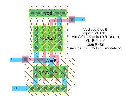
12 CMOS Inverter Taps in (b) to connect n-well and p-substrate to V DD and ground respectively 12

13 NAND and NOR Gate Layout students/adamsk5/lab6/nor_lay_sim.jpg

14 CMOS Gates Inverter, NAND2, NOR2 Two sample layouts of CMOS inverter circuits (for p-type substrate) 14

15 Chips Are 3D Sandwiches
16 Ensuring we can fabricate a working chip DESIGN RULES
 to verify")
17 Reminder: Layout Design Rules Lambda Rules: One lambda = one half of the minimum mask dimension, typically the length of a transistor channel Lambda Rules are based on the assumption that one can scale a design to the appropriate size before manufacturing Every spacing and sizing value is presented based on multiples of lambda The layout tool has a design rule checker (DRC) to verify those. In case of any violations the tool will point that out

18 CMOS NAND3 nmos and pmos transistors in series, and in parallel, respectively 18
19 CUSTOM OR STANDARD CELL ASIC (NOT FPGA) DESIGN FLOW
20 Digital Design Overview Circuit Design Layout Design Partitioning Verify the circuitry logic Floorplanning Compile a netlist Placement Routing A flowchart of digital From concept through testing and finally to a layout
21 After circuit design, we obtain a netlist which could be easily translated into a schematic. Now, let s start the layout design (a.k.a. physical design) Partitioning Layout Design Divide the chip into smaller blocks This is done based on some goals and constraints, e.g., to minimize the number of connections between the blocks, but in general it is done to separate different functional blocks and simplify their physical design process and also to make placement and routing easier For example, during partitioning you may decide to divide your design into two blocks, such that the total number of connections between the gates in different blocks is minimized
, RAM, MPU (Microprocessor), ROM on the chip Place the input and output (I/O) cells of your chip Connect functional blocks with I/O pads or")
22 Floorplanning Create functional areas for your chip. For example, decide where to place FPU (Floating Point Unit), RAM, MPU (Microprocessor), ROM on the chip Place the input and output (I/O) cells of your chip Connect functional blocks with I/O pads or with each other Check whether long wires would slow your design Placement Nail down the exact positions of all logic gates within each block Place I/O drivers Layout Design (cont.) Similarly to other steps, placement is done based on goals and constraints, e.g., such that the total approximate wire length is minimized
 Routing is typically done in two steps of global routing and detailed routing.")
23 Routing Route power nets and clock nets first. They are critical nets Route rest of the nets Layout Design (cont.) Routing is typically done in two steps of global routing and detailed routing. In global routing the resource (channels) for the wires are selected and in detailed routing, the wires are assigned to a specific routing track (metal layer) in the selected channels
24 Macro View of a Chip Place and route are very important aspects of design
25 Standard Cell Library Standard Cell Library Intellectual property provided by a vendor Has many pre-defined gates (cells) that are already laid out at various sizing levels for drive strength (to achieve desired delay) Design Flow You develop a design A synthesis software tool determines what cells are needed A place and route tool determines how to place them and route the input/output of each cell appropriately (i.e. using various metal layers) Example Cell_Lib_Rev1_4_20_1.pdf
26 FPGAS
 Circuits 1970 s Around a hundred gates per chip ( 283s and 85s) Very Large Scale Integrated (VLSI) Circuits 100 s of millions of")
27 Progression of Logic Density Small Scale Integrated (SSI) Circuits 1960 s and 1970 s A few gates on a chip Medium Scale Integrated (MSI) Circuits 1970 s Around a hundred gates per chip ( 283s and 85s) Very Large Scale Integrated (VLSI) Circuits 100 s of millions of gates
: Physical gates are created on silicon to implement 1 particular design FPGA (Field Programmable Gate Array s):")

 FPGA s have logic resources on them that we can configure to implement our specific design.")
28 Digital Design Targets Two possible implementation targets Custom Chips (ASIC s = Application Specific Integrated Circuits): Physical gates are created on silicon to implement 1 particular design FPGA (Field Programmable Gate Array s): Programmable logic using programmable memories to implement logic functions along with other logic resources tiled on the chip. Can implement any design and then be changed to implement a new one In an ASIC design, a unique chip will be manufactured that implements our design at which point the HW design is fixed & cannot be changed (example: Pentium, etc.) FPGA s have logic resources on them that we can configure to implement our specific design. We can then reconfigure it to implement another design
29 ASICs
30 Basis of FPGA s Memories provide a universal way to implement a logic function 2 n x m memory can implement a function of n-variables and m outputs C in Y X A 0 A 1 A 2 8x2 Memory If we use RWM (read/write memory) rather than ROM s we can change what function the memory implements Memories are referred to as Look-up Tables (LUT s) D 1 D 0 Cout S Full Adder Implementation
31 Configurable Logic Blocks (CLB s) Writable Look-Up Table D-FF s with bypass path Bypass mux selects the pure combinational output of the LUT or the registered/d-ff output Blue boxes indicate programmable bits that control the operation and function of the logic A 0 A 1 A 2 D CLK Q CLB 8x2 Mem D 1 D 0 D CLK Q Any 3-input / 2-output combinational function FF s if sequential logic needed
32 Routing & Switch Matrices Inputs and outputs of neighboring CLB s connect to a switch matrix (SM) Switch matrix is simply composed of muxes that allow us to route inputs and outputs to another CLB or further away CLB CLB CLB SM SM CLB CLB CLB SM SM CLB CLB CLB
33 Routing & Switch Matrices CLB To / from N SM A B C To / from W SM L A B... L A B... Switch Matrix (SM) L A B... L D E CLB CLB K J A B... L F To / from E SM I H G To / from S SM CLB
34 Place and Route ASIC: Find where each gate should be placed on the chip and how to route the wires that connect to it FPGA: Determine which LUT s should be used and how to route through switch matrices Affects timing and area wiring takes up space and longer wires leads to longer delays ASIC FPGA CLB CLB CLB SM SM CLB CLB CLB SM SM CLB CLB CLB
35 Exercise Find the configuration bits to build a 3-bit free-running (always enabled) counter Ci Q1 Q2 A 0 A 1 A 2 8x2 Mem CLB Q0 0 0 A 0 A 1 A 2 CLB 8x2 Mem Ci A Q0 B CLB 0 0 Q0 To / from N SM C D CLK Q D 1 D 0 D CLK Q Q2 Q D 1 D 0 D D CLK CLK Q Q Ci Q0 0 X = XXX X = XXX B = 001 A B... Switch Matrix (SM) L A B... L A = 000 D = 011 E = 100 Q1 D Q2 E Ci Q1 CLB Q2 To / from E SM F
36 Implementation ASIC s Use the CAD tools to synthesize and route a netlist Synthesis = Takes logic description or logic schematic & converts to transistor level gates Place and Route = Figure out where each gate should go on the chip) Final netlist is sent to chip maker for production Fabrication is very expensive (> $1 million) so get your design right the first time. FPGA s Synthesis converts logic description to necessary LUT contents, etc. Place and route produces a configuration for the FPGA chip Can reconfigure FPGA as much as you like, so less important to get it right 1 st time
37 ASIC s vs. FPGA s ASIC s Faster Handles Larger Designs More Expensive Less Flexible (Cannot be reconfigured to perform a new hardware function) FPGA s Slower (extra logic to make it reconfigurable) Smaller Designs Less Expensive Extremely Flexible
 7-Segment Displays (8) LED s (4) Push Buttons (8)")
38 Xilinx Spartan 3E Digilent Nexys-2 Board Has a Xilinx Spartan 3E FPGA (XC3S500e) 500K gate equivalent 9312 D-FF s on-board On-board I/O (4) 7-Segment Displays (8) LED s (4) Push Buttons (8) Switches
39 Latest FPGA's SoC design (Xilinx Kintex [KU115]) Quad-Core ARM cores DDR3 SDRAM Memory Interface ~800 I/O Pins Equiv. ~15M gate equivalent FPGA fabric ~1M D-FFs + 552K LUTs 1968 dedicated DSP "slices" 18x18 multiply + adder 34.6 Megabits of onboard Block RAMs
Learning Outcomes. Spiral 3 1. Digital Design Targets ASICS & FPGAS REVIEW. Hardware/Software Interfacing
 3-. 3-.2 Learning Outcomes Spiral 3 Hardware/Software Interfacing I understand the PicoBlaze bus interface signals: PORT_ID, IN_PORT, OUT_PORT, WRITE_STROBE I understand how a memory map provides the agreement
Spiral 3-1. Hardware/Software Interfacing
 3-1.1 Spiral 3-1 Hardware/Software Interfacing 3-1.2 Learning Outcomes I understand the PicoBlaze bus interface signals: PORT_ID, IN_PORT, OUT_PORT, WRITE_STROBE I understand how a memory map provides
FPGA for Complex System Implementation. National Chiao Tung University Chun-Jen Tsai 04/14/2011
 FPGA for Complex System Implementation National Chiao Tung University Chun-Jen Tsai 04/14/2011 About FPGA FPGA was invented by Ross Freeman in 1989 SRAM-based FPGA properties Standard parts Allowing multi-level
Design Methodologies. Full-Custom Design
 Design Methodologies Design styles Full-custom design Standard-cell design Programmable logic Gate arrays and field-programmable gate arrays (FPGAs) Sea of gates System-on-a-chip (embedded cores) Design
PROGRAMMABLE MODULES SPECIFICATION OF PROGRAMMABLE COMBINATIONAL AND SEQUENTIAL MODULES
 PROGRAMMABLE MODULES SPECIFICATION OF PROGRAMMABLE COMBINATIONAL AND SEQUENTIAL MODULES. psa. rom. fpga THE WAY THE MODULES ARE PROGRAMMED NETWORKS OF PROGRAMMABLE MODULES EXAMPLES OF USES Programmable
FABRICATION TECHNOLOGIES
 FABRICATION TECHNOLOGIES DSP Processor Design Approaches Full custom Standard cell** higher performance lower energy (power) lower per-part cost Gate array* FPGA* Programmable DSP Programmable general
INTRODUCTION TO FPGA ARCHITECTURE
 3/3/25 INTRODUCTION TO FPGA ARCHITECTURE DIGITAL LOGIC DESIGN (BASIC TECHNIQUES) a b a y 2input Black Box y b Functional Schematic a b y a b y a b y 2 Truth Table (AND) Truth Table (OR) Truth Table (XOR)
Design Methodologies
 Design Methodologies 1981 1983 1985 1987 1989 1991 1993 1995 1997 1999 2001 2003 2005 2007 2009 Complexity Productivity (K) Trans./Staff - Mo. Productivity Trends Logic Transistor per Chip (M) 10,000 0.1
CS310 Embedded Computer Systems. Maeng
 1 INTRODUCTION (PART II) Maeng Three key embedded system technologies 2 Technology A manner of accomplishing a task, especially using technical processes, methods, or knowledge Three key technologies for
UNIVERSITY OF CALIFORNIA College of Engineering Department of Electrical Engineering and Computer Sciences Lab #2: Layout and Simulation
 UNIVERSITY OF CALIFORNIA College of Engineering Department of Electrical Engineering and Computer Sciences Lab #2: Layout and Simulation NTU IC541CA 1 Assumed Knowledge This lab assumes use of the Electric
Design Methodologies and Tools. Full-Custom Design
 Design Methodologies and Tools Design styles Full-custom design Standard-cell design Programmable logic Gate arrays and field-programmable gate arrays (FPGAs) Sea of gates System-on-a-chip (embedded cores)
ESE 570 Cadence Lab Assignment 2: Introduction to Spectre, Manual Layout Drawing and Post Layout Simulation (PLS)
") ESE 570 Cadence Lab Assignment 2: Introduction to Spectre, Manual Layout Drawing and Post Layout Simulation (PLS) Objective Part A: To become acquainted with Spectre (or HSpice) by simulating an inverter,
ESE 570 Cadence Lab Assignment 2: Introduction to Spectre, Manual Layout Drawing and Post Layout Simulation (PLS) Objective Part A: To become acquainted with Spectre (or HSpice) by simulating an inverter,
EE 330 Laboratory 3 Layout, DRC, and LVS Fall 2015
 EE 330 Laboratory 3 Layout, DRC, and LVS Fall 2015 Contents Objective:... 2 Part 1 Creating a layout... 2 1.1 Run DRC Early and Often... 2 1.2 Create N active and connect the transistors... 3 1.3 Vias...
EE 330 Laboratory 3 Layout, DRC, and LVS
 EE 330 Laboratory 3 Layout, DRC, and LVS Spring 2018 Contents Objective:... 2 Part 1 creating a layout... 2 1.1 Run DRC... 2 1.2 Stick Diagram to Physical Layer... 3 1.3 Bulk Connections... 3 1.4 Pins...
EECS150 - Digital Design Lecture 6 - Field Programmable Gate Arrays (FPGAs)
") EECS150 - Digital Design Lecture 6 - Field Programmable Gate Arrays (FPGAs) September 12, 2002 John Wawrzynek Fall 2002 EECS150 - Lec06-FPGA Page 1 Outline What are FPGAs? Why use FPGAs (a short history
EECS150 - Digital Design Lecture 6 - Field Programmable Gate Arrays (FPGAs) September 12, 2002 John Wawrzynek Fall 2002 EECS150 - Lec06-FPGA Page 1 Outline What are FPGAs? Why use FPGAs (a short history
Outline. EECS150 - Digital Design Lecture 6 - Field Programmable Gate Arrays (FPGAs) FPGA Overview. Why FPGAs?
 FPGA Overview. Why FPGAs?") EECS150 - Digital Design Lecture 6 - Field Programmable Gate Arrays (FPGAs) September 12, 2002 John Wawrzynek Outline What are FPGAs? Why use FPGAs (a short history lesson). FPGA variations Internal logic
EECS150 - Digital Design Lecture 6 - Field Programmable Gate Arrays (FPGAs) September 12, 2002 John Wawrzynek Outline What are FPGAs? Why use FPGAs (a short history lesson). FPGA variations Internal logic
Design Methodologies. Digital Integrated Circuits A Design Perspective. Jan M. Rabaey Anantha Chandrakasan Borivoje Nikolic.
 Digital Integrated Circuits A Design Perspective Jan M. Rabaey Anantha Chandrakasan Borivoje Nikolic Design Methodologies December 10, 2002 L o g i c T r a n s i s t o r s p e r C h i p ( K ) 1 9 8 1 1
Lab. Course Goals. Topics. What is VLSI design? What is an integrated circuit? VLSI Design Cycle. VLSI Design Automation
 Course Goals Lab Understand key components in VLSI designs Become familiar with design tools (Cadence) Understand design flows Understand behavioral, structural, and physical specifications Be able to
CHAPTER 12 ARRAY SUBSYSTEMS [ ] MANJARI S. KULKARNI
![CHAPTER 12 ARRAY SUBSYSTEMS [ ] MANJARI S. KULKARNI](/thumbs/76/73997056.jpg "CHAPTER 12 ARRAY SUBSYSTEMS [ ] MANJARI S. KULKARNI") CHAPTER 2 ARRAY SUBSYSTEMS [2.4-2.9] MANJARI S. KULKARNI OVERVIEW Array classification Non volatile memory Design and Layout Read-Only Memory (ROM) Pseudo nmos and NAND ROMs Programmable ROMS PROMS, EPROMs,
CHAPTER 2 ARRAY SUBSYSTEMS [2.4-2.9] MANJARI S. KULKARNI OVERVIEW Array classification Non volatile memory Design and Layout Read-Only Memory (ROM) Pseudo nmos and NAND ROMs Programmable ROMS PROMS, EPROMs,
Programmable Logic Devices FPGA Architectures II CMPE 415. Overview This set of notes introduces many of the features available in the FPGAs of today.
 Overview This set of notes introduces many of the features available in the FPGAs of today. The majority use SRAM based configuration cells, which allows fast reconfiguation. Allows new design ideas to
ECE 459/559 Secure & Trustworthy Computer Hardware Design
 ECE 459/559 Secure & Trustworthy Computer Hardware Design VLSI Design Basics Garrett S. Rose Spring 2016 Recap Brief overview of VHDL Behavioral VHDL Structural VHDL Simple examples with VHDL Some VHDL
INTRODUCTION TO FIELD PROGRAMMABLE GATE ARRAYS (FPGAS)
") INTRODUCTION TO FIELD PROGRAMMABLE GATE ARRAYS (FPGAS) Bill Jason P. Tomas Dept. of Electrical and Computer Engineering University of Nevada Las Vegas FIELD PROGRAMMABLE ARRAYS Dominant digital design
INTRODUCTION TO FIELD PROGRAMMABLE GATE ARRAYS (FPGAS) Bill Jason P. Tomas Dept. of Electrical and Computer Engineering University of Nevada Las Vegas FIELD PROGRAMMABLE ARRAYS Dominant digital design
DIGITAL DESIGN TECHNOLOGY & TECHNIQUES
 DIGITAL DESIGN TECHNOLOGY & TECHNIQUES CAD for ASIC Design 1 INTEGRATED CIRCUITS (IC) An integrated circuit (IC) consists complex electronic circuitries and their interconnections. William Shockley et
! Program logic functions, interconnect using SRAM. ! Advantages: ! Re-programmable; ! dynamically reconfigurable; ! uses standard processes.
 Topics! SRAM-based FPGA fabrics:! Xilinx.! Altera. SRAM-based FPGAs! Program logic functions, using SRAM.! Advantages:! Re-programmable;! dynamically reconfigurable;! uses standard processes.! isadvantages:!
Overview. CSE372 Digital Systems Organization and Design Lab. Hardware CAD. Two Types of Chips
 Overview CSE372 Digital Systems Organization and Design Lab Prof. Milo Martin Unit 5: Hardware Synthesis CAD (Computer Aided Design) Use computers to design computers Virtuous cycle Architectural-level,
Digital Integrated Circuits (83-313) Lecture 2: Technology and Standard Cell Layout
 Lecture 2: Technology and Standard Cell Layout") Digital Integrated Circuits (83-313) Lecture 2: Technology and Standard Cell Layout Semester B, 2016-17 Lecturer: Dr. Adam Teman TAs: Itamar Levi, Robert Giterman 26 March 2017 Disclaimer: This course
Digital Integrated Circuits (83-313) Lecture 2: Technology and Standard Cell Layout Semester B, 2016-17 Lecturer: Dr. Adam Teman TAs: Itamar Levi, Robert Giterman 26 March 2017 Disclaimer: This course
Very Large Scale Integration (VLSI)
") Very Large Scale Integration (VLSI) Lecture 6 Dr. Ahmed H. Madian Ah_madian@hotmail.com Dr. Ahmed H. Madian-VLSI 1 Contents FPGA Technology Programmable logic Cell (PLC) Mux-based cells Look up table PLA
Very Large Scale Integration (VLSI) Lecture 6 Dr. Ahmed H. Madian Ah_madian@hotmail.com Dr. Ahmed H. Madian-VLSI 1 Contents FPGA Technology Programmable logic Cell (PLC) Mux-based cells Look up table PLA
Digital Design Methodology (Revisited) Design Methodology: Big Picture
 Design Methodology: Big Picture") Digital Design Methodology (Revisited) Design Methodology Design Specification Verification Synthesis Technology Options Full Custom VLSI Standard Cell ASIC FPGA CS 150 Fall 2005 - Lec #25 Design Methodology
Digital Design Methodology (Revisited) Design Methodology Design Specification Verification Synthesis Technology Options Full Custom VLSI Standard Cell ASIC FPGA CS 150 Fall 2005 - Lec #25 Design Methodology
3. Implementing Logic in CMOS
 3. Implementing Logic in CMOS 3. Implementing Logic in CMOS Jacob Abraham Department of Electrical and Computer Engineering The University of Texas at Austin VLSI Design Fall 27 September, 27 ECE Department,
CPE/EE 422/522. Introduction to Xilinx Virtex Field-Programmable Gate Arrays Devices. Dr. Rhonda Kay Gaede UAH. Outline
 CPE/EE 422/522 Introduction to Xilinx Virtex Field-Programmable Gate Arrays Devices Dr. Rhonda Kay Gaede UAH Outline Introduction Field-Programmable Gate Arrays Virtex Virtex-E, Virtex-II, and Virtex-II
Digital Integrated Circuits
 Digital Integrated Circuits Lecture 9 Jaeyong Chung Robust Systems Laboratory Incheon National University DIGITAL DESIGN FLOW Chung EPC6055 2 FPGA vs. ASIC FPGA (A programmable Logic Device) Faster time-to-market
Digital Design Methodology
 Digital Design Methodology Prof. Soo-Ik Chae Digital System Designs and Practices Using Verilog HDL and FPGAs @ 2008, John Wiley 1-1 Digital Design Methodology (Added) Design Methodology Design Specification
TUTORIAL II ECE 555 / 755 Updated on September 11 th 2006 CADENCE LAYOUT AND PARASITIC EXTRACTION
 TUTORIAL II ECE 555 / 755 Updated on September 11 th 2006 CADENCE LAYOUT AND PARASITIC EXTRACTION After finishing a schematic of your design (Tutorial-I), the next step is creating masks which are for
Chapter 5: ASICs Vs. PLDs
 Chapter 5: ASICs Vs. PLDs 5.1 Introduction A general definition of the term Application Specific Integrated Circuit (ASIC) is virtually every type of chip that is designed to perform a dedicated task.
UNIT 4 INTEGRATED CIRCUIT DESIGN METHODOLOGY E5163
 UNIT 4 INTEGRATED CIRCUIT DESIGN METHODOLOGY E5163 LEARNING OUTCOMES 4.1 DESIGN METHODOLOGY By the end of this unit, student should be able to: 1. Explain the design methodology for integrated circuit.
Evolution of Implementation Technologies. ECE 4211/5211 Rapid Prototyping with FPGAs. Gate Array Technology (IBM s) Programmable Logic
 Programmable Logic") ECE 42/52 Rapid Prototyping with FPGAs Dr. Charlie Wang Department of Electrical and Computer Engineering University of Colorado at Colorado Springs Evolution of Implementation Technologies Discrete devices:
ECE 42/52 Rapid Prototyping with FPGAs Dr. Charlie Wang Department of Electrical and Computer Engineering University of Colorado at Colorado Springs Evolution of Implementation Technologies Discrete devices:
FPGA: What? Why? Marco D. Santambrogio
 FPGA: What? Why? Marco D. Santambrogio marco.santambrogio@polimi.it 2 Reconfigurable Hardware Reconfigurable computing is intended to fill the gap between hardware and software, achieving potentially much
PINE TRAINING ACADEMY
 PINE TRAINING ACADEMY Course Module A d d r e s s D - 5 5 7, G o v i n d p u r a m, G h a z i a b a d, U. P., 2 0 1 0 1 3, I n d i a Digital Logic System Design using Gates/Verilog or VHDL and Implementation
Today. Comments about assignment Max 1/T (skew = 0) Max clock skew? Comments about assignment 3 ASICs and Programmable logic Others courses
 Max clock skew? Comments about assignment 3 ASICs and Programmable logic Others courses") Today Comments about assignment 3-43 Comments about assignment 3 ASICs and Programmable logic Others courses octor Per should show up in the end of the lecture Mealy machines can not be coded in a single
Today Comments about assignment 3-43 Comments about assignment 3 ASICs and Programmable logic Others courses octor Per should show up in the end of the lecture Mealy machines can not be coded in a single
Graphics: Alexandra Nolte, Gesine Marwedel, Universität Dortmund. RTL Synthesis
 Graphics: Alexandra Nolte, Gesine Marwedel, 2003 Universität Dortmund RTL Synthesis Purpose of HDLs Purpose of Hardware Description Languages: Capture design in Register Transfer Language form i.e. All
CMPEN 411 VLSI Digital Circuits Spring Lecture 22: Memery, ROM
 CMPEN 411 VLSI Digital Circuits Spring 2011 Lecture 22: Memery, ROM [Adapted from Rabaey s Digital Integrated Circuits, Second Edition, 2003 J. Rabaey, A. Chandrakasan, B. Nikolic] Sp11 CMPEN 411 L22 S.1
COE 561 Digital System Design & Synthesis Introduction
 1 COE 561 Digital System Design & Synthesis Introduction Dr. Aiman H. El-Maleh Computer Engineering Department King Fahd University of Petroleum & Minerals Outline Course Topics Microelectronics Design
Synthesis of VHDL Code for FPGA Design Flow Using Xilinx PlanAhead Tool
 Synthesis of VHDL Code for FPGA Design Flow Using Xilinx PlanAhead Tool Md. Abdul Latif Sarker, Moon Ho Lee Division of Electronics & Information Engineering Chonbuk National University 664-14 1GA Dekjin-Dong
EE 466/586 VLSI Design. Partha Pande School of EECS Washington State University
 EE 466/586 VLSI Design Partha Pande School of EECS Washington State University pande@eecs.wsu.edu Lecture 18 Implementation Methods The Design Productivity Challenge Logic Transistors per Chip (K) 10,000,000.10m
Design rule illustrations for the AMI C5N process can be found at:
 Cadence Tutorial B: Layout, DRC, Extraction, and LVS Created for the MSU VLSI program by Professor A. Mason and the AMSaC lab group. Revised by C Young & Waqar A Qureshi -FS08 Document Contents Introduction
Digital Integrated Circuits A Design Perspective. Jan M. Rabaey
 Digital Integrated Circuits A Design Perspective Jan M. Rabaey Outline (approximate) Introduction and Motivation The VLSI Design Process Details of the MOS Transistor Device Fabrication Design Rules CMOS
Lay ay ut Design g R ules
 HPTER 5: Layout esign Rules Introduction ny circuit physical mask layout must conform to a set of geometric constraints or rules called as Layout esign rules before it can be manufactured using particular
Introduction to ICs and Transistor Fundamentals
 Introduction to ICs and Transistor Fundamentals A Brief History 1958: First integrated circuit Flip-flop using two transistors Built by Jack Kilby at Texas Instruments 2003 Intel Pentium 4 mprocessor (55
Digital Integrated CircuitDesign
 Digital Integrated CircuitDesign Lecture 8 Design Rules Adib Abrishamifar EE Department IUST Contents Design Rules CMOS Process Layers Intra-Layer Design Rules Via s and Contacts Select Layer Example Cell
Memory and Programmable Logic
 Digital Circuit Design and Language Memory and Programmable Logic Chang, Ik Joon Kyunghee University Memory Classification based on functionality ROM : Read-Only Memory RWM : Read-Write Memory RWM NVRWM
Field Programmable Gate Array (FPGA)
") Field Programmable Gate Array (FPGA) Lecturer: Krébesz, Tamas 1 FPGA in general Reprogrammable Si chip Invented in 1985 by Ross Freeman (Xilinx inc.) Combines the advantages of ASIC and uc-based systems
Field Programmable Gate Array (FPGA) Lecturer: Krébesz, Tamas 1 FPGA in general Reprogrammable Si chip Invented in 1985 by Ross Freeman (Xilinx inc.) Combines the advantages of ASIC and uc-based systems
UNIVERSITY OF WATERLOO
 UNIVERSITY OF WATERLOO UW ASIC DESIGN TEAM: Cadence Tutorial Description: Part I: Layout & DRC of a CMOS inverter. Part II: Extraction & LVS of a CMOS inverter. Part III: Post-Layout Simulation. The Cadence
CMOS INVERTER LAYOUT TUTORIAL
 PRINCESS SUMAYA UNIVERSITY FOR TECHNOLOGY CMOS INVERTER LAYOUT TUTORIAL We will start the inverter by drawing a PMOS. The first step is to draw a poly layer. Click on draw a rectangle and choose the poly
Hardware Design Environments. Dr. Mahdi Abbasi Computer Engineering Department Bu-Ali Sina University
 Hardware Design Environments Dr. Mahdi Abbasi Computer Engineering Department Bu-Ali Sina University Outline Welcome to COE 405 Digital System Design Design Domains and Levels of Abstractions Synthesis
FPGA architecture and design technology
 CE 435 Embedded Systems Spring 2017 FPGA architecture and design technology Nikos Bellas Computer and Communications Engineering Department University of Thessaly 1 FPGA fabric A generic island-style FPGA
What is Xilinx Design Language?
 Bill Jason P. Tomas University of Nevada Las Vegas Dept. of Electrical and Computer Engineering What is Xilinx Design Language? XDL is a human readable ASCII format compatible with the more widely used
FPGA Programming Technology
 FPGA Programming Technology Static RAM: This Xilinx SRAM configuration cell is constructed from two cross-coupled inverters and uses a standard CMOS process. The configuration cell drives the gates of
The Xilinx XC6200 chip, the software tools and the board development tools
 The Xilinx XC6200 chip, the software tools and the board development tools What is an FPGA? Field Programmable Gate Array Fully programmable alternative to a customized chip Used to implement functions
Experiment 3. Digital Circuit Prototyping Using FPGAs
 Experiment 3. Digital Circuit Prototyping Using FPGAs Masud ul Hasan Muhammad Elrabaa Ahmad Khayyat Version 151, 11 September 2015 Table of Contents 1. Objectives 2. Materials Required 3. Background 3.1.
ASIC Physical Design Top-Level Chip Layout
 ASIC Physical Design Top-Level Chip Layout References: M. Smith, Application Specific Integrated Circuits, Chap. 16 Cadence Virtuoso User Manual Top-level IC design process Typically done before individual
Lab 2. Standard Cell layout.
 Lab 2. Standard Cell layout. The purpose of this lab is to demonstrate CMOS-standard cell design. Use the lab instructions and the cadence manual (http://www.es.lth.se/ugradcourses/cadsys/cadence.html)
SP3Q.3. What makes it a good idea to put CRC computation and error-correcting code computation into custom hardware?
 Part II CST: SoC D/M: Quick exercises S3-S4 (examples sheet) Feb 2018 (rev a). This sheet contains short exercises for quick revision. Please also look at past exam questions and/or try some of the longer
More Course Information
 More Course Information Labs and lectures are both important Labs: cover more on hands-on design/tool/flow issues Lectures: important in terms of basic concepts and fundamentals Do well in labs Do well
Outline. Field Programmable Gate Arrays. Programming Technologies Architectures. Programming Interfaces. Historical perspective
 Outline Field Programmable Gate Arrays Historical perspective Programming Technologies Architectures PALs, PLDs,, and CPLDs FPGAs Programmable logic Interconnect network I/O buffers Specialized cores Programming
Virtuoso Layout Editor
 This tutorial will cover the basic steps involved in using the Cadence layout editor called Virtuoso, extracting layout, and running simulation on the layout. The inverter layout is used as an example
CMOS Process Flow. Layout CAD Tools
 CMOS Process Flow See supplementary power point file for animated CMOS process flow (see class ece410 website and/or* http://www.multimedia.vt.edu/ee5545/): This file should be viewed as a slide show It
Composite Layout CS/EE N-type from the top. N-type Transistor. Diffusion Mask. Polysilicon Mask
 Composite Layout CS/EE 6710 Introduction to Layout Inverter Layout Example Layout Design Rules Drawing the mask layers that will be used by the fabrication folks to make the devices Very different from
Physical Implementation
 CS250 VLSI Systems Design Fall 2009 John Wawrzynek, Krste Asanovic, with John Lazzaro Physical Implementation Outline Standard cell back-end place and route tools make layout mostly automatic. However,
Circuits. L3: Fabrication and Layout -1 ( ) B. Mazhari Dept. of EE, IIT Kanpur. B. Mazhari, IITK. G-Number
 B. Mazhari Dept. of EE, IIT Kanpur. B. Mazhari, IITK. G-Number") EE60: CMOS Analog Circuits L: Fabrication and Layout - (8.8.0) B. Mazhari Dept. of EE, IIT Kanpur Suppose we have a Silicon wafer which is P-type and we wish to create a region within it which is N-type
EE60: CMOS Analog Circuits L: Fabrication and Layout - (8.8.0) B. Mazhari Dept. of EE, IIT Kanpur Suppose we have a Silicon wafer which is P-type and we wish to create a region within it which is N-type
Review. EECS Components and Design Techniques for Digital Systems. Lec 03 Field Programmable Gate Arrays
 EECS 5 - Components and Design Techniques for Digital Systems Lec 3 Field Programmable Gate Arrays 9-4-7 David Culler Electrical Engineering and Computer Sciences University of California, Berkeley http://www.eecs.berkeley.edu/~culler
CPE/EE 427, CPE 527, VLSI Design I: Tutorial #1, Full Custom VLSI (inverter layout)
") CPE/EE 427, CPE 527, VLSI Design I: Tutorial #1, Full Custom VLSI (inverter layout) Joel Wilder, Aleksandar Milenkovic, ECE Dept., The University of Alabama in Huntsville Adapted from Virginia Tech, Dept.
CPE/EE 427, CPE 527, VLSI Design I: Tutorial #1, Full Custom VLSI (inverter layout) Joel Wilder, Aleksandar Milenkovic, ECE Dept., The University of Alabama in Huntsville Adapted from Virginia Tech, Dept.
ESE370: Circuit-Level Modeling, Design, and Optimization for Digital Systems
 ESE370: Circuit-Level Modeling, Design, and Optimization for Digital Systems Lec 26: November 9, 2018 Memory Overview Dynamic OR4! Precharge time?! Driving input " With R 0 /2 inverter! Driving inverter
Hardware Design with VHDL PLDs I ECE 443. FPGAs can be configured at least once, many are reprogrammable.
 PLDs, ASICs and FPGAs FPGA definition: Digital integrated circuit that contains configurable blocks of logic and configurable interconnects between these blocks. Key points: Manufacturer does NOT determine
Introduction to Microprocessor
 Introduction to Microprocessor Slide 1 Microprocessor A microprocessor is a multipurpose, programmable, clock-driven, register-based electronic device That reads binary instructions from a storage device
FIELD PROGRAMMABLE GATE ARRAYS (FPGAS)
") FIELD PROGRAMMABLE GATE ARRAYS (FPGAS) 1 Roth Text: Chapter 3 (section 3.4) Chapter 6 Nelson Text: Chapter 11 Programmable logic taxonomy Lab Device 2 Field Programmable Gate Arrays Typical Complexity
FIELD PROGRAMMABLE GATE ARRAYS (FPGAS) 1 Roth Text: Chapter 3 (section 3.4) Chapter 6 Nelson Text: Chapter 11 Programmable logic taxonomy Lab Device 2 Field Programmable Gate Arrays Typical Complexity
Hardware Design with VHDL PLDs IV ECE 443
 Embedded Processor Cores (Hard and Soft) Electronic design can be realized in hardware (logic gates/registers) or software (instructions executed on a microprocessor). The trade-off is determined by how
discrete logic do not
 Welcome to my second year course on Digital Electronics. You will find that the slides are supported by notes embedded with the Powerpoint presentations. All my teaching materials are also available on
Digital Electronics 27. Digital System Design using PLDs
 1 Module -27 Digital System Design 1. Introduction 2. Digital System Design 2.1 Standard (Fixed function) ICs based approach 2.2 Programmable ICs based approach 3. Comparison of Digital System Design approaches
FPGA VHDL Design Flow AES128 Implementation
 Sakinder Ali FPGA VHDL Design Flow AES128 Implementation Field Programmable Gate Array Basic idea: two-dimensional array of logic blocks and flip-flops with a means for the user to configure: 1. The interconnection
Topics. ! PLAs.! Memories: ! Datapaths.! Floor Planning ! ROM;! SRAM;! DRAM. Modern VLSI Design 2e: Chapter 6. Copyright 1994, 1998 Prentice Hall
 Topics! PLAs.! Memories:! ROM;! SRAM;! DRAM.! Datapaths.! Floor Planning Programmable logic array (PLA)! Used to implement specialized logic functions.! A PLA decodes only some addresses (input values);
ECEN 449 Microprocessor System Design. FPGAs and Reconfigurable Computing
 ECEN 449 Microprocessor System Design FPGAs and Reconfigurable Computing Some of the notes for this course were developed using the course notes for ECE 412 from the University of Illinois, Urbana-Champaign
Introduction to SRAM. Jasur Hanbaba
 Introduction to SRAM Jasur Hanbaba Outline Memory Arrays SRAM Architecture SRAM Cell Decoders Column Circuitry Non-volatile Memory Manufacturing Flow Memory Arrays Memory Arrays Random Access Memory Serial
Workspace for '4-FPGA' Page 1 (row 1, column 1)
") Workspace for '4-FPGA' Page 1 (row 1, column 1) Workspace for '4-FPGA' Page 2 (row 2, column 1) Workspace for '4-FPGA' Page 3 (row 3, column 1) ECEN 449 Microprocessor System Design FPGAs and Reconfigurable
Workspace for '4-FPGA' Page 1 (row 1, column 1) Workspace for '4-FPGA' Page 2 (row 2, column 1) Workspace for '4-FPGA' Page 3 (row 3, column 1) ECEN 449 Microprocessor System Design FPGAs and Reconfigurable
CMPE 413/ CMSC 711. Project Specification: 16 bit 2 s complement Adder and 8 bit 2 s complement multiplier. GND. Input bus. Latches I[8]-I[15]
![CMPE 413/ CMSC 711. Project Specification: 16 bit 2 s complement Adder and 8 bit 2 s complement multiplier. GND. Input bus. Latches I[8]-I[15]](/thumbs/72/67338890.jpg "CMPE 413/ CMSC 711. Project Specification: 16 bit 2 s complement Adder and 8 bit 2 s complement multiplier. GND. Input bus. Latches I[8]-I[15]") Project Specification: 16 bit 2 s complement Adder and 8 bit 2 s complement multiplier. Assigned: Fri, Nov 3rd Due: Tue, Dec. 19th Description: con1 I[15] I[14] I[13] GND I[12] I[11] I[10] I[9] con2 O[15]
Project Specification: 16 bit 2 s complement Adder and 8 bit 2 s complement multiplier. Assigned: Fri, Nov 3rd Due: Tue, Dec. 19th Description: con1 I[15] I[14] I[13] GND I[12] I[11] I[10] I[9] con2 O[15]
UNIT IV CMOS TESTING
 UNIT IV CMOS TESTING 1. Mention the levels at which testing of a chip can be done? At the wafer level At the packaged-chip level At the board level At the system level In the field 2. What is meant by
FPGA. Logic Block. Plessey FPGA: basic building block here is 2-input NAND gate which is connected to each other to implement desired function.
 FPGA Logic block of an FPGA can be configured in such a way that it can provide functionality as simple as that of transistor or as complex as that of a microprocessor. It can used to implement different
Motivation for Lecture. Market for Memories. Example: FFT Design. Sequential Circuits & D flip-flop. Latches and Registers.
 Motivation for Lecture Design Methodologies Storage (registers and memories) Computational platforms Design Methodologies Memories is a crucial part of most designs: What different type of memories are
SIDDHARTH INSTITUTE OF ENGINEERING AND TECHNOLOGY :: PUTTUR (AUTONOMOUS) Siddharth Nagar, Narayanavanam Road QUESTION BANK UNIT I
 Siddharth Nagar, Narayanavanam Road QUESTION BANK UNIT I") SIDDHARTH INSTITUTE OF ENGINEERING AND TECHNOLOGY :: PUTTUR (AUTONOMOUS) Siddharth Nagar, Narayanavanam Road 517583 QUESTION BANK Subject with Code : DICD (16EC5703) Year & Sem: I-M.Tech & I-Sem Course
SIDDHARTH INSTITUTE OF ENGINEERING AND TECHNOLOGY :: PUTTUR (AUTONOMOUS) Siddharth Nagar, Narayanavanam Road 517583 QUESTION BANK Subject with Code : DICD (16EC5703) Year & Sem: I-M.Tech & I-Sem Course
Lecture 2: MIPS Processor Example
 Introduction to CMOS VLSI Design Lecture 2: MIPS Processor Example Outline Design Partitioning MIPS Processor Example Architecture t Microarchitecture Logic Design Circuit Design Physical Design Fabrication,
EECE 285 VLSI Design. Cadence Tutorial EECE 285 VLSI. By: Kevin Dick Co-author: Jeff Kauppila Co-author: Dr. Arthur Witulski
 Cadence Tutorial EECE 285 VLSI By: Kevin Dick Co-author: Jeff Kauppila Co-author: Dr. Arthur Witulski 1 Table of Contents Purpose of Cadence 1) The Purpose of Cadence pg. 4 Linux 1) The Purpose of Linux
A VARIETY OF ICS ARE POSSIBLE DESIGNING FPGAS & ASICS. APPLICATIONS MAY USE STANDARD ICs or FPGAs/ASICs FAB FOUNDRIES COST BILLIONS
 architecture behavior of control is if left_paddle then n_state
ECE 545 Lecture 12. FPGA Resources. George Mason University
 ECE 545 Lecture 2 FPGA Resources George Mason University Recommended reading 7 Series FPGAs Configurable Logic Block: User Guide Overview Functional Details 2 What is an FPGA? Configurable Logic Blocks
The QR code here provides a shortcut to go to the course webpage.
 Welcome to this MSc Lab Experiment. All my teaching materials for this Lab-based module are also available on the webpage: www.ee.ic.ac.uk/pcheung/teaching/msc_experiment/ The QR code here provides a shortcut
Introduction to Field Programmable Gate Arrays
 Introduction to Field Programmable Gate Arrays Lecture 1/3 CERN Accelerator School on Digital Signal Processing Sigtuna, Sweden, 31 May 9 June 2007 Javier Serrano, CERN AB-CO-HT Outline Historical introduction.
RTL Coding General Concepts
 RTL Coding General Concepts Typical Digital System 2 Components of a Digital System Printed circuit board (PCB) Embedded d software microprocessor microcontroller digital signal processor (DSP) ASIC Programmable
CMOS VLSI Design. MIPS Processor Example. Outline
 COS VLSI Design IPS Processor Example Outline Design Partitioning IPS Processor Example Architecture icroarchitecture Logic Design Circuit Design Physical Design Fabrication, Packaging, Testing Slide 2
Memory. Outline. ECEN454 Digital Integrated Circuit Design. Memory Arrays. SRAM Architecture DRAM. Serial Access Memories ROM
 ECEN454 Digital Integrated Circuit Design Memory ECEN 454 Memory Arrays SRAM Architecture SRAM Cell Decoders Column Circuitry Multiple Ports DRAM Outline Serial Access Memories ROM ECEN 454 12.2 1 Memory
Advanced FPGA Design Methodologies with Xilinx Vivado
 Advanced FPGA Design Methodologies with Xilinx Vivado Alexander Jäger Computer Architecture Group Heidelberg University, Germany Abstract With shrinking feature sizes in the ASIC manufacturing technology,
Memory in Digital Systems
 MEMORIES Memory in Digital Systems Three primary components of digital systems Datapath (does the work) Control (manager) Memory (storage) Single bit ( foround ) Clockless latches e.g., SR latch Clocked
EE 434 ASIC & Digital Systems
 EE 434 ASIC & Digital Systems Dae Hyun Kim EECS Washington State University Spring 2018 Course Website http://eecs.wsu.edu/~ee434 Themes Study how to design, analyze, and test a complex applicationspecific