ver INDU WRC-2000 Controller User s Manual
|
|
|
- Annice Cole
- 5 years ago
- Views:
Transcription
1 ver INDU WRC-2000 Controller User s Manual Sp. z o.o. [Ltd.] Czeladź, ul. Wojkowicka 21, Poland Tel Fax: info@mikster.com v
2 TABLE OF CONTENTS 1. STRUCTURE, APPLICATIONS, POTENTIAL INDU WRC CONTROL PANEL INDU WRC START OF OPERATION PROCESS PROGRAMS Manufacturing process programming Execution of program stored in memory Program execution interruption Automatic process activation Editing of parameters set during controller operation CONTROLLER CONFIGURATION User s functions Time and date setting Setting menu language Service functions Controller parameter setting Setting of step parameters Alarm setting Parameter setting for pause mode, stop mode and key functions F1..F I/O output parameter setting Washing parameter setting Service functions Test for digital outputs Key test Diode test Washing Washing programming Washing activation ADDITIONAL INFORMATION Display of additional measurements HOW TO CONNECT THE CONTROLLER TO PC COMPUTER TECHNICAL DATA...34 II INDU WRC CPU-01 MODULE MODULE ASSEMBLING MODULE FUNCTION FIGURE TECHNICAL DATA...36 III. INDU WRC AI-01/6 MODULE MODULE ASSEMBLING MODULE FUNCTION FIGURE TECHNICAL DATA...38 IV. INDU WRC DI-01MODULE MODULE ASSEMBLING MODULE FUNCTIONS FIGURE TECHNICAL DATA...40 V. INDU WRC RO-01 MODULE...41 page
3 1. MODULE ASSEMBLING MODULE FUNCTIONS FIGURE TECHNICAL DATA CARDS ADDRESSING IN THE SYSTEM:...42 VI. INDU WRC TO-01 MODULE MODULE ASSEMBLING MODULE FUNCTION FIGURE TECHNICAL DATA CARDS ADDRESSING IN THE SYSTEM:...44 VII. INDU WRC COM-01 MODULE MODULE ASSEMBLING MODULE FUNCTION FIGURE TECHNICAL DATA...46 VIII. INDU WRC PS-01 MODULE MODULE ASSEMBLING MODULE FUNCTION FIGURE TECHNICAL DATA
4 1. STRUCTURE, APPLICATIONS, POTENTIAL The INDU WRC-2000 Controller is a unit designed to control those industrial processes, in which temperature is the most important element, such as: smoke-chambers, brewing boilers, defrosting chambers, etc. Smokechamber control is the main purpose, for which this controller has been built, and this is reflected in the type of data being shown, controller operation procedure, etc. The controller consists of modules - users may fit their number and type to their own needs. The main module is the Control Panel, indispensable in any controller, which allows to: - configure the whole controller - set parameters controlling the process - observe current measurements Other modules, which may be added to the controller (in brackets: maximum number of modules of a given type): - analog input module (2 modules 12 input lines) temperature measurements using the PT100 - digital input module (1 module 11 input lines) inputs signaling alarm, or additional external control signals - relay output modules (6 modules 32 output lines [1 module has 6 lines]) - relays to control executive equipment - communication module (1 module) allows to communicate with the PC computer, and stores recordings of process course parameters - power supply module (1 module) the controller power supply indispensable Modules may be put together in any configuration. 2. INDU WRC CONTROL PANEL All operations related to the controller activation, programming, etc., are executed through the control panel. Keys on the control panel are arranged in the following keypads: - numeric display keypad (1) displays process preset parameters [green], and current measurements [red] - graphic display (2) - displays all information related to the panel configuration and operation - NUMERIC keys with FUNCTION keys (3) allow to operate the controller - diodes signaling OUTPUT EQUIPMENT STATUS (4) show status of output relays Process control is divided into stages referred to as process cycles, each process may consist of 30 cycles, and each cycle is characterized by: - currently executed process step - preset chamber temperature - preset bar temperature - preset humidity - preset cycle duration time Process step is the information stored in the controller stating which outputs are to be active, and what is the condition for particular cycle termination. 16 process steps may be stored in the INDU WRC-2000 memory. Information regarding status of working controller, as process number and name, or process step number and name, is shown on graphic display
5 1. Numeric display keypad 2. Graphic display 4. Signaling diodes 3. Numeric keys with function keys Fig. 1 The INDU WRC-2000 Controller control panel
6 3. INDU WRC START OF OPERATION As soon as power is turned on, all numeric displays and diodes will light, and graphic display will show WRC 2000 Init. After some time displays and diodes will be switched off, which proves correct work of the system. The controller will switch to stand-by mode. Graphic display will show request to enter operator s number, and then password. Before operators are entered, it is enough to press Enter key twice. 4. PROCESS PROGRAMS 4.1. Manufacturing process programming Do the following in order to create a new program or edit an already existing one: - press the Configuration key - using arrows left - right, position the cursor so as to make the figure blink and to have the word Programowanie [ Programming ] displayed press the Enter key - password will be requested ****** enter the code and press Enter - program selection list will be displayed - using arrows up - down, select the program you wish to enter or modify
7 - selected program blinks - press Enter key to edit the program - first enter program name (enter letter in position by pressing key with selected letter as many times as required, move to next position by pressing right arrow ) - press Enter key - start process cycle editing - enter the number of cycle you wish to edit and press Enter - select step number to be executed during the cycle 1 (using arrows - enter the cycle duration, up - down ), and press Enter first hours, press Enter, then minutes, and press Enter again - enter preset chamber temperature 1 and press Enter
8 - enter preset bar temperature 1 and press Enter - enter preset humidity 1 and press Enter - shift between data you are entering with arrows - this ends editing of a single process; if you wish to edit another cycle, enter its number and then proceed as before, whereas if all cycles in a given program have been edited, then press Stop key - thus you have completed program editing, now you can select another program for editing, or: - press Stop key and thus end manufacturing process programming 4.2. Execution of program stored in memory Do the following in order to execute any program previously saved in the controller memory: - press Start key - select the process using arrows up - down to be executed and press Enter
9 - enter product identification data by using numeric keys and arrows press Start key again 4.3. Program execution interruption We are able to interrupt program execution any time without possibility to resume it; in order to do that press Stop key. It is also possible to interrupt currently executed program, and then return to its execution; follow the procedure below to do that: - press Pause key - the controller will interrupt program execution and diode at Pause key will go on - the program will be resumed when Pause key is pressed again, or when pause time passes (value set during controller configuration, which is described later in this Manual) Automatic process activation The INDU WRC 2000 Controller allows to activate a program at any previously set hour. Follow the procedure below to allow for automatic activation of the controller: - press Clock key - select program, which is to be activated and press Enter - enter process start hour
10 - enter process start date (current date is prompted by default) - press Start - graphic display will show program name, date and program activation time, as well as current date and time, the lamp at Clock key will go on At specified hour the controller will automatically start execution of appropriate program from the first step. While the controller waits for process start, it is impossible to introduce any modification of settings. You may cancel automatic process start by pressing Stop key
11 4.5. Editing of parameters set during controller operation It is possible to correct previously set parameters while the controller executes a program. Follow the procedure below (during program execution) to do that: - press Configuration key - using arrows up - down, select parameter that you wish to change (selected parameter blinks) - enter the new value using numeric keys and confirm with Enter key - if it is necessary, modify next parameters - press Start key after having introduced all changes ATTENTION!!! Alterations introduced during controller operation are valid only until the end of manufacturing process. After closing the program, the controller remembers program with data set during the programming process. During the program data edition the time count as well as the control of condition of the cycle end are stopped. The controller automatically returns to the normal mode of operation if no key was pressed for one minute
12 5. CONTROLLER CONFIGURATION The controller possesses very highly developed configuration functions, which allow to adjust its parameters and way of working to user s individual needs. Suitable settings entered through the configuration menu are stored in the controller memory and used during its work. Controller configuration has been divided into the following functions: - user s functions - service functions 1 - service functions 2 - access control Follow the procedure below to start editing selected functions: - press Configuration key - using arrows left - right, select functions you wish to edit - press Enter key - you will see on screen request to enter password for access to selected functions ****** - enter right code and press Enter
13 5.1. User s functions These functions allow to set the following: - time and date - menu language - so far other functions are inactive Time and date setting Follow the procedure below to set time and date: - select function Set clock - press Enter enter time and then date using numeric keys - as soon as you enter each item, press Enter - press Stop key after entering all items Setting menu language Follow the procedure below to set language: - select function Language
14 - press Enter - select one of 4 languages using arrow keys left - right press Enter 4 languages are available: - Polish - English - two languages defined by user and transferred to the controller via PC computer instruction how to do this is enclosed to the program for PC
15 5.2. Service functions 1 In these functions it is possible to set the following: - controller parameters - step parameters - alarms - STOP and PAUSE mode parameters, and parameters of key functions F1..F4 - I/O output parameters - washing parameters Controller parameter setting Follow the procedure below to set controller parameters: - select function Controller parameters - press Enter Now begin editing controller parameters (parameters are stored in cells numbered from F01): - select cell, which you wish to set using arrow keys up - down - press Enter - enter proper value for a given cell - press Enter
16 Repeat the procedure shown before until required values are set in each cell. The table below shows the meaning of individual cells: CELL CELL NAME FACTORY-SET RANGE DESCRIPTION NO. VALUE F 01 ADDRESS FOR PC Number in the RS network, by which the PC computer recognizes the controller F 02 V.tr. TO PC Baud rate RS connection with PC: , F 03 MENU INFO Display MENU F 04 END COND.TIME Additional time to process end F 05 F 06 NOT USED NOT USED F 07 TEMP. UNIT Temperature measurement unit 0 0 C 1 0 F F 08 PLATE TEMP Smoke temperature F 09 SMOKE TEMP Smoke-generator plate temperature F 10 DELTA STATUS "delta" OFF, 1 - delta bar-chamber, 2 - "delta" temperature rise in time F 11 REC. FREQ Recording frequency F 12 TIME FOR RESTART F 13 MAX. SET CHAMBER TEMP Maximum preset chamber temperature F 14 MAX. SET BAR TEMP Maximum preset bar temperature F 15 HUMIDITY MEASUREMENT TYPE Moisture measurement type: 0 psychrometric method 1 with current detector ma F 16 TIME TO WASHING Allowable number of hours between washing processes F 17 START FROM PC Process activation from computer 0 off 1 on F 18 ID ON/OFF Process ID 0 off 1 on F 19 OPERATOR ON/OFF Operator logging in 0 off 1 on
17 F 20 KEY CLICK Sound level after pressing the 0 key - audio signaling off F 21 MAX.CHAMBER TEMP Maximum allowable chamber temperature F 22 MAX.BAR TEMP Maximum allowable bar temperature F 23 MAX.PLATE TEMP Maximum allowable smoke temperature F 24 MAX.SMOKE TEMP Maximum allowable smoke-generator plate temperature F 25 MAX. HUMIDITY Maximum allowable moisture F 26 TCH-OFFSET (D) Chamber temperature correction value dry sensor F 27 TCH-OFFSET (W) Chamber temperature correction value wet sensor F 28 TCO- OFFSET Bar temperature correction value F 29 TPL- OFFSET Smoke temperature correction value F 30 TSM- OFFSET Smoke-generator plate temperature correction value F 31 HUMIDITY OFFSET Humidity correction value F 32 TYPE OF DIGIT.INPUT Type of voltage delivered to control inputs: 0 constant voltage 1 variable voltage F 33 STAT. REL.FOR END Type of input signal for cycle termination condition: 0 input signal from control input 1 - input signal from relay output F 34 REL. NO. FOR END Number of control input or relay for cycle termination condition F 35 MIN. CHAMB. SET T Minimum temperature set for chamber F 36 MIN CORE SET T Minimum core set F 37 MIN HUMIDITY SET Minimum humidity set F 38 MAX HUMIDITY SET Maximum humidity set F 39 MIN ADDITION1 SET Minimum addition set 1 F 40 MAX ADDITION1 SET Maximum addition set 1 F 41 MIN ADDITION2 SET Minimum addition set 2 F 42 MAX ADDITION2 SET Maximum addition set 2 F43 RELAY S.G. ON Number of smoking relay the relay for time count in between consecutive washings of the chamber F44 CH6 REG. SET Set value for channel 6 F45 CH7 REG. SET Set value for channel 7 F46 CH8 REG. SET Set value for channel
18 F47 CH9 REG. SET Set value for channel 9 F48 CH10 REG. SET Set value for channel 10 F49 CH11 REG. SET Set value for channel 11 F50 CH12 REG. SET CH12 REG SET F51 CH6 OFFSET Set value for channel 6 F52 CH7 OFFSET Set value for channel 7 F53 CH8 OFFSET Set value for channel 8 F54 CH9 OFFSET Set value for channel 9 F55 CH10 OFFSET Set value for channel 10 F56 CH11 OFFSET Set value for channel 11 F57 CH12 OFFSET Set value for channel 12 F58 DISPLAY TIME TYPE Display time type F59 MAN. MODE Manual work F60 ADDITIONAL SET Additional set1 and additional set2 during program editing F61 F62 F63 NOT USED NOT USED NOT USED F64 MAX CARD ERROR Maximum card error F65 WEITHT TAR tare off 1-tare on F4 pressed 2-automatic tare on start every step 3- automatic tare on start every step or F4 pressed F66 COUNTER TAR tare off 1- tare on F4 pressed 2- automatic tare on start every step 3- automatic tare on start every step or F4 pressed 4- tare on F3 pressed 5- automatic tare on start every step or F3 pressed F67 VACUM IMPULSE TIME 0 Value set for INDU WRC 200 (s) F68 VACUM IMPULSE 0 Value set for INDU WRC 200 DELAY F69 COUNTER CONST Counter constans - regulator devider for impulses counter F70 LOOP PROG STEPS program loop 0 i 1-program executing once 2 do 200 program loop set
19 Setting of step parameters Each process controlled by INDU WRC 2000 consists of steps executed in a sequence. The controller may store settings for 16 steps. Define the following elements for each step: - name - relay status - step termination condition Follow the procedure below in order to set these parameters: - select function Step parameters - press Enter - the list of all steps will be displayed, 2 select step that you wish to edit and press Enter - enter name same as at programming, and press Enter - select function Relay status and press Enter - symbols indicating individual relays are displayed (the symbol informs that in a given step the relay will be on, whereas the symbol informs that the relay will be off), do the following in order to alter relay status: - move the arrows left - right so as to have digit indicating selected relay blink - then, using arrow up, switch on relay, or, using arrow down, switch off relay
20 - after having set statuses of all relays press Stop key - select function Step end and press Enter - using arrows up - down select appropriate step termination condition; all available step termination conditions are shown in the table below: Symbol TIR>TIS TCHR>TCHS TCR>TCS HUR>HUS TIR>TIS OR TCHR>TCHS TIR>TIS OR TCR>TCS Step termination condition cycle end after reaching preset time value cycle end after exceeding preset value of temperature inside chamber cycle end after exceeding preset value of bar temperature cycle end after exceeding preset humidity value cycle end after reaching preset time value, or after exceeding preset value of temperature inside chamber cycle end after reaching preset time value, or after exceeding preset value of bar temperature TIR>TIS OR HUR>HUS cycle end after reaching preset time value, or after exceeding preset moisture value TIR>TIS AND TCHR>TCH TIR>TIS AND TCR>TCS TIR>TIS AND HUR>HUS TCHR<TCHS TCR<TCS HUR<HUS TIR>TIS OR TCHR<TCHS TIR>TIS OR TCR<TCS cycle end after reaching preset time value and after exceeding preset value of temperature inside chamber cycle end after reaching preset time value and after exceeding preset value of bar temperature cycle end after reaching preset time value and after exceeding preset humidity value cycle end after drop of temperature inside chamber below preset value cycle end after drop of temperature in bar below preset value cycle end after drop of humidity below preset value cycle end after reaching preset time value, or after drop of temperature inside chamber below preset value cycle end after reaching preset time value, or after drop of temperature in bar below preset value
21 TIR>TIS OR HUR<HUS cycle end after reaching preset time value, or after drop of humidity below preset value TIR>TIS AND TCHR<TCH TIR>TIS AND TCR<TCS TIR>TIS AND HUR<HUS INn=1 TIR>TIS AND INN=1 TIR>TIS OR INN=1 INn=0 cycle end after reaching preset time value and after drop of temperature inside chamber below preset value cycle end after reaching preset time value and after drop of temperature in bar below preset value cycle end after reaching preset time value and after drop of humidity below preset value cycle end when end release is on cycle end after reaching preset time value, and end release must be on cycle end after reaching preset time value, or after switching on end release cycle end when end release is off TIR>TIS AND INN=0 TIR>TIS OR INN=0 cycle end after reaching preset time value, and end release must be off cycle end after reaching preset time value, or after switching off end release - press Enter - complete setting of parameters for one step by pressing Stop key - select next step to edit, or press Stop and finish editing step parameters Alarm setting 21 alarms my be activated in the controller: - 11 from control inputs - 5 from sensors - 5 when measurements exceed allowable values The following items may be defined for each alarm: - name - relay status - alarm delay time time from alarm detection to its activation - logics of outputs - alarm status Follow the procedure below to set alarm parameters:
22 - select function Alarm settings - press Enter - the list of all alarms will be displayed select an alarm to set its parameters and press Enter - enter name analogically as when programming, and press Enter - one by one, select functions: - Outputs when alarm and press Enter - set relay statuses analogically as when setting parameters for steps additionally properly set the function Alarm output logics - press Stop - Alarm delay and press Enter - enter time, after which the controller should react to alarm occurrence
23 - time is given in seconds - press Enter - Alarm output logics and press Enter - this function specifies how to link status preset in function Outputs when alarm with relays; the following options are possible: - Status setting symbol - exactly those relays will be switched on, which have been set in function Outputs when alarm - Status adding symbol - those relays will be switched on, which result from regular controller operation, and additionally relays set in function Outputs when alarm - Status removal symbol - those relays will be removed from working relays, which (regular controller operation) are set in function Outputs when alarm - set right symbol using arrows left - right - press Enter - Alarm status and press Enter this function specifies, how the controller should react if a given alarm occurs; the following options are possible:
24 - Alarm off symbol - the controller will ignore particular alarm - Process interruption symbol - if the controller is in process execution phase and an alarm will occur, the process will be interrupted - Process continuation symbol - if the controller is in process execution phase and an alarm will occur, the controller will adequately set relays, and the process will be continued - set right symbol using arrows left - right - press Enter - as soon as you set all functions for a given alarm, press Stop - if you wish, select another alarm to set its parameters, and repeat the procedure specified before, otherwise press Stop
25 Parameter setting for pause mode, stop mode and key functions F1..F4 The controller has two special modes: stop and pause; you may set the following for each of them: - which outputs are to be active - how long should particular mode last - logics of output setting in relation to relays being set by any process in progress Moreover, the controller has 4 key functions F1..F4. These functions are activated by pressing keys F1..F4. Should these functions be activated, they allow for additional relay control during process execution. These functions are described by the same parameters as stop and pause modes, thus setting procedure for these parameters is exactly the same, and so it will be described together. Follow the procedure below to set these parameters: - select function Stop/Pause Setting from menu SERVICE FUNCTIONS 1 - press Enter - select function or mode, for which parameters are to be set (arrows - one by one, select functions: - Outputs when... left - right ) and press Enter and press Enter - set, which relays are selected for particular function - press Stop
26 - End time... and press Enter - enter time, after which function or mode operation will be terminated in seconds - press Enter - Output logics... and press Enter - select logics for mode analogically as described for alarms - press Enter - press Stop - if you wish to set parameters for another function, select it and repeat the procedure specified before, and if parameters for all functions are set, press Stop I/O output parameter setting Each of the 32 relays possesses individually set working parameters. Operation of each relay is described by the following: - name - time type, and time values Ta, Tb - regulator type and regulator measurement channel - regulator set value shift in relation to the value set in program - shift of operation level for algorithm with dynamic set value - lower hysteresis - upper hysteresis
27 Follow the procedure below to set these parameters: - select function Parameters of outputs 0/1 - press Enter - the list of all relays will be displayed select the relay to se tits parameters, and press Enter - enter name 1 analogically as for programming, and press Enter - the controller will go to next settings after pressing Enter - set time mode first; available modes: - always off 1 the relay unconditionally off - always on 1 the relay activated according to definition for currently executed step; if during particular step the relay is on, then it is on throughout that step - delayed activation
28 1 OFF ON Cycle end Time Ta - delayed deactivation ON OFF Cycle end Time Ta - pulse generator Wyłączony ON OFF ON OFF ON Cycle end Time Ta Time Tb Time Ta Time Tb - then set times Ta and Tb time value is given in seconds - select regulator controlling particular relay, available regulator options: - regulator off - heating progress
29 H g H d O ffset ZSET A D OWindow kno ¼ OWindow kno ½ Window O kno ZON A Ł WOFF Y Ł - cooling progress - heating hysteresis H g H d O ffset ZSET A D ZON A Ł - cooling hysteresis WOFF Y Ł ZON A Ł H g H d O ffset ZSET A D WOFF Y Ł ZON A Ł WOFF Y Ł ZON A Ł WOFF Y Ł - select channel, upon which the regulator will act - enter offset - enter window - enter lower hysteresis - enter upper hysteresis - select next relay for parameter setting and repeat operations listed before, or press Stop if all are set
30 Washing parameter setting The Washing program (described later in this manual) is executed on the basis of special process steps, for which parameters are set independently of process steps used in regular programs. Follow the procedure below in order to set parameters for individual steps used in the Washing program: - select function Washing parameters - press Enter - proceed analogically as when programming regular process steps (described in section ) 5.3. Service functions 2 These functions allow to test the controller Test for digital outputs Follow the procedure below to test digital outputs (relay outputs): - select function Digital output test - press Enter The screen will display output statuses numbered from 1 to 32 the symbol indicates output on, and symbol indicates output off. Do the following operations to alter status of any output: - using arrows left - right, position cursor on the number of output, which status you wish to change - switch on relay with arrow up, and switch it off with arrow down As soon as testing is complete, press the Stop key
31 Key test Follow the procedure below to test correct operation of keys: - select function T2 - press Enter The display of chamber temperature set value shows the number attributed to the key pressed last; if any other key is pressed, displayed number will be changed. Exit the test mode by pressing and holding down any key Diode test Follow the procedure below to check whether all control panel diodes and displays operate correctly: - select function T3. - press Enter First pressing down of any key switches on all diodes and all segments of each display. Next pressing of any key switches off all diodes. Exit the test mode by pressing and holding down any key
32 5.4. Washing Washing is a special program hidden in the controller memory, independent of any other programs, and based on dedicated process steps, which is activated in a special way. According to its name, it is designed for automatic washing of units controlled by INDU WRC Washing programming Follow the procedure below to set the Washing program configuration: - select function Wash programming - press Enter - proceed in the same way as when programming regular process steps (described in section 4.1.); the only difference is a possibility to select from among process steps designed specially for the Washing program, and described before Washing activation Follow the procedure below in order to activate the Washing program: - select function Washing start - press Enter - enter access code and confirm with Enter - press Start key


33 2/ / ADDITIONAL INFORMATION 6.1. Display of additional measurements The LED displays the temperatures of the chamber and the meat-bar as well as moisture. To see the temperature values of: smoke, plate and the chamber moisture sensor the Info key should be pressed. The graphic display will show the current readings from those sensors. The values can be checked at Stop as well as during the program operation. 7. HOW TO CONNECT THE CONTROLLER TO PC COMPUTER KRAKOWSKA SUSZENI E Fig. No. 2 INDU WRC2000 Controller connection to PC computer
34 8. TECHNICAL DATA OVERALL DIMENSIONS: Width 182 mm Height 324 mm POWER SUPPLY: V DC CASING: Single-element, FRONT PANEL -type PROTECTION DEGREE: from front IP 65 HUMIDITY: % (relative humidity) TEMPERATURE: Ambient C Working C DISPLAY: Seven-segment LED displays, graphic display KEYBOARD: Foil-type, 42 keys STATUS SIGNALLING: 26 LED diodes
35 II INDU WRC CPU-01 MODULE 1. MODULE ASSEMBLING Module should be assembled on a rail and then connected with other modules by a belt (module of the power supply PS01 is necessary for the module operation).description of outputs for RS485 is on the casing. The upper connection RS A B is connected to the converter in the Rennon Slicer panel.communication with the processor is done with the rate of bits/sec, while communicatin with the cards with the rate of 9600 bits/sec.when the panel and belt (eventually a computer) are connected the device is ready for operation. 2. MODULE FUNCTION The module is used for controlling the operation of all modules and for the communication with the panel. Only one CPU-01 module can be connected to the system. 3. FIGURE
36 4. TECHNICAL DATA POWER SUPPLY: 5 V DC, 12 V DC CASING: Dimensions: 45x75x105 mm for assembling on a rail TS 35 EG45 from the Phoenix Contact Company PROTECTION DEGREE: IP 30 TEMPERATURE: Storage: C Operation: C DISPLAY: KEYBOARD: STATE SIGNALLISATION: BISTABLE OUTPUTS: ANALOG OUTPUTS: ANALOG INPUTS: 7 segments LED 7-segment display DIGITAL INPUTS: COMMUNICATION: 1 x RS-485 optoinsulated 1 x RS-485 Communication bus with other modules

37 III. INDU WRC AI-01/6 MODULE 1. MODULE ASSEMBLING Module should be assembled on a rail and then connected with other modules by a belt. PT 100 TEMP. SUCHY PT 100 TEMP. MOKRY PT 100 TEMP. BATON PT 100 TEMP. PŁYTY PT 100 TEMP. DYM AI-01/6 2. MODULE FUNCTION Module serves for controlling by means of analogue outputs. Maximum output current ±5mA The module is used for the temperature measurement by means of the resistance platinum sensors Pt100. Only one AI-01/6 module can be connected to the system. 3. FIGURE
38 4. TECHNICAL DATA POWER SUPPLY: 5 V DC, 12 V DC CASING: Dimensions: 45x75x105 mm for assembling on a rail TS 35 EG45 from the Phoenix Contact Company PROTECTION DEGREE: IP 30 TEMPERATURE: Storage: C Operation: C DISPLAY: KEYBOARD: STATE SIGNALLISATION: BISTABLE OUTPUTS: ANALOG OUTPUTS: ANALOG INPUTS: DIGITAL INPUTS: COMMUNICATION: LED diode - status, LED diode ± 15V 4 outputs ±10V, fun-out ±5mA Communication bus to other modules
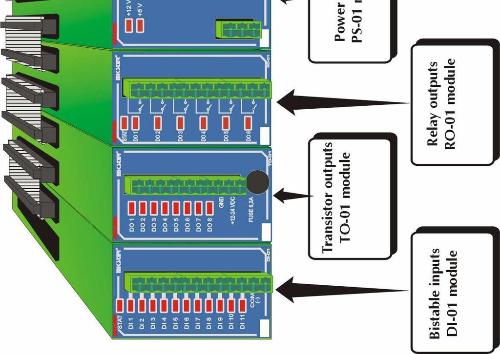
39 IV. INDU WRC DI-01MODULE 1. MODULE ASSEMBLING Module should be assembled on a rail and then connected with other modules by a belt. 2. MODULE FUNCTIONS DI-01 module is a bistable input module, which serves for controlling input signals (e.g. failure control). 3. FIGURE
40 4. TECHNICAL DATA POWER SUPPLY: 5 V DC, 12 V DC CASING: Dimensions: 45x75x105 mm for assembling on a rail TS 35 EG45 from the Phoenix Contact Company PROTECTION DEGREE: IP 30 TEMPERATURE: Storage: C Operation: C DISPLAY: KEYBOARD: STATE SIGNALLISATION: LED diode for each input, LED diode - status BISTABLE OUTPUTS: ANALOG OUTPUTS: 4 outputs ±10V, fun-out ±5mA ANALOG INPUTS: DIGITAL INPUTS: COMMUNICATION: 11 inputs 24V (direct or alternating) logic levels: V law high Communication bus to other modules
41 V. INDU WRC RO-01 MODULE 1. MODULE ASSEMBLING Module should be assembled on a rail and then connected with other modules by a belt. 2. MODULE FUNCTIONS Module serves for controlling by means of relay outputs. fan-out of a single output: 4A. Maximum 6 RO-01 modules can be connected to the system. Note: cards of the same type must have different addresses! (Altogether 32 outputs can be connected to the system RO-01 and TO-01 can be connected) RO-01 = 6 outputs TO-01 = 8 outputs 3.FIGURE
42 4. TECHNICAL DATA POWER SUPPLY: 5 V DC, 12 V DC CASING: Dimensions: 45x75x105 mm for assembling on a rail TS 35 EG45 from the Phoenix Contact Company PROTECTION DEGREE: IP 30 TEMPERATURE: Storage: C Operation: C DISPLAY: KEYBOARD: STATE SIGNALLISATION: BISTABLE OUTPUTS: ANALOG OUTPUTS: ANALOG INPUTS: DIGITAL INPUTS: COMMUNICATION: LED diode for each output, LED diode status 6 relay outputs fan-out: - 4A 230 V AC - 4A 24 V DC Communication bus to other modules 5. Cards addressing in the system: Output no 1 for the panel is the first output of the card with the lowest address. Note: cards of the same type must have different addresses! Address:

43 VI. INDU WRC TO-01 MODULE 1. MODULE ASSEMBLING Module should be assembled on a rail and then connected with other modules by a belt. 2. MODULE FUNCTION Module serves for controlling by means of transistor outputs. Fun-out of a single output 0.8A, total current of all outputs < 6.3A. Maximum 4 TO-01 modules can be connected to the system. Note: cards of the same type must have different addresses! (Altogether 32 outputs can be connected to the system RO-01 and TO-01 can be connected) RO-01 = 6 outputs TO-01 = 8 outputs 3. FIGURE
44 4. TECHNICAL DATA POWER SUPPLY: 5 V DC, 12 V DC CASING: Dimensions: 45x75x105 mm for assembling on a rail TS 35 EG45 from the Phoenix Contact Company PROTECTION DEGREE: IP 30 TEMPERATURE: Storage: C Operation: C DISPLAY: KEYBOARD: STATE SIGNALLISATION: BISTABLE OUTPUTS: ANALOG OUTPUTS: ANALOG INPUTS: DIGITAL INPUTS: COMMUNICATION: LED diode for each output, LED diode status 8 transistor outputs fun-out: - 0.8A total current for all outputs < 6.3A Communication bus to other modules 5. Cards addressing in the system: Output no 1 for the panel is the first output of the card with the lowest address. Note: cards of the same type must have different addresses! Address:
45 VII. INDU WRC COM-01 MODULE 1. MODULE ASSEMBLING Module should be assembled on a rail and then connected with other modules by a belt. 2. MODULE FUNCTION The module is used for communication between the INDU WRC set and the PC. Apart from storing the recordings the module enables readout of the set technological process parameters and values measured by controller s modules. Only one COM-01 module can be connected to the system. 3. FIGURE
46 4. TECHNICAL DATA POWER SUPPLY: 5 V DC, 12 V DC CASING: Dimensions: 45x75x105 mm for assembling on a rail TS 35 EG45 from the Phoenix Contact Company PROTECTION DEGREE: IP 30 TEMPERATURE: Storage: C Operation: C DISPLAY: KEYBOARD: STATE SIGNALLISATION: BISTABLE OUTPUTS: ANALOG OUTPUTS: ANALOG INPUTS: DIGITAL INPUTS: COMMUNICATION: 7 segments 7 segments LED diode RS-485 Communication bus to other modules
47 VIII. INDU WRC PS-01 MODULE 1. MODULE ASSEMBLING Module should be assembled on a rail and then connected with other modules by a belt. 2. MODULE FUNCTION The module is used for supplying the INDU WRC controller. It is supplied by 24V AC. Only one PS-01 module can be connected to the system. 3.FIGURE
48 4. TECHNICAL DATA POWER SUPPLY: 24V AC CASING: Dimensions: 45x75x105 mm for assembling on a rail TS 35 EG45 from the Phoenix Contact Company PROTECTION DEGREE: IP 30 TEMPERATURE: Storage: C Operation: C DISPLAY: KEYBOARD: STATE SIGNALLISATION: BISTABLE OUTPUTS: ANALOG OUTPUTS: ANALOG INPUTS: DIGITAL INPUTS: COMMUNICATION: LED Diode for 5V LED Diode for 12V Communication bus to other modules

49 Fig. Modules connection
RITZ / Turbine controls DISPLAY
 RITZ / Turbine controls DISPLAY CANCEL EXIT OK MENU F1 F2 F3 F4 The control/display unit has a CPU, an LCD display and 8 keys. 2 LEDs also display particular operational conditions (e.g. plant ON, faults,
vacon nx ac drives brake chopper unit (bcu) application user s manual
 application user s manual") vacon nx ac drives brake chopper unit (bcu) application user s manual 2 vacon Introduction Vacon Brake Chopper Unit application INDEX Document code: DPD01565A Software code: ABFIFF01V113 Date: 27.3.2014
vacon nx ac drives brake chopper unit (bcu) application user s manual 2 vacon Introduction Vacon Brake Chopper Unit application INDEX Document code: DPD01565A Software code: ABFIFF01V113 Date: 27.3.2014
Dryer. M720 Programming and Operation Manual. July 15, 2015 Revision 1.51
 Dryer M720 Programming and Operation Manual July 15, 2015 Revision 1.51 Contents 1 Important Safety Information 1 1.1 FOR YOUR SAFETY - CAUTION!............................. 1 2 Control Overview 2 2.1
INSTRUCTIONS FOR USING THE CONTROL PANEL
 DIGIT SED ELECTRONIC CONTROLLER WITH LCD DISPLAY 1.09.370E 10.01.2007 VALLOX These instructions replace and complement the instructions for use and maintenance of the following VALLOX units: VALLOX DIGIT
Mini Light Controller
 PX144 Mini Light Controller MANUAL R CONTENTS 1. General description... 1 2. Safety conditions... 1 3. Connection diagram... 2 4. Software Installation... 3 5. Controllers' PC software... 5 5.1. The connection
MiG2 CONTROLLERS. 2 & 4 Stage General Purpose Controllers, with Air-conditioning Facilities
 MiG2 CONTROLLERS 2 & 4 Stage General Purpose Controllers, with Air-conditioning Facilities The MiG2 controllers incorporate: 2 Inputs (Configurable as Resistive, 0 10V, 0 20mA or 4 20mA) 2 or 4 Relay Outputs
M15S OPERATION MANUAL
 M15S OPERATION MANUAL minikol ITALY www.minikol.com Index 1. Operation overview and general introduction... 1 2. Operation Modes... 2 2.1. Manual mode...2 2.2. Single mode...3 2.2.1. Setting target value...3
Product Manual SZ2141
 Product Manual SZ11 Refrigeration Controller Communicating Controls Description The SZ11 is a microprocessor-based refrigeration controller and alarm interface designed to control three coolers or freezers
DIN-RAIL EXPANDER int-iors_en 10/14
 INT-IORS INT-ORS DIN-RAIL EXPANDER int-iors_en 10/14 The INT-IORS expander enables the system to be expanded by 8 programmable wired zones and 8 programmable wired outputs. The INT-ORS expander enables
Monitoring technique. VARIMETER Voltage relay MK 9064N, MH 9064
 Monitoring technique VARIMETER Voltage relay MK 9064N, MH 9064 0269462 Your Advantages Preventive maintenance For better productivity Quicker fault locating Precise and reliable Min-, Max. value or window
ETHM-2. Ethernet Module. SATEL sp. z o.o. ul. Schuberta Gdańsk POLAND tel
 Ethernet Module ETHM-2 Firmware version 1.0 ethm2_en 09/08 SATEL sp. z o.o. ul. Schuberta 79 80-172 Gdańsk POLAND tel. + 48 58 320 94 00 info@satel.pl www.satel.pl SATEL's goal is to continually improve
GPRS-T1. Monitoring Converter. SATEL sp. z o.o. ul. Schuberta Gdańsk POLAND tel
 Monitoring Converter GPRS-T1 Program version 1.01 gprs-t1_en 04/09 SATEL sp. z o.o. ul. Schuberta 79 80-172 Gdańsk POLAND tel. + 48 58 320 94 00 info@satel.pl www.satel.pl WARNINGS The module should only
FCU-4 FAN COIL CONTROLLER
 FCU-4 FAN COIL CONTROLLER BACnet Enabled Description The FCU-4 is designed to provide complete control of fan coil units. The FCU-4 incorporates all the inputs and outputs to ensure that this advanced
isma-b-fcu FCU Hardware User Manual Global Control 5 Sp. z o.o. Warsaw, Poland
 isma-b-fcu User Manual FCU Hardware Global Control 5 Sp. z o.o. Warsaw, Poland www.gc5.pl Table of contents 1 Introduction 3 1.1 Document change log 3 1.2 Safety rules 3 1.3 Technical specifications 4
PADPULS2 M-BUS Pulse Input Modules
 Product sheet MT8.23 Meter Type PADPULS2 PADPULS2 M-BUS Pulse Input Modules The M-PADPULS series of devices connects meters with contact output to the M-Bus system. This is a simple and flexible solution
GPRS/SMS Reporting Module GPRS-T2
 GPRS/SMS Reporting Module GPRS-T2 Program version 2.01 gprs-t2_en 11/11 SATEL sp. z o.o. ul. Schuberta 79 80-172 Gdańsk POLAND tel. + 48 58 320 94 00 info@satel.pl www.satel.eu WARNINGS The module should
MXIO. Compact I/O module. Summary. Application Compact I/O module for data acquisition and HVAC control systems. Function
 MXIO Compact I/O module Summary The MXIO multiple I/O compact module is a microprocessor-controlled, communicative module with the I/O mix optimized for larger HVAC control applications. The module uses
TC-11 MULTIFUNCTIONAL TIME RELAY (TIMER) 1.0 version
 1.0 version") TC11 MULTIFUNCTIONAL TIME RELAY (TIMER) 1.0 version 1. SPECIFICATIONS. Digital input: Input signal: Output: Work mode: Display and time unit setting method: Measuring time accuracy: ±0,1% Power supply:
TC11 MULTIFUNCTIONAL TIME RELAY (TIMER) 1.0 version 1. SPECIFICATIONS. Digital input: Input signal: Output: Work mode: Display and time unit setting method: Measuring time accuracy: ±0,1% Power supply:
INT-KSG Keypad Quick user s guide
 INT-KSG Keypad Quick user s guide Firmware version 1.02 int-ksg_u_en 01/13 SATEL sp. z o.o. ul. Schuberta 79 80-172 Gdańsk POLAND tel. + 48 58 320 94 00 info@satel.pl www.satel.eu WARNINGS Please read
User Guide PC tool GDIR.danfoss.com
 User Guide PC tool Software for addressing, calibration and parameterization of Basic, Premium and Heavy Duty gas detection units and gas detection controller configuration GDIR.danfoss.com Contents Page
GRUNDFOS INSTRUCTIONS. Control MPC. Installation and operating instructions
 GRUNDFOS INSTRUCTIONS Control MPC Installation and operating instructions English (GB) English (GB) Installation and operating instructions Original installation and operating instructions CONTENTS Page
Supply voltage. Input current. Encoder supply. Memory SIMATIC S7-200, CPU 221 COMPACT UNIT, DC POWER SUPPLY 6 DI DC/4 DO DC, 4 KB CODE/2 KB DATA,
 Data sheet SIMATIC S7-200, CPU 221 COMPACT UNIT, DC POWER SUPPLY 6 DI DC/4 DO DC, 4 KB CODE/2 KB DATA, Supply voltage Rated value (DC) 24 V DC Load voltage L+ Rated value (DC) permissible range, lower
RWD32S Software Tool. Operating Instructions. CE1U3344en Building Technologies
 RWD32S Software Tool Operating Instructions CE1U3344en 25.06.2009 Building Technologies Siemens Switzerland Ltd Industry Sector Building Technologies Division International Headquarters HVAC Products Gubelstrasse
STRA-17 Room controller. Installation and maintenance manual. Content
 Content Installation preparations... Wiring diagram...3 Display handling...5 Technical data...6 Configuration...7 Operating modes...7 Controller modes...7 Activation operating modes...7 Control states...8
FCU-4 FAN COIL CONTROLLER
 FCU-4 FAN COIL CONTROLLER BACnet Enabled Description The FCU-4 is designed to provide complete control of fan coil units. The FCU-4 incorporates all the inputs and outputs to ensure that this advanced
Supply voltage. Input current. Encoder supply. Memory
 Data sheet SIMATIC S7-200, CPU 224XP COMPACT UNIT, DC POWER SUPPLY 14 DI DC/10 DO DC, 2 AI, 1 AO 12/16 KB CODE/10 KB DATA, 2 PPI/FREEPORT PORTS Supply voltage Rated value (DC) 24 V DC Load voltage L+ Rated
Operating Instructions
 33CS Comfort System Software CONTENTS Page GENERAL...1 OPERATION...1-11 Start-Up...1 Main Menu...2 CURSOR MOVEMENT AND FUNCTION SELECTION Initial Setup and Configuration...3 BASIC MODE EXPERT MODE MODEM
INT-TSI Brief User Manual
 int-tsi_u_en 03/15 Keypad INT-TSI Brief User Manual SATEL sp. z o.o. ul. Budowlanych 66 80-298 Gdańsk POLAND tel. 58 320 94 00 info@satel.pl www.satel.eu Firmware version 1.04 WARNINGS Please read this
LC502 control unit for MonoFlex single-line centralized lubrication systems. Operating instructions. Version 02
 LC50 control unit for MonoFlex single-line centralized lubrication systems Operating instructions Version 0 Page Operating instructions. Display and control elements of control screen. LC50 control screen.
DIGITAL DISPLAY. for Industry Applications. Series WAY-SSI. Key-Features:
 DIGITAL DISPLAY for Industry Applications Series WAY-SSI Key-Features: Content: Technical Data.2 Technical Drawing...2 Electrical Connection...3 Description...4 Order Code & Accessories...6 - WAY-SSI-S:
Pre-programmed room controller with display and communication
 revision 10 2017 RC-C3DOC Pre-programmed room controller with display and communication RC-C3DOC is a complete pre-programmed room controller from the Regio Midi series intended to control heating, cooling
Primus 96 advanced / Primus 96 advanced Gradient
 Primus 96 advanced / Primus 96 advanced Gradient Innovative PCR-Technology Instruction manual Table of Contents: 1. Operating elements of the Primus 96 advanced... 1 2. Installation of the Primus 96 advanced...
ZCM-12, ZCM-12P/U TIME PROGRAMMER WEEK S, DOUBLE CHANNEL
 ZCM-12, ZCM-12P/U TIME PROGRAMMER WEEK S, DOUBLE CHANNEL INSTRUCTION MANUAL ZAMEL Sp. z o.o. ul. Zielona 27, 43-200 Pszczyna, Poland Tel. +48 (32) 210 46 65, Fax +48 (32) 210 80 04 www.zamelcet.com, e-mail:
Characteristics and functioning
 Characteristics and functioning 1/27 enod4-c Characteristics and functioning NU-eNod4C-ETH-E-1014_216706-A 1 ENOD4 PRODUCT RANGE... 4 1.1 General presentation... 4 1.2 Versions and options... 4 1.2.1 Versions...
EVF305 Product specifications - Version 1.02 EVCO S.p.A. Evco S.p.A. Product specifications EVF305
 Evco S.p.A. Product specifications EVF305 Digital controllers for the management of the rotisserie with capacitive type user interface Drawn-up by Name and surname Date November 2012 page 1 of 14 1. REVISIONS
OPT2011. High-performance distance sensor. Operating Instructions
 OPT2011 High-performance distance sensor Operating Instructions Status: 15/07/2013 2 Table of Contents 1. Use for Intended Purpose 4 2. Safety Precautions 4 2.1. Safety Precautions 4 2.2. Laser/LED warning
DIGITAL DISPLAY. for Industry Applications. Series WAY-D. Key-Features:
 DIGITAL DISPLAY for Industry Applications Series WAY-D Key-Features: Content: Technical Data.2 Technical Drawing...2 Electrical Connection...3 Programming...5 Control s...6 Order Code & Accessories...7
PROGRAM BASED EVENT CONVERTER SMET-SERVER
 PROGRAM BASED EVENT CONVERTER SMET-SERVER USER MANUAL Program version 1.01 smet-server_en 03/13 The SATEL's goal is to continually upgrade the quality of its products, which may result in alterations of
FG-7000L Digital Force Gauge Operation Manual
 FG-7000L Digital Force Gauge Operation Manual Operators should wear protection such as a mask and gloves in case pieces or components break away from the unit under test. Whether the unit is ON or OFF,
MODBus RTU for AKOCAM and AKOPRO controllers
 156FHF02 Ed 03 GB MODBus RTU for AKOCAM and AKOPRO controllers 1. INTRODUCTION The purpose of this document is to describe to the user the functioning of the MODBus RTU series communications protocol implemented
GSM communicator GD-06 Allegro Complete manual
 GSM communicator GD-06 Allegro Complete manual The GD-06 ALLEGRO is a universal GSM dialer and controller. It can be used for both home and industrial automation purposes, for security applications or
UNIVERSAL EXPANDER FOR CARD / CHIP READERS INT-R. 1. Features. 2. Installation and start-up
 UNIVERSAL EXPANDER FOR CARD / CHIP READERS INT-R int-r_en 09/11 The INT-R expander interfaces with the INTEGRA and CA-64 alarm control panels, replacing the previously offered CA-64 SR and CA-64 DR expanders.
TEMPERATURE AND HUMIDITY REGISTERING DEVICE MANUAL
 Logger Termio+ TEMPERATURE AND HUMIDITY REGISTERING DEVICE MANUAL 1 CONTENT Logger...1 Termio+... 1 TEMPERATURE AND HUMIDITY... 1 2 Intended use Termio Logger is designed to measure and register temperature
4-step Chiller and Heat Pump Controller
 4-step Chiller and Heat Pump Controller Technical Data Sheet GENERAL DESCRIPTION MODELS CODE MODEL DESCRIPTION MW324000 ECH 420 HEAT PUMP WITH 4 STEPS/ 2 CIRCUITS + MODBUS MW324005 ECH 420/V WITH SCREW
3690 N.W. 53rd Street Fort Lauderdale, FL SC-2124 SC-2124M. 24 Channel Universal Scanner. Installation and Operation Manual P/N 145F-11902
 3690 N.W. 53rd Street Fort Lauderdale, FL 33309 SC-2124 SC-2124M 24 Channel Universal Scanner Installation and Operation Manual P/N 145F-11902 Rev. 3.30 (c) Copyright 2000, Dynalco Controls All Rights
INT-KSG Keypad Quick user s guide
 INT-KSG Keypad Quick user s guide Firmware version 1.00 int-ksg_u_en 08/10 SATEL sp. z o.o. ul. Schuberta 79 80-172 Gdańsk POLAND tel. + 48 58 320 94 00 info@satel.pl www.satel.eu WARNINGS Please read
Service Bulletin SB685. Date: 8/18/2017 TriPac EVOLUTION Communications Update Bulletin Location: TSA Info Central\Service Bulletins
 Service Bulletin SB685 Date: 8/18/2017 Subject: TriPac EVOLUTION Communications Update Bulletin Location: TSA Info Central\Service Bulletins Units: All TriPac EVOLUTION Summary: This bulletin updates and
SHIMPO INSTRUMENTS. FG-7000T Digital Torque Gauge Operation Manual
 FG-7000T Digital Torque Gauge Operation Manual SHIMPO INSTRUMENTS Operators should wear protection such as a mask and gloves in case pieces or components break away from the unit under test. Whether the
ADC7520 SERIES. 1600W Battery Chargers and Power Supplies
 ADC7520 SERIES 1600W Battery Chargers and Power Supplies Wide output adjustment range 0 72VDC Analog control by external 0-5VDC voltage Temp.comp charging, sense as on option Power fail relay alarm Master-Slave
K-BUS R. Dimming Actuators. User manual-ver. 4 KA/D KA/D KA/D KA/D 04.T1.1 ADTV-04/16.1 KA/D 04.L1.1 ADLD-04/
 Guangzhou Video-star Electronics Industrial Co., Ltd K-BUS R Dimming Actuators User manual-ver. 4 KA/D 0103.1 KA/D 0203.1 KA/D 0403.1 KA/D 04.T1.1 ADTV-04/16.1 KA/D 04.L1.1 ADLD-04/03.1...... KNX/EIB Intelligent
Operating instructions. Relay adapter, analog ALMEMO ZA 8006-RTA4 V
 Operating instructions Relay adapter, analog ALMEMO ZA 8006-RTA4 V1.0 04.03.2008 www.ahlborn.com 1. Operating controls 1. OPERATING CONTROLS Rear of device (6) Battery compartment 3 AA alkaline-manganese
JUMO ctron 04/08/16. Compact controller with timer and ramp function. B Interface Description Modbus /
 JUMO ctron 04/08/16 Compact controller with timer and ramp function 702071 702072 702074 B 70.2070.2.0 Interface Description Modbus 2008-08-11/00492538 Contents 1 Introduction 5 1.1 Preface... 5 1.2 Typographical
CONDUCTOR W4. Installation instruction for W4.1 and W To mount the controller. Controller. Mounting on a DIN rail
 CONDUCTOR W Installation instruction for W. and W. 00 Controller To mount the controller. Mounting on a DIN rail Figure. Overview of the Controller. Pos. Product marking. Pos. Termination resistance. =
DIGITAL DISPLAY. for Industry Applications. Serie REX-D. Key-Features:
 DIGITAL DISPLAY for Industry Applications Serie REX-D Key-Features: Content: 01.07.16 - REX-D-X345: only display - REX-D-X347: display with two presets and switching out puts - REX-D-X348: Display with
USER MANUAL V1.1. Setpoint unit 2022Setp
 USER MANUAL 0.4.005 V. Setpoint unit 0Setp INTRODUCTION 0Setp is a special edition of Nokeval 0 multi-input indicator. It is available in wall-mounted 800 enclosure or in a /8 DIN panel enclosure. Normally
Application program: description and examples
 F a n C o i l U n i t C o n t r o l l e r F a n C o i l 4 9 5 5 1 Application program: description and examples Woertz AG Electrotechnical accessories, installation systems Hofackerstrasse 47, P.O. Box
Product Manual SZ2144
 Product Manual SZ1 Refrigeration Monitor Communicating Controls Description The SZ1 is a microprocessor-based refrigeration monitor and alarm interface designed to monitor up to six coolers or freezers.
UDC 1000 and UDC 1500 MICRO-PRO SERIES UNIVERSAL DIGITAL CONTROLLERS
 UDC 1000 and UDC 1500 MICRO-PRO SERIES UNIVERSAL DIGITAL CONTROLLERS EN0I-6041 12/99 PRODUCT SPECIFICATION SHEET OVERVIEW The UDC 1000 and UDC 1500 are microprocessor-based 1/16 DIN and 1/8 DIN controllers
Defining Points. Introduction
 M-Series Workstation with Companion/Facilitator Manual 9-1 Chapter 9 Defining Points Introduction This chapter explains how to define software points. Points are software representations of input and output
RAMSES D GB F NL. Installation and operating instructions Room thermostat. RAMSES 832 top2
 309 358 04 RAMSES RAMSES 811 top2 RAMSES 831 top2 811 9 132 831 9 132 RAMSES 812 top2 RAMSES 832 top2 812 0 132 832 0 132 GB Installation and operating instructions Room thermostat D GB F E I NL RAMSES
AC500-eCo: your PLC from ABB Unique scalable concept, optimal costs... Change for more!
 AC500-eCo: your PLC from ABB Unique scalable concept, optimal costs... Change for more! How can the AC500-eCo contribute more to your success? Return on your investment is one of the key benefits with
RADIO REMOTE CONTROLLER SET RE-4K
 RADIO REMOTE CONTROLLER SET RE-4K re4k_en 09/11 The RE-4K four-channel radio remote controller set enables electrical equipment to be remotely controlled by means of radio transmitters (remote keyfobs).
MCX08M2 Programmable controller
 Data sheet MCX08M2 Programmable controller MCX08M2 is an electronic controller that holds all the typical functionalities of MCX controllers in the compact size of 8 DIN modules: programmability connection
AMC 8 & IOC 8T. Analog Monitoring Card Type AMC 8 and Input / Output Card Type IOC 8T FEATURES
 Analog Monitoring Card Type AMC 8 and Input / Output Card Type IOC 8T FEATURES Two cards providing 8 channels of temperature and process monitoring for VM 600 systems 8 channels of software selectable
CPU 224. The compact high-performance CPU With 24 inputs/outputs on board Expandable with up to 7 expansion modules Design
 CPU 224 The compact high-performance CPU With 24 inputs/outputs on board Expandable with up to 7 expansion modules Design The CPU 224 is equipped with the following: Integral 24 V encoder/load current
Rev Cutler-Hammer Smart Breaker Panel Control Manual
 026-70 Rev 0 6-0-03 Cutler-Hammer Smart Breaker Panel Control Manual 640 Airport Road, Suite 04 Kennesaw, GA 3044 Phone: (770) 425-2724 Fax: (770) 425-939 ALL RIGHTS RESERVED. The information contained
SD1. Differential Controller. Operating and Installation Instructions F2 72.3
 SD1 Differential Controller Operating and Installation Instructions F2 72.3 i Please follow the safety information and read these Instructions carefully before putting the system into operation. Safety
Compressor Controller MAM 890
 Compressor Controller MAM 890 OPERATION MANUAL Revision 1.0 04.08.2017 Notice Please read all the operation manual before operating the set and keep this manual for further reference. Installation of MAM
A2000 Multifunctional Power Meter
 3-348-980-03 3/12.99 Capable of communications via Profibus-DP, LONWORKS interface or RS 485 interface (depending upon model) Measurement of current, voltage, active, reactive and apparent power, power
The Carel driver connects to a network of Carel air-conditioning and refrigeration packaged controls. Available for Commander and ObSys.
 The Carel Driver The Carel driver connects to a network of Carel air-conditioning and refrigeration packaged controls. Available for Commander and ObSys. This document relates to Carel driver version 2.0
Quick Start Guide Cutler-Hammer SVX9000 Drives from Eaton Corporation CONTENT STEP 1 Keypad Operation Overview STEP 2 Standard Wiring Diagrams and
 Quick Start Guide Cutler-Hammer SVX9000 Drives from Eaton Corporation CONTENT STEP 1 Keypad Operation Overview STEP 2 Standard Wiring Diagrams and Connections STEP 3 Start-Up Wizard STEP 4 Operating and
Operation Manual for Multifunctional Data Logger. HUATO Electronic Co., LTD.
 Operation Manual for Multifunctional Data Logger HUATO Electronic Co., LTD. Contents Contents...2 1. Introduction...1 1.1 Features...1 1.2 Structure for S210 multifunctional data logger...1 1.3 LCD symbols
TAC Xenta 121-FC Programmable Fan Coil Application
 TAC Vista TAC Xenta 121-FC Programmable Fan Coil Application TAC Xenta 121-FC is an easily programmable controller intended for both 2-pipe and 4-pipe applications, with or without re-heat. It can be configured
DS-4483 Standard Logger Program Quick Reference For Software Version: 4.06
 DS-4483 Standard Logger Program Quick Reference For Software Version: 4.06 Requires Firmware Version: VL/2.17+ Revision History: Version 1.00 02 February 2004 Preliminary release version Version 4.01 21
I-7520: RS-232 to RS-485. Input: RS-232 protocol Output:RS-485/RS-422 Speed: Self Tuner 'inside, auto switching baud rate, 300~ BPS
 I-7520 RS-232 to RS-485 Converter I-7510 RS-485 Repeater RS-232 RS-485 I-7000 SERIES Common Specifications Isolation voltage: 3000VDC Speed: 1200, 2400, 4800, 9600, 19200, 38400, 57600, 115000 Dual watchdog
Multi-instrument Communication, MIC-2 MKII DIN Quick Start Guide
 Multi-instrument Communication, MIC-2 MKII DIN Quick Start Guide Warnings and legal information Installation and terminals Communication I/O options Alarming Utility software More information Specifications
Operating instructions for RAMSES 811 top2_812 top2 and RAMSES 831 top2_832 top2
 Operating instructions for RAMSES 811 top2_812 top2 and RAMSES 831 top2_832 top2 Dear client, if you have the newer device, please use page 1 to 33 RAMSES RAMSES 811 top2 RAMSES 831 top2 8119132 8319132
Installation & Operation
 LED Readout Installation & Operation WARRANTY Accurate Technology, Inc. warrants the ProScale Systems against defective parts and workmanship for 1 year commencing from the date of original purchase. Upon
LineMaster 200. Continuous-line recorder. Parameter setting instructions 42/43-28 EN Rev. 03
 LineMaster 200 Continuous-line recorder setting instructions 42/43-28 EN Rev. 03 Contents definition sequence Page Removing the chart unit... 3 Display and operator control unit... 3 Password... 4 -definition
AI-917-A0. Analogue Input Module (4x 0-20 ma)
") General Specifications GS48D17A00-00E-N AI-917-A0 Analogue Input Module (4x 0-20 ma) GENERAL Figure 1 This module has four analogue inputs and four logic pulse outputs. AI-917-A0 Analogue Input Module
General Specifications GS48D17A00-00E-N AI-917-A0 Analogue Input Module (4x 0-20 ma) GENERAL Figure 1 This module has four analogue inputs and four logic pulse outputs. AI-917-A0 Analogue Input Module
U90 Ladder Software Manual. Version 3.50, 6/03
 U90 Ladder Software Manual Version 3.50, 6/03 Table Of Contents Welcome to U90 Ladder... 1 Program Editors... 1 Project Navigation Tree...1 Browse Sequences...1 Printing Documentation...2 Interface Language...
Supplementary operating instructions for your air curtain system Controller TMC 500
 Supplementary operating instructions for your air curtain system Controller TMC 500 (Translation of the original) Serial number: Year: Please quote this number when contacting customer service! Date 08.04.2016
HI-POT TESTER. User s Manual
 HI-POT TESTER 7620 User s Manual Contents 1. Before Use... 1.1Electric Shock Avoidance... 4 1.2 Grounding... 4 1.3 AC Power Supply... 4 1.4 Connecting Test Leads... 4 1.5 Warm Up... 4 1.6 External Control...
Buffered Power Supply PS-30DR v1.0
 Roger Access Control System Buffered Power Supply PS-30DR v1.0 Document version: Rev. C Firmware: 1.0.4 1. PRODUCT DESCRIPTION The PS-30DR is dedicated for electronic equipment which require 12VDC buffered
TR150 DRIVE STANDARD FEATURES
 TR150 DRIVE STANDARD FEATURES The TR150 Drive The TR150 Drive Series is a microprocessor-based, high frequency IGBT-based, PWM AC drive with control functions and software designed solely for the unique
EY-EM : Remote I/O module, ecolink
 EY-EM 510...512: Remote I/O module, ecolink510...512 How energy efficiency is improved Optimum adjustment to applications by means of module technology. Reduction in wiring Features Part of the SAUTER
Operating Manual version 1.2
 VEHICLE TEMPERATURE AND HUMIDITY RECORDER Operating Manual version 1.2 Sp. z o.o. 41-250 Czeladź ul. Wojkowicka 21 tel. +48 32 763 77 77 fax. +48 32 763 75 94 www.mikster.pl mikster@mikster.pl Table of
EC700. Pulses concentrator. User instructions
 EC700 Pulses concentrator User instructions Contents Hazards and warning... 3 Initial checks... 3 Introduction... 4 Jbus/Modbus Communication... 5 Installation... 6 Configuration... 9 Use... 9 Programming...
Multi-instrument Communication, MIC-2 MKII DIN Quick Start Guide
 Multi-instrument Communication, MIC-2 MKII DIN Quick Start Guide Warnings and legal information Installation and terminals Communication I/O options Alarming Utility software More information Specifications
Instruction Manual CTC-1
 Troubleshooting & Specs CTC-1 Amps / Volts requirements Min / Max operating temperature Min / Max operating Humidity Temperature Measurement range Temperature Accuracy CO2 sensor type CO2 Measurement range
Strain Gauge Converter
 EN Z-SG General Description Module Z-SG is a strain gauge signal converter. Measurements taken using the 6-wires or 4-wires technique are available through Modbus-RTU serial protocol or the analog output.
Clear Benefits of the KRAL Electronic.
 Clear Benefits of the KRAL Electronic. Coordinated to the flowmeters and their applications. Users of conventional universal display units often cannot make use of their device s options. There is often
EBS-6200 PRINTER BASIC MANUAL VERSION: #1.1. Copyright 2009 EBS Ink-Jet Systeme All rights reserved. Changes may apply.
 EBS-6200 PRINTER BASIC MANUAL ERSION: 20091216#1.1 Copyright 2009 EBS Ink-Jet Systeme All rights reserved. Changes may apply. TABLE OF CONTENTS 1. General Information... 3 2. Printer Elements... 3 3. Safety
GmbH, Stettiner Str. 38, D Paderborn
 AnDi 1 to AnDi 4 A/D Converter for M-Bus (Valid from M-Bus generation: $31) Art. no. MB AnDi 1 Art. no. MB AnDi 2 Art. no. MB AnDi 3 Art. no. MB AnDi 4 1 channel A/D converter for M-Bus 2 channel A/D converter
Datasheet RCUXXYY EAE KNX Room Control Unit RCUXXYY DT R1.0. General Description. EAE Technology Page 1/10
 General Description Room Control Unit RCU Series are designed as an all in one product for different room layouts such as apartments, hotel rooms, hospitals and residences. Available versions of EAE RCU
SERVO-DRIVE. PROGRAMMABLE STEP MOTOR CONTROLLER R ETH and R ETH. Manual Ver. 05
 SERVO-DRIVE PROGRAMMABLE STEP MOTOR CONTROLLER R272-42-ETH and R272-80-ETH Manual Ver. 05 2018 1. Product designation Programmable step motor controller R272-42-ETH is designed to operate with hybrid two
PLC-24V10AL(-PT/-TH) Quick Start Manual (Rev.1.10)
 Quick Start Manual (Rev.1.10)") TEC (Peltier) Controller PLC-24V10AL(-PT/-TH) Quick Start Manual (Rev.1.10) Thank you for purchasing the TEC (Peltier) Controller PLC-24V10AL. Read these operating instructions carefully to ensure effective
TEC (Peltier) Controller PLC-24V10AL(-PT/-TH) Quick Start Manual (Rev.1.10) Thank you for purchasing the TEC (Peltier) Controller PLC-24V10AL. Read these operating instructions carefully to ensure effective
Measure & Control Temperature & CO2 levels with analog & digital I/O
 MADE IN OZ HTC-DIGITAL-LCD PROGRAMMABLE TEMPERATURE CONTROLLER c/w YEARLY PROGRAMMABLE TIME SWITCH COMPATIBLE WITH A WIDE RANGE OF SENSORS ROOM O/A WALL DUCT PIPE Use Features Measure & Control Temperature
GSM HOME SECURITY SYSTEM
 Cell /Mobile phone home security system GSM HOME SECURITY SYSTEM Model : BS120 TABLE OF CONTENTS 1. FEATURES... 1 2. APPLICATION... 2 3. SPECIFICATIONS... 3 4. FRONT PANEL & LAYOUT DESCRIPTION...6 5. BASIC
1. Features. 2. Installation KNX INTEGRATION MODULE INT-KNX
 KNX INTEGRATION MODULE INT-KNX int-knx_en 09/11 The INT-KNX module integrates the INTEGRA alarm system with the KNX system, so the control panel can control the actuators connected to the KNX bus, and