SVM F4. Node. Calculator. Installation Guide
|
|
|
- Margaret Anderson
- 5 years ago
- Views:
Transcription

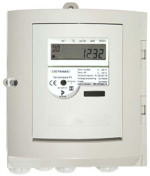
1 SVM F4 Calculator Installation Guide Node

2 Installation guide for F4 For further information, also cf. the F4 manual Delivery The calculator is normally delivered in transport mode. In this mode only the system clock is active and no measurements are done. Transport mode is indicated by no in the upper left corner of the display. Prior to the installation the calculator must be activated, by pressing the Push-button in approximately 5 seconds the meter will normally go in to INIT -mode. In INIT -mode one can set the meter, see manual for further instructions. When exiting the INIT -mode the meter will enter normal mode ( operating mode ), the display will indicate 10 in the upper left corner. Connections Table 1 and Figure 1 shows how to connect the calculator. Mounting F4 is constructed for wall mounting. Terminal no according to EN1434 Signal descriptor 1 High Temp. sensor * 2 High Temp. sensor * 3 Low Temp. sensor * 4 Low Temp. sensor * 5 High Temp. sensor 6 High Temp. sensor 7 Low Temp. sensor 8 Low Temp. sensor 10 Flow sensor (+) 11 Flow sensor (-) 24 M-Bus interface 25 M-Bus interface 60 SIOX ** 61 SIOX ** Table 1, * Only used with 4-Wired method ** Only when option board SIOX is installed in card slot A. only A1 and A2 are connected to the SIOX loop Fig 5.2, Numbering of terminal according to EN1434, (numbering from left to right).

3 Circuit board F4 Option board slots F4 marking 2 Power ON/OFF, remove 4-Wire cables K2 and K3 for Power off Save data button, short circuit to store data Connection flow sensor. Flow sensor must be galvanic insulated. 2/4 Wire, jumper setting Connection of alarm output: D1 = + D2 = GND Fig. 2, Main circuit board F4 When common earth can be joined by the calculator through the pulse inputs, pulse outputs, flow input, temperature these inputs/ outputs must be galvanic separated. See F4 manual Zero Sequence current for more information.
4 Connection/handling Only option board marked with 2 may be installed on the F4. Connection flow sensors, temperature sensors and M-Bus See fig 1, mounting. The flow sensor must be galvanic isolated when using the calculator in M-Bus loop. See the F4 manual for more information. Pulse inputs IN 1 = + pulse input 1 IN 2 = + pulse input 2 IN = for both pulse inputs. ( jumpers are set according to markings on the main circuit board). Programming Warning: F4 may only be programmed with service program version 2.0 or higher Connection of mains The calculator is normally with mains supply. Connection of mains: Line to terminal marked L, neutral to terminal marked N and ground to terminal marked with ground symbol, see also fig.3 Pulse outputs UT 1 = + pulse output 1 UT 2 = + pulse output 2 UT = for both pulse outputs ( jumpers are set according to markings on the main circuit board). Alarm Connect + till terminal marked D1 and GND to D2. ( jumpers are set according to markings on the main circuit board). Save data By short circuiting the Save data the meter data are stored in a safe way. ( not all option board will store it s data upon this procedure). Power Off Remove the cables marked K2 and K3. Industrial applications When the F4 is being used in industrial applications or elsewhere with tough EMC conditions, the following recommendations must be observed to ensure a trouble-free operation of the calculator: Fig. 3, Connection board mains with back-up battery Use screened cables for the connection of temperature sensors. Connect the screen to the Ktterminal (terminal 11) in the calculator. On the temperature sensor end the screen should be left unconnected for best results. Install an option board for galvanic isolation of the M- Bus (FCR2 option board). When applicable, use a flow sensor with galvanic isolation.

5 Option board handling Extended functions can be added to the F4 meter by installing option boards. Only meters with mains power supply may be equipped with option boards. Check option board documentation for exceptions. Only option boards with the mark 2 may be used with the F4. See fig Only one (1) option board may be installed at the time, in order for the meter to recognize the option board. Option board installation procedure 1. Check option board, Marking 2 and which card slot can be used for option board and check correct jumper setting on option board, see table Save data, using save key to short circuit the Save data button 3. Disconnect flow sensor connections by removing one flow sensor cable connected to terminal. 4. Cut power to main circuit board, remove 4-Wire cables K2 and K3 connected to mains 5. Remove jumpers on slot (only if required, check with option board manual) 6. Check DIP switch settings on option board 7. Install the option board carefully, do not bend any terminal pins. (Only one option board may be installed at the time). 8. Turn power ON, by connecting 4-Wire cables K2 and K3. 9. Check LED LD3 on the option board is turned off, this indicates proper installation of option board. Follow the steps 3-9 for installation of additional option boards. Note; only one (1) option board may be installed at the time. 10. Connect flow sensor The option board may only be installed in assigned slots, please consult option board documentation for further information. Option board affects battery life expectancy please check with ABB Metering or option board documentation when using a meter only powered by batteries. DIP-Switch setting of option board Slot BY 1 BY 2 BY 3 A X B X C X X D X E X X F Service (X) X X Table 5.5, DIP-Switch setting of option board for card slots, X ON, OFF, (X) insignificant Not all option boards can be combined check documentation for more information. 2 LED, LD3 Fig. 5.1., Option board Fig 5.2, Mark 2 for F4 Option Boards DIP Switches Metrima AB Norra Stationsgatan 93 SE Stockholm Phone: Fax: info@metrima.se E /GSe
SVM F4. Calculator. Manual
 SVM F4 Calculator Manual Calculator F4 manual 1 GENERAL 4 1.1 Installation 4 1.2 Principle of energy measurement 5 1.2.1 Alternative naming 5 1.3 Calculator specifics 5 1.3.1 Monthly values 7 1.3.2 Account
ABB Drives. User s Manual. Analogue I/O Extension Module RAIO-01
 ABB Drives User s Manual Analogue I/O Extension Module RAIO-01 Analogue I/O Extension Module RAIO-01 User s Manual 3AFE 64484567 REV A EN EFFECTIVE: 1.2.2002 2002 ABB Oy. All Rights Reserved. Safety
ABB Drives. User s Manual. Digital I/O Extension Module RDIO-01
 ABB Drives User s Manual Digital I/O Extension Module RDIO-01 Digital I/O Extension Module RDIO-01 User s Manual 3AFE 64485733 REV B EN EFFECTIVE: 10.2.2003 2003 ABB Oy. All Rights Reserved. Safety Instructions
ABB Drives. User s Manual Modbus Adapter Module FMBA-01
 ABB Drives User s Manual Modbus Adapter Module FMBA-01 Modbus Adapter Module FMBA-01 User s Manual 3AFE68586704 REV A EN EFFECTIVE: 27.06.2005 2005 ABB Oy. All Rights Reserved. 5 Safety instructions
EA500. Installation Instructions Transponder
 EA500 EN Installation Instructions Transponder EA500 Installation Instructions 1.0 Overview EN 2 1.0 Overview The EA500 Transponder is the Security Escort module that provides communications between the
PTC/PT100 board 2.0 Option
 PTC/PT100 board 2.0 Option Instruction Manual - English PTC/PT100 board 2.0 Option Instruction Manual - English Document number: 01-3873-01 Edition: r1 Date of release: 2006-10-30 Copyright Emotron AB
Data sheet GCM MOD GMM EC.1 Communications module Modbus for GMM EC
 Data sheet GCM MOD GMM EC.1 Communications module Modbus for GMM EC ERP no.: 5206415 GCM MOD GMM EC.1 www.guentner.de Page 2 / 15 Contents 1 GCM MOD GMM EC.1...3 1.1 Functional description...3 1.2 Connections...
INSTALLATIONSANVISNING INSTALLATION MANUAL INSTALLATIONS ANLEITUNG MANUEL D INSTALLATION RD-48 LV/HV. RS-422/485 Repeater Répéteur RS-422/485
 LV/HV INSTALLATISANVISNING INSTALLATI MANUAL INSTALLATIS ANLEITUNG MANUEL D INSTALLATI Westermo Teleindustri AB 2004 REV. C Galvanic Isolation Transient Protection Balanced Transmission CE Approved RS-422/485
EL731 PROFIBUS INTERFACE
 Tel: +1-800-832-3873 E-mail: techline@littelfuse.com www.littelfuse.com/el731 EL731 PROFIBUS INTERFACE Revision 0-A-032816 Copyright 2016 Littelfuse Startco All rights reserved. Document Number: PM-1011-EN
ABB Drives. User s Manual. Modbus Adapter Module RMBA-01
 ABB Drives User s Manual Modbus Adapter Module RMBA-01 Modbus Adapter Module RMBA-01 User s Manual 3AFE 64498851 REV A EN EFFECTIVE: 1.3.2002 2002 ABB Oy. All Rights Reserved. Safety instructions Overview
Installation Instructions (KF-2000)
") VERSION 2005. 10 Installation Instructions (KF-2000) Keico Hightech, Inc. Installation Instructions KF-2000 Keico Hightech Ace Twin Tower I 12 th FL 212-1, Guro-Dong, Guro-Gu Phone +82-2-853-9000 Fax +82-2-830-7809
VERSION 2005. 10 Installation Instructions (KF-2000) Keico Hightech, Inc. Installation Instructions KF-2000 Keico Hightech Ace Twin Tower I 12 th FL 212-1, Guro-Dong, Guro-Gu Phone +82-2-853-9000 Fax +82-2-830-7809
Dual channel temperature logger with two voltage inputs 0-5V Instruction Manual
 LOGGER S0541 Dual channel temperature logger with two voltage inputs 0-5V Instruction Manual Instruction Manual for use of S0541 logger Instrument is designed for measurement and record of temperature
UC102 basic version with display and knob UC102BL version with display, knob and backlight UC102DK version without knob and display
 UC102 Communicative heating controller Summary UC102 is a communicative room heating controller with two inputs and one PWM output for control of a radiator or electrical heater. It can work autonomously,
IV-30 Operating Manual for Pulse Distributor Cassette with potential separation
 IV-30 Operating Manual for Pulse Distributor Cassette with potential separation Edition-/Rev.-Date: 09/08/2006 Document-/Rev.-No.: TR - EAK - BA - GB - 0093-02 Software version: - File name: TR-EAK-BA-GB-0093-02.DOC
DUAL LOOP DETECTOR WITH MODBUS COMMUNICATIONS
 LD220 DUAL LOOP DETECTOR WITH MODBUS COMMUNICATIONS USER MANUAL P.O.Box 24 STANFIELD 3613 SOUTH AFRICA Tel: +27 (031) 7028033 Fax: +27 (031) 7028041 Email: proconel@proconel.com Web: www.proconel.com 18/08/2005
COMFORT CONTROL CENTER SERVICE INSTRUCTIONS
 USA SERVICE OFFICE Dometic Corporation 2320 Industrial Parkway Elkhart, IN 46516 574-294-2511 CANADA Dometic Corporation 46 Zatonski, Unit 3 Brantford, ON N3T 5L8 CANADA 519-720-9578 For Service Center
M1600 Parallel Input / Output
 M1600 Parallel Input / Output Technical Documentation Eiserstraße 5 phone 05246/709-0 33415 Verl fax 05246/70980 Date : 8.8.94 Version : 2.0 Page 1 of 14 Table of Contents 1. Function Description Hardware...3
RTT2 ROOM TEMPERATURE SWITCH. Mounting and operating instructions
 Mounting and operating instructions Table of contents SAFETY AND PRECAUTIONS PRODUCT DESCRIPTION ARTICLE CODES INTENDED AREA OF USE TECHNICAL DATA STANDARDS OPERATIONAL DIAGRAMS WIRING AND CONNECTIONS
CA-A480-A Elevator Controller. Reference & Installation Manual
 CA-A480-A Elevator Controller Reference & Installation Manual TABLE OF CONTENTS INTRODUCTION.................................................................. 4 Introduction.............................................................................................
Creone AB Box 148 S Tranås SWEDEN Tel: +46(0) Fax: +46(0) Internet: All data
 Fax: +46(0) Internet: All data") INSTRUCTION MANUAL Keybox 9000 Basic Keybox 9000 System Keybox 9000 Expansion KeyWin Light Creone AB Box 148 S-573 22 Tranås SWEDEN Tel: +46(0)140-38 61 80 Fax: +46(0)140-38 61 89 E-mail: mailbox@creone.com
INSTRUCTION MANUAL Keybox 9000 Basic Keybox 9000 System Keybox 9000 Expansion KeyWin Light Creone AB Box 148 S-573 22 Tranås SWEDEN Tel: +46(0)140-38 61 80 Fax: +46(0)140-38 61 89 E-mail: mailbox@creone.com
Modem Installation and Networking Instructions
 Modem Installation and Networking Instructions P/N 36870 Rev F Introduction The following instructions cover connecting a phone line to an incoming phone source, installing a modem, and setting up a network
Expansion Module HZS 541-1S
 Expansion Module HZS 541-1S 12.10.2015 Page 1 System Description The external HZS 541-1S expansion module provides users of biomass heating systems with additional 230 V AC relay outputs, analog inputs
RТTH DUAL ROOM SWITCH
 DUAL ROOM SWITCH FOR TEMPERATURE AND RELATIVE HUMIDITY Mounting and operating instructions Table of contents SAFETY AND PRECAUTIONS PRODUCT DESCRIPTION ARTICLE CODES INTENDED AREA OF USE TECHNICAL DATA
StorEdge Wiring Guide & On Site Checklist for North America
 StorEdge Wiring Guide & On Site Checklist for North America This document is a battery wiring guide and contains an on-site checklist with steps for post-installation verification of a StorEdge system,
mark150s mark150/485s DDC controllers Summary
 mark150s mark150/485s DDC controllers Summary DDC (Direct digital control) controller mark150s and mark150/485s are free programmable process stations with ARM Cortex M4 processor and OS FreeRTOS. They
Advant OCS. The Compact and Cost Effective Advant Controller. Advant Controller 210. Open Control System
 Advant OCS Open Control System Advant Controller 210 The Compact and Cost Effective Advant Controller Advant Controller 210 is a small, cost-effective system belonging to the Advant Controller family.
Allen-Bradley Drives. Instructions. (For 6180 Industrial Computers)
") Instructions (For 6180 Industrial Computers) This document describes how to remove or install a Pentium processor in the 6180 Industrial Computer. Processor specifications are also provided. The processor
Instructions (For 6180 Industrial Computers) This document describes how to remove or install a Pentium processor in the 6180 Industrial Computer. Processor specifications are also provided. The processor
ABB Drives. User s Manual Pulse Encoder Interface Module MTAC-01
 ABB Drives User s Manual Pulse Encoder Interface Module MTAC-01 Pulse Encoder Interface Module MTAC-01 User s Manual 3AFE68591091 REV B EN EFFECTIVE: 04.04.2006 2006 ABB Oy. All Rights Reserved. 5 Safety
ADC7520 SERIES. 1600W Battery Chargers and Power Supplies
 ADC7520 SERIES 1600W Battery Chargers and Power Supplies Wide output adjustment range 0 72VDC Analog control by external 0-5VDC voltage Temp.comp charging, sense as on option Power fail relay alarm Master-Slave
ISOMETER isopv with coupling device AGH-PV
 Insulation monitoring device for unearthed AC, AC/DC and DC systems (IT systems) for photovoltaic plants up to AC 793 V/DC 1100 V Vorläufiges Datenblatt IsoPV_D00024_02_D_XXEN/07.2018 ISOMETER with coupling
MVS RAIL ELECTRONIC FAN SPEED CONTROLLER. Mounting and operating instructions
 DIN RAIL ELECTRONIC FAN SPEED Mounting and operating instructions Table of contents SAFETY AND PRECAUTIONS 3 PRODUCT DESCRIPTION 4 ARTICLE CODES 4 INTENDED AREA OF USE 4 TECHNICAL DATA 4 STANDARDS 5 WIRING
Rako RAK4-R Instruction Manual
 Rako RAK4-R Instruction Manual Before Attempting To Program A System Refer To One Of The Following Documents : RAK4 Wireless System Setup Guide (Systems Controlled By An RxLink) Wired System Programming
F1000 User's Manual. (Version: V1.01)
") (Version: V1.01) Contents Chapter 1 Overview... 2 Chapter 2 Installation... 3 2.1 Installation guide... 3 2.1.1 Installation position... 3 2.1.2 NEMA4 standard installation... 3 2.1.3 Environment precautions...
(Version: V1.01) Contents Chapter 1 Overview... 2 Chapter 2 Installation... 3 2.1 Installation guide... 3 2.1.1 Installation position... 3 2.1.2 NEMA4 standard installation... 3 2.1.3 Environment precautions...
PQ V ac. CONTROL PANEL 230V FOR ROLLING SHUTTERS Instructions Manual. Control panel for electric rolling shutters 230Vac TECHNICAL FEATURES
 CONTROL PANEL 230V FOR ROLLING SHUTTERS Instructions Manual Q45 230V ac Control panel for electric rolling shutters 230Vac Built-in radio receiver 433Mhz Adjustable pause time for automatic closing function
PTC/PT100 board 2.0 Option
 PTC/PT100 board 2.0 Option For Emotron VFX/FDU 2.0 AC drive and Emotron TSA softstarter Instruction Manual English PTC/PT100 board 2.0 Option For Emotron VFX/FDU 2.0 AC drive and Emotron TSA softstarter
Line Coupler, MDRC LK/S 2.1, GH Q R0001
 , GH Q605 0019 R0001 The coupler can be used as a line In the distribution board the coupler is coupler or as an area coupler. Used as installed on the secondary line of the a line coupler it joins up
INSTALLATION INSTRUCTIONS
 Wired Remote Controller 7 Day Programmable Ductless Systems KSACN0401AAA (High Wall Models) KSACN0501AAA (Ducted/Cassette Models) INSTALLATION INSTRUCTIONS NOTE: Read the entire instruction manual before
MC 11 EB-2 Power supply cabinet with external bus, AC version
 MC 11 EB-2 Power supply cabinet with external bus, AC version USER/MAINTENANCE MANUAL 1 SLOT 0 SLOT 1 SLOT 2 SLOT 3 SLOT 4 SLOT 5 SLOT 6 SLOT 7 SLOT 8 SLOT 9 SLOT 10 SLOT 11 EB-2 (a) MC11 (b) (c) Figures
See instructions to download and install the latest version of LinkBoxEIB and the user's manual at
 Safety Instructions WARNING Follow carefully this safety and installation instructions. Improper work may lead to serious harmful for your health and also may damage seriously the IntesisBox and/or any
Technical Datasheet clima RCM-FC 1. Product description
 Technical Datasheet 1. Product description The is a room control panel with an integrated temperature sensor for measuring the room temperature. The device is featured with a turn wheel to adjust the set
Operating instructions I / 2010
 Operating instructions I / 2010 S u bj ec t t o c ha n g e DMX controlled dimmer unit for RGB LED-modules OT DMX 3x1 RGB DIM Ver. 3.0 040808EN OSRAM GmbH Customer-Service-Center (CSC) Steinerne Furt 62
RST ROOM TEMPERATURE TRANSMITTER. Mounting and operating instructions
 Mounting and operating instructions Table of contents SAFETY AND PRECAUTIONS 3 PRODUCT DESCRIPTION 4 ARTICLE CODES 4 INTENDED AREA OF USE 4 TECHNICAL DATA 4 STANDARDS 4 OPERATIONAL DIAGRAM 5 WIRING AND
Hardened Ethernet Switch. Signamax Connectivity Systems. Hardened Ethernet Switch. Model G Series. User s Guide
 Signamax Connectivity Systems Hardened Ethernet Switch Model 065-7405G Series User s Guide 1 Quick Start Guide Hardened Ethernet Switch This quick start guide describes how to install and use the Hardened
PTC/PT100 board 2.0 Option
 PTC/PT100 board 2.0 Option For Emotron VFX/FDU 2.0 AC drive Emotron VFXR/FDUL Emotron FlowDrive Emotron TSA softstarter Instruction Manual English PTC/PT100 board 2.0 Option For Emotron VFX/FDU 2.0 AC
The Programmable 4-Way Relay Card is an optional peripheral unit that provides four individually programmable relay output circuits.
 Peripheral Relay The Programmable 4-Way Relay Card is an optional peripheral unit that provides four individually programmable relay output circuits. Up to 16 Cards can be connected to a multi-loop panel
iconverter 1-Module Redundant Chassis
 iconverter 1-Module Redundant Chassis User Manual 140 Technology #500, Irvine, CA 92618 Phone: (949) 250-6510; Fax: (949) 250-6514 Table of Contents 1.0 INTRODUCTION... 3 1.1 General Description... 3 1.2
MAXIMA+ Series Rotary Level Indicator
 MAXIMA+ Series Rotary Level Indicator BinMaster: Division of Garner Industries 7201 N. 98th St., Lincoln, NE 68507 402-434-9102 email: info@binmaster.com www.binmaster.com OPERATING INSTRUCTIONS PLEASE
LCD LCDS LCDRI CONTROLLER OPERATING MANUAL
 This manual contains important safety information about installation and use of this equipment. Ignoring this information could result in injuries or damages. It is strictly forbidden to use this equipment
I/O SIGNAL CONDITIONER
 Technical Data Sheet No. TD9809M Rev. F Date of Issue: December 9, 2009 OPERATING MANUAL I/O SIGNAL CONDITIONER CAUTION: THIS PRODUCT DOES NOT PROVIDE GALVANIC ISOLATION. DO NOT ATTEMPT USE OF THIS PRODUCT
2001VT Temp & CO 2. - air quality sensor/controller NOTE!!! Manual for Installation. General. SenseAir AB
 2001VT Temp & CO 2 - air quality sensor/controller Manual for Installation SenseAir AB EM_2001VT _rev4/dec. -00 General The IAQ-sensor 2001 VentoThermostat is a carbon dioxide and temperature monitor and
WARNING!!!!!!!!! IMPORTANT INFORMATION: READ BEFORE INSTALLATION!
 V_Net Relay Module Installation Instructions: Part Number: 230-VM-RELAY WARNING!!!!!!!!! IMPORTANT INFORMATION: READ BEFORE INSTALLATION! The relay outputs of the 230-VM-RELAY module may turn on when not
POSITION MONITOR USERS MANUAL POM-M2 / POM-M3. Content
 POM-M2 POM-M3 POSITION MONITOR USERS MANUAL Content 1 TECHNICAL SPECIFICATION... 2 2 DESCRIPTION... 2 3 HANDLING... 3 3.1 Calibration... 3 3.2 Limit setting... 3 4 CONNECTION... 4 4.1 K1 Power supply...
MAXIMA + Series ROTARY LEVEL CONTROL
 Price $5.00 MAXIMA + Series ROTARY LEVEL CONTROL OPERATING INSTRUCTIONS PLEASE READ CAREFULLY Division of Garner Industries 7201 North 98th Street Lincoln, NE 68507-9741 (402) 434-9102 925-0268 Rev. A
RTU560 Connections and Settings DIN Rail RTU 560CIG10
 Connections and Settings DIN Rail RTU 560CIG10 Application, characteristics and technical data have to be taken from the hardware data sheet: 560CIG10 1KGT 150 719 Operation The 560CIG10 is a DIN rail
CONTROLLERS TECHNICAL DATA SHEET
 CONTROLLERS TECHNICAL DATA SHEET TIME LAG SWITCH Ideal for energy saving control of exterior heaters and exterior lighting. Also suitable for damp areas indoors. Adjustable 2 to 20 minutes Pressing the
MAXIMA + Series ROTARY LEVEL CONTROL
 Price $5.00 MAXIMA + Series ROTARY LEVEL CONTROL OPERATING INSTRUCTIONS PLEASE READ CAREFULLY Division of Garner Industries 7201 North 98th Street Lincoln, NE 68507-9741 (402) 434-9102 925-0268 TABLE OF
Manual. Meter for BlueSolar DUO 12/24V-20A For RVs, Caravans and boats
 Manual EN Meter for BlueSolar DUO 12/24V-20A For RVs, Caravans and boats CONTAINS: Wall mounting board, can be mounted in or on the wall. With 10 meter cable. MOUNTING DIMENSION: REMOTE METER DISPLAY:
See instructions to download and install the latest version of LinkBoxEIB and the user's manual at
 Safety Instructions WARNING Follow carefully this safety and installation instructions. Improper work may lead to serious harmful for your health and also may damage seriously the IntesisBox and/or any
REX F-0-9 Standalone or Access Controller
 REX F-0-9 Standalone or Access Controller Power supply The controller need s external power supply to operate. The Spider W40 power supply is sufficient to power two controllers and two 12V electric strikes
EXOcompact. Freely programmable controller
 flik plats revision 0 710 12 2005 EXOcompact Freely programmable controller A small and compact controller in three different I/O sizes and with different kinds of communication, with or without internal
Rhino Buffer Module PSM24-BFM600S. Operating Instructions
 Rhino Buffer Module PSM24-BFM600S Operating Instructions RHINO BUFFER MODULE PSM24-BFM600S Description The PSM24-BFM600S Buffer Module will hold the output voltage of a 24 VDC power supply after brownouts
Butterfly Laser Diode Mount
 LM14S2 Butterfly Laser Diode Mount Operating Manual LM14S2 Laser On TEC Driver LD Driver THORLABS, Inc. Ph: (973) 579-7227 435 Route 206N Fax: (973) 383-8406 Newton, NJ 07860 USA www.thorlabs.com 10614-D02
TRC ELECTRONICS, INC
 Bauart gepruft Sicherheit egelma ge od o s be wac g www. tuv.com ID 00000000 Rack System U Profile 9" Rack Shelf Supports Hot Swap 000~3000W MEAN WELL RCP-U Rack System (Fits 3 RCP-000 Hot Swap PSU) Providing
ACS Stepper Controller. Econo Stepper Controller
 ACS Stepper Controller & Econo Stepper Controller User's Manual June 22, 2005 6 2 3 3 E. S a w g ra s s R d S a ra s o ta, F L. 3 4 2 4 0 (9 4 1 )3 7 7-5 7 7 5 F A X(9 4 1 )3 7 8-4 2 2 6 www.acscontrol.com
DIGITAL DISPLAY. for Industry Applications. Series WAY-SSI. Key-Features:
 DIGITAL DISPLAY for Industry Applications Series WAY-SSI Key-Features: Content: Technical Data.2 Technical Drawing...2 Electrical Connection...3 Description...4 Order Code & Accessories...6 - WAY-SSI-S:
Indication and Adjustment Product Information VEGADIS 61. Level Switching Pressure
 Indication and Adjustment Product Information VEGADIS 61 Level Switching Pressure 2 VEGADIS 61 Contents Contents 1 Product description...4 1.1 Configuration... 4 1.2 Principle of operation... 4 1.3 Adjustment...
MCU-9201MT22 venetian blind controller
 MCU-9201MT22 venetian blind controller It is strongly recommended to read and follow the instructions in this manual carefully, before you start installing or programming a system. Installation, configuration
M2400 Analog Output. Technical Description. Eiserstraße 5 phone 05246/ Verl fax 05246/ Date : Version : 2.
 M2400 Analog Output Technical Description Eiserstraße 5 phone 05246/709-0 33415 Verl fax 05246/70980 Date : 11.06.2002 Version : 2.1 Page 1 of 1 Table of Contents 1. Function Description Hardware...3 2.
TPE, TPED Series 2000
 GRUNDFOS INSTRUCTIONS TPE, TPED Series 2000 Installation and operating instructions English (GB) English (GB) Installation and operating instructions Original installation and operating instructions. CONTENTS
IBS ST 24 BK-T INTERBUS-S. Data Sheet. Bus Terminal Module. Product Description
 IBS ST 24 BK-T Data Sheet INTERBUS-S Bus Terminal Module Data Sheet Revision A 08/994 Product Description The IBS ST 24 BK-T bus terminal module is the head station for an INTERBUS ST compact station in
1. Introduction 1.1.Product Overview
 1. Introduction 1.1.Product Overview The multi-function panel is a new extreme 3-module product comes with multi-slot card reader, thermal indicator and multi I/O panel, user able to install in standard
Non-communicating room controllers
 3 882 DESIGO RXA Non-communicating room controllers RXA29.1 For fan-coil systems The RXA29.1 room controller are used for temperature control in individual rooms. For 2-pipe or 4-pipe fan-coil systems,
User Guide Automatic Transfer Switch (ATS)
") User Guide Automatic Transfer Switch (ATS) V.1.0 Table of Contents 1. Introduction... 2 2. Product Overview... 2 3. Important Safety Warnings... 3 4. Operation Indicators & Status... 3 5. Installation...
User Guide Automatic Transfer Switch (ATS) V.1.0 Table of Contents 1. Introduction... 2 2. Product Overview... 2 3. Important Safety Warnings... 3 4. Operation Indicators & Status... 3 5. Installation...
DIGITAL INPUT/OUTPUT RELAY INTERFACE BMS-IFDD01E
 INSTALLATION MANUAL DIGITAL INPUT/OUTPUT RELAY INTERFACE BMS-IFDD01E Thank you very much for purchasing this TOSHIBA Digital Input/Output Relay Interface. Please read this manual carefully beforehand for
SPA-ZC 200/SPA-ZC 202 IEC /SPA-gateway Modules. Installation Manual
 Issued: 29.03.2001 Version: A/29.03.2001 Checked: M.K. Approved: We reserve the right to change data without prior notice. Contents: 1. Safety information...4 2. Introduction...5 2.1. Contents of delivery...5
USB-COM Plus ISO (USB-COMi SI-M)
") VS Vision Systems GmbH / Part Number 603 Features 1 x RS232/422/485 port USB 2.0 Full Speed interface 2.5kV isolation per serial port USB and serial ports ESD protected Robust metal case Jumperless, DIP
VS Vision Systems GmbH / Part Number 603 Features 1 x RS232/422/485 port USB 2.0 Full Speed interface 2.5kV isolation per serial port USB and serial ports ESD protected Robust metal case Jumperless, DIP
WG 20. The WG 20 achieves an extraordinarily. accuracy for hazardous-area. applications.
 Modular Housings for Hazardous Areas For transmission of 0(4)... 20-mA signals from hazardous areas or supply of intrinsically safe 2-wire transmitters. The Task The power supply/isolator is used to supply
high RESISTANCE STOPLIGHT Instruction Manual C-101EM
 stoplight high RESISTANCE GROUNDING SYSTEM STOPLIGHT Instruction Manual C-101EM high resistance grounding protection The StopLight system uses a unique indicator light system to provide visual detection
USER MANUAL. WBV412U01 AC voltage transducer
 Designing, Manufacturing and Supplying WB Series Electric Isolated Sensor and Digital Electrical Transducer since 1989 USER MANUAL WBV412U01 AC voltage transducer www.wb-my.com wblch@wbdz.cn Technical
SIRIUS CAPACITOR MODULE User Manual. Model number: A-1.7C-M-SD-G Version 1.0; Release Date: April 2018
 SIRIUS CAPACITOR MODULE User Manual Model number: 3550-48-A-1.7C-M-SD-G Version 1.0; Release Date: April 2018 Introduction The Sirius Capacitor Module ( Sirius ) is supercapacitor-based storage that uses
Product Data Sheet. BMS/Graphics Interface. Features
 BMS/Graphics Interface Product Data Sheet Features The Mxp-010 interface allows BMS systems and graphics PCs to be integrated with the Mx- 4000 series of Fire Control Panels and Remote Terminals. The interface
USER S MANUAL VER.1. C10D- PARALLEL PORT INTERFACE CARD BOARD Rev. 1
 USER S MANUAL VER.1 C10D- PARALLEL PORT INTERFACE CARD BOARD Rev. 1 MARCH 2018 User s Manual Page i USER'S MANUAL TABLE OF CONTENTS Contents Page # 1.0 OVERVIEW... iii 2.0 FEATURES... iii 3.0 SPECIFICATIONS...
ADDENDUM FOR 20, 27, & 28 OPTIONS
 ADDENDUM FOR 20, OPTIONS GENERAL The 20, 27, and 28 option provides for an alarm contact OR an AC transfer switch on EXELTECH XP Series inverters. The alarm relay monitors the inverter s AC output and
Options for ABB drives, converters and inverters. User s manual FDIO-01 digital I/O extension module
 Options for ABB drives, converters and inverters User s manual FDIO-01 digital I/O extension module List of related manuals Drive manuals and guides ACS880-01 manuals ACS880-04 manuals ACS880-07 manuals
DMX SwitchGate DIN SGD-1-8RD, SGD-1-8R16CD
 User manual SwitchGate DIN SGD--8RD, SGD--8R6CD Version.03 March 22, 208 Table of contents 2 2 3 5 Appearance Specifications Safe operation General information Installation RDM Technical maintenance Transport
Configurable Output Distribution. 120V / 208V / 240V 60Hz. User Manual English
 Configurable Output Distribution 120V / 208V / 240V 60Hz User Manual English TABLE OF CONTENTS IMPORTANT SAFETY INSTRUCTIONS.......................... 1 GLOSSARY OF SYMBOLS....................................
See instructions to download and install the latest version of LinkBoxLON and the user's manual at
 Safety Instructions WARNING Follow carefully this safety and installation instructions. Improper work may lead to serious harmful for your health and also may damage seriously the IntesisBox and/or any
Buffered Power Supply PS-30DR v1.0
 Roger Access Control System Buffered Power Supply PS-30DR v1.0 Document version: Rev. C Firmware: 1.0.4 1. PRODUCT DESCRIPTION The PS-30DR is dedicated for electronic equipment which require 12VDC buffered
Operation Manual Profibus DP -Display HE 5120 P with digital I/O's
 Operation Manual Profibus DP -Display HE 510 P with digital I/O's "HESCH" Schröder GmbH Boschstraße 8 31535 Neustadt Telefon +49 (0) 503 / 9535-0 Telefax +49 (0) 503 / 9535-99 e-mail: info@hesch.de http://www.hesch.de
Rev Cutler-Hammer Smart Breaker Panel Control Manual
 026-70 Rev 0 6-0-03 Cutler-Hammer Smart Breaker Panel Control Manual 640 Airport Road, Suite 04 Kennesaw, GA 3044 Phone: (770) 425-2724 Fax: (770) 425-939 ALL RIGHTS RESERVED. The information contained
RXTH DUAL ROOM SENSOR / SWITCH
 DUAL ROOM SENSOR / SWITCH FOR TEMPERATURE AND RELATIVE HUMIDITY Mounting and operating instructions Table of contents SAFETY AND PRECAUTIONS 3 PRODUCT DESCRIPTION 4 ARTICLE CODES 4 INTENDED AREA OF USE
Switched Mode Power Supply Operating manual PAP800
 Features: Switched mode power supply Wide output 0 144Vdc Analog control by an external 0 5Vdc Power failure alarm output Master-slave connection Powerfinn PAP series is a high power, lightweight, advanced
Operating Manual UMB ISO Converter ISOCON Order Number: 8160.UISO
 Order Number: 8160.UISO Status: V3; 17.09.2010c G. Lufft Mess- und Regeltechnik GmbH, Fellbach, Germany 1 TABLE OF CONTENTS PLEASE READ BEFORE USE... 3 DESCRIPTION... 5 UMB ISO CONVERTER ISOCON... 6 CONFIGURATION...
AB Axis Industries. Use
 AB Axis Industries PULSE ADAPTER ENCO PULSE The ENCO PULSE pulse adapter acquires and handles the pulses from consumption meters with pulse output and transmits the data to a network of AMR system. Use
INTRODUCTION The Monitor, interchangeable modules and storage batteries are described below. Refer to the table below for specifications.
 PRODUCT DESCRIPTION INTRODUCTION The Monitor, interchangeable modules and storage batteries are described below. Refer to the table below for specifications. DINAMAP MPS Select Portable Monitor General
Wireless Sensor Adapter (WSA10) Installation Instructions
 Installation Instructions") (WSA10) Installation Instructions The Daintree Networks WSA10 is a control component within ControlScope. The WSA10 enables open, standards based ZigBee wireless control communications with a variety of
(WSA10) Installation Instructions The Daintree Networks WSA10 is a control component within ControlScope. The WSA10 enables open, standards based ZigBee wireless control communications with a variety of
User Manual Entry Line Industrial Gigabit Ethernet High Power 60/95 W PoE Injector
 User Manual Entry Line Industrial Gigabit Ethernet High Power 60/95 W PoE Injector Gigabit Ethernet Switch with PoE+ for Industrial Use Page 2/11 Table of Contents General... 3 Benefits... 3 Front View...
1. Features. 2. Installation KNX INTEGRATION MODULE INT-KNX
 KNX INTEGRATION MODULE INT-KNX int-knx_en 09/11 The INT-KNX module integrates the INTEGRA alarm system with the KNX system, so the control panel can control the actuators connected to the KNX bus, and
EP/2 Installation Instructions
 1 2 3 4 7 ENTER 0 5 6 8 9 CLEAR + - LOGIC ONE EP/2 EP/2 Installation Instructions DOC. #569011000 A 7/30/04 PRINTED IN U.S.A. Regulatory Compliance Safety This device has been tested and found to be in
TSP-BCM48, TSP-BCM48A. Operating Instruction Manual. Page 1 of 13
 Battery Controller Module TSP-BCM24, TSP-BCM24A TSP-BCM48, TSP-BCM48A Operating Instruction Manual http://www.tracopower.com Page 1 of 13 Dimensions drawings: TSP-BCM24 & TSP-BCM48 Weight: 0.816lb Gewicht: