LTC4089/-5 DESCRIPTION
|
|
|
- Herbert Hancock
- 6 years ago
- Views:
Transcription
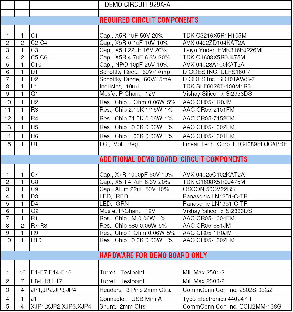
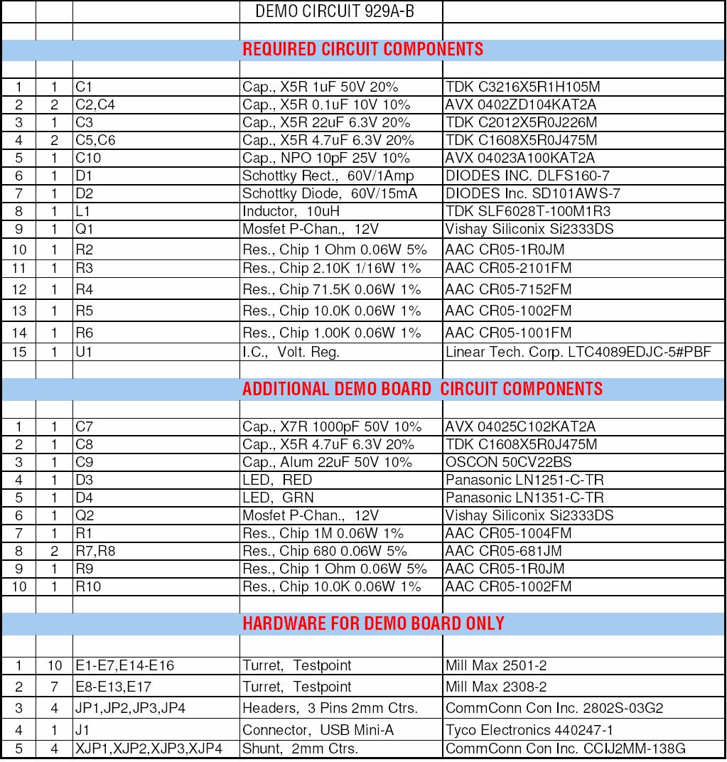
1 LTC4089/-5 DESCRIPTION Demonstration circuit DC929A-A/B is a monolithic high voltage (6V-36V) switching buck regulator, USB Powerpath controller, and Li-Ion battery charger. It is based on the LTC4089/-5 and provides the following functions: 1.2A monolithic buck regulator with output voltage tracking battery voltage V BAT, a 700mA CC/CV timer terminated temperature qualified charger suitable for Li-Ion cells, a USB power manager that insures compliance with the USB power specification and Powerpath management for the battery. The LTC4089/-5 uses the intermediate bus voltage topology that results in faster charging and lower power loss than the charger fed topology. All this functionality consumes less than 2cm 2 of PCB area with all components on one side of the PCB. Design files for this circuit board are available. Call the LTC factory., LTC, LT, and Powerpath are registered trademarks of Linear Technology Corporation. Table 1. Performance Summary PARAMETER CONDITION VALUE HVIN Input Voltage 6V - 36V HVOUT/VOUT V HVIN = 6V - 36V = V BAT +0.3V (for LTC4089) = 5V (for LTC4089-5) Battery Charger I BAT V USB = 5V, Vbat=3.6V 700mA +/- 7% Float Voltage V USB = 5V, battery disconnected from BATT pin 4.20V +/- 35mV Trickle Charge Threshold V USB = 5V 2.9V +/- 0.1V Recharge Threshold V USB = 5V (Vfloat 130mV) to (Vfloat-60mV) USB Current I USB - 500mA Mode V USB = 5V, USB Active 500mA Mode 475mA typical, 500mA max I USB - 100mA Mode V USB = 5V, USB Active 100mA Mode 93mA typical, 100mA max I USB - Suspend Mode V USB =5V, USB Suspend 50uA typical, 100uA max OPERATING PRINCIPLES DC929A-A is the demo board for LTC4089, while DC929A-B is for LTC The only difference is that the voltage on HVOUT/VOUT of LTC4089 tracks battery voltage (0.3V higher than V BAT, with minimum of 3.46V, maximum 4.6V), while that of LTC is fixed at 5V. This chip manages the power supplies that would be typical for a USB powered device and/or a high voltage source, such as fire wire or automotive battery. Power is input from either the USB cable or a high voltage adapter to an intermediate voltage bus VOUT. The intermediate voltage bus is preferentially powered from the adapter, then USB and finally if required from the battery via an internal ideal diode and an optional external MOSFET (Q2). The battery charger is a CC/CV timer terminated type capable of charge currents of up to 1.2A. QUICK START PROCEDURE 1
2 Demonstration circuit DC929A-A/B is easy to set up to evaluate the performance of the LTC4089/-5. Refer to Figure 1 for proper measurement equipment setup and follow the procedure below: 1. Connect input power supply, meters and output load as shown in Figure 1, with the following initial values: PS1 = 0V PS2 = 5V PS3 = 2.5V I USB = 0mA USB Charging 2. Place the USB ON/OFF jumper (JP3) in the ON position. Place the USB Current jumper (JP2) in the 500mA position. Turn on the power supplies, the charger should activate and the charge LED D4 will illuminate. The battery will be in trickle charge mode, I BAT is around 70mA. Increase the battery voltage to above 2.9V the battery charge current (I BAT ) will increase to 470mA. Note that the input current from the USB (I USB ) is about 475mA, which does not exceed the USB spec of 500mA. 3. Now increase the load on the SYSTEM LOAD OUTPUT (I OUT ). Note that as the output load is increased the charging current is decreased and the USB current remains within the 500mA limit. 4. Place the USB current jumper in the 100mA position and note that USB input current falls to maintain compliance with the USB input current spec. Also note that as the external load is increased the battery will start to discharge into the SYSTEM LOAD OUTPUT, illustrating the ideal diode function of the LTC Place the USB ON/OFF jumper (JP1) in the OFF position and note that the USB current falls to under 100uA to comply with the USB suspend mode current. Adapter Charging 6. Ramp up the wall adapter voltage. When the wall adapter exceeds 5.9 volts the LTC4089 will cease drawing current from the USB and switch over to the wall adapter. Both the AC-present LED (D3, red) and charge LED (D4, green) are on. 7. Note that the V OUT of DC929A-A is about 0.3V above V BAT, indicating the adaptive feature of V OUT to minimize the charging power loss. The V OUT of DC929A-B is fixed at 5V. 8. Note that the charge current to the battery has increased to 700mA. 9. Increase the battery voltage to 4.2V and note that the charge current falls to 0. This illustrates the constant voltage portion of the charging characteristic. In the mean time, the charge LED (D4) turns off. Battery Powered Operation 10. Set Both USB input voltage and the adapter input voltage to zero. The battery will now power the load on the System Load Output, illustrating the ideal diode function of the LTC4085. Note that the battery is now being discharged. Other Frequency at charge timer cap C4 changes with charging current, indicating the adaptive feature to ensure the full charge of battery. 11. Pins are provided to all control functions in order to simplify wiring of the demo circuit into a system board. 12. NTC function; provision has been made for connection of an external 10k NTC, for temperature qualified charging. To use this feature set the NTC jumper in the external position and connect the external NTC to the NTC terminal and ground. 2
3 Figure 1. Proper Measurement Equipment Setup 3
4 4
5 5
6 6
QUICK START GUIDE FOR DEMONSTRATION CIRCUIT 1142A-A/B USB POWER MANAGER WITH Li-ION CHARGER AND THREE STEP-DOWN REGULATORS
 DESCRIPTION The DC1142A-A/B contains the LTC3557/LTC3557-1 Power Management Integrated Circuit (PMIC) plus the LT3480EDD high voltage buck controller. The LTC3557/LTC3557-1 is a highly integrated power
QUICK START GUIDE FOR DEMONSTRATION CIRCUIT 658 MULTI-OUTPUT DC/DC CONVERTER POWERED BY 2-CELL, USB OR WALL ADAPTER
 LTC3456 DESCRIPTION Demonstration Circuit 658 is a complete power management system using the LTC3456 for portable applications powered by a wall adapter, a USB port or a 2-cell alkaline battery, in that
QUICK START GUIDE FOR DEMONSTRATION CIRCUIT 1068A DUAL INPUT LI-ION BATTERY CHARGER WITH SYNCHRONOUS BUCK REGULATOR
 Demonstration circuit 1068A is a complete single cell Lithium-Ion battery charger and a synchronous buck voltage regulator with adjustable output voltage. Operating at a frequency of 1.5MHz, the regulator
AP5056. Using SOP8/MSOP8 package 1A Linear Li-Ion Battery Charger. Description. Package. Features. Typical Application Circuit
 Description The AP5056 is a complete constant current & constant voltage linear charger for single cell lithium-ion batteries. Its SOP/MSOP package and low external component count make the AP5056 ideally
Standalone Linear Li-Ion Battery Charger with Thermal Regulation
 Standalone Linear Li-Ion Battery Charger with Thermal Regulation DESCRIPTION The UP4054A is a complete constant-current /constant-voltage linear charger for single cell lithium-ion batteries. It s TSOT23-5
QUICK START GUIDE FOR DEMONSTRATION CIRCUIT DC1059A DUAL IDEAL DIODE POWERPATH TM DEMOBOARD
 DESCRIPTION WARNING: READ THIS MANUAL FIRST BEFORE OPERATING THE DEMOBOARD. THERE ARE ILLEGAL POWER CONFIGURATIONS OR VOLTAGE LEVELS THAT CAN POTENTIALLY DAMAGE THE DEMOBOARD. From the factory: 1) MINIMUM
Switch mode single cell Li+ battery charger with OTG boost, voltage mode fuel gauge and LDO
 User manual Switch mode single cell Li+ battery charger with OTG boost, voltage mode fuel gauge and LDO Introduction This user manual is for the STEVAL-ISB033V1 evaluation board based on the STBCFG01 high
EV2617-L-00A. 3A, 1-Cell Li-Ion Battery Switching Charger With NVDC Power Path Management FEATURES DESCRIPTION APPLICATIONS ELECTRICAL SPECIFICATION
 EV2617-L-00A 3A, 1-Cell Li-Ion Battery Switching Charger With NVDC Power Path Management The Future of Analog IC Technology DESCRIPTION The EV2617-L-00A is an evaluation board for MP2617, a 3A/1.6MHz 1-cell
QUICK START GUIDE FOR DEMONSTRATION CIRCUIT 995A ADJUSTABLE LDO LINEAR REGULATOR LT3080EDD DESCRIPTION
 LT3080EDD DESCRIPTION Demonstration circuit 995A is an adjustable 1.1A linear regulator featuring LT 3080. Architected as a precision current source and voltage follower, it allows this new regulator to
QUICK START GUIDE FOR DEMONSTRATION CIRCUIT 740 TRACKER/SEQUENCER DEMO BOARD
 DESCRIPTION QUICK START GUIDE FOR DEMONSTRATION CIRCUIT 740 LTC2922 Demonstration circuit 740 is a tracker/sequencer demo board featuring the LTC2922 that monitors up to five external power supplies and
G5803 1A Single Cell Li-Ion Battery Linear Charger
 1A Single Cell Li-Ion Battery Linear Charger Features No External Power MOSFET, Sense Resistor or Blocking Diode Required 1% Regulation Voltage Accuracy Programmable Constant Charge Current Limit up to
STBC ma standalone linear Li-Ion battery charger with thermal regulation. Description. Features. Applications
 800 ma standalone linear Li-Ion battery charger with thermal regulation Description Datasheet - production data Features Programmable charge current up to 800 ma No external MOSFET, sense resistors or
Future Technology Devices International Ltd
 Future Technology Devices International Ltd Datasheet UMFT231XC USB to UART with Battery Charger Support UMFT231XC is a USB to UART development module with battery charging support. 1 Introduction 1.1
QUICK START GUIDE FOR DEMONSTRATION CIRCUIT DC512B
 LTC4100 DESCRIPTION Demonstration circuit DC512B is a single battery switching step-down charge controller featuring the LTC4100. The recommended input power is 15 to 20V at 3.5A. A two-position jumper
Operation Manual of Smart Battery Systems (SBS) with SmBus V1.1 support for 12.8V LiFePO4 battery pack (6.6Ah-100Ah)
 with SmBus V1.1 support for 12.8V LiFePO4 battery pack (6.6Ah-100Ah)") Operation Manual of Smart Battery Systems (SBS) with SmBus V1.1 support for 12.8V LiFePO4 battery pack (6.6Ah-100Ah) AA Portable Power Corp (http://www.batteryspace.com) Address: 860 S, 19 th St, Unit
Operation Manual of Smart Battery Systems (SBS) with SmBus V1.1 support for 12.8V LiFePO4 battery pack (6.6Ah-100Ah) AA Portable Power Corp (http://www.batteryspace.com) Address: 860 S, 19 th St, Unit
RT9505. Linear Single Cell Li-Ion Battery Charger IC. General Description. Features. Applications. Ordering Information. Pin Configurations
 Linear Single Cell Li-Ion Battery Charger IC General Description The RT505 is a fully integrated low cost single-cell Li- Ion battery charger IC ideal for portable applications. The RT505 is capable of
AUR9801D. Pin Assignments. Description. Applications. Features LI-ION/LI POLYMER BATTERY CHARGER AUR9801D
 LI-ION/LI POLYMER BATTERY CHARGER Description Pin Assignments The is a highly-integrated battery charger for single-cell Li-ion or Li-polymer batteries capable of operating with an input voltage reached
TSP-BCM48, TSP-BCM48A. Operating Instruction Manual. Page 1 of 13
 Battery Controller Module TSP-BCM24, TSP-BCM24A TSP-BCM48, TSP-BCM48A Operating Instruction Manual http://www.tracopower.com Page 1 of 13 Dimensions drawings: TSP-BCM24 & TSP-BCM48 Weight: 0.816lb Gewicht:
PART TOP VIEW. TO LOAD SINGLE Li+ CELL TO IN LOGIC OUT. Maxim Integrated Products 1
 19-224; Rev 2; 6/3 USB-Powered Li+ Charger General Description The is a single-cell lithium-ion (Li+) battery charger that can be powered directly from a USB port* or from an external supply up to 6.5V.
RT9532. Linear Single Cell Li-Ion Battery Charger IC for Portable Applications. General Description. Features. Applications. Marking Information
 RT9532 Linear Single Cell Li-Ion Battery Charger IC for Portable Applications General Description The RT9532 is a fully integrated single cell Li-ion battery charger IC ideal for portable applications.
Variable Power Supply Digital Control Circuit Diagram Using Lm317
 Variable Power Supply Digital Control Circuit Diagram Using Lm317 DIGITAL POWER SUPPLY USING LM317 A Major Project Report Submitted partial fulfillment of the requirement for the award of the Degree of
QUICK START GUIDE FOR DEMONSTRATION CIRCUIT DC BIT MICROPOWER NO LATENCY DELTA SIGMA ADC LTC2400 DESCRIPTION
 LTC2400 DESCRIPTION This demonstration board features the LTC2400, a 24 bit high performance Σ analog-to-digital converter (ADC). The LTC2400 combines exemplary DC accuracy (INL +/-2ppm, 2.5µV offset,
DS1306. Serial Alarm Real Time Clock (RTC)
") www.dalsemi.com FEATURES Real time clock counts seconds, minutes, hours, date of the month, month, day of the week, and year with leap year compensation valid up to 2100 96-byte nonvolatile RAM for data
www.dalsemi.com FEATURES Real time clock counts seconds, minutes, hours, date of the month, month, day of the week, and year with leap year compensation valid up to 2100 96-byte nonvolatile RAM for data
PS-4100 POWER SUPPLY MANUAL
 PS-4100 POWER SUPPLY MANUAL Manual Part Number 180-0573 December 7, 2006 TABLE OF CONTENTS TITLE PAGE Table of Contents... 2 List Of Figures... 3 1. Introduction... 4 1.0. General... 4 1.1. Features...
OPENUPS 6-34V Intelligent Uninterruptible Power Supply
 OPENUPS 6-34V Intelligent Uninterruptible Power Supply Installation Guide Version 1.0f P/N OPENUPS-06 Before you start Please take a moment and read this manual before you install the OPENUPS. Often times,
XT9502. Linear Li-Ion Battery Charger. General Description. Applications. Features. Package. Ordering Information. Pin Assignment
 Linear Li-Ion Battery Charger General Description series is a double lithium battery charge management chip. The chip includes a charge state detection, the charging process,temperature detection and so
Power LED Driver. By Dushan Grujich, on February 14 th. 2014
 Power LED Driver By Dushan Grujich, on February 14 th. 2014 Most often microscope enthusiasts encounter a problem when converting their microscope illuminator from incandescent lamp to a power LED. Problem
Prioritize Power Sources in Any Order, Regardless of Relative Voltage: No µp Required
 Prioritize Power Sources in Any Order, Regardless of Relative Voltage: No µp Required Sam Tran Does your application have multiple input power sources? Are one or more secondary source voltages equal to
Battery Protection IC for Single-cell Pack
 Battery Protection IC for Single-cell Pack Features Low supply current Normal operation: 3uA typ. @ VCC = 3.9V Power-down mode: 0.1uA max. @VCC = 2.0V Over-charge detection voltage (V CU ) 4.25~4.3V, accuracy:
ACT2823 Evaluation Kit Application Report REV 0, 01-Dec V/3.4A Dual Cell Battery Power Manager
 ACT2823 Evaluation Kit Application Report REV 0, 01-Dec-2016 5V/3.4A Dual Cell Battery Power Manager FEATURES Dedicated single-chip integrated dual cell battery management 4.5V-5.5V input voltage and 3.8A
HM9708 HM9708. Battery-Powered Equipment Motherboard USB Power Switch USB Device Power Switch Hot-Plug Power Supplies Battery-Charger Circuits DC+ VIN
 200mΩ Power Distribution Switches Features 200mΩ Typ. High-Side MOSFET 0.8A Current Limit (V IN =3.0V) Wide Input Voltage Range: 2V ~ 5.5V Soft Start Thermal Protection Small SOT-23-5 Package Minimizes
ASI. Switched-Capacitor Boost Converter 3.3V-5.0V 100mA GENERAL DESCRIPTION FEATURES APPLICATIONS
 ASI Technical Data Sheet Switched-Capacitor Boost Converter 3.3V-5.0V 100mA FEATURES Switched-Capacitor Step-Up Operation Input Range: 2.7V to 5.0V Output Voltage: 3.3V-5.0V (programmable) Output Current:
High-side Power Distribution Switch NCT3521U
 High-side Power Distribution Switch NCT3521U -Table of Content- 1. GENERAL DESCRIPTION...1 2. FEATURES...1 3. APPLICATIONS...2 4. PIN CONFIGURATION AND DESCRIPTION...2 5. TYPICAL APPLICATION CIRCUIT...3
bq24020evm and bq24023evm
 User s Guide bq24020evm and bq24023evm 1-A Single-Chip Li-Ion and Li-Pol Charge Management IC with Autonomous USB-Port and AC-Adapter Supply Management Evaluation Module User s Guide 1 EVM IMPORTANT NOTICE
DEMO MANUAL DC1506A LTC4361 Overvoltage/ Overcurrent Protection Controller DESCRIPTION
 DESCRIPTION Demonstration circuit DC1506A features the LTC 4361 an overvoltage/overcurrent protection controller that safeguards 2.5V to 5.5V systems from input supply overvoltage. The LTC4361 is designed
QUICK START GUIDE FOR DEMONSTRATION CIRCUIT 1243 HOT SWAP CONTROLLER WITH CURRENT AND VOLTAGE MONITOR LTC4215-1
 DESCRIPTION QUICK START GUIDE FOR DEMONSTRATION CIRCUIT 1243 LTC4215-1 Demonstration Circuit 1243A showcases the LTC 4215- -1IUF positive low voltage Hot Swap controller with I2C compatible monitoring
RCB W Rack Mountable Front End Battery Charger. File Name:RCB-1600-SPEC Sicherheit ID
 Bauart gepruft Sicherheit egelma ge od o s be wac g www. tuv.com ID 2000000000 1600W Rack Mountable Front End Battery Charger File Name:-SPEC 2016-06-01 SPECIFICATION MODEL -12-24 BOOST CHARGE VOLTAGE(Vboost)(default)
ACT2804 Demo Board Application Report 5V/3.4A Dual Cell Backup Battery Power Manager
 ACT2804 Demo Board Application Report 5V/3.4A Dual Cell Backup Battery Power Manager FEATURES Dedicated single-chip integrated dual cell battery management 4.5V-5.5V input voltage and 3.4A input current
BC-9000 Field Calibration Procedure CF1_FIELDCAL_BC9000 Revised 03/16/2013
 BC-9000 Field Calibration Procedure CF1_FIELDCAL_BC9000 Revised 03/16/2013 INTRODUCTION: The BC-9000 Battery Charger will recharge12 and 24 volt lead-acid and nickel cadmium batteries. Battery charging
STBC mA Standalone linear Li-Ion Battery charger with thermal regulation. Feature summary. Description. Applications.
 800mA Standalone linear Li-Ion Battery charger with thermal regulation Feature summary Programmable charge current up to 800mA No external MOSFET, sense resistors or blocking diode required Complete linear
EVALUATION KIT AVAILABLE 28V Linear Li+ Battery Charger with Smart Autoboot Assistant OFF
 19-994; Rev 2; 3/8 EVALUATION KIT AVAILABLE 28V Linear Li+ Battery Charger with General Description The intelligent, stand-alone constant-current, constant-voltage (CCCV), thermally regulated linear charger
QUICK START GUIDE FOR DEMONSTRATION CIRCUIT 824 MULTIDISPLAY LED CONTROLLER
 LTC3208 WARNING: The LEDs on this demo board produce very bright light. Do not look directly at LEDs when power is applied. Serious eye damage may occur. DESCRIPTION Demonstration circuit 824 is a multi-display
2 AA Cell to 3.3V USB On-The-Go Devices White LED Drivers Handheld Devices. The HM3200B is available in the 6-pin SOT23-6.
 Low Noise, Regulated Charge Pump DC/DC Converter Features Fixed 3.3V ± 4% Output VIN Range: 1.8V to 5V Output Current: 100mA Constant Frequency Operation at All Loads Low Noise Constant Frequency (1.2MHz)
DEMO MANUAL DC1575B LTC4362-2: Monolithic Overvoltage/ Overcurrent Protector DESCRIPTION
 LTC4362-2: Monolithic Overvoltage/ Overcurrent Protector DESCRIPTION Demonstration circuit 575B features the LTC 4362, a monolithic overvoltage/overcurrent protector that safeguards 2.5V to 5.5V systems
HX4002 HX1001. White LED Backlighting Li-Ion Battery Backup Supplies Local 3V to 5V Conversion Smart Card Readers PCMCIA Local 5V Supplies
 HX1001 Low Noise, Regulated Charge Pump DC/DC Converter Features Fixed 5V±4% Output VIN Range: 2.7V ~ 5V Output Current: up to 250mA (V IN =4.5V) Low Noise Constant Frequency Operation Shutdown Current:
OPENUPS 6-34V Intelligent Uninterruptible Power Supply
 OPENUPS 6-34V Intelligent Uninterruptible Power Supply Installation Guide Version 1.0f Before you start Please take a moment and read this manual before you install the OPENUPS. Often times, rushing into
QUICK START GUIDE FOR DEMONSTRATION CIRCUIT 1420A 12-PORT IEEE 802.3AT PSE INTEGRATED CONNECTOR MODULE (PSE-ICM)
") DESCRIPTION Demonstration circuit 1420A from Linear Technology is a convenient platform for testing and evaluation of a PSE Integrated Connector Module (PSE- ICM) that complies with the PoETec specification.
DESCRIPTION Demonstration circuit 1420A from Linear Technology is a convenient platform for testing and evaluation of a PSE Integrated Connector Module (PSE- ICM) that complies with the PoETec specification.
DLA. DMX512 Analyzer. DLA Users Manual SV2_00 B.lwp copyright ELM Video Technology, Inc.
 DLA DMX512 Analyzer DLA DLA-HH 1 Table Of Contents IMPORTANT SAFEGUARDS... 2 DLA OVERVIEW... 3 CONNECTION... 3 OPERATION... 3 HARDWARE SETUP... 4 DLA-HH (PORTABLE) LAYOUT... 4 CHASSIS LAYOUT... 4 DLA MENU
Energy Management System. Operation and Installation Manual
 Energy Management System Operation and Installation Manual AA Portable Power Corp 825 S 19 TH Street, Richmond, CA 94804 www.batteryspace.com Table of Contents 1 Introduction 3 2. Packing List 5 3. Specifications
MC34708, Silicon Errata
 Freescale Semiconductor Errata Document : Rev. 9.0, 11/2013 MC34708, Silicon Errata Introduction Device Revision Identification This errata document applies to the following devices: Table 1. Silicon Revision
2 in 1 LAN Tester and Multimeter Model:
 2 in 1 LAN Tester and Multimeter Model: 72-8495 1 IMPORTANT SAFETY INFORMATION Please read these instructions carefully before use and retain for future reference. This instrument is designed and manufactured
User Guide. TP3016M Series Switching Mode DC Power Supply
 User Guide TP3016M Series Switching Mode DC Power Supply 1 Introduction I. Quick Start 1.1 Front Panel Description 1.2 Pre-Checking 1.3 Quick Start 1.4 Output Checking II. Specifications 2.1 Major Specification
Adafruit PowerBoost Charger
 Adafruit PowerBoost 500 + Charger Created by lady ada Last updated on 2015-10-21 12:44:24 PM EDT Guide Contents Guide Contents Overview Pinouts Power Pins Control Pins LEDs Battery and USB connection On/Off
THOR Battery Backed DC Power Supply Reference Manual
 THOR Battery Backed DC Power Supply Reference Manual Revision A Firmware Compatibility: V1.03 P/N 60098001 Revised: 4/26/2012 INDUSTRIAL CONTROL LINKS, INC. 12840 Earhart Avenue Auburn, CA 95602 Tel: (800)
Introduction. This unit has a wide input range (6-34V) and it can provide a tightly regulated output ranging from 6 to 24V (default set to 12V).
 and it can provide a tightly regulated output ranging from 6 to 24V (default set to 12V).") Introduction The DCDC-USB is a small yet powerful DC-DC power supply designed to power a wide variety of devices. This DC-DC has a range of intelligent functions not found in any tradition USB converters.
Introduction The DCDC-USB is a small yet powerful DC-DC power supply designed to power a wide variety of devices. This DC-DC has a range of intelligent functions not found in any tradition USB converters.
MP2681 CC/CV Controller with Full Protection and Indication
 MP2681 CC/CV Controller with Full Protection and Indication The Future of Analog IC Technology One Chip Solution for Power Tools Applications DESCRIPTION The MP2681 is a highly integrated Li-Ion or Lipolymer
Pololu 12V Step-Up/Step-Down Voltage Regulator S10V2F12
 Pololu 12V Step-Up/Step-Down Voltage Regulator S10V2F12 Overview The Pololu step-up/step-down voltage regulator S10V2F12 is a switching regulator (also called a switched-mode power supply (SMPS) or DC-to-DC
PARAMETER CONDITIONS MIN TYP MAX UNITS Input Supply Range V I VIN Shutdown Current LEDEN = LOW 3 8 µa I VIN Operating Current.
 DESCRIPTION WARNING! Do not look directly at operating LED. This circuit produces light that can damage eyes. Demonstration circuit 1187 is an RGB LED Driver and Charge Pump featuring the LTC3212. DEMO
SN8200 LI+ DUAL BATTERY CONTROLLER
 LI+ DUAL BATTERY CONTROLLER GENERAL DESCRIPTION The SN8200 is a highly integrated IC to serve as the control logic for a system with multiple power sources. It integrates a mini-charger s path power MOS
MAX8804V/MAX8804W/MAX8804Y/MAX8804Z
 19-785; Rev 2; 4/8 EVALUATION KIT AVAILABLE High-Voltage, Dual-Input, USB/AC General Description The intelligent, dual-input, stand-alone, constant-current, constant-voltage (CCCV), thermally regulated
Adafruit Powerboost 1000C
 Adafruit Powerboost 1000C Created by lady ada Last updated on 2017-03-10 08:56:30 PM UTC Guide Contents Guide Contents Overview Pinouts Power Pins Control Pins LEDs Battery and USB connection Assembly
MP6219 5V, 1A 2A Programmable Current Limit Power Distribution Switch
 The Future of Analog IC Technology MP6219 5V, 1A 2A Programmable Current Limit Power Distribution Switch DESCRIPTION The MP6219 is a protection device designed to protect circuitry on the output from transients
Technical manual for HP8480 Main battery switch with current monitor. + Low power output for rain light. + Battery discharge warning output.
 Technical manual for HP8480 Main battery switch with current monitor. + Low power output for rain light. + Battery discharge warning output. Date: 2018-03-27\KT Page 1 of 10 Table of content 1) Product
RT9526. Linear Single Cell Li-Ion Battery Charger with Input Over Voltage Protection. General Description. Features. Applications. Pin Configurations
 Linear Single Cell Li-Ion Battery Charger with Input Over Voltage Protection General Description The RT9526 is a fully integrated low cost single cell Li-ion battery charger ideal for portable applications.
EXT9502 XX XX X R Tape & Reel Voltage Accuracy: A:±1% B:±2%
 General Description series is a double lithium battery charge management chip. The chip includes a charge state detection, the charging process, temperature detection and so on. The chip also integrates
ACT8945AEV. ACT8945A Evaluation Kit FEATURES GENERAL DESCRIPTION QUICK START GUIDE. Rev 0, 08-Aug-13
 FEATURES Fully Assembled and Tested PCB Allows Simple Evaluation of the ACT8945A Probe Points for Easy Measurement QUICK START GUIDE 1) Variable Power Supply 2) DMM Recommended Equipment 3) Load Resistors
CA-A480-A Elevator Controller. Reference & Installation Manual
 CA-A480-A Elevator Controller Reference & Installation Manual TABLE OF CONTENTS INTRODUCTION.................................................................. 4 Introduction.............................................................................................
12v Power Controller Project Board
 12v Power Controller Project Board 12 Volt Power Controller Introduction This board provides three functions... DC power gate Low voltage disconnect Voltage / current display The typical usage for this
Adafruit PowerBoost Charger
 Adafruit PowerBoost 500 + Charger Created by lady ada Last updated on 2017-06-01 04:08:36 PM UTC Guide Contents Guide Contents Overview Pinouts Power Pins Control Pins LEDs Battery and USB connection On/Off
DEMO MANUAL DC1555C LTC4365/LTC4365-1: Overvoltage, Undervoltage and Reverse Supply Protection Controller Description
 DEMO MANUAL DC555C LTC65/LTC65-: Overvoltage, Undervoltage and Reverse Supply Protection Controller Description Demonstration circuit DC555C is intended to demonstrate the performance of the LTC65 and
Industrial Power Supplies
 50-600 Watt Features Switch mode power supplies for DIN-rail mounting 6 power ranges with 2, 3, 6, 12, 20 and 24 A output current (24 VDC models) Selectable 115/ 230 VAC input Very low ripple and noise
Controller and Programmer to sequential firing detonators in s7 rocket models. Size: 26 x 40 x 12 mm(17mm witch connector)
") Controller and Programmer to sequential firing detonators in s7 rocket models Device was built to sequential firing detonators in s7 rocket models. It is fully programmable device with microprocessor.
Controller and Programmer to sequential firing detonators in s7 rocket models Device was built to sequential firing detonators in s7 rocket models. It is fully programmable device with microprocessor.
Specifications are at T A = 25 C
 Description DC870A is a.5a low dropout linear regulator featuring LT 308. The device is designed for rugged industrial applications and can be paralleled for higher output current or heat spreading. Besides
Relay Configuration Form * Required
 Relay Configuration Form * Required 1. Uni directional or Bi directional Relay? Uni directional relays are installed between a source of voltage/current, and a load. Because the primary semiconductors
Product Data Sheet MA5885 (USB Fast Charging Emulator)
") Table of Contents 1. Description... 2 2. Feature... 2 3. Target Application... 3 4. MA5885 Charging Modes... 3 5. Detail Function Description... 4 6. Pin Assignment... 6 7. Pin Description... 6 8. Electrical
Table of Contents 1. Description... 2 2. Feature... 2 3. Target Application... 3 4. MA5885 Charging Modes... 3 5. Detail Function Description... 4 6. Pin Assignment... 6 7. Pin Description... 6 8. Electrical
PT6104. Multi-Cell Li-ion Battery Pack Charger controller FEATURES GENERAL DESCRIPTION APPLICATIONS TYPICAL APPLICATION DIAGRAM
 GENERAL DESCRIPTION The PT6104 is an high efficiency, pulse frequency modulated (PFM) switching charger controller for 2 or 4 cell li-ion battery packs. It supports three segments of charging periods,
DS2756EVKIT+ High Accuracy Battery Fuel Gauge With Programmable Suspend Mode Evaluation Kit
 19-4847; Rev 9/09 www.maxim-ic.com FEATURES Demonstrates the capabilities of the DS2756 High Accuracy Battery Fuel Gauge, including: Programmable Suspend Mode Temperature measurement Voltage measurement
MAINTENANCE MANUAL. EDACS REDUNDANT POWER SUPPLY SYSTEM 350A1441P1 and P2 POWER MODULE CHASSIS 350A1441P3, P4, AND P5 POWER MODULES TABLE OF CONTENTS
 MAINTENANCE MANUAL EDACS REDUNDANT POWER SUPPLY SYSTEM 350A1441P1 and P2 POWER MODULE CHASSIS 350A1441P3, P4, AND P5 POWER MODULES TABLE OF CONTENTS SPECIFICATIONS*... 2 INTRODUCTION... 3 DESCRIPTION...
DEMO MANUAL DC2255A LTC3106EUDC 300mA, Low Voltage Buck-Boost Converter with PowerPath and 1.6µA Quiescent Current
 DESCRIPTION DEMO MANUAL DC55A LTC306EUDC 300mA, Low Voltage Buck-Boost Converter with PowerPath and.6µa Quiescent Current Demonstration circuit DC55A features the LTC 306, an ultralow input voltage buck-boost
Automation Interface Requirements for System I/O Interface of a DPC I Welding System
 - 1 - Automation Interface Requirements for System I/O Interface of a DPC I Welding System The DPC I welding system offer several features that are intended to communicate with automation. These features
If It s Electronic, It Needs a Clock
 REAL-TIME CLOCKS MIXED-SIGNAL DESIGN GUIDE Data Sheets Application Notes Free Samples If It s Electronic, It Needs a Clock 8th EDITION No matter what you design, you need your system to accurately keep
EPS USER MANUAL. Electrical Power System (EPS)
") EPS USER MANUAL Electrical Power System (EPS) 1 Change Log... 3 2 Acronyms List... 4 3 Highlighted Features... 5 4 System Description... 5 5 Block Diagram... 11 6 Connector Pinout... 11 Connectors Location...
EPS USER MANUAL Electrical Power System (EPS) 1 Change Log... 3 2 Acronyms List... 4 3 Highlighted Features... 5 4 System Description... 5 5 Block Diagram... 11 6 Connector Pinout... 11 Connectors Location...
Model HM-535 Power Supply Installation and Service Instructions
 Model HM-535 Power Supply Installation and Service Instructions 430-535 0104 2004 Heritage MedCall, Inc SENTRY INSTALLATION & SERVICE INSTRUCTIONS POWER SUPPLY UNIT Model HM-535 IMPORTANT SAFETY INSTRUCTIONS
Considerations for Use. of the SITOP DC UPS Module
 Considerations for Use of the SITOP DC UPS Module 6A without interface 6A with serial interface 6A with USB interface 15A without interface 15A with serial interface 15A with USB interface 40A without
SAT BMS. User Guide. Rev
 SAT BMS User Guide Rev001. 2015.11 CONTENTS 1 SAFETY... 3 1.1 General guidance... 3 2 SAT BMS Introduction... 4 2.1 General overview... 4 2.2 BMS General wiring structure... 4 2.3 Hardware... 4 2.4 Program...
HERCULES-5000 INSTRUCTION MANUAL
 IndustrieAlpine Allee 1 D - 94513 Schönberg Tel.:+49 (0) 85 54/9609-0 Fax:+49 (0) 85 54/96 09 20 Mail: sales@tetelectronics.de INSTRUCTION MANUAL HERCULES-5000 High-performance power supplies Page 1 von
INTRODUCTION CT87E FEATURES AND CONTROLS
 INTRODUCTION The CT87E is a precision instrument used to monitor and record the presence or absence of voltage, light, or sound level such as what would be produced by an operating electric motor or compressor.
Single-/Dual-Input 1-Cell Li+ Chargers with OVP Protection and Programmable Charge Timer
 19-3565; Rev 3; 12/8 EVALUATION KIT AVAILABLE Single-/Dual-Input 1-Cell Li+ Chargers with General Description The single-/dual-input linear battery chargers safely charge single-cell Li+ batteries. The
ADC7520 SERIES. 1600W Battery Chargers and Power Supplies
 ADC7520 SERIES 1600W Battery Chargers and Power Supplies Wide output adjustment range 0 72VDC Analog control by external 0-5VDC voltage Temp.comp charging, sense as on option Power fail relay alarm Master-Slave
Installation Manual for D244X Series 24-volt Power Supplies
 Installation Manual for D244X Series 24-volt Power Supplies D2441-B D2441-C D2443-B D2443-C D2445-B D2445-C D2400 Series 1A 24 volts 1A 24 volts 3A 24 volts 3A 24 volts 5A 24 volts 5A 24 volts Dycon Power
LEGO Energy Meter. How to Get Started
 LEGO Energy Meter How to Get Started The Energy Meter consists of two parts: the LEGO Energy Display and LEGO Energy Storage. The Energy Storage fits onto the bottom of the Energy Display. To install the
Adafruit Powerboost 1000 Basic
 Adafruit Powerboost 1000 Basic Created by lady ada Last updated on 2018-08-22 03:42:57 PM UTC Guide Contents Guide Contents Overview Pinouts Power Pins Control Pins (https://adafru.it/dlz)leds Battery
bq2056 Designed to Go Parts List General Description bq2056 Charge Algorithm Current Voltage
 Designed to GO... Practical and Cost-Effective Battery Management Design Examples by Benchmarq Series 2056, Number One Single- and Double-Cell Low-Dropout Lithium-Ion Charger Using the bq2056 Features
1.5A Dual-Input USB/AC Adapter Charger and Smart Power Selector
 19-781; Rev ; 4/7 1.5A Dual-Input USB/AC Adapter Charger General Description The is an integrated 1-cell Li+ charger and Smart Power Selector with dual (DC and USB) power inputs. It can operate with either
SEI-USB. SEI to USB Adapter Page 1 of 5. Description. Features
 Description SEIUSB Page 1 of 5 The SEIUSB is an interface module that connects US Digital's SEI compatible devices to a standard USB 1.1 / 2.0 port. The SEI (Serial Encoder Interface) bus is a network
A brief user guide Universal Learning Remote Controller
 A brief user guide Universal Learning Remote Controller Program from a PC: 1. Construct a programming cable with a DB-9 female connector. Locate pad J1 from the Universal Learning Remote Controller (ULRC)
DEMO MANUAL DC1520A LT3690: 36V/4A µpower Synchronous Buck Regulator DESCRIPTION PERFORMANCE SUMMARY
 DESCRIPTION Demonstration circuit 1520A is a 36V, 4A synchronous Buck Regulator with 70μA Quiescent Current featuring the LT3690. The demo board is designed for 3.3V output from a 4.5V to 36V input with
Product Specifications
 Product Specifications Models: USC-10001, USC-10002 USC-20001, USC-20002 USC-30001, USC-30002 Guide Specification for UniStar C Series Rack/Universal 1, 2, 3Kva Single-Phase, On-Line Double Conversoin
Integrated Battery Control System LBCS Step-by-Step Setup Guide
 Integrated Battery Control System LBCS Step-by-Step Setup Guide 1. Components of the System 2. Components of the System 3. LBCS Overview 4. Battery Connections 5. Sense Board Installation 6. Sense Board
QUICK START GUIDE FOR DEMONSTRATION CIRCUIT 1110 SINGLE, PARALLEL, IOUT, 16-BIT DAC
 DESCRIPTION QUICK START GUIDE FOR DEMONSTRATION CIRCUIT 1110 LTC2751-16 Demonstration circuit 1110 features the LTC2751 16- Bit SoftSpan Iout DAC. This device has six output ranges, 0 to 5V, and 0 to 10V,