Regenerative Power Module And Common Bus RPM Panels Instruction Manual
|
|
|
- Harvey Parks
- 6 years ago
- Views:
Transcription

1 Regenerative Power Module And Common Bus RPM Panels Instruction Manual Part Number September 2010 Copyright 2010 Magnetek Material Handling
2
3 PRODUCT MANUAL SAFETY INFORMATION Magnetek, Inc. (Magnetek) offers a broad range of radio remote control products, control products and adjustable frequency drives, and industrial braking systems for material handling applications. This manual has been prepared by Magnetek to provide information and recommendations for the installation, use, operation and service of Magnetek s material handling products and systems (Magnetek Products). Anyone who uses, operates, maintains, services, installs or owns Magnetek Products should know, understand and follow the instructions and safety recommendations in this manual for Magnetek Products. The recommendations in this manual do not take precedence over any of the following requirements relating to cranes, hoists lifting devices or other material handling equipment which use or include Magnetek Products: Instructions, manuals, and safety warnings of the manufacturers of the equipment where the radio system is used, Plant safety rules and procedures of the employers and the owners of facilities where the Magnetek Products are being used, Regulations issued by the Occupational Health and Safety Administration (OSHA), Applicable local, state or federal codes, ordinances, standards and requirements, or Safety standards and practices for the industries in which Magnetek Products are used. This manual does not include or address the specific instructions and safety warnings of these manufacturers or any of the other requirements listed above. It is the responsibility of the owners, users and operators of the Magnetek Products to know, understand and follow all of these requirements. It is the responsibility of the employer to make its employees aware of all of the above listed requirements and to make certain that all operators are properly trained. No one should use Magnetek Products prior to becoming familiar with and being trained in these requirements and the instructions and safety recommendations in this manual. WARRANTY INFORMATION FOR INFORMATION ON MAGNETEK S PRODUCT WARRANTIES BY PRODUCT TYPE, PLEASE VISIT Page 3 of 20
4 Disclaimer of Warranty Magnetek, hereafter referred to as Company, assumes no responsibility for improper programming of a drive by untrained personnel. A drive should only be programmed by a trained technician who has read and understands the contents of this manual. Improper programming of a drive can lead to unexpected, undesirable, or unsafe operation or performance of the drive. This may result in damage to equipment or personal injury. Company shall not be liable for economic loss, property damage, or other consequential damages or physical injury sustained by the purchaser or by any third party as a result of such programming. Company neither assumes nor authorizes any other person to assume for Company any other liability in connection with the sale or use of this product. WARNING Improper settings of this product can lead to unexpected, undesirable, or unsafe operation or performance of the controls. Page 4 of 20
5 General Description The Regenerative Power Module (RPM) is a universal brake chopper circuit designed to dissipate regenerative energy produced by a motor into a fixed resistor load. The universal module covers the DC supply voltage range from 200V to 660V. The voltage selector link located on the outside front cover of the unit configures the module for LOW voltage (200V to 300V), MED voltage (300V to 500V) or HIGH voltage (500V to 660V). The module is powered from the DC bus and requires no additional power supplies. The module can either be connected behind the M contactor of each drive or can be connected to the incoming DC bus using a separate mounted controller that includes additional protective components and line capacitance. This module is required whenever the main power supply cannot receive the regenerated power being return to the line. The voltage on the OmniPulse DDC bus rises rapidly during regeneration (100 ms). Bus feed rectifier units that do not have a dump circuit or have slow reacting circuits require the use of the RPM module and dump resistor. RPM Features Ratings Input Voltage Range Brake Level Adjustment Range Rated Amps Peak Brake Current Duty Cycle (800A peak) Minimum connected dump resistor Maximum Operating Temperature Minimum Operating Temperature Minimum 200VDC Maximum 660 VDC Minimum 256 VDC Maximum 800 VDC 400A 800A 10% (40 C ambient) 5% (60 C ambient) 1 ohm 60 C -20 C Universal Module (Voltage selector link, located on the front of the unit, configures module to DC Bus voltage) Link Setting DC Bus Range 330 V (Low) VDC 495 V (Medium) VDC 660 V (High) VDC Page 5 of 20
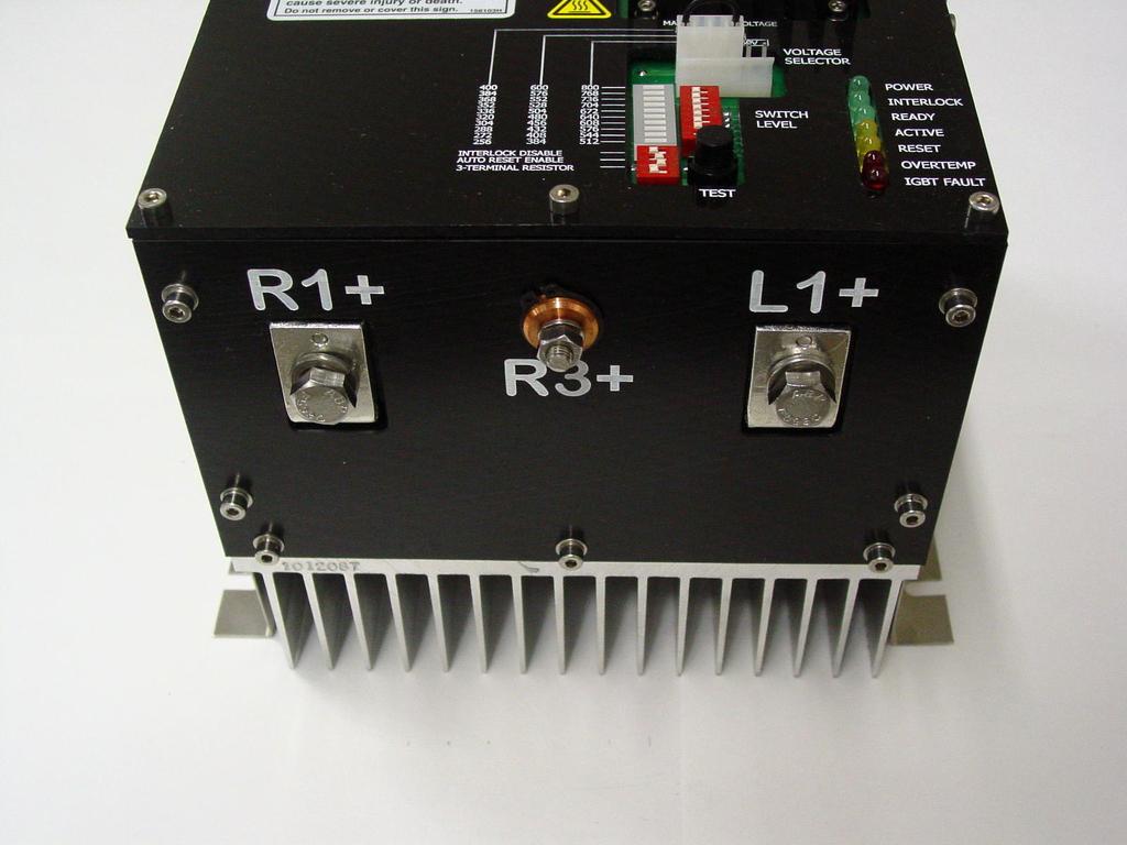
6 Voltage Display A 10-LED Switch Level bar graph provides a visual display of the approximate bus voltage level when the brake transistor turns on. Simplified Switching Level Selection An 8-position DIP switch provides transistor turn on switching level selection in 15 steps. Link Setting Adj Range Volt/Step VDC Choose the appropriate setting for the voltage link set up and set the appropriate corresponding DIP switch position on. All other DIP settings must be off. Mode Switches A 4-position DIP switch provides the following configuration selections: DIP Position Off Setting On Setting 1 Enable Ext Intlk Disable Ext Intlk 2 Auto Reset Remote Reset 3 2-Term Res 3-Term Res 4 Not Used Not Used The External Interlock may be used for the connection of a normally closed temperature switch mounted at the power resistor. Overheat Protection The thermistor mounted on the heat sink is used to protect against failure caused by excessive duty combined with excessive ambient temperatures. The unit is shut down when the heat sink temperature exceeds 95 C. 24V Output for Fan A +24V Fan output is available for supplemental cooling. The Fan output is capable of delivering up to 5W for the addition of an external fan separately mounted from the RPM unit. The output becomes active when the heat sink temperature exceeds 65 C. Page 6 of 20
7 LED Fault and Status Indicators LED status indicators provide the following indications: COLOR MARKING DESCRIPTION GREEN POWER Indicates that the brake chopper power supply is present GREEN INTERLOCK Indicates that the external contact is closed when the interlock is enabled or that the interlock is in the disabled position GREEN READY Indicates that no fault condition exists and that the external interlock is not open AMBER ACTIVE Indicates that the brake chopper is conducting AMBER RESET Indicates that the reset circuit is activated RED OVERTEMP Indicates that the heat sink temperature has reached 95 C and the module has shut down to protect the transistor. RED IGBT FAULT Indicates that the module is shut down on short circuit IGBT detection TEST Switch The TEST switch simulates a DC bus voltage increase; this input is used to set the turn on voltage and verify transistor and resistor functionality. Page 7 of 20
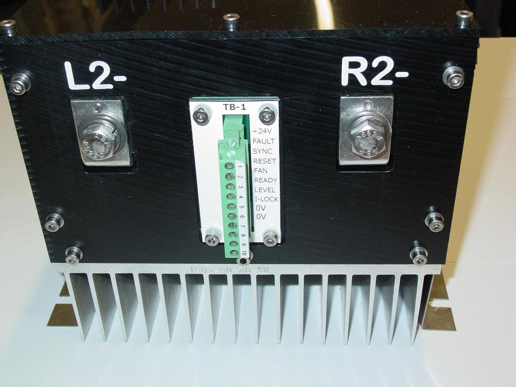
8 External Control Terminals A pluggable Phoenix screw terminal connector is provided to facilitate additional functionality: Pin Signal Name Function 1 External +24V Supply Allows control circuit of the brake module to be powered from an external supply. (Eliminates 25ms delay for control power to become established from main DC bus power.) 2 Fault 24 volts between this terminal and terminal 9 or 10 indicates that the brake module is in a fault condition. This can be used for remote fault annunciation. 3 Sync Connect to same terminal of other brake modules to synchronize switching in order to balance brake load between two or more modules. The 0V pins of synchronized modules must also be connected together. 4 Reset Apply positive pulse between 10V and 24V to remotely reset a brake module fault. 5 Fan The 24-volt DC Fan output is capable of delivering up to 5W of power for the addition of an external fan separately mounted from the RPM unit. The output becomes active when the heat sink temperature exceeds 65 C. Connect between terminals 5 and Ready 24 Volt output, RPM ready 7 Level Brake level switching allows the switching voltage turn on level to be reduced by as much as 100 volts. The voltage input to terminal 7 can be fixed or variable and needs to be connected to the 0V circuit common. See FIGURE 1 for a graphic representation of the dynamic adjustment capability. 8 I-Lock Connection point for resistor overheat protection switch. Normally-closed switch: Connect between either terminals 8 and 9 or 8 and 10. Input has a 50 ms filter to reduce noise. 9 0V Control circuit common. 10 0V Control circuit common Page 8 of 20
9 Switching level Normal switching level 100V 0V Terminal 7 Voltage 10V FIGURE 1 Turn On Dynamic Adjustment RPM UNIT FIGURE 2 Syncrhonization Connection Page 9 of 20
10 Power Terminal Connections TERM Function L1+ DC Bus Positive L2- DC Bus Negative R1+ Resistor Positive (Same potential as DC Bus Positive) R2- Resistor Negative (Switched Output) R3+ Terminal must be connected to the external resistor whenever the separate mounted RPM panel with the required additional protective components is connected directly to the DC bus. See FIGURE 4 for example connections. External Power Connection An external 24V supply may be connected to the brake chopper at pins 1 and 10. The internal 24 and 15 volt power supplies of the brake chopper is derived from the main DC bus input and takes approximately 50ms to start up. If it is necessary for the brake chopper to be active within less than 50ms of applying the DC bus voltage an external power supply should be provided. The external 24-volt DC supply is not needed on crane applications using the OmniPulse DDC. Synchronization Synchronization equalizes the power dissipation in the braking resistors. When two or more brake chopper modules are connected to the same DC bus they should be synchronized by linking together all of the SYNC signals on all modules and linking together a 0V common from each module. See FIGURE 2 for connection. When the DC bus voltage exceeds the voltage threshold of any of the brake choppers the SYNC signal will turn all of them on. The DC bus voltage must fall below the voltage threshold of all choppers in order for the synchronized modules to turn off. Page 10 of 20
11 Resistor Sizing The minimum connected resistor to the standard RPM module is 1 ohm. The resistor value can be greater than this but never lower. Use the following procedure to calculate the continuous current rating of the resistor chosen. 1. Tabulate all motion Full Load Amps (FLA) ½ hour FLA for hoist motion 1 hour FLA for travel motions 2. Calculate Regen Current for simultaneous motion operation I REGEN = FLA *0.8 + FLA *0. 3 HOIST TRAVEL 3. Size RPM Unit(s) and external resistors as close as possible to calculated value. Page 11 of 20
12 L1(+) R1 RPM resistor L1 (+) for RPM is connected between M contactor and the DDC drive L1(+) RPM R2 R3 * L2(-) L2(-) + 24 VDC FAULT SYNCH RESET FAN READY BRAKE LEVEL INTERLOCK 0 VDC 0VDC * EXTERNAL RESISTOR GRIDS WITH NORMALLY- CLOSED OVER TEMPERATURE SWITCH IN THIS CONFIGURATION SET DIP SWITCH - 3 TERMINAL RESISTOR TO OFF POSITION ON RPM UNIT FIGURE AMP Single RPM Unit The connection shown in FIGURE 3 is a single 400 AMP RPM Unit that is connected to the DDC bus after the M contactor. This is the simplest connection possible and requires no additional protective components. Page 12 of 20
13 FIGURE AMP V Common Bus RPM Panel The connection in FIGURE 4 shows a separately mounted 400 AMP RPM Panel that is connected across the V. The panel is generally connected on the load side of the Manual Magnetic Disconnect Switch. Connections direct to the DC Bus require additional protective components that are included on the separately mounted RPM panel. WARNING Warning: Connecting the RPM Module directly to the DC Bus without the additional components shown above can result in damage to the RPM unit and other equipment on the common bus. Page 13 of 20
14 FIGURE AMP V Separate Mounted The connection in FIGURE 5 shows a separately mounted 400 AMP RPM Panel that is connected across the V. The panel is generally connected on the load side of the Manual Magnetic Disconnect Switch. Connections direct to the DC Bus require additional protective components that are included on the separately mounted RPM panel. Page 14 of 20
15 FIGURE AMP V Separate Mounted RPM Panel The connection in FIGURE 6 shows an 800 AMP RPM Panel that is connected across the V. The panel is generally connected on the load side of the Manual Magnetic Disconnect Switch. The Synchronization line is connected between both RPMs in order to have proper load sharing. Page 15 of 20
16 FIGURE AMP V Separate Mounted RPM Panel The connection in FIGURE 7 shows an 800 AMP RPM Panel that is connected across the V. The panel is generally connected on the load side of the Manual Magnetic Disconnect Switch. The Synchronization line is connected between both RPMs in order to have proper load sharing. Page 16 of 20
17 FIGURE AMP V Common Bus RPM Panel The connection in FIGURE 8 shows a 1200 AMP RPM Panel that is connected across the V. The panel is generally connected on the load side of the Manual Magnetic Disconnect Switch. The Synchronization line is connected between both RPMs in order to have proper load sharing. Page 17 of 20
18 FIGURE AMP V Common Bus RPM Panel The connection in FIGURE 9 shows a 1200 AMP RPM Panel that is connected across the V. The panel is generally connected on the load side of the Manual Magnetic Disconnect Switch. The Synchronization line is connected between both RPMs in order to have proper load sharing. Page 18 of 20
19 Troubleshooting Taking the following measurements can check the transistor and diode. Q1 POSITIVE PROBE NEGATIVE PROBE READING DP R2 L DN L2 R QP L1 R2 > 0.6 QN R2 L2 > 0.6 TRANSISTOR AND DIODE CHECK USING D.M.M. SET ON DIODE SCALE FIGURE 10 If the Green POWER indicator light on the front cover is out make the following checks. 1. Check for the supply voltage between L1+ and L2-2. If the supply voltage is present replace the entire RPM unit. Page 19 of 20
20 FIGURE 11 Dimensions 400 AMP RPM Unit Enclosure Dimensions The following table describes the dimensions for the common bus RPM panels. The NEMA 4 enclosures have screw latches to secure the hinged door. Part Number Description Dimensions (in) Height Width Length Amp/230~320 VDC RPM Panel Amp/ VDC RPM Panel Amp/230~320 VDC RPM Panel Amp/360~720 VDC RPM Panel Amp/360~720 VDC RPM Panel Amp/360~720 VDC RPM Panel FIGURE 12 Enclosure Dimensions for the Common Bus RPM Panels Page 20 of 20
MODERNIZE YOUR DC CRANES. Convert Your DC Controls to State-of-the-Art Energy Efficient OmniPulse DDC Series 2 Drives
 TM MODERNIZE YOUR DC CRANES Convert Your DC Controls to State-of-the-Art Energy Efficient OmniPulse DDC Series 2 Drives Magnetek, the leader in digital power and motion control systems, brings you the
Magnetek Dynamic Braking Resistors
 Magnetek Dynamic Braking Resistors Motor Control Instruction Manual N49 W13650 Campbell Drive Menomonee Falls, WI 53051 Phone: 1-800-288-8178 Fax: 1-800-298-3503 SERVICE: 1-866-MAG-SERV (1-866-624-7378)
D115 The Fast Optimal Servo Amplifier For Brush, Brushless, Voice Coil Servo Motors
 D115 The Fast Optimal Servo Amplifier For Brush, Brushless, Voice Coil Servo Motors Ron Boe 5/15/2014 This user guide details the servo drives capabilities and physical interfaces. Users will be able to
Vector Drive - Troubleshooting Guide
 Haas Technical Documentation Vector Drive - Troubleshooting Guide Scan code to get the latest version of this document Translation Available The Haas Vector drive is the source of power for the spindle
VLT 2800 DRIVE SPECIFICATIONS
 VLT 2800 DRIVE SPECIFICATIONS Drive Input Power Input voltage 3 phase... 200 through 240, or 380 through 460; 3-phase all ratings 200 through 240, 1-phase through 2 HP Input voltage range for full output...
Magnetek Material Handling IMPULSE LINK 4.1 Basic Instruction Manual
 Magnetek Material Handling IMPULSE LINK 4.1 Basic Instruction Manual March 2013 Part Number: 140-10350 R6 Copyright 2013 Magnetek Material Handling 2013 MAGNETEK MATERIAL HANDLING All rights reserved.
R325P Single Axis Driver
 R325P Single Axis Driver User Manual And Commands Guide Version 1.3 Thank you for purchasing the R325P Single-Axis Step & Direction Driver. This product is warranted to be free of manufacturing defects
PHASETRONICS. SCR Power Control Specialists. EP1 Series Power Control Single Phase SCR Amps OPERATION & SERVICE MANUAL
 PHASETRONICS Specialists EP1 Series Power Control Single Phase SCR 10-50 Amps OPERATION & SERVICE MANUAL Phasetronics, Inc. P.O. Box 5988 1600 Sunshine Drive Clearwater, FL 33765 (727)573-1900 FAX(727)573-1803
Resolver to Digital Expansion Board
 Resolver to Digital Expansion Board Catalog No. EXB009A01 Installation and Operating Manual 6/98 MN1313 Table of Contents Section 1 General Information............................. 1-1 Introduction....................................
Installation, Testing, and Operating Procedures 30 AMP PORTABLE AND PERMANENT SERIES GFCI SINGLE and MULTIPHASE
 IMPORTANT! Please read all the information on this sheet. SAVE THESE INSTRUCTIONS! NOTICE BEFORE USING READ INSTRUCTIONS COMPLETELY. TO BE INSTALLED BY A QUALIFIED ELECTRICIAN IN ACCORDANCE WITH NATIONAL
NEW! THE NEXT GENERATION OF CRANE PERFORMANCE. Adjustable Frequency Crane Controls
 NEW! THE NEXT GENERATION OF CRANE PERFORMANCE & Adjustable Frequency Crane Controls IMPULSE G+ AND VG+ SERIES 4 ADJUSTABLE FREQUENCY CRANE CONTROLS The Next Generation of Crane Performance Magnetek s new
Magnetek Material Handling IMPULSE LINK 4.1 WDS
 Magnetek Material Handling IMPULSE LINK 4.1 WDS WDS Configurator Instruction Manual Part Number: 144-17658 R2 Copyright 2013 Magnetek Material Handling PRODUCT MANUAL SAFETY INFORMATION Magnetek, Inc.
Expansion Unit Catalog Nos , - 152, - 153, - 154, - 156, -E157
 PRODUCT DA TA SLC 150 110 Expansion Unit Catalog Nos. 1745-151, - 152, - 153, - 154, - 156, -E157 7 : The EXpdnSiQn Unit The SLC 150 expansion unit can be used with either the SLC 150 processor unit or
DCS-E 1kW Series, DLM-E 3kW & 4kW Power Supplies
 DCS-E 1kW Series, DLM-E 3kW & 4kW Power Supplies M51A Option: Isolated Analog Programming Manual Power Supplies Elgar Electronics Corporation 9250 Brown Deer Road San Diego, CA 92121-2294 1-800-73ELGAR
DG4S series DC Servo drive
 DG4S series DC Servo drive User s Manual and Installation Guide Contents 1. Safety, policy and warranty. 1.1. Safety notes. 1.2. Policy. 1.3. Warranty. 2. Electric specifications. 2.1.Operation ranges.
SECTION VARIABLE FREQUENCY DRIVES
 PART 1 GENERAL 1.01 DESCRIPTION This specification section establishes the requirements for variable frequency motor drives. The associated motor(s) shall be specified separate from the drive and listed
EV Controls user Guide
 EV Controls user Guide Copyright EV Controls Table of Contents Introduction... EV Controls System Features... General guidelines for installation... Inverter Electrical Pinout Sheet... Drive Inverter Connections...
Vector Drive - Troubleshooting Guide
 Haas Technical Documentation Vector Drive - Troubleshooting Guide Scan code to get the latest version of this document Translation Available The Haas Vector drive is the source of power for the spindle
Vector Drive - Troubleshooting Guide
 Haas Technical Documentation Vector Drive - Troubleshooting Guide Scan code to get the latest version of this document Translation Available The Haas Vector drive is the source of power for the spindle
Installation, Operation and Maintenance Manual
 Document 481200 VGD-100 Vari-Green Drive Installation, Operation and Maintenance Manual Please read and save these instructions for future reference. Read carefully before attempting to assemble, install,
ZC Series Zone Monitoring Controllers
 ZC Series Zone Monitoring Controllers Installation Instructions MANUAL Reset Controllers Model Description Part Number ZC-1 1 Zone Controller 0421 ZC-2 2 Zone Controller 0422 ZC-3 3 Zone Controller 0423
Hybrid AC Driver [GCNC-1110]
![Hybrid AC Driver [GCNC-1110]](/thumbs/86/94474371.jpg "Hybrid AC Driver [GCNC-1110]") Page 1 Installation Manual and Datasheet Page 2 Key Features Smooth and quiet operation at all speeds and extremely low motor heating Industrial grade performance for an alternating current servo motor
Page 1 Installation Manual and Datasheet Page 2 Key Features Smooth and quiet operation at all speeds and extremely low motor heating Industrial grade performance for an alternating current servo motor
Analog Input Installation Manual
 Analog Input Installation Manual August 2011 Part Number: 144-23917 Copyright 2011 Magnetek 1. Preface and Safety Magnetek manufactures products used as components in a wide variety of industrial systems
Brushless DC Motor Controller Specification Assembly 025A0053
 Brushless DC Motor Controller Specification Assembly 025A0053 600A0053 Rev. 2 July 28, 2004 025A0053 Brushless DC Motor Controller Data Sheet Page 1 Revision History Date Rev Description By 5/15/04 1 Initial
Installation Instructions
 Installation Instructions (Catalog Number 1771-OD) This document provides information on: Because of the variety of uses for the products described in this publication, those responsible for the application
S66 Series Electronic Fan Speed Control
 FANs 121, 125, 1628.3 Product/Technical Bulletin S66 Issue Date 0918 S66 Series Electronic Fan Speed Control The S66 Series Electronic Fan Speed Control is designed to modulate the speed of single-phase,
DC to DC Motor Control Instruction Manual
 DC to DC Motor Control Instruction Manual Software Number: 44300 Part Number: 144-47014 R0 Copyright 2018 Magnetek Page i Page Intentionally Left Blank Table of Contents Chapter 1 Introduction...1-1 1
Standard Options. Model 4100 Position Indicating Meter. Three Phase Motor Control. Positran Transmitter
 Standard Options Model 4100 Position Indicating Meter A percent-of-full-travel meter is supplied with a trim potentiometer resistor, terminal block and connectors. A potentiometer is required in the actuator
24/48/120 VAC Interface Card Instruction Manual
 24/48/120 VAC Interface Card Instruction Manual Distributed by Ergonomic Partners Sales@ErgonomicPartners.com www.ergonomicpartners.com Tel: (314) 884-8884 April 2012 Part Number: -R2 Copyright 2012 Magnetek
ATS22C17Q. Main. Range of product Altistart 22. Component name. Factory setting current. Utilisation category. IP degree of protection
 Product datasheet Characteristics ATS22C17Q Complementary Assembly style Function available Supply voltage limits Main Range of product Altistart 22 Product or component type Product destination Product
GV3000/SE AC Drive ControlNet Network Communication Option Board M/N 2CN3000
 GV3000/SE AC Drive ControlNet Network Communication Option Board M/N 2CN3000 Instruction Manual D2-3390-2 The information in this manual is subject to change without notice. Throughout this manual, the
Rhino Buffer Module PSM24-BFM600S. Operating Instructions
 Rhino Buffer Module PSM24-BFM600S Operating Instructions RHINO BUFFER MODULE PSM24-BFM600S Description The PSM24-BFM600S Buffer Module will hold the output voltage of a 24 VDC power supply after brownouts
ATS22D17Q soft starter-ats22-control 220V-power 230V (4kW)/ V(7.5kW)
/ V(7.5kW)") Product datasheet Characteristics ATS22D17Q soft starter-ats22-control 220V-power 230V (4kW)/400...440V(7.5kW) Complementary Assembly style Function available Supply voltage limits Main Range of product
Product datasheet Characteristics ATS22D17Q soft starter-ats22-control 220V-power 230V (4kW)/400...440V(7.5kW) Complementary Assembly style Function available Supply voltage limits Main Range of product
SmartVFD Disconnect Panel Assemblies
 SmartVFD Panel Assemblies INSTALLATION INSTRUCTIONS APPLICATION Only The SmartVFD Panel Assemblies channel electrical power either through or around the variable frequency drive (VFD). INSTALLATION When
Profibus DP Expansion Board
 Profibus DP Expansion Board Catalog No. EXB014A01 Installation and Operating Manual 8/03 MN1323 Table of Contents Section 1 General Information................................... 1-1 Introduction.........................................
MAINTENANCE MANUAL. EDACS REDUNDANT POWER SUPPLY SYSTEM 350A1441P1 and P2 POWER MODULE CHASSIS 350A1441P3, P4, AND P5 POWER MODULES TABLE OF CONTENTS
 MAINTENANCE MANUAL EDACS REDUNDANT POWER SUPPLY SYSTEM 350A1441P1 and P2 POWER MODULE CHASSIS 350A1441P3, P4, AND P5 POWER MODULES TABLE OF CONTENTS SPECIFICATIONS*... 2 INTRODUCTION... 3 DESCRIPTION...
Sierra 80 Volt Brushless DC Motor Controller Product Specification
 Sierra 80 Volt Brushless DC Motor Controller Product Specification Assembly 025F0135 600A0588 Rev. B January 29, 2010 025F0135 Brushless DC Motor Controller Page 1 Revision History ECN # Date Rev Description
User s Manual. Extremely Low Noise 3-phase Microstepping Driver. For 3L583M. Version All Rights Reserved
 User s Manual For Extremely Low Noise 3-phase Microstepping Driver Version 1.0 2008 All Rights Reserved Attention: Please read this manual carefully before using the driver! The content in this manual
SECTION SOLID-STATE REDUCED VOLTAGE STARTERS
 SECTION 26 29 13.16 PART 1 - GENERAL 1.1 THE REQUIREMENT A. General: The CONTRACTOR shall provide solid-state reduced voltage motor starters, complete and operable, in accordance with the Contract Documents.
User Manual of 3M583
 ECG-SAVEBASE EMAIL:EBAY@SAVEBASE.COM WEB: HTTP://STORES.EBAY.CO.UK/SAVEBASE User Manual of 3M583 High Performance Microstepping Driver ECG-SAVEBASE ECG Safety Statement Easy Commercial Global is not liable
INTER PLANT STANDARD STEEL INDUSTRY
 INTER PLANT STANDARD STEEL INDUSTRY PARTICULAR REQUIREMENTS OF ROLLING MILL VVVF DRIVES IPSS: 1-10-043-15 IPSS CORRESPONDING IS DOES NOT EXIST 0. FOREWORD 0.1 This Inter Plant Standard has been prepared
RE-82 RACK MOUNT DIMMER OWNERS MANUAL. 8 X 2400Watts. Revision /29/2007
 RE-82 RACK MOUNT DIMMER 8 X 2400Watts OWNERS MANUAL Revision 2.4 11/29/2007 Page 2 of 8 RE-82 CONTROL PANEL DESCRIPTION The RE-82 is an 8 channel dimmer with a maximum capacity of 2,400 watts per channel
GV3000/SE 230 VAC 1-20 HP General Purpose (Volts/Hertz) and Vector Duty Drive Software Start-Up and Reference Manual Version 6.04
 and Vector Duty Drive Software Start-Up and Reference Manual Version 6.04") GV3000/SE 230 VAC 1-20 HP General Purpose (Volts/Hertz) and Vector Duty Drive Software Start-Up and Reference Manual Version 6.04 Instruction Manual D2-3387-4 The information in this manual is subject
GV3000/SE 230 VAC 1-20 HP General Purpose (Volts/Hertz) and Vector Duty Drive Software Start-Up and Reference Manual Version 6.04 Instruction Manual D2-3387-4 The information in this manual is subject
Install Motor Controller User Manual
 Property of Motion Laboratories, Inc. Install Motor Controller User Manual 2014 Motion Laboratories, Inc. Created By: Michael Shaw Approved By: John Coppolecchia Page: 1 Page: 2 2014 Motion Laboratories,
Release Note. How to Use the OptoCon Connection Module. 1 Introduction. Option C Revision 4 Revised 8/13/98
 33 South La Patera Lane Santa Barbara, CA 93117-3214 ph (805) 681-3300 fax (805) 681-3311 tech@motioneng.com www.motioneng.com Release Note How to Use the OptoCon Connection Module Option C002-0007 Revision
PMDX-120. Parallel Port Accessory Module. User s Manual
 PMDX-120 Parallel Port Accessory Module User s Manual Document Revision: 1.6 Date: 18 January 2007 PCB Revision: PCB-398B Serial Number: 22634 and above Logic Revision: 1.5 PMDX 9704D Gunston Cove Rd.
Analog Monitor Installation Manual
 Analog Monitor Installation Manual Part Number: 144-23919 Copyright 2011 Magnetek 1. Preface and Safety Magnetek manufactures products used as components in a wide variety of industrial systems and equipment.
Power Supply. Users Guide PRODUCT MANUAL. WESTELL.COM Westell Technologies MNL rd
 PRODUCT MANUAL Power Supply Westell Technologies. 960-1152-MNL rd DISCLAIMER All information and statements contained herein are accurate to the best of Westell Technologies knowledge. Westell Technologies
This Datasheet for the IC697CHS790. Rack, 9 Slots, Rear Mount.
 This Datasheet for the IC697CHS790 Rack, 9 Slots, Rear Mount. http://www.cimtecautomation.com/parts/p-14771-ic697chs790.aspx Provides the wiring diagrams and installation guidelines for this GE Series
MICRO BURN IN PRODUCTS LISTED IN MODEL NUMBER ORDER FOLLOWED BY A BRIEF DESCRIPTION
 MICRO BURN IN PRODUCTS LISTED IN MODEL NUMBER ORDER FOLLOWED BY A BRIEF DESCRIPTION MODEL 102P 102R DESCRIPTION Floor Stand (Plane) Floor Stand (Modified) HTRB Burn-In System (diode) Component Burn-In
V E1B Snap-in I/O Module
 V200-18-E1B Snap-in I/O Module The V200-18-E1B plugs directly into the back of compatible Unitronics OPLCs, creating a selfcontained PLC unit with a local I/O configuration. Features 16 isolated digital
INSTRUCTION MANUAL. Distributed by Ergonomic Partners Tel: (314)
") INSTRUCTION MANUAL Distributed by Ergonomic Partners Sales@ErgonomicPartners.com www.ergonomicpartners.com Tel: (314) 884-8884 Software #14707.x & 14750.x February 2017 Part Number: 144-23910 R6 Copyright
INSTRUCTION MANUAL Distributed by Ergonomic Partners Sales@ErgonomicPartners.com www.ergonomicpartners.com Tel: (314) 884-8884 Software #14707.x & 14750.x February 2017 Part Number: 144-23910 R6 Copyright
AutoMax Network Communication Option Board for use with GV3000/SE AC Drives M/N 2AX3000
 AutoMax Network Communication Option Board for use with GV3000/SE AC Drives M/N 2AX3000 Instruction Manual D2-3308-7 The information in this manual is subject to change without notice. Throughout this
The PCI Series. Precise power control for complex SCR applications. Phase Angle Fired SCR Power Controls AMPS VAC
 The PCI Series Phase Angle Fired SCR Power Controls 25-1200 AMPS 120-600 VAC Precise power control for complex SCR applications. ROBICON 1996 Distributed Worldwide by www.mcgoff-bethune.com Applications
Magnetek Material Handling IMPULSE LINK 4.1 Basic Instruction Manual
 Magnetek Material Handling IMPULSE LINK 4.1 Basic Instruction Manual February 2006 Part Number: 140-10350 Copyright 2006 Magnetek Material Handling 2005 MAGNETEK MATERIAL HANDLING All rights reserved.
User Guide Regenerative & Non-Regenerative Digital DC Drives 5 to 1000 HP
 User Guide Regenerative & Non-Regenerative Digital DC Drives 5 to 1000 HP Quantum III The drive stop and start inputs should not be relied upon alone to ensure the safety of personnel. If a safety hazard
AIR COOLED MODULAR RECTIFIER
 CONTROLLED POWER COMPANY SPECIFICATIONS AIR COOLED MODULAR RECTIFIER Spc1800a1 5JAN1999 SPECIFICATION S-1800-A MODULAR (REMOVABLE AND NON-REMOVABLE MODULES) AIR COOLED RECTIFIER Standard output power range:
ATS22D75S6U. Main. Range of product Altistart 22. Component name. Factory setting current. Utilisation category. IP degree of protection
 Product datasheet Characteristics ATS22D75S6U Complementary Assembly style Function available Supply voltage limits Main Range of product Altistart 22 Product or component type Product destination Product
RoboClaw 2x30A Dual Channel Motor Controller
 RoboClaw 2x30A, 34VDC Dual Channel Brushed DC Motor Controller Version 2.2 (c) 2016 Ion Motion Control. All Rights Reserved. Feature Overview: 60 Amps Peak Per Channel Channel Bridging Supported Dual Quadrature
ATV320U04N4C variable speed drive ATV kW V - 3 phase - compact
 Characteristics variable speed drive ATV320-0.37kW - 380...500V - 3 phase - compact Main Range of product Product or component type Product specific application Device short name Format of the drive Product
Rhino Redundancy Module PSM24-REM360S. Operating Instructions
 Rhino Redundancy Module PSM4-REM360S Operating Instructions RHINO REDUNDANCY MODULE PSM4-REM360S Description With this module and two power supplies of the PSM series (78, 90, 56, 80 and 360 watt models),
Bus Regulation. PowerFlex 755 AC Drives. For Classroom Use Only!
 Bus Regulation PowerFlex 755 AC Drives For Classroom Use Only! Important User Information This documentation, whether, illustrative, printed, online or electronic (hereinafter Documentation ) is intended
ACOPOSinverter P74. User's Manual. Version: 2.20 (August 2016) Model no.: Original instruction
 Model no.: Original instruction") ACOPOSinverter P74 User's Manual Version: 2.20 (August 2016) Model no.: MAACPIP74-ENG Original instruction All information contained in this manual is current as of its creation/publication. We reserve
ACOPOSinverter P74 User's Manual Version: 2.20 (August 2016) Model no.: MAACPIP74-ENG Original instruction All information contained in this manual is current as of its creation/publication. We reserve
Installation and commissioning guide SmartLink PSD Power Supply Module (DC)
") Installation and commissioning guide SmartLink PSD Power Supply Module (DC) Rev. 1 September 2012 Part No. 4417551 Enraf B.V. P.O. Box 812 2600 AV Delft Netherlands Tel. : +31 15 2701 100 Fax : +31 15
Installation and commissioning guide SmartLink PSD Power Supply Module (DC) Rev. 1 September 2012 Part No. 4417551 Enraf B.V. P.O. Box 812 2600 AV Delft Netherlands Tel. : +31 15 2701 100 Fax : +31 15
Adjustable Frequency Crane Controls Basic Instruction Manual
 Adjustable Frequency Crane Controls Basic Instruction Manual Software #14513 March 2014 Part Number: 144-25084 R5 Copyright 2014 Magnetek 2014 Magnetek All rights reserved. This notice applies to all
SMD Series Integrated Stepper Driver and Motor Revision 1.3
 The AMCI Integrated Stepper Motor and Microstepping Drive Combination represents the future of Stepper Motor Control applications. The SMD is a self-contained stepper motor and driver package, capable
Trusted High Integrity Power Supply System ( Vac and 24 Vdc)
") PD_T8200 Trusted Trusted High Integrity Power Supply System (110-240 Vac and 24 Vdc) Product Overview The Trusted power supply assembly converts redundant main line voltages of either 110 Vac / 240 Vac
PD_T8200 Trusted Trusted High Integrity Power Supply System (110-240 Vac and 24 Vdc) Product Overview The Trusted power supply assembly converts redundant main line voltages of either 110 Vac / 240 Vac
MDM 011-Z1 Regen Resistor
 MDM 011-Z1 Regen Resistor Date of creation: 10.04.2017 Version date: 10.04.2017 Article number: 09-402-011-Z1-E Publisher: SIGMATEK GmbH & Co KG A-5112 Lamprechtshausen Tel.: 06274/4321 Fax: 06274/4321-18
LDN Series Laser Diode Drivers
 The New LDN series laser diode drivers are the second generation of precision CW/Pulsed diode drivers offered by Lumina Power. Building on more than a decade of experience in laser diode driver technology
Pin # Name Type Description
 Figure 1. Photo of Actual FEATURES High Efficiency: 90% Constant Current Output Maximum Output Current: 1A Current Output Noise: 0.0% High Stability: 0ppm/ C PWM Switching Frequency Synchronizable Zero
IO-DI8-TO8, IO-DI8-TO8-L I/O Expansion Modules 8 Inputs, 8 Outputs
 IO-DI8-TO8, IO-DI8-TO8-L I/O Expansion Modules 8 Inputs, 8 Outputs The IO-DI8-TO8 and IO-DI8-TO8-L are I/O expansion modules that can be used in conjunction with specific Unitronics OPLC controllers. The
Integrated Stepper Drive & Motor
 SMD23 Integrated Stepper Drive & Motor Manual #: 940-0S050 User Manual AMCI Motion Control Products Important User Information The products and application data described in this manual are useful in a
ATS22D47S6U. Main. Range of product Altistart 22. Component name. Factory setting current. Utilisation category. IP degree of protection
 Product datasheet Characteristics ATS22D47S6U Complementary Assembly style Function available Supply voltage limits Main Range of product Altistart 22 Product or component type Product destination Product
GV3000/SE General Purpose (Volts/Hertz) and Vector Duty AC Drive, HP, 230V AC
 and Vector Duty AC Drive, HP, 230V AC") Software Start-Up and Reference Manual D2-3416-2 GV3000/SE General Purpose (Volts/Hertz) and Vector Duty AC Drive, 30-100 HP, 230V AC Version 6.04 Important User Information Solid-state equipment has operational
Software Start-Up and Reference Manual D2-3416-2 GV3000/SE General Purpose (Volts/Hertz) and Vector Duty AC Drive, 30-100 HP, 230V AC Version 6.04 Important User Information Solid-state equipment has operational
PG Softstarter Installation Manual for 5A, 9A and 16A Controllers
 PG Softstarter Installation Manual for 5A, 9A and 16A Controllers Important User Information The examples and diagrams in this manual are included solely for illustrative purposes. Because of the many
TECHNICAL REFERENCE BSD V-3A Bipolar Stepper Driver
 TECHNICAL REFERENCE BSD 3630 36V-3A Bipolar Stepper Driver Contents Chapter 1 Safety Precautions.. 3 Chapter 2 Drive Overview...4 2.1 Key Features...4 2.2 Drive Description...4 2.3 Applications. 4 Chapter
High dynamics for demanding applications
 High dynamics for demanding applications A complete range, IP20-IP54, to suit all needs Emotron VFX 2.0 AC drive Safe and efficient motion control Emotron VFX 2.0 AC drives ensure you get the most out
PART 1: GENERAL PART 2: PRODUCT. Effective: 12/29/10 Page 1 of 6 FECA-TE-104D
 Specification Number: 23 09 33 Product Name: FRENIC-Eco AC Drives for Variable Torque Fan & Pump Applications (1-125Hp at 208/230V and 1-900Hp at 460V) PART 1: GENERAL 1.01 SUMMARY A. This specification
1. Micro Drive Load sharing application note
 Load sharing Application Note Page 1 of 17 1. Micro Drive Load sharing application note 1.1 Index 1. Micro Drive Load sharing application note... 1 1.1 Index... 1 1.2 Abstract... 1 1.3 Limitations and
Installation Instructions
 Installation Instructions Cat. No. 1771 P3, P4, P5 and P5E Use this document as a guide when installing the catalog number 1771-P3, -P4, -P5 or -P5E power supplies. Because of the variety of uses for the
PMDX-103. Parallel Port Isolator Board. User s Manual. Document Revision: 1.2 Date: 20 February 2007 PCB Revision: PCB-447B
 PMDX-103 Parallel Port Isolator Board User s Manual Date: 20 February 2007 PMDX Web: http://www.pmdx.com 9704-D Gunston Cove Rd Phone: +1 (703) 372-2975 Lorton, VA 22079-2366 USA FAX: +1 (703) 372-2977
V E2B Snap-in I/O Module
 V200-18-E2B Snap-in I/O Module The V200-18-E2B plugs directly into the back of compatible Unitronics OPLCs, creating a selfcontained PLC unit with a local I/O configuration. Features 16 isolated digital
Adjustable Frequency Crane Controls Basic Instruction Manual
 Adjustable Frequency Crane Controls Basic Instruction Manual Software #14515 November 2016 Part Number: 144-25084 R6 Copyright 2016 Magnetek 2016 Magnetek All rights reserved. This notice applies to all
AMPLIFIER PARALLEL INTERFACE SPECIFICATION
 AMPLIFIER PARALLEL INTERFACE SPECIFICATION INTRODUCTION A parallel interface connector is fitted at the rear of the amplifier. In multi-unit systems, all of the parallel interface connectors are bussed
Overview Included in the Box: Pinout Installation Power Supply Stepping Motors DIP Switch (JP1) Location...
 Location...") DRV7 USERS GUIDE Overview... 3 Included in the Box:... 4 Pinout... 4 Installation... 5 Power Supply... 6 Stepping Motors... 8 DIP Switch (JP1) Location... 9 Setting the Output Current (JP1)... 9 Microstep
DRV7 USERS GUIDE Overview... 3 Included in the Box:... 4 Pinout... 4 Installation... 5 Power Supply... 6 Stepping Motors... 8 DIP Switch (JP1) Location... 9 Setting the Output Current (JP1)... 9 Microstep
AirTest Model CN9000 Series Sensor Controller
 AirTest Model CN9000 Series Sensor Controller AirTest Model CN9000 Series Sensor Controller THEORY OF OPERATION A basic CN9000 configuration consists of Input/Process/Display combination modules, a 3 relay
LiquiFlo AC General Purpose (Volts/Hertz) and Vector Duty Drive Software Start-Up and Reference Manual Version 6.4
 and Vector Duty Drive Software Start-Up and Reference Manual Version 6.4") LiquiFlo AC General Purpose (Volts/Hertz) and Vector Duty Drive Software Start-Up and Reference Manual Version 6.4 Instruction Manual D2-3410-7 The information in this manual is subject to change without
LiquiFlo AC General Purpose (Volts/Hertz) and Vector Duty Drive Software Start-Up and Reference Manual Version 6.4 Instruction Manual D2-3410-7 The information in this manual is subject to change without
Brushless DC Motor Controller Product Specification Assembly 025F0200
 Product Specification Assembly 025F0200 Revision History ECN # Date Rev Description By EC40382 071811 A Initial Release D. Stahl EC81620 11/15/17 B Added Agency Approval S. Lavey Page 1 of 11 Table Of
Profibus DP Expansion Board
 Profibus DP Expansion Board Catalog No. EXBD04 Installation and Operating Manual 10/02 MN1393 Table of Contents Section 1 General Information................................................... 1 1 Introduction.......................................................
Innovative Circuit Technology Ltd.
 Innovative Circuit Technology Ltd. Pro Series DC Power Supply INSTRUCTION MANUAL 855-343-001 Models: ICT690-12S/ICT690-12SB ICT690-24S/ICT690-24SB ICT690-48S/ICT690-48SB ICT1190-12S/ICT1190-12SB ICT1190-24S/ICT1190-24SB
Pin # Name Type Description
 Figure 1. Photo of Actual FEATURES High Efficiency: 90% Constant Current Output Maximum Output Current: 3A Current Output Noise: 0.0% High Stability: 0ppm/ C PWM Switching Frequency Synchronizable Zero
SORDS ELECTRIC ~ MA7200. Sensorless Vector AC Inverter.
 www.sordselectric.com MA7200 Sensorless Vector AC Inverter Features and Benefits Sensorless Vector The MA7200 has precise speed and torque control for the most demanding system performance and simple set-up
PWS3.x (SCR Based) / HS-PWS (IGBT Based) Eddy Current Power Supply with Current Control
 / HS-PWS (IGBT Based) Eddy Current Power Supply with Current Control") PWS3.x (SCR Based) / HS-PWS (IGBT Based) Eddy Current Power Supply with Current Control Contents SportDevices End User License & Warranty Disclaimer... 2 General Safety Instructions... 3 SAFETY: When Working
PWS3.x (SCR Based) / HS-PWS (IGBT Based) Eddy Current Power Supply with Current Control Contents SportDevices End User License & Warranty Disclaimer... 2 General Safety Instructions... 3 SAFETY: When Working
ATS22D75Q soft starter-ats22-control 220V-power 230V(18.5kW)/ V(37kW)
/ V(37kW)") Product data sheet Characteristics ATS22D75Q soft starter-ats22-control 220V-power 230V(18.5kW)/400...440V(37kW) Complementary Assembly style Function available Power supply voltage limits Main Range of
Product data sheet Characteristics ATS22D75Q soft starter-ats22-control 220V-power 230V(18.5kW)/400...440V(37kW) Complementary Assembly style Function available Power supply voltage limits Main Range of
ABB Industrial Systems Inc. Standard Drives. ACH500-06E Effective 6/1/95
 Part 1 - GENERAL ASEA BROWN BOVERI ABB Industrial Systems Inc. Standard Drives ACH500-06E Effective 6/1/95 Sample Specification for Adjustable Frequency Drives (2 to 400 HP) for Variable Torque Applications
Sierra Dual 24 Volt Brushless DC Motor Controller Product Specification. Assembly 025F0348
 Sierra Dual 24 Volt Brushless DC Motor Controller Product Specification Assembly Revision History ECN # Date Rev Description By EC77363 03/15/17 A Initial Release K. Jones EC81620 11/15/17 B Added Agency
TB-100 ControLynx Terminal Block
 TB-100 ControLynx Terminal Block TECHNICAL MANUAL Version 1.3 September 2006 Copyright This technical manual and the equipment, firmware and software described herein are copyrighted by INTENT DIGITAL
CHAPTER MAINTENANCE AND TROUBLESHOOTING. In This Chapter... Maintenance and Inspection Troubleshooting...6 3
 CHAPTER MAINTENANCE AND 6 TROUBLESHOOTING In This Chapter... Maintenance and Inspection..........................6 2 Monthly Inspection...................................6 2 Annual Inspection....................................6
ATV32HU11M2437 variable speed drive ATV32-1.1kW 200V - 1P - Bluetooth built-in - w heat sink
 Characteristics variable speed drive ATV32-1.1kW 200V - 1P - Bluetooth built-in - w heat sink Main Range of product Altivar 32 Product or component type Product destination Product specific application
Zenith DS9000 Dispensing System
 Page Date: 04/2009 Zenith DS9000 Dispensing System Installation & Operation Manual Page 2 Table of Content Introduction... 3 Control Specification... 4 Wiring Diagram... 5 Wiring Instructions... 6 Field