THC Control 2.0 Plasma Cutting System Control Software
|
|
|
- Julian Higgins
- 6 years ago
- Views:
Transcription


1 THC Control 2.0 Plasma Cutting System Control Software 01. General information about SW 1.1 SW setup and installation 1.2 The main changes after previous version 1.3 Features of update 02 Setup of processes 2.1 Plasma cutting 2.2 Gas cutting with adjustable Z axis 2.3 Gas cutting with stand-alone Z axis module 03 Runtime program start and stop display and control area 3.1 Plasma cutting 3.2 Gas cutting with adjustable Z axis 3.3 Gas cutting with stand-alone Z axis module 04. Coordinate system calibration 4.1 Field [Coordinates] 4.2 Field [Parking] 4.3 Field [Coordinate system alignment] 4.4 Field [G-code entry] 05. Setting the cutting parameters 5.1 Plasma cutting 5.2 Gas cutting with stand-alone axis Z module 5.2 Gas cutting with adjustable axis Z 06. G-code operation 07. Manual control
2 01 General information about SW 1.1SW SETUP AND INSTALLATION 1) To start using the updated screen set Purelogic THC Control 2.0, it is necessary to install the latest updated versions of plug-ins THC ( or higher + PLCM ( or higher. The latest plug-in versions are always available for downloading at Important To avoid problems with compatibility and cutting parameters, it is not recommended to use version PLCM with version THC or higher. PLCM can be used with versions lower than THC For detailed description of the plug-in installation procedure see operation manuals of the respective devices. 2) After installation of the above mentioned versions of plug-ins and connection of devices it is necessary to load Mach3 with new preset profile PLTHC.xml and screen set (file PLTHC.set in root folder of installed Mach3) and enable plug-in THC in settings Mach3 ([Config] -> [Config Plugins]), then restart Mach3 (Fig. 1.1). If you use you own xml- profile in your work, then you can load the new screen set version into it using menu options [View] [Load Screens]. In this case before you start you need to manually copy all files with.m1s extension from folder %MACH3%\purelogic\ Mach3Macros\ to folder %MACH3%\macros\%PROFILENAME%\, where %MACH3% is the path to root folder Mach3 (by default C:\Mach3), %PROFILENAME% name of the profile you use (for example, PLPlasma). 3) Once plug-ins are installed successfully, menu Mach3 PlugIn Control will contain options «PLCM control» and «THC control». 8 (800)

3 THC Control 2.0. Plasma Cutting System Control Software It is necessary to select one of PLCM controllers connected to the system in PLCM control settings, and then to check and set the controller settings, if required (Fig. 1. 2). Fig Mach3 plug-in enable screen After setup of PLCM controller proceed accordingly with controller THC ([PlugIn Control] [THC Control]) (Fig. 1. 3). Rev


 555 63 74 www.")
4 Fig PLCM controller settings adjustment screen Fig THC controller settings adjustment screen 8 (800)
5 THC Control 2.0. Plasma Cutting System Control Software 1.2 THE MAIN CHANGES AFTER PREVIOUS VERSION 1) User interface has been reworked completely based on clients requests and touch input support. Now it is divided into four screens according to machine operator operating procedure logic: Screen 1 (Fig. 1. 4) is designed for preliminary preparation of the machine for operation coordinate system parameters setting, preparation of parking location, etc. Screen 2 (Fig. 1. 5) is used for setting the cutting parameters, depending on the material being used. Screen 3 (Fig. 1. 6) is designed for loading control program (Gcode) and for correcting it. Screen 4 (Fig. 1. 7) is designed for monitoring the machine operation during G-code execution. It can be used to promptly adjust the torch movement parameters and monitor G-code progress. 2) Now it is possible to set any point within the machine operation desk as a parking location. The torch can be moved to the parking location for replacement of consumable materials or blank. 3) Now it is possible to «set over» the operator s coordinate system to align it based on the nearest side of the sheet blank. 4) Now it is possible to immediately save cutting process settings from user interface. Not the user can conveniently operate settings not only in the plug-in window. 5) Now the values of all parameters present in the screen can be set individually for each process. 6) Now the values of parameters «Минимальная скорость для регулирования» («Minimum rate for adjustment») and «Скорость регулирования Z» («Rate for Z adjustment») are set not as percentage of the maximum feed rate value, but in m/min. Rev


6 Fig Coordinate system calibration screen Fig Cutting parameter setup screen 8 (800)


7 THC Control 2.0. Plasma Cutting System Control Software Fig Control program operation screen Fig Screen for manual control of cutting process Rev
8 7) Two new cutting modes using gas-oxygen torch are added: adjustment using THC Up/THC Down signals and adjustment using a stand-alone device controlling Z axis. 8) The ТНС plug-in interface has been reworked taking into account the introduced changes, now it is possible to search by process names. 1.3 FEATURES OF UPDATE If you have a library of cutting process settings used with the legacy version of screen set, then it is recommended to make a backup copy of PLPlasma.dat settings file from root folder Mach3 before the update. Once the update is installed, it is necessary to check and change settings of all cutting processes available in the library. Due to peculiarities of Mach3 architecture, values of some parameters may be lost with migration from the legacy screen set to the new one and vice versa (low adjustment limit, high adjustment limit, etc.). In addition, it will be necessary to change adjustment settings (see item 6 of updates). 02 Setup of processes When «Настройки» («Options») button is pressed, parameter library window opens (Fig. 2. 1), where you can fill in all cutting parameters and save them under a definite name. To select a particular cutting process, highlight it in the list and press «Выбрать» («Select») button, after which all parameters from this window will be copied into the main MACH3 window (window «Установка параметров реза» («Seting the cutting parameters»). Thus, all settings of cutting process are located in the same place. As in addition to plasma cutting mode which was available in the first version of the screen set the software 8 (800)
9 THC Control 2.0. Plasma Cutting System Control Software supports 2 new gas-oxygen cutting modes additionally, the operator shall set a particular type of cutting process for each of the parameter sets. The default process type is «Плазменная резка» («Plasma cutting»). The further text contains the full list of available cutting parameters for all three types of the process with brief explanation of their values. 2.1 PLASMA CUTTING The appearance of plasma cutting process settings is shown in Fig Cutting rate depends on metal type and parameters of equipment being used. It is set in mm/min. As a rule, the value of this parameter is set according to cutting table contained in the used equipment operator manual. Burning-through height: the required value of torch Z coordinate before ignition of the jet is set in mm. Burning-through dwell time: burning-through dwell time (in seconds) for which the torch will stay with burning jet over the material at «Высота прожига» (Burning-through) height is set in seconds. Important For correct operation of this option it is necessary to select the checkbox near «G04 Dwell in ms» option in menu Mach3 Config- >General Config. Operating height: height in millimetres to which the torch will move upon «Burning-through dwell time». Height of «Smart burning-through»: The «Умный прожиг» («Smart burning-through) option allows decreasing wear of consumable materials when plasma cutting mode is used by reducing contamination of the protective screen with molten metal spatter during sheet blank burning-through. The «Smart burning through» operating principle is based on the fact that the electric arc can elongate significantly if it has been ignited already, and no arc breaking occurs in this case. It is necessary to arrive at the burning-through location, descend to the required height and activate the plasma torch. Rev

10 Parameter library Show processes All Select New Save Search by name Process parameters Name Delete Process type Cutting rate, mm/min Desired voltage, V Burning-through mm height, Overload V Burning-through duration, s Operating height, mm Height of "Smart burningthrough", mm Overlap processing height, mm Search rate, mm\min Search radius, mm Nozzle height, mm Control delay, s Min. Speed for adjustment, mm/min Low adjustment limit, mm High adjustment limit, mm Speed рег Z, mm\min Output voltage ratio Export.. Import.. Fig Plasma cutting process settings Once the arc ignites consistently, and plasma machine switches on Arc OK signal, the plasma torch may be somewhat lifted to a safer height, and wait for completion of burning-through. Then it is allowed to descend to the cutting height again. By this time there is a hole in the material already, and plasma torch blows all metal spatter through it downwards. It is difficult to ensure such a behaviour in Mach3 software due to the fact that the time of Z axis up and down movement during «Smart burning through» is unknown, so it is impossible to wait for the required burning-through time precisely. No additional setup of Mach3 or G-code generation programs is required for use of «Smart burningthrough» option. G-code remains unchanged. Only one additional entry field appears with the height of Smart burning-through specified in millimetres. 8 (800)
11 THC Control 2.0. Plasma Cutting System Control Software If this value is not equal to zero, then the controller will lift the plasma torch to the specified height once Arc OK signal appears. In this case it will record the burning-through time starting from Arc OK signal time. If the burning-through time is over during lifting, then lifting will be stopped, and G-code execution will resume. The Smart burningthrough option operation is illustrated in Fig Overlap processing height: the torch overlap processing height in mi llimetres (G00). Search rate: torch lowering rate during search of material. It is set in mm/min. Search radius: if an ignition is carried out at the distance les than specified radius from the latest material search location, then the current Z coordinate is considered to be correct, and no additional search is required (see Fig. 2 3). Ignition will be carried out without any metal search. This value may be set to zero so that to carry out search before each ignition. Nozzle height: the value which shall be assigned to coordinate Z immediately after the material search. If touch is performed by the nozzle, then it shall be zero value. If some other sensor is used, then, evidently, at actuation time the nozzle is at some height above metal, this height depending on the installed nozzle. This is the height which shall be specified in this field (se Fig. 2. 4). Desired voltage: Desired value of voltage in the arc shall be set in accordance with cutting tables contained in the used equipment operator manual. If zero value is specified as the desired voltage, then immediately after adjustment delay the controller records the current arc voltage and will maintain it till the end of cutting. Rev
12 Fig. 2.2 Operating principle of Smart Burning Fig. 2.3 Search radius Minimum adjustment rate: in Mach3 it is known as «AntiDive». It sets minimum required torch speed in XY plane to enable adjustment. As mentioned previously, Mach3 decelerates the torch in turns, which results in growth of arc voltage and, consequently, possible lowering of the torch. To avoid it, the minimum limit of speed at which adjustment will be performed is introduced. If the current speed drops below this threshold, adjustment will be locked until the torch accelerates again. 8 (800)


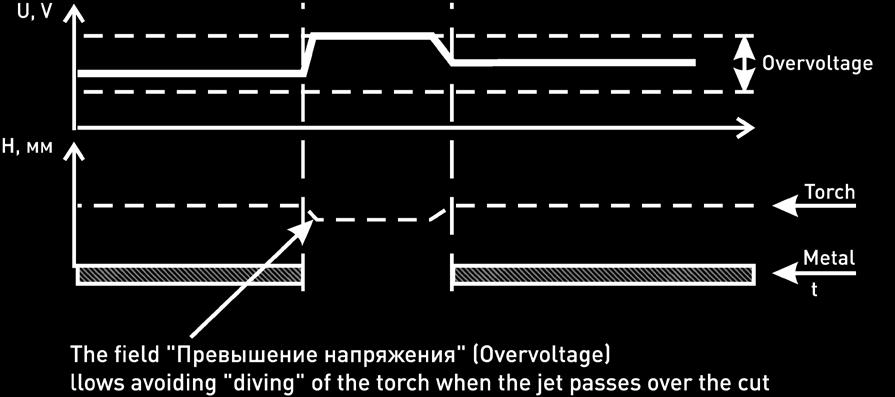
13 THC Control 2.0. Plasma Cutting System Control Software Fig. 2.4 Nozzle height Fig. 2.5 Overvoltage Rev
14 Minimum adjustment rate: in Mach3 it is known as «AntiDive». It sets minimum required torch speed in XY plane to enable adjustment. As mentioned previously, Mach3 decelerates the torch in turns, which results in growth of arc voltage and, consequently, possible lowering of the torch. To avoid it, the minimum limit of speed at which adjustment will be performed is introduced. If the current speed drops below this threshold, adjustment will be locked until the torch accelerates again. Important In the new screen set this parameter is set in mm/min, in legacy screen set it is set as percentage of maximum current feed rate (cutting rate) in XY plane. Low adjustment limit: minimum value of Z axis coordinates range during adjustment. High adjustment limit: maximum value of Z axis coordinates range during adjustment. Both parameters are set in mm. The parameter operation is illustrated in Fig Z adjustment rate: it is set in mm/min. Too high rate may result in omission of steps or axis jitter, while too low rate may result in slowness in surface monitoring. The parameter depends on material curvature and selected feed, so it is selected experimentally for each cutting mode. Important In the new screen set it is set in mm/min, and in the legacy one it is set as percentage of the maximum rate value Motor tuning on Z. Output voltage ratio: it is only used with LV input and sets the plasma machine output 8 (800)

 For this screen set operation mode it is supposed that the user has implemented the following control diagram: Z axis is controlled by Mach3 software (through PLCM series movement controller or")
15 THC Control 2.0. Plasma Cutting System Control Software Fig Low and high adjustment limits 2.2 GAS CUTTING WITH ADJUSTABLE Z AXIS IMPORTANT TO AVOID ACCIDENTS DURING GAS-OXYGEN CUTTING EQUIPMENT OPERATION, IT IS NECESSARY TO USE SAFETY HARDWARE (SAFETY GAS VALVES, DEVICES FOR CONTROLLING GAS-OXYGEN MIXTURE COMPOSITION IN IGNITION MODE, ETC.) For this screen set operation mode it is supposed that the user has implemented the following control diagram: Z axis is controlled by Mach3 software (through PLCM series movement controller or from LPT directly); Correction of position on Z axis with enabled adjustment is carried out via reading of UP and DOWN inputs (if UP input is active, then Mach3 sends command for moving the axis up, and if DOWN input is active, then the command for moving the axis down is sent. If the adjustment button is off, then UP/DOWN inputs are ignored). Movement along Z axis is only possible at active input ARC_OK (THC ON on tab Ports & Pins). To set up config, proceed as follows: Rev
16 1) On tab [Config]-[Ports&Pins]-[Output Signals] assign the preheating control output to Output3, and Z axis adjustment output to Output5. Specify the appropriate port and pins. 2) On tab [Config]-[Ports&Pins]-[Input Signals] enable inputs of signals «THC ON», «THC UP», «THC DOWN» and specify the respective port and pins (see Fig. 2. 7). The appearance of parameter library window in gas cutting mode with adjustable Z axis is illustrated in Fig Heating duration: The time necessary for preliminary heating of the metal to be cut before start of cutting, that is the time from heating flame valve opening till feed of cutting oxygen jet. Values of other parameters are described in item GAS CUTTING WITH STAND-ALONE AXIS Z MODULE IMPORTANT TO AVOID ACCIDENTS DURING GAS-OXYGEN CUTTING EQUIPMENT OPERATION, IT IS NECESSARY TO USE SAFETY HARDWARE (SAFETY GAS VALVES, DEVICES FOR CONTROLLING GAS-OXYGEN MIXTURE COMPOSITION IN IGNITION MODE, ETC.) For this screen set operation mode it is supposed that the user has implemented the following control diagram: Z axis control is assigned to an external controller (complete device which independently implements functions of maintaining a gap between the operating tool and the blank without involvement of Mach3); UP/DOWN inputs and THC ON (ARC OK) are not involved; 8 (800)


17 THC Control 2.0. Plasma Cutting System Control Software Fig Setup of adjustable Z axis gas cutting mode Parameter library Show processes All Select New Search by name Process parameters Name Save Delete Process type Cutting rate, mm\min Burning-through height, mm Burning-through duration, s Operating height, mm Heating duration, s Overlap processing height, mm Search rate, mm\min Search radius, mm Gas cutting External Z axis Min. rate for adjustment, mm\min Low adjustment limit, mm High adjustment limit, mm Speed рег Z. mm\min Export Import Nozzle height, mm Fig Parameter library window Rev
18 Mach3 Z axis can be controlled in «manual» mode using «Перемещение вверх» («Up Movement») and «Перемещение вниз» («Down Movement») outputs (once the button is pressed on the screen set, Mach3 activates the respective output. A stand-alone controller reads such an event and moves the axis until the button in the screen set is pressed again, and the input is deactivated). Pressing «Регулирование» («Adjustment») button activates the respective output, the stand-alone Z axis controller recognizes the event and switches over to maintaining the gap in automatic mode without involvement of Mach3. To use this mode, on tab [Config]- [Ports&Pins]-[Output Signals] activate the respective outputs Output4, Output6 and specify the port and pins (see Fig. 2. 9). The appearance of parameter library window in gas cutting mode with external Z axis is illustrated in Fig For detailed description of parameters see items 2. 1 and 2. 2 of this Manual. 03 Operation program start and stop display and control area This area is located at the top of the screen. It includes a group of cutting process controls (buttons, fields and indicators). The composition of the displayed controls depends on the selected cutting mode. 3.1 PLASMA CUTTING The appearance of the operation program start and stop display and control area in plasma cutting mode is shown in Fig (800)


19 THC Control 2.0. Plasma Cutting System Control Software Fig Setup of gas cutting with stand-alone axis Z module Fig The parameter library window for gas cutting process with external Z axis Rev
 [Связь c THC] (Communication with THC) indicator of communication with THC device.")
20 Fig Display and control area in plasma cutting mode The purpose of controls in the control area is explained below: 1) [Связь c THC] (Communication with THC) indicator of communication with THC device. 2) [ARC OK не исп./исп] (ARC OK is not used/used) button and indicator of ARC OK signal standby mode enabling and disabling after issue of the arc ignition command. 3) [Регулир.вкл/выкл] (Adjustment on/off) button and indicator of enabling and disabling of Z axis nozzle adjustment mode during G-code execution. 4) [Факел вкл/выкл] (Jet on/off) electric arc manual ignition button and its operation indicator. 5) [Напряжение текущее] (Current voltage) current electric arc voltage. 6) [Напряжение желаемое] (Desired voltage) required electric arc voltage value. If zero value is specified as the desired voltage, then immediately after control delay the controller records the current arc voltage and will maintain it till the end of cutting. 7) [Пауза] (Pause) suspend the control program execution. 8) [Стоп] (Stop) stop the control program execution. 9) [Пуск] (Start) control program start. 10) [Аварийный стоп] (Emergency stop) system emergency stop button (EStop). 8 (800)
21 THC Control 2.0. Plasma Cutting System Control Software Fig Display and control area in gas cutting mode with adjustable Z axis 3.2 GAS CUTTING WITH ADJUSTABLE Z AXIS Fig. 3 illustrates the appearance of the operation program start and stop display and control area in gas cutting mode with adjustable Z axis. 2. 1) [Прогрев вкл/выкл] (Pre-heating on/off) button and indicator of opening and closing of the valve feeding the gas mixture for blank preheating, it controls output Output3 Mach3. 2) [Факел выкл./вкл.] (Jet on/off) button and indicator of opening and closing of the valve feeding oxygen cutting jet. 3) [Корректировка вверх] (Correction up) THC Up input status indicator responsible for adjustment of the torch height. 4) [Корректировка вниз] (Correction down) THC Down input status indicator responsible for corrective lowering of the torch. Other controls are described in item 3. 1 of this Manual. 3.3 GAS CUTTING WITH STAND-ALONE AXIS Z MODULE Fig. 3 illustrates the appearance of the operation program start and stop display and control area in gas cutting mode with stand-alone Z axis module. 3. Rev
22 Fig Display and control area in gas cutting mode with adjustable Z axis 1) [Перемещение вверх] activation button and activity indicator of output Output4 responsible for the torch lifting. 2) [Перемещение вниз] (Move down) activation button and activity indicator of output Output4 responsible for the torch lowering. 04 Coordinate system calibration The «Калибровка системы координат» («Coordinate system calibration») screen is used to control parking positions, operating datum and coordinate system rotation angle. Fig. 4 illustrates the general appearance of this window. 1. All functional fields of «Калибровка системы координат» («Coordinate system calibration») window are listed below. 4.1 «КООРДИНАТЫ» («COORDINATES») SCREEN AREA The area contains controls necessary for primary setup of machine and operator coordinate system. Fig. 4 illustrates composition of the machine coordinate system controls. 2. [Аxis X, Y, Z, A] is the field displaying current torch coordinates (operator or machine coordinates, depending on the [Машинные координаты]) (Machine coordinates) button status. [Reset X, Y, Z, A] buttons for zeroing of current values of operator coordinates along X, Y, Z, A axes. 8 (800)
23 THC Control 2.0. Plasma Cutting System Control Software [Сброс всех осей] (Reset of all axes) simultaneous zeroing of all axes operator coordinate values. [Переезд на рабочий ноль] (Transfer to operating datum) movement of the torch to zero position on operator coordinates. [Машинные координаты] (Machine coordinates) enables and disables the machine coordinate display mode. [Автопоиск Z=0] a button starting the mode of material search along Z axis. [Ограничение габаритов] (Dimensional limitation) enables and disables the use of software displacement limitation mode («Soft Limits»), parameters of which are set up in menu Mach3 ([Config] - [Homing/ Limits]). To use this mode, it is necessary to set the maximum allowable torch movement coordinates along the respective axes in Soft Max and Soft Min fields. [Поиск базы и обнуление координат] (Datum search and zeroing of coordinates) starting a macro searching zero values of machine coordinates. To use the macro, end sensors must be available on axes, and they must be set up in options of Mach3 ([Config] [Ports & Pins]). 4.2 «ПАРКОВКА» («PARKING») SCREEN AREA Parking is displacement of the torch according to coordinates preset by the operator. It is most often used for the torch maintenance (replacement of consumables, nozzle cleaning, blank replacement). Fig. 4 illustrates the appearance and composition of the parking area controls. 3. [Отправить на парковку] Send to parking) sends the torch on machine coordinates specified in the respective fields manually or using button [Текущие координаты как парковочные] (Current coordinates as parking ones). [Текущие координаты как парковочные] (Current coordinates as parking ones) saves the current value of the torch machine coordinates as parking coordinates. Координаты парковки (Machine parking coordinates) displays the current value of machine parking coordinates. Rev

")
 555 63 74")
24 Fig Coordinate system calibration screen Fig «Координаты» («Coordinates») screen area Fig «Координаты» («Coordinates») screen area 8 (800)
25 THC Control 2.0. Plasma Cutting System Control Software 4.3 «ВЫРАВНИВАНИЕ СИСТЕМЫ КООРДИНАТ» («COORDINATE SYSTEM ALIGNMENT») FIELD If a sheet blank is located not in parallel with the operating coordinate system axis, the user may align the machine operator coordinate system based on one of the blank sides (Fig. 4. 4) in XY coordinate plane. The system is able to determine the necessary coordinate axes rotation angle based on two points located along a side of the blank. In this case the coordinate system will be aligned based on the coordinate system axis nearest to the blank side, i.e. the coordinate system will be rotated within ±45 of its initial position. The alignment procedure is described below: 1) Set zero alignment point, moving the torch in manual mode to the point nearest to the machine datum on the selected side of the sheet blank and pressing [Нулевая точка выравнивания] (Zero alignment point) button. 2) Move the torch to a point far from the machine datum on the same side of the sheet blank. The greater is the distance between the two points on the selected sheet side, the more precise will be the determined necessary coordinate system rotation angle. Press [Выравнивание системы координат] (Coordinate system alignment) button to calculate the coordinate system rotation angle and align the system. In this case the X and Y coordinate values will change their colour to red in the respective fields. 3) To cancel the coordinate system alignment on the sheet blank, press [Отмена выравнивания] (Cancel alignment) button. 4.4 FIELD «ВВОД G-КОДА» (G-CODE ENTRY) This screen area (Fig. 4. 5) contains a manual G-code entry line and [Ручное управление] (Manual control) button for enabling the manual torch movement mode using cursor keys (jogging mode). Rev
 screen area 05 Setting the cutting parameters The «Установка параметров реза» («Setting the current parameters») window also contains the basic parameters of the selected")

26 Fig «Выравнивание системы координат» (Coordinate system alignment) screen area Fig «Ввод G-кода» (G-code entry) screen area 05 Setting the cutting parameters The «Установка параметров реза» («Setting the current parameters») window also contains the basic parameters of the selected cutting process which where entered in the parameter library settings (see item 2). The operator can change the values of specified parameters manually to set up the cutting process precisely, save changes in the same process, create a new process based on the specified parameters and cancel any introduced changes by restoring the latest saved state of the settings. The composition of the displayed controls (cutting parameters) depends on the selected process type. 5.1 PLASMA CUTTING The appearance of plasma cutting process settings screen area is shown in Fig The detailed description of the shown parameters is provided in item 2 of this Manual. The user can change settings of parameters 8 (800)


27 THC Control 2.0. Plasma Cutting System Control Software Fig Display and control area in gas cutting mode with adjustable Z axis Fig The screen for setting the cutting parameters in gas cutting mode with a stand-alone Z axis module entering new values of parameters either directly to the respective fields, or using [+] and [-] buttons right and left of the parameter display field. The increment is set using the button on the right. Rev
28 [Сохранить процесс] (Save process) a button for calling the parameter library window with introduction of changes to the process settings. The operator must confirm saving of parameters by pressing [Сохранить] (Save) button in the window that appears. [Сохранить как новый] (Save as new) create a new process based on the current settings. [Отменить изменения] (Cancel changes) reset any settings entered before the latest saving. 5.3 GAS CUTTING WITH STAND-ALONE AXIS Z MODULE Fug. 5 illustrates the appearance of the window in gas cutting mode with a stand-alone Z axis module is illustrated in Fig The detailed description of the shown parameters is provided in item 2 of this Manual, and the purpose of the control buttons is described in item GAS CUTTING WITH ADJUSTABLE Z AXIS Fig. 5 illustrates the appearance of the window in gas cutting mode with adjustable Z axis. 3. The detailed description of the shown parameters is provided in item 2 of this Manual, and the purpose of the control buttons is described in item G-code operation The screen is designed for loading the control program, assessment of possible cutting results and changing the program according to the machine operator s needs. Fig. 6 illustrates the appearance of the window «Работа с G-кодом» (G-code operation). 1) [Открыть файл] (Open file) open the control program (G-code) file. 8 (800)
 [Редактор файлов] (File editor) open the used G-code in an external editor (Windows Notepad by default),")
29 THC Control 2.0. Plasma Cutting System Control Software Fig The screen for setting the cutting parameters in gas cutting mode with a adjustable Z axis 2) [Редактор файлов] (File editor) open the used G-code in an external editor (Windows Notepad by default), any introduced changes will be displayed in G-code field upon saving of the file in an external program. 3) [Закрыть файл] (Close file) close the control program file being used. 4) [Недавние файлы] (Recent files) call a window displaying all recently used G-code files. 5) [Строка] (String) a field for going to the desired G-code string number based on its number. 6) [В начало] (Home) go to the first G-code string. 7) [Запуск со строки] (Start from string) start execution of the control program from the current string. 8) [Обратный ход] (Back run) back run of the control program. 9) [Ввод G-кода] (G-code entry) a field for manual G-code entry. 10) [Обновить траекторию] (Update torch path) updating the torch path rendering after introduction of changes to the control program. 11) [Слежение за траекторией] (Torch path tracking) enabling the mode in which the display screen cursor will follow the torch path. Rev
 window contains controls necessary for monitoring and correction of the cutting parameters during G-code execution.")
30 Fig G-code operation screen 07 Manual control The «Ручное управление» («Manual control») window contains controls necessary for monitoring and correction of the cutting parameters during G-code execution. Fig. 7 illustrates the appearance of this window. 1. 1) The «Координаты» («Coordinates») field contains information about the current coordinates of X, Y, Z, A axes, and the current Z axis correction value and blank radius value if the blank is cylinder-shaped. The buttons [СбросX Y Z, А] (Reset X, Y, Z, A) are designed for zeroing of the current coordinates of the axes. 2) The field «Подача (скорость реза)» («Feed (cutting rate)» and «Ручное управление (jogging)» («Manual control (jogging)») displays the current displacement rate expressed in mm/min. The user can promptly redefine the current feed rate or jogging values during cutting using these buttons (as percentage of the rate values specified in settings or G-code). 3) The field «Траектория» («Torch path») contains a G-code entry field 8 (800)
31 THC Control 2.0. Plasma Cutting System Control Software Fig The screen of manual control of the cutting process in plasma cutting mode and functional buttons responsible for G-code operation: 6) [В начало] (Home) go to the first G-code string. 7) [Запуск со строки] (Start from string) start execution of the control program from the current string. 8) [Обратный ход] (Back run) back run of the control program. 9) [Ввод G-кода] (G-code entry) a field for manual G-code entry. 10) [Обновить траекторию] (Update torch path) updating the torch path rendering after introduction of changes to the control program. [Слежение за траекторией] (Torch path tracking) enabling the mode in which the display screen cursor will follow the torch path. Rev
 505-63-74 - Moscow +7 (473) 204-51-56 - Voronezh 394033, 160, Leninsky avenue, Voronezh, Russia Mon-Thu: 8.00 17.00 Fri: 8.00 16.00 Break: 12.30 13.")
32 Please, be aware that the documentation may be changed due to permanent technical improvement of the products. The latest versions are available for downloading from our web site www. purelog i c. r u Contacts +7 (495) Moscow +7 (473) Voronezh , 160, Leninsky avenue, Voronezh, Russia Mon-Thu: Fri: Break: info@purelogic.ru
Ether-Mach THC Guide. Features. Ether-Mach THC Usage and Customization. Product Brief. Ether-Mach : Ethernet Motion Controller THC Guide : 1.
 Ether-Mach THC Guide Ether-Mach THC Usage and Customization Features Provides THC UP/DOWN control of the Z axis with anti-dive. Supports common THC controllers (ex, Proma THC 150) Includes free modification
TMC3in1 Torch & Motion Controller 3in1. Vol. 04: FAQ and Troubleshooting Guide
 TMC3in1 Torch & Motion Controller 3in1 Plasma THC - 5 Axis Breakout Board Spindle Controller Vol. 04: FAQ and Troubleshooting Guide For use with TMC3in1 Plugin Rev: 4.2.x.x Author: Randall L Ray Very Sr.
Ultimate Screen Reference Guide
 MACHMOTION Ultimate Screen Reference Guide 8/11/2011 Everything you need to know to use and setup the MachMotion Ultimate Screen. MachMotion Version 1.0.2 2 P a g e Copyright 2011, MachMotion.com All rights
CommandCNC 1.1 Release Notes
 CommandCNC 1.1 Release Notes What's new in 1.1 Auto-Set support for DTHC...2 Fixture Offsets...7 User Interface Rework...11 Output buttons can now be customized... 12 Support for two more axes...14 New
COPYCAT NEW FANGLED SOLUTIONS 2/6/2009
 1.0 INTRODUCTION 1.1 CopyCat is a unique wizard used with MACH3. It is not a stand alone program. This wizard will allow you to jog a machine around and create a Gcode file from the movement. 2.0 REQUIREMENTS
Using the CNC Plasma Cutter (Torchmate)
") Using the CNC Plasma Cutter (Torchmate) Digital Media Lab Tutorial Written by: John Eberhart Create a Profile to Cut The Plasma Cutter reads DXF profiles. Create or open your profiles in Autocad and scale
Using the CNC Plasma Cutter (Torchmate) Digital Media Lab Tutorial Written by: John Eberhart Create a Profile to Cut The Plasma Cutter reads DXF profiles. Create or open your profiles in Autocad and scale
Trucut SeriesOne/XT. Operators Manual. SeriesOne and XT machines running Mach4 Software
 Trucut SeriesOne/XT Operators Manual SeriesOne and XT machines running Mach4 Software Table Of Contents Overview 1 1 Mach4 User Interface 2 1.1 Primary Function Screens 2 1.1.1 Program Run 3 1.1.2 Diagnostics
½ Caution! Introduction. Blind.switch 5701/1.0
 Blind.switch 5701/1.0 Introduction General information This software application enables you to program blind/switch actuators using manual mode (referred to below as actuator), control blind and roller
Software Manual. Version: H BENCHTOP ROBOT SOFTWARE USER GUIDE Version H
 Software Manual Version: H6.1.1.292 BENCHTOP ROBOT SOFTWARE USER GUIDE Version H6.1.1.293 Software Manual Table of Contents SECTION 1: INTRODUCTION... 5 1.1 Introduction...6 1.2 Safety...6 1.3 New Features...6
Conversational Programming for 6000i CNC
 Conversational Programming for 6000i CNC www.anilam.com P/N 634 755-22 - Contents Section 1 - Introduction Section 2 - Conversational Mode Programming Hot Keys Programming Hot Keys... 2-1 Editing Keys...
3D Body. Summary. Modified by Admin on Sep 13, Parent page: Objects
 3D Body Old Content - visit altium.com/documentation Modified by Admin on Sep 13, 2017 Parent page: Objects A sphere, a cylinder and 4 extruded rectangles have been used to create the 3D body for an LED.
Turning your ideas into reality Novakon MPG Manual
 Novakon MPG Manual The E-STOP switch button on your Novakon CNC Control Pendant only provides Emergency STOP signal to Mach3 CNC application. For further protection in CNC operation, other emergency protection
TRUCUTCNC MACH4 MANUAL. Mach4 Overview
 Mach4 Overview Mach4 is a robust and modern CNC control software package. Unlike Mach3, it was developed on modern 64 bit computer architecture. This means Mach4 performs better and faster on new PC s
IEEM 215. Manufacturing Processes I Introduction to the ARIX CNC milling machine
 IEEM 215. Manufacturing Processes I Introduction to the ARIX CNC milling machine The image below is our ARIX Milling machine. The machine is controlled by the controller. The control panel has several
Conversational Programming for 6000M, 5000M CNC
 Conversational Programming for 6000M, 5000M CNC www.anilam.com P/N 70000486F - Contents Section 1 - Introduction Section 2 - Conversational Mode Programming Hot Keys Programming Hot Keys... 2-1 Editing
Fagor Automation S. Coop. NV-10/11 NV-20/21 NV-300/301M. Operating Manual. Manual code: Manual version: 0410 Software version: 3.
 Fagor Automation S. Coop. NV-10/11 NV-20/21 NV-300/301M Operating Manual Manual code: 14460044 Manual version: 0410 Software version: 3.xx INDEX 1 Unit description...3 1.1 Front panel... 3 1.2 Rear panel
PLCM-B1 Breakout board for PLCM-E3/E3p controller
 www.purelogic.ru User manual CONTENTS: 1. General information... 2 2. Delivery set... 2 3. Technical specifications... 3 4. Key features... 4 5. Sockets purpose and indication... 6 6. Connection... 11
imach III P3A and P3A-E CNC Control Pendant
 www.vistacnc.com - 1 - imach III P3A and P3A-E CNC Control Pendant www.vistacnc.com - 1 - imach III P3A Pendant Manual v. 3.4 www.vistacnc.com - 2 - PREFACE Any machine tool, including computer controlled
Xbox gamepad CNC pendant user manual
 Patrik Tegelberg 2017-09-04 Xbox gamepad CNC pendant user manual Computer controlled manufacturing machines are awesome, and not designed for manual cutting. This controller, for LinuxCNC, maintains the
COMMANDCNC UPDATING INSTRUCTIONS AND NOTES
 COMMANDCNC UPDATING INSTRUCTIONS AND NOTES REV 1.0.3 Page 1 FILE LOCATIONS FOR COMMANDCNC Root (/) --- home --- * --- Documents --- Manuals --- --- Downloads --- firmware ---
Content. Content Ⅰ. Introduction of wiring of CNC router...2. Ⅱ.Install control software...2. Ⅲ. Introduction of Software...
 Content Content... 1 Ⅰ. Introduction of wiring of CNC router....2 Ⅱ.Install control software.....2 Ⅲ. Introduction of Software....5 Ⅳ. Description of software menus... 17 Ⅴ. Operation procedures...22 Ⅵ.Attachment:
SSII SUV MANUAL. LAGUNA TOOLS 2072 Alton Parkway Irvine, California Ph:
 SSII SUV MANUAL LAGUNA TOOLS 2072 Alton Parkway Irvine, California 92606 Ph: 800.234.1976 www.lagunatools.com 2018, Laguna Tools, Inc. LAGUNA and the LAGUNA Logo are the registered trademarks of Laguna
imach III P2-S CNC Control Pendant
 www.vistacnc.com - 1 - imach III P2-S CNC Control Pendant www.vistacnc.com - 1 - imach III P2-S Pendant Manual v. 3.3.0 www.vistacnc.com - 2 - PREFACE Any machine tool, including computer controlled machine
This document shows you how to set the parameters for the ModuleWorks Material Removal Simulation.
 Table of Contents Introduction:... 3 Select Profile:... 4 Tool Table - Create Tool(s)... 5 Tool properties:... 5 Tool Color R/G/B:... 6 Simulation Configurations - create stock... 7 What if plugin is greyed
TMC3in1 Torch & Motion Controller 3in1. Vol. 01: Hardware and Software Setup Guide
 TMC3in1 Torch & Motion Controller 3in1 Plasma THC - 5 Axis Breakout Board Spindle Controller Vol. 01: Hardware and Software Setup Guide For use with TMC3in1 Plugin Rev: 4.2.x.x Author: Randall L Ray Very
imach III P5A and P5A-E CNC Control Pendant
 www.vistacnc.com - 1 - imach III P5A and P5A-E CNC Control Pendant www.vistacnc.com - 1 - imach III P5A Pendant Manual v. 3.4.0 www.vistacnc.com - 2 - PREFACE Any machine tool, including computer controlled
6 Series Mill Controller Operation Manual
 6 Series Mill Controller Operation Manual Date: 2015/11/13 Version: 1.3 2 Contents 1 Function Key and System Configuration... 4 1.1 Main Screen Sections... 4 1.2 CNC System Configuration... 5 1.3 Coordinate...
Operator Manual. SeriesOne and XT Machines. RC Enterprises (615)
") Operator Manual SeriesOne and XT Machines RC Enterprises www.trucutcnc.com (615) 290-6260 TABLE OF CONTENTS CHAPTER 1 - OPERATOR INTERFACE... 1 1.1 PROGRAM RUN... 1 1.1.1 Code Window... 1 1.1.2 MDI Code
Operator Manual SeriesOne and XT Machines RC Enterprises www.trucutcnc.com (615) 290-6260 TABLE OF CONTENTS CHAPTER 1 - OPERATOR INTERFACE... 1 1.1 PROGRAM RUN... 1 1.1.1 Code Window... 1 1.1.2 MDI Code
imach III P4-S and P4-SE CNC Control Pendant
 www.vistacnc.com - 1 - imach III P4-S and P4-SE CNC Control Pendant www.vistacnc.com - 1 - imach III P4-S Pendant Manual v. 4.0 www.vistacnc.com - 2 - PREFACE Any machine tool, including computer controlled
6 Series Mill Controller Operation Manual
 6 Series Mill Controller Operation Manual Date: 2013/10/25 Version: 1.1 Contents 1 Function Key and System Configuration... 4 1.1 Main Screen Sections... 4 1.2 CNC System Configuration... 5 1.3 Coordinate...
Geeetech Aluminum Prusa I3. User Manual
 Geeetech Aluminum Prusa I3 User Manual 1 Safety Instructions Building the printer will require a certain amount of physical dexterity, common sense and a thorough understanding of what you are doing. We
DP200/DP201/DP102 Series. Slicer Program Manual
 DP200/DP201/DP102 Series Slicer Program Manual Read the User Manual before operating the product, and keep the manual at a convenient place near the product. Contents 1. Slicer Program Manual-----------------------------------------------------------------------------------------------------3
How to Make a Sign. Eagle Plasma LLC. Accessing the included step by step.dxf files
 Eagle Plasma LLC How to Make a Sign Accessing the included step by step.dxf files The following tutorial is designed to teach beginners, screen by screen, to create a simple sign project. In this lesson
SALECNC CNC ROUTER. User s Operation Manual (NC-Studio Program) SaleCNC.com By: AutomationMaker
 SaleCNC.com By: AutomationMaker") SALECNC CNC ROUTER User s Operation Manual (NC-Studio Program) SaleCNC.com By: AutomationMaker 1 Content Content... 1 Ⅰ. Introduction of wiring of CNC router....2 Ⅱ.Install control software.....2 Ⅲ. Introduction
SALECNC CNC ROUTER User s Operation Manual (NC-Studio Program) SaleCNC.com By: AutomationMaker 1 Content Content... 1 Ⅰ. Introduction of wiring of CNC router....2 Ⅱ.Install control software.....2 Ⅲ. Introduction
Wizard 1000 REFERENCE MANUAL
 Wizard 1000 REFERENCE MANUAL W1000 Key Layout Display Area Axis Keys Numeric Keypad Clear key Soft keys Enter key Power Indicator light Arrow keys - Up/ Down arrow keys are also used to adjust the screen
Ether-Mach Mach3 Plugin Guide
 Ether-Mach Mach3 Plugin Guide Ethernet Motion Controller for Artsoft's Mach3 CNC. Features Connects over a dedicated 100 Mbps Ethernet connection. Smooth motion on 6 coordinated axes plus a spindle motor.
Notes on safety: Improper use or disregard of these warnings may result in the injury or death of people.
 Notes on safety: Improper use or disregard of these warnings may result in the injury or death of people. Do not, in any manner, process, take apart, or make changes to this product. When installing this
For the latest information about this machine (including manuals), see the Roland DG Corp. website (http://www.rolanddg.com).
, see the Roland DG Corp. website (http://www.rolanddg.com).") VPanel is a program to operate the modeling machine on the computer screen. It has functions to output cutting data, perform maintenance, and make various corrections. In addition, it displays error messages
VPanel is a program to operate the modeling machine on the computer screen. It has functions to output cutting data, perform maintenance, and make various corrections. In addition, it displays error messages
UNIT 11: Revolved and Extruded Shapes
 UNIT 11: Revolved and Extruded Shapes In addition to basic geometric shapes and importing of three-dimensional STL files, SOLIDCast allows you to create three-dimensional shapes that are formed by revolving
INSTALLING THE WINDOWS-BASED DRIVER NOTICE!
 INSTALLING THE WINDOWS-BASED DRIVER NOTICE! Keep the machine and the computer unconnected until you carry out this installation operation. Failure to follow the correct procedure may make installation
Standard Mach4 Features included with Tangential:
 MACH4 TANGENTIAL Tangential takes place on one page: Program Run. The Tangential Profile is intended to operate Machinery equipped with a rotational axis independent of, but usually associated in, the
PLCM-E1b CNC Ethernet controller
 PLCM-E1b CNC Ethernet controller INSTRUCTION MANUAL 01. General information 02. Delivery set 03. Technical features 04. Main connectors and indicators 05. Software installation 06. Terms of Warranty 2
REMOTE CONTROL OPERATION INSTRUCTIONS
 INSTRUCTIONS The Proflame 2 (STL-411-506) is used with SIT valve components starting with Serial # 13001. If you have a unit manufactured prior to the change, please use STL-208 remote control and refer
Naturela Smart Home system
 Naturela Smart Home system User interface for work with controllers NPBC-V3C-xx, used in pellet burners, fireplaces, stoves, and boilers User Manual In order to learn how to work with the Naturela Smart
Craftsman CNC. LinuxCNC. Custom developed for Craftsman CNC Routers
 Craftsman CNC LinuxCNC Custom developed for Craftsman CNC Routers Menu File Load gcode Load a gcode program Recent gcode Shows the 10 most recently opened gcode programs Close gcode Closes the current
FIREPOWER M04 RGB MMO LASER MOUSE INSTRUCTION MANUAL ADXLM0418
 FIREPOWER M04 RGB MMO LASER MOUSE INSTRUCTION MANUAL ADXLM0418 Contents Safety Warnings... 4 Unpacking... 5 Product Overview... 6 Adjusting the Weight... 7 System Requirements... 8 Software Installation...
FAGOR AUTOMATION MC TRAINING MANUAL
 FAGOR AUTOMATION MC TRAINING MANUAL ACER MC TRAINING MANUAL 8 holes 1/2" depth grid pattern R0.125 1.5 6 unit: inch R0.25 4 1.25 2 2.675 1/2" depth rectangular pocket 1/2" depth circular pocket R0.75 8
2017 DIY Controls for a CNC Plasma Cutting Table
 2017 DIY Controls for a CNC Plasma Cutting Table Plug and play controls for a CNC plasma cutting table have greatly increased in cost over the past few years due to Microsoft no longer supporting Windows
Conversational Programming for 6000M, 5000M CNC
 Conversational Programming for 6000M, 5000M CNC www.anilam.com P/N 70000486E - Warranty Warranty ANILAM warrants its products to be free from defects in material and workmanship for one (1) year from date
NC LASER CUTTING MACHINE
 NC LASER CUTTING MACHINE OPERATION INSTRUCTION MANUAL IMPORTANCE Operate, check and maintain this machine after reading this instruction manual and the manual concerned with attached device and then understanding
300S READOUTS REFERENCE MANUAL
 300S READOUTS REFERENCE MANUAL 300S Key Layout 1 Display Area 2 Soft keys 3 Power Indicator light 4 Arrow Keys: Use the UP/DOWN keys to adjust the screen contrast. 5 Axis Keys 6 Numeric Keypad 7 ENTER
Application program: description and examples
 F a n C o i l U n i t C o n t r o l l e r F a n C o i l 4 9 5 5 1 Application program: description and examples Woertz AG Electrotechnical accessories, installation systems Hofackerstrasse 47, P.O. Box
28 FUNCTION Hand Control w/ 4 Quadrant Jog Stick Copyrighted CandCNC 2007 all rights reserved
 28 FUNCTION Hand Control w/ 4 Quadrant Jog Stick MPG101B Mill/Router MPG101B Torch/THC SETUP and OPERATION MANUAL REV1 Copyrighted CandCNC 2007 all rights reserved MPG101B FEATURES LIST: Low Profile Light
Our thanks go to: Puppy Linux, RTAI, EMC, axis, all the kernel developers and big mama thornton.
 CoolCNC Linux First Steps This manual is a step by step introduction for the installation of the CoolCNC Linux Live CD. Its intent is to lead to a better understanding of the current processes. This document
2000 Series Mill / Router Operating Manual
 2000 Series Mill / Router Operating Manual 1. Introduction 1.1 Control Startup To open the control software double-click on the profile icon on the desktop. Control Icon 1.2 Overview This manual gives
Software designed to work seamlessly with your CNC Masters machine. Made to work with Windows PC. Works with standard USB
 Software designed to work seamlessly with your CNC Masters machine Made to work with Windows PC Works with standard USB Clutter free interface. The software is engineered for the machine so you don t have
Using the Android teach-pad
 with ROBWIN 7 and ROBOFORTH II v15/16 Components The components of the system are: 7 inch hand-held tablet Android software (apk or app ) already loaded. Bluetooth adaptor Serial port on rear of controller
13 Vectorizing. Overview
 13 Vectorizing Vectorizing tools are used to create vector data from scanned drawings or images. Combined with the display speed of Image Manager, these tools provide an efficient environment for data
imach III M2 CNC Control Pendant
 www.vistacnc.com - 1 - imach III M2 CNC Control Pendant www.vistacnc.com - 1 - imach III M2 Pendant Manual v. 1.1 www.vistacnc.com - 2 - PREFACE Any machine tool, including computer controlled machine
RobWin7 instruction manual
 Using ROBWIN v7.1.14 with ROBOFORTH II v13x up RobWin Sands Technology International; This is a Windows based application which runs in the computer. It communicates with the robot controller and also
Asyfeed Module. User Guide. Document
 Document Asyril_MODULE_ASYFEED_User_Guide_EN 000.100.511 Version D1 Date 06.04.2018 Table of Contents Table of Contents TABLE OF CONTENTS... 2 1. INTRODUCTION... 4 1.1. GENERALITIES... 4 1.2. RELATED MANUALS...
Brief instructions. ERSA soldering station
 ERSA soldering station Contents 1. Introduction... 3 1.1 Explanation of symbols... 3 2. Commissioning... 4 2.1 Unpacking the soldering station... 4 2.2 Placing the soldering station for work... 4 3. Functional
Conversational Programming for 6000i CNC
 Conversational Programming for 6000i CNC January 2008 Ve 01 634755-21 1/2008 VPS Printed in USA Subject to change without notice www.anilam.com P/N 634755-21 - Warranty Warranty ANILAM warrants its products
User Manual. (DSP5.3 For MPC6515) V1.2
 V1.2") 1 User Manual (DSP5.3 For MPC6515) V1.2 2 Chapter 1 Installation of the system 1.1 Contents of the system 4 1.2 Requirement of PC 4 1.3 Installation of MPC6515 card 4 1.4 Installation of the software 4
1 User Manual (DSP5.3 For MPC6515) V1.2 2 Chapter 1 Installation of the system 1.1 Contents of the system 4 1.2 Requirement of PC 4 1.3 Installation of MPC6515 card 4 1.4 Installation of the software 4
Trio Application Control System Instruction Sheet
 Trio Application Control System Instruction Sheet P/N 7580708_01 CAUTION The procedures detailed within this guide should only be performed by trained Nordson personnel or by persons cleared to do so by
MISUMI SUPPORT SOFTWARE. RS-Manager. User s Manual C1 / C21 / C22 / P1 EXWM KE114. Ver. 2.00
 MISUMI SUPPORT SOFTWARE RS-Manager User s Manual C1 / C21 / C22 / P1 Ver. 2.00 EXWM14200 KE114 CONTENTS RS-Manager User s Manual Before getting started 1 1. About RS-Manager 2 2. Installing and uninstalling
imach III P1A-S CNC Control Pendant
 www.vistacnc.com - 1 - imach III P1A-S CNC Control Pendant www.vistacnc.com - 1 - imach III P1A-S Pendant Manual v. 3.3.1 www.vistacnc.com - 2 - PREFACE Any machine tool, including computer controlled
CNC Knife. VCarve Pro V8 Software Setup for CNC Knife Jobs:
 CNC Knife VCarve Pro V8 Software Setup for CNC Knife Jobs: 1. 2. Run VCarve Pro V8 (Note: VCarve Pro V7 - Shopbot Edition will NOT work) Choose File->Open and select the.dxf file that contains the lines
MRZJW3- SETUP154E. General-Purpose AC Servo Servo Configuration Software MODEL INSTALLATION GUIDE
 General-Purpose AC Servo Servo Configuration Software MODEL MRZJW3- SETUP154E INSTALLATION GUIDE Thank you for choosing the Mitsubishi general-purpose AC servo Servo Configuration Software. To optimize
Jet Cutting Setup and Operation Manual
 Jet Cutting Setup and Operation Manual v6.1.38 Introduction Welcome to SheetCam, an affordable but powerful 2 1/2 D CAM program. SheetCam has been designed to fill a niche in the CAM marketplace by providing
INSTRUCTION MANUAL R.S.ENTERPRISES BANGALORE
 R S ENTERPRISES #12/90,1 st MAIN ROAD, NEW KALAPPA BLOCK, RAMACHANDRA PURAM, BANGALORE 560 021, KARNATAKA, INDIA, EMAIL: - rsentblr@yahoo.co.in Phone: - 080-23122201 mobile: - 0 9448382201. 1 INSTRUCTION
ADT-HC4200/4300 Flame/Plasma Controller. Copyright
 HC4200/4300 CNC Flame/Plasma Controller User Manual ADTECH (SHENZHEN) CNC TECHNOLOGY CO., LTD 5th Floor, 27-29th Building, Tianxia IC Industrial Park, Yiyuan road, Nanshan District, Shenzhen Post code:
Geeetech Duplicator 5 3D printer. User Manual
 Geeetech Duplicator 5 3D printer User Manual Contents Safety Instructions... 4 1.Software Resources... 5 1.1 Repetier-Host... 5 1.2 Driver... 5 1.3 Arduino IDE... 6 2.Connect the Printer... 6 3.Printer
L3 Series Software for Material Testing
 L3 Series Software for Material Testing Performing a Test The Better Solution Table of Contents Page 4.0 performing an L3 Test 4 4.1 L3 Test Modes of Operation 4 4.1.1 Standard Operating Mode 4 4.1.2
Trouble Shooting Leveling Control Box Electric Jacks. Touch Pad LED Probable Cause Solution
 Trouble Shooting Leveling Control Box 140-1224 Electric Jacks Copyright Power Gear Issued: January 2013 #82-L0524, Rev. OA Touch Pad LED Probable Cause Solution 1. On/Off LED will not light 2. Wait LED
USBCNC PLASMA CONTROL with icnc600 or External device (Proma) PLASMA USERMANUAL
 PLASMA USERMANUAL") USBCNC PLASMA CONTROL with icnc600 or External device (Proma) PLASMA USERMANUAL Document Release 1.3 Published by: Bert Eding Eindhoven The Netherlands Title: USBCNC Plasma user manual Author: Bert Eding
USBCNC PLASMA CONTROL with icnc600 or External device (Proma) PLASMA USERMANUAL Document Release 1.3 Published by: Bert Eding Eindhoven The Netherlands Title: USBCNC Plasma user manual Author: Bert Eding
SeeTool - Solutions for KNX
 SeeTool - Solutions for Office building segment Application 3.0.0.0.0.4 Movement dependent automatic light control, 2 room solution Lighting control functions The light is automatically switched ON when
Repetier-Host Documentation for use with Kora Pro 3D PC
 Repetier-Host Documentation for use with Kora Pro 3D PC Installation Prerequisites Before you start with the installation, you should check if your computer meets the requirements. Currently available
Table of Contents. Part I USB Communication. Part II User Interface. Part III User Settings (Tab Control) DFS-1000 Dataview. 2 File Menu.
 DFS-1000 Dataview. 2 File Menu.") 2 Table of Contents Part I USB Communication 3 1 Important... Information 3 2 Connecting... Controller 3 Part II User Interface 4 1 Overview... 4 2 File Menu... 5 3 Options... Menu 6 4 Help Menu... 6 5
2 Table of Contents Part I USB Communication 3 1 Important... Information 3 2 Connecting... Controller 3 Part II User Interface 4 1 Overview... 4 2 File Menu... 5 3 Options... Menu 6 4 Help Menu... 6 5
ND 7000 Demo. User s Manual. Digital Readout
 ND 7000 Demo User s Manual Digital Readout English (en) 11/2018 Contents Contents 1 Fundamentals...7 2 Software installation...11 3 Basic operation... 17 4 Software configuration... 43 5 Milling Quick
7/21/2009. Chapters Learning Objectives. Fillet Tool
 Chapters 12-13 JULY 21, 2009 Learning Objectives Chapter 12 Chapter 13 Use the FILLET tool to draw fillets, rounds, and other rounded corners. Place chamfers and angled corners with the CHAMFER tool. Separate
1 - Spedo 2100TRO Operators Manual Spedo UK Limited
 OPERATORS MANUAL Issue 2 Part Number SP005 233 Unit 5, Riverwey Ind. Park Newman Lane Alton Hampshire GU34 2QL ENGLAND Telephone National: 01420 86546 International: +44 1420 86546 Facsimile National:
WR-48 ROUTER TABLE HAND HELD CONTROL
 OPERATOR S MANUAL WR-48 ROUTER TABLE HAND HELD CONTROL Baileigh Industrial, Inc. P.O. Box 3 Manitowoc, WI 422-03 Phone: 920.684.4990 Fax: 920.684.3944 sales@baileighindustrial.com REPRODUCTION OF THIS
REV 1. Quick Start Guide. MBE Control Solutions
 Quick Start Guide MBE Control Solutions AMBER Setup AMBER is usually sold preinstalled on a Windows 7-64 Workstation. A Self installation guide and installation software is available from MBE Control Solutions:
ADT-HC4500 CNC Flame/Plasma Controller. Copyright
 ADT-HC4500 CNC Flame/Plasma Controller User Manual ADTECH (SHENZHEN) CNC TECHNOLOGY CO., LTD 5th Floor, 27-29th Building, Tianxia IC Industrial Park, Yiyuan road, Nanshan District, Shenzhen Post code:
Dreamer Series User Manual
 Dreamer Series User Manual Welcome to the world of the Dreamer. To ensure that you have the best possible user experience, it s important that you follow this user manual. Let s get started! In Parts I
ProTool DriveLine. Software User manual 375/16
 ProTool DriveLine Software User manual 375/16 Table of contents 1 General Information... 3 1.1 Documentation...3 1.2 Disclaimer...3 1.3 Trademarks...3 1.4 System requirements...3 2 About ProTool DriveLine...
ccassembler 3.1 Getting Started
 ccassembler 3.1 Getting Started Dated: 31.03.2017 www.cadclick.de - 1 - KiM GmbH 1 Basic Principles... 6 1.1 Installing anchor on anchor... 6 1.2 Modes and Actions... 7 1.3 Mouse control and direct input...
FARO Scanning Plugin
 FARO Scanning Plugin for Geomagic Studio 6 service release 4, Geomagic Qualify 6 service release 2, and Geomagic Qualify 7 Document version B Copyright 2004, Raindrop Geomagic, Inc. The FARO scanner is
User s Manual. Touch Panel Driver. Important
 User s Manual Touch Panel Driver Important Please read the Precautions and this User s Manual carefully to familiarize yourself with safe and effective usage. The software described in this document is
FlowNEST User s Guide. M-323 Version 6.0
 FlowNEST User s Guide M-323 Version 6.0 FLOWMASTER FlowNEST User's Guide Due to continuing product improvement, the information contained in this document is subject to change without notice. Flow International
Color Touchscreen Users Manual
 PROFESSIONAL ENGRAVING SYSTEMS Color Touchscreen Users Manual For all rotary engraving systems equipped with the color touchscreen For use with VCS release version 121-127 GENERAL INFORMATION The touch
Publication Number spse01695
 XpresRoute (tubing) Publication Number spse01695 XpresRoute (tubing) Publication Number spse01695 Proprietary and restricted rights notice This software and related documentation are proprietary to Siemens
USER MANUAL. ADS Animated Deflection Shapes
 USER MANUAL ADS Animated Deflection Shapes Version: June 24, 2015 Content: Introduction...3 Installation...4 Quick start guide...5 Example the grinder... 5 Creating of the model in ADS software... 5 Viewing
ideamaker Manual
 ideamaker Manual Using ideamaker... 2 Basic information... 2 What is ideamaker?... 2 Where to download ideamaker?... 2 Install ideamaker... 3 Let s Print!... 6 How to use ideamaker?... 23 Interface...
Repetier-Host Documentation
 Repetier-Host Documentation Installation Prerequisites Before you start with the installation, you should check if your computer meets the requirements. Currently available computers should have no problems
5 Programming and testing
 Running LoadIdentify To start the load identification service routine you must have an active program in manual mode and the tool and payload that you want to identify must be defined and active in the
Laser Machine User Manual:
 Laser Machine User Manual: OPERATOR ( EasyCut / LaserCut version 5.3 ) v1.0 CTR Laser Machine Operator Manual ( EasyCut version 5.3 ) ~ version 1.0 1 CONTENTS Section 1: Tutorials...5 1.1. How to Cut with
MillCAM Designer 2 User Manual.
 Total Commitment to Education and Training WorldWide. MillCAM Designer 2 User Manual. Denford Limited reserves the right to alter any specifications and documentation without prior notice. No part of this
Ishida Label Editor USER GUIDE
 Ishida Label Editor USER GUIDE ISHIDA CO., LTD Copyright 2000 Ishida Co. Ltd., Japan Copyright 2000 Interface Translation Ltd., New Zealand No part of this manual may be reproduced or transmitted in any