Sockets and accessories for auxiliary relays
|
|
|
- Abraham Brooks
- 6 years ago
- Views:
Transcription


1 ÍNDEX Sockets and accessories for auxiliary relays User manual Sockets and accessories for auxiliary relays User manual 1
2 Rev: 8 Date: 09/08/2016 ARTECHE Power Grid, S.L. This document, including texts, photos, graphics and any other content, is protected from unauthorized use under international copyright law. Any unauthorized copying, downloading, republication, or other use of the referenced material, without the prior written authorization of ARTECHE is strictly prohibited. The information in this document is subject to change without notice and should not be considered as a commitment by ARTECHE.
3 Chapter 1. Purpose... 4 Chapter 2. Acceptance and storage... 4 Chapter 3. Type description OP socket with front screw or faston connections (IP20) OP socket with front screw or faston connections (IP10) OP socket with front clamp connections (IP20) OP socket with rear screw connections or faston connections (IP10) OP socket with rear flush mounting screw or faston No OP sockets Chapter 4. Installation Sockets installation on DIN rails Spacing between sockets For OP relays (contactors and impulse relays included): For latching relays (No OP): Installation on DIN rail: Installation I size relay in a flush mounting socket: Relay positioning Relay connection Cover fixation Cable connections Chapter 5. Retaining clips Chapter 6. Security pins Chapter 7. Tests... 27
4 PURPOSE Chapter 1. Purpose The purpose of this user manual is to help the user to define, fit and use the sockets for ARTECHE auxiliary relays. Chapter 2. Acceptance and storage The sockets have been dispatched in boxes with packaging that guarantees their protection during normal handling for this type of equipment. If they are not to be installed immediately, it is recommended that they remain in their packaging, perfectly closed and in interior environmental conditions away from pollution, rain, dust, vibration, etc. If the packaging has been damaged or there is doubt over breakage due to incorrect handling during transport, this must be reported quickly (less than three days) to the carrier, to the relevant insurance company and to the factory. Also check that the material received matches the data on the order. Chapter 3. Type description The sockets are classified according to 4 criteria: a. Size of relay (D, F, J, I) b. Installation type (DIN rail or front connection, rear and flush mounting) c. Type of connections (screw, faston, double faston and clamp) d. Degree of protection (IP 10, IP 20) There are currently two families of sockets, those for the updated design developed by ARTECHE in 2005, called "OP" from now on and sockets for the previous design, called NO OP. The following tables show the OP and NO OP sockets in the ARTECHE range classified according to the four criteria described above. For bases mounted on DIN rails with front connections, there are two options according to the degree of protection for the terminals, called IP 10 and IP 20, according to the degree of protection. In case of cage clamp sockets, rear and/or flush mounting, the degree of protection for the terminals, is fixed. Sockets and accessories for auxiliary relays User manual 4
")

 CF RBF RJ OP TDJ OP VDJ30 OP RJS4 OP")

 2,5mm 2 1 2,5mm 2 1 2,5mm 2 1 2,5mm 2 1")

5 TYPE DESCRIPTION 3.1. OP socket with front screw or faston connections (IP20) SOCKET DIMENSIONS INTERNAL CONNECTIONS (Top view) FIX DRILLING RELAYS RD OP DD-10 OP CD DN-DE-IP20 DN-DE2C-IP20 (*) RF OP TDF OP VDF10 OP BF FN-DE-IP20 FN-DE2C IP20 (*) CF RBF RJ OP TDJ OP VDJ30 OP RJS4 OP JN-DE-IP20 JN-DE2C IP20 (*) BJ CJ TERMINAL TYPE MAX. WIRE SECTION QUANTITY FORK TERMINAL LOCKING TERMINAL CABLE PIN TERMINAL BLADE TERMINAL WIRE DOUBLE FASTON 4,8 x 0,5 (*) 2,5mm 2 1 2,5mm 2 1 2,5mm 2 1 2,5mm 2 1 0,2 2,5mm2 2 2,5mm 2 2 (*) The double faston terminal can be used only in models marked with an asterisk. Sockets and accessories for auxiliary relays User manual 5
6 TYPE DESCRIPTION Recommended torque for screwed sockets: Connection type Screw Recommended tightening torque 1Nm Screwdriver type Philips Pozi Flat Sockets and accessories for auxiliary relays User manual 6

 FIX DRILLING RELAYS RD")

 CJ TERMINAL")


7 TYPE DESCRIPTION 3.2. OP socket with front screw or faston connections (IP10) SOCKET DIMENSIONS INTERNAL CONNECTIOS (Top view) FIX DRILLING RELAYS RD OP DD-10 OP CD DN-DE IP10 DN-DE2C IP10 (*) RF OP TDF OP VDF10 OP BF CF FN-DE IP10 RBF FN-DE2C IP10 (*) RJ OP TDJ OP VDJ30 OP RJS4 OP BJ JN-DE IP10 JN-DE2C IP10 (*) CJ TERMINAL TYPE MAX. WIRE SECTION QUANTITY ROUND TERMINAL FORK TERMINAL LOCKING TERMINAL CABLE PIN TERMINAL BLADE TERMINAL 2,5mm 2 2 6,0mm 2 2 2,5mm 2 2 2,5mm 2 2 2,5mm 2 2 Sockets and accessories for auxiliary relays User manual 7
8 TYPE DESCRIPTION TERMINAL WIRE DOUBLE FASTON 6,35 x 0,8 (*) 0,2 4,0mm 2 2 2,5mm 2 2 (*)The double faston terminal can be used only in models marked with an asterisk. Recommended torque for screwed sockets: Connection type Screw Recommended tightening torque 1Nm Screwdriver type Philips Pozi Flat Sockets and accessories for auxiliary relays User manual 8
 SOCKET DIMENSIONS INTERNAL")

 TIP ISOLATE TERMINAL TIP WITHOUT ISOLATE TERMINAL 0,08-2,5mm 2 1+1")
 ELECTRICAL")
9 TYPE DESCRIPTION 3.3. OP socket with front clamp connections (IP20) SOCKET DIMENSIONS INTERNAL CONNECTIOS (Top view) FIX DRILLING RELAYS RF OP TDF OP VDF10 OP BF CF F DE CL IP20 RBF TERMINAL TYPE MAX. WIRE SECTION. QUANTITY RIGID (Stripped wire length: 5 6mm) FLEXIBLE (Stripped wire length: 5 6mm) TIP ISOLATE TERMINAL TIP WITHOUT ISOLATE TERMINAL 0,08-2,5mm ,08-2,5mm ,25-1,5mm ,25-2,5mm2 1+1 (Recommended tool by clamp connector supplier: flat screwdriver 0,4 x 3,5mm maximum) ELECTRICAL CONNECTIONS (2 holes on the terminal block for each connection) : Sockets and accessories for auxiliary relays User manual 9

 BASE")
 FIX DRILLING IP")


10 TYPE DESCRIPTION 3.4. OP socket with rear screw connections or faston connections (IP10) BASE DIMENSIONS INTERNAL CONNECTIONS (Top view) FIX DRILLING IP RELAYS 10 RD OP DD-10 OP CD 10 RF OP TDF OP VDF10 OP BF CF RBF 10 RJ OP TDJ OP VDJ30 OP RJS4 OP BJ CJ TERMINAL TYPE MAX. WIRE SECTION. QUANTITY FORK TERMINAL LOCKING TERMINAL CABLE PIN TERMINAL BLADE TERMINAL WIRE DOBLE FASTON 4,8 x 0,5 (*) 2,5mm 2 1 2,5mm 2 2 2,5mm 2 2 2,5mm 2 2 0,2 2,5mm 2 2 2,5mm 2 2 Sockets and accessories for auxiliary relays User manual 10
11 TYPE DESCRIPTION (*)The double faston terminal can be used only in models marked with an asterisk. Recommended torque for screwed sockets: Connection type Screw Recommended tightening torque 1Nm Screwdriver type Philips Pozi Flat Sockets and accessories for auxiliary relays User manual 11

 F EMP TR OP: TDF OP VDF10 OP RBF BF F EMP TR")
 J EMP TR OP: TDJ OP VDJ30 OP BJ CJ")
 I")


12 TYPE DESCRIPTION 3.5. OP socket with rear flush mounting screw or faston SOCKET DIMENSIONS INTERNAL CONNECTIONS (Top view) FIX DRILLING IP RELAYS (**) F EMP TR OP: TDF OP VDF10 OP RBF BF F EMP TR BF4RP OP BF4RP F EMP TR CORTA OP: RF OP CF F EMP TR CORTA RF OPXXX1X RF4 OPXXX1X (**) J EMP TR OP: TDJ OP VDJ30 OP BJ CJ J EMP TR RJS4 OP RJS4 OP J EMP TR BJ8RP OP BJ8RP J EMP TR CORTA OP: RJ J EMP TR CORTA RJ OPXXX1X RJ8 OPXXX1X (**) I EMP OP BI RI (**) Protection degree of the OP flush mounting socket with the panel installation: F EMP TR OP, F EMP TR CORTA OP, J EMP TR OP y J EMP TR CORTA OP: IP40 F EMP TR BF4RP OP, F EMP TR CORTA RF OPXXX1X, J EMP TR RJS4 OP, J EMP TR BJ8RP OP y J EMP TR CORTA RJ OPXXX1X: I EMP TR OP e I EMP TR BI16RP OP: IP30 IP20 TERMINAL TYPE MAX. WIRE SECTION. QUANTITY FORK TERMINAL LOCKING TERMINAL CABLE PIN TERMINAL BLADE TERMINAL 2,5mm 2 1 2,5mm 2 2 2,5mm 2 2 2,5mm 2 2 Sockets and accessories for auxiliary relays User manual 12
13 TYPE DESCRIPTION TERMINAL WIRE DOBLE FASTON 4,8 x 0,5 (*) 0,2 2,5mm 2 2 2,5mm 2 2 (*)The double faston terminal can be used only in models marked with an asterisk. Recommended torque for screwed sockets: Connection type Screw Recommended tightening torque 1Nm Screwdriver type Philips Pozi Flat Sockets and accessories for auxiliary relays User manual 13
14 TYPE DESCRIPTION 3.6. No OP sockets Sockets and accessories for auxiliary relays User manual 14
15 TYPE DESCRIPTION Only available I size sockets Sockets and accessories for auxiliary relays User manual 15


16 INSTALLATION Chapter 4. Installation The previous section defined both the sizes of the various types of sockets and the cut-outs for rear and flush mounting sockets and the spacing between fixing holes. The following gives a series of recommendations for installing the sockets in panels or cabinets Sockets installation on DIN rails The front sockets are easily mounted on DIN rails, as follows: 1. Insert the lower tabs on the socket on the lower part of the DIN rail as shown in figure below. 2. Fully fit the socket on the lower part of the DIN rail and press lightly and horizontally so that the socket is fixed to the rail by the upper tabs on its rear. To remove a front socket from a DIN rail: 1. Fully fit the socket on the lower part of the DIN rail as shown in figure below. 2. Pull the socket lightly outwards to remove it from the DIN rail Sockets and accessories for auxiliary relays User manual 16

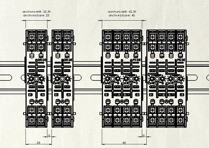
17 INSTALLATION 4.2. Spacing between sockets The following section gives the minimum recommended distances between sockets for the correct installation of ARTECHE relays, both the OP version and the rest, to allow their installation and removal and to prevent unnecessary overheating and damage to the useful life of the relays. The natural position of the relay is considered when the DIN rail is in horizontal position, the socket in vertical position mounted on the rail, and the relay mounted on the socket, with front plate legible facing the user. In case the position of the relay is not the natural one, the used of retaining clips is recommended, in order to avoid that the relay loosens from the socket. With reference to the vertical installation of the relays, in order to avoid overheating, the distances between sockets and relays will be approximately three times the indicated below For OP relays (contactors and impulse relays included): On IP10 front connection sockets and clamp IP20 sockets, the width of the socket is similar to the width of the relays. The sockets include 2,50mm distancing bars located at the lateral side of each socket, which guarantee a minimum distance of 5mm when installing two sockets together. In IP20 front connection sockets and rear connection sockets, the width of the sockets is smaller than the width of the relays. The relays are, in their three sizes D, F and J, 2,50mm wider than their corresponding socket. Therefore, when installing these sockets, it is necessary to take into account not only the minimum distance of 5 mm between the relays, but also the 1,25mm the relay protrudes from the socket on each side. That means the minimum distance between sockets must be 7,50mm. In this case there is no external element which guarantees this distance, so it must be taken into account by the installer Sockets and accessories for auxiliary relays User manual 17
18 INSTALLATION (mm) Relay width Socket width D 22,50 20 F 42,50 40 J 82,50 80 The distances (mm) between sockets for OP relays are: Front connection sockets Rear connection sockets Relay size DE IP10 and DE CL IP20 (guaranteed with distancing bars on the socket) DE IP20 TR D 5 7,50 7,50 F 5 7,50 7,50 J 5 7,50 7, For latching relays (No OP): In latching relays the width of the relays is bigger than the width of the sockets. Therefore the distance between sockets will be calculated taking into account the width difference between relays and sockets. Relay size Width (mm) DE IP10 socket CL IP20 socket DE IP20 socket TR socket F J Socket Relay Socket Relay The minimum distance of 5mm is in this case not necessary, as these relays do not have permanent consumption. Only 1,5mm will be added on each side of the relay to ease plug and unplug. The distances are (mm): Sockets and accessories for auxiliary relays User manual 18
19 INSTALLATION Relay size Front connection sockets Rear connection sockets IP10 IP20 CL IP20 TR F J In case of using spring type retaining clips, to ease plug and unplug of the sockets, the distance (mm) between them will be as follows: Relay size Front connection sockets Rear connection sockets IP10 IP20 CL IP20 TR F J Installation on DIN rail: Summary of the distances (mm) that should be kept: Size DE IP10 and DE CL IP20 sockets (guaranteed with distancing bars on the socket) DE IP20 socket Rear socket OP Latching OP Latching OP Latching D , , F 5 5 (11) 7,50 8 (14) 7,50 8 (14) J 5 10* (15) 7,50 13 (18) 7,50 13 (18) * Not guaranteed with distancing bars. Between brackets the distance when using spring type retaining clip NOTE: In case of using spring type retaining clip (no OP relays), the retaining clip must be mounted on the socket before it is installed. Sockets and accessories for auxiliary relays User manual 19


20 INSTALLATION IP10 and CL IP20 IP20 TR Sockets and accessories for auxiliary relays User manual 20


21 INSTALLATION 4.4. Installation I size relay in a flush mounting socket: Relay positioning Relay connection Sockets and accessories for auxiliary relays User manual 21

 Sockets and accessories")
22 INSTALLATION Cover fixation Cable connections (Information provided printed on each socket) Sockets and accessories for auxiliary relays User manual 22
23 RETAINING CLIPS Chapter 5. Retaining clips The design of the new OP sockets allows both OP relays and the rest (NO OP) to be plugged into them, except for the D size sockets. If retaining clip is needed, their definition will depend on the combination of relay and socket. Type OP Socket OP Relay E0 Universal Universal (RD OP; RF OP; RJ OP; TDF OP; VDF OP; VDJ OP; RJS OP; RUT OP; CD; CF; CJ; RBF) E41 DN DE IP RD OP, CD E40 FN DE IP RF OP, CF E43 FN DE IP TDF OP; VDF OP; RUT OP, RBF E42 FN TR OP RF OP, CF E44 FN TR OP TDF OP; VDF OP; RUT OP; RBF E45 JN DE IP RJ OP, CJ E47 JN DE IP TDJ OP; VDJ OP E46 JN TR OP RJ OP, CJ E48 JN TR OP TDJ OP; VDJ OP Type OP Socket No OP Relay E30 FN DE IP RF (except RF4SY for VCA, RF4R, RFV and RUT) E31 FN DE IP BF; RFV; VDF; TF; TF-FT; RUT; RF-4R, RF-4SY for VAC E20 FN TR OP RF (except RF-4SY for VAC, RF4R, RFV and RUT) E21 FN TR OP BF; RFV; VDF; TF; TF-FT; RUT; RF4R, RF4SY for VAC E28 JN DE IP RJ for VDC (except RJ8R) E29 JN DE IP BJ; UJ; IJ; TJ; RJ for VAC, RJ8R E26 JN TR OP RJ for VDC (except RJ8R) E27 JN TR OP BJ; UJ; IJ; TJ; RJ for VAC, RJ8R Type No OP Socket OP Relay E24 FN DE RF OP, CF E25 FN DE VDF OP; TDF OP; RUT OP, RBF Sockets and accessories for auxiliary relays User manual 23
24 RETAINING CLIPS Type No OP Socket OP Relay E22 F TR RF OP, CF E23 F TR VDF OP; TDF OP; RUT OP, RBF E34 JN-DE RJ OP, CJ E35 JN-DE TDJ OP E32 J-TR RJ OP, CJ E33 J-TR TDJ OP Type No OP Socket No OP Relay E1 E2 E4 E5 FN-DE (front screw connection) FN-DE2C ( front double clip connections) FN-DE (front screw connection) FN-DE2C ( front double clip connections) JN-DE (front screw connection) JN-DE2C ( front double clip connections) JN-DE (front screw connection) JN-DE2C ( front double clip connections) RF (except RF4SY for VAC, RFV and RUT) BF, RFV, VDF, TF, TF-FT, TDF RUT, RF4SY for VAC RJ for VDC (except RJ8R) BJ, UJ, IJ, RJ for VAC, RJ8R E6 DN-DE (front screw connection) RD E7 E8 E10 E11 E12 F-DE (rear screw connection) FN-DE2C ( rear double clip connections) F-TR (rear screw connection) FN-TR2C ( rear double clip connections) J-TR (rear screw connection) J-TRC (rear screw connection) JN-DE2C ( rear double clip connections) J-TR (rear screw connection) J-TRC (rear screw connection) J-TR2C ( rear double clip connections) D-TR (rear screw connection) DN-TRC( rear clip connections) RF except RF4SY for VAC, RJ8R BF, RFV, VDF, TF, TF-FT, TDF RUT, RF4R, RF4SY for VAC RJ for VDC ( except RJ8R) BJ, UJ, IJ, RJ for VAC, RJ8R RD To fit the E0 universal retaining clip: Insert the retaining clips in the housing in the socket as shown in the following figure. Fully fit the retaining clip against the socket on the lower part of the DIN rail with a light vertical pressure. Insert the relay. Sockets and accessories for auxiliary relays User manual 24


25 RETAINING CLIPS Press on the retaining clip in the area marked PUSH at right angles to the relay until it clips onto the cover (a click is heard). To remove the relay, release the retaining clip by pressing lightly on it as shown in the following figure. Sockets and accessories for auxiliary relays User manual 25

 or with No OP")


26 SECURITY PINS Chapter 6. Security pins Security pins may be fitted to the OP sockets to be used with OP relays (instantaneous relays RD, RF and RJ, time-lag relays TDF and TDJ, trip circuit supervision relays VDF and VDJ). These security pins are not suitable to be used with No OP relays (latching relays BF and BJ, supply circuit supervision relays RUT) or with No OP sockets. These security pins are placed in the sockets and in the relays to allow the client/user to code the relays and sockets to avoid errors when replacing relays already installed so that only a correct relay model can be connected (e.g., RF-4 OP00001 for 125 VDC). The sockets have star-shaped sockets as shown in the following figure which allow a large number of combinations bases. Depending on the socket model, they allow a large number of combinations: D sockets 64 combinations (2 pins). F sockets: 4096 combinations (4 pins). J sockets: combinations (8 pins) The sockets also have nerves (shown in red in the figures above and below) that prevent the erroneous fitting of the relay, ensuring that each relay terminal is connected to its proper socket terminal: Sockets and accessories for auxiliary relays User manual 26
27 TESTS Chapter 7. Tests Electrical security test: IEC Dielectric test: 2 KV. 50Hz. 1min Surge withstand: 5 KV., 0,5 J., 1,2/50 s Insulation: 500 VDC. > 100MOhm Mechanical safety tests: Connection capacity and thread maximum torque: IEC Cable extraction force: IEC Environmental tests: Thermal shock: IEC , +70ºC / -25ºC / 5 cycles of 3h+3h Damp heat: IEC , 40ºC / 93%RH / 4 days Sinusoidal vibrations: EN : Fc Shock: EN : Ea, 5Hz - 8 Hz: 3,5mm de amplitude. 8Hz Hz: 1g Bump test: EN : Eb, 15 g / 11 ms Seismic qualification: IEEE , IEEE C , ZPA 5 Free fall test: EN : procedure 1, 1.000mm / 2 falls from each X, Y and Z position Thermal test: Temperature rise at rated voltage: EN , 55ºC / 10A / 3h Functional tests: Resistance of paints to solvents: IEC Engaging and separating forces (basic test procedures and measurement methods): EN Degrees of protection provided by enclosures (IP code): EN Sockets and accessories for auxiliary relays User manual 27

28 Arteche
AUXILIARY RELAYS FOR TRIPPING APPLICATIONS
 AUXILIARY RELAYS FOR TRIPPING APPLICATIONS This document may be subject to changes. Contact ARTECHE to confirm the characteristics and availability of the products described here. Moving together INDEX..............
Thermal-Magnetic Circuit Breaker 2216-S
 Thermal-Magnetic Circuit Breaker 226-S Description One and two pole thermal-magnetic circuit breaker in compact design with slide actuator, trip-free mechanism, various trip characteristics and optional
LATCHING AUXILIARY RELAYS
 LATCHING AUXILIARY RELAYS This document may be subject to changes. Contact ARTECHE to confirm the characteristics and availability of the products described here. Moving together INDEX. 4. 5. 6. 7. 9.
Slim Relay G2RV. Model Number Structure. Ordering Information. Model Number Legend. List of Models. Relay and Socket Combinations
 Slim Relay G2RV The World's First Industrial Slim Relay Large plug-in terminals for reliable connection. LED indicator and mechanical flag to check operation. Transparent housing enables checking relay
Solid-state Timer H3YN
 Solid-state Timer H3YN Miniature Timer with Multiple Time Ranges and Multiple Operating Modes Minimizes stock. Pin configuration compatible with MY Power Relay. Standard multiple operating modes and multiple
SLIMCON-6 24V DC POWERED ISOLATING SIGNAL CONVERTER
 SLIMCON-6 24V DC POWERED ISOLATING SIGNAL CONVERTER Whilst every effort has been taken to ensure the accuracy of this document, we accept no responsibility for damage, injury, loss or expense resulting
VEO. V2PF480Y/277VSY01 Art.Nr.: V2PF480Y/277VSY01P Art.Nr.: TECHNICAL DATA
 Monitoring of phase sequence and phase loss Monitoring of asymmetry Supply voltage 208-480 V AC Supply circuit = measuring circuit 1 change-over contact Width 22,5 mm Control elements Asymmetry Status
VEO. V2ZS V AC/DC Art.Nr.: V2ZS20P V AC/DC Art.Nr.: TECHNICAL DATA
 4 time ranges 4 transition times Supply voltage 12-240V AC/DC 2 normally open contacts Width 22,5 mm Control elements Fine adjustment star contactor Setting of time range star contactor Transit time Status
Classification Enclosure rating Input voltage Type of
 Slim Relay G2RV The World's First Industrial Slim Relay Large plug-in terminals for reliable connection. LED indicator and mechanical flag to check operation. Special input type with gold plated contacts.
Electronic timer CT-ARS.11
 2CDC 251 088 F0t07 Features Rated control supply voltage 24 240 V AC/DC Single function OFF delay timer without auxiliary voltage One device includes 7 time ranges (0.05 s 10 min) 1 c/o (SPDT) contact
E-STOP relay, safety gate monitor
 Safety relay for monitoring E-STOP pushbuttons, safety gates and light barriers. Approvals Unit features Positive-guided relay outputs: 2 safety contacts (N/O), instantaneous 1 semiconductor output Connection
FLEX Ex Spring Clamp Terminal Base
 Installation Instructions FLEX Ex Spring Clamp Terminal Base (Cat. No. 1797-TB3S) 1 10 11 4 Only remove this cover plug if connecting another terminal base unit. 3 5 6 12 2 7 8 9 41253 Component Identification
Electronic timer CT-ERD.12
 2CDC 251 092 F0t06 a Rotary switch for the preselection of the time range b Potentiometer with direct reading scale for the fine adjustment of the time delay c U: green LED V control supply voltage applied
E-STOP relays, safety gate monitors
 Safety relay for monitoring E-STOP pushbuttons, safety gates and light barriers. Approvals Block diagram Unit features Positive-guided relay outputs: 6 safety contacts (N/O), instantaneous 4 auxiliary
Electronic timer CT-ERS.12 ON-delayed with 1 c/o contact Data sheet
 2CDC 251 056 F0t07 Features Rated control supply voltage 24-48 V DC, 24-240 V AC Single-function ON-delay timer One device includes 10 time ranges (0.05 s - 300 h) 1 c/o contact 2 LEDs for status indication
Faults on the system Proximity switch connection technology:
 Speed monitor for connection to a base unit from the PNOZmulti modular safety system Approvals Unit features Monitoring of 2 independent axes Connection of 2 incremental encoders or 4 proximity switches
Positive-guided relay outputs: 3 safety contacts (N/O), instantaneous. 1 auxiliary contact (N/C), instantaneous
, instantaneous. 1 auxiliary contact (N/C), instantaneous") Two-hand control unit for press controllers and safety circuits Approvals Unit features Positive-guided relay outputs: 3 safety contacts (N/O), instantaneous 1 auxiliary contact (N/C), instantaneous 1
Two-hand control unit for press controllers and safety circuits Approvals Unit features Positive-guided relay outputs: 3 safety contacts (N/O), instantaneous 1 auxiliary contact (N/C), instantaneous 1
MMLG 01, 02, 03, 04 MMLB01
 MMLG 01, 02, 03, 04 MMLB01 Technical Data Test Blocks and Test Plugs Publication Reference: MMLG_MMLB/EN/TD/B - ALSTOM 2015. All rights reserved. Information contained in this document is indicative only.
Electronic timer CT-ERS.21
 2CDC 251 057 F0t07 Features Rated control supply voltage 24 240 V AC/DC Single function ON delay timer One device includes 10 time ranges (0.05 s 300 h) 2 c/o contacts 2 LEDs for status indication Width
XB4BK123B5. Product data sheet Characteristics. Complete illuminated selector switch. position stay put 1NO+1NC 24V. Main.
 Characteristics green complete illuminated selector switch Ø22 2- position stay put 1NO+1NC 24V Main Range of product Product or component type Device short name Bezel material Fixing collar material Mounting
Module 18plus. Description. 18plus
 Module 8plus Description Wiring of load and signal lines in a space-saving manner will become ever more important for designers of electrical plants and systems, because all control cabinets and control
Electronic timer CT-AHD.22
 2CDC 251 093 F0t06 a Rotary switch for the preselection of the time range b Potentiometer with direct reading scale for the fine adjustment of the time delay c U: green LED V control supply voltage applied
XB4BW33B5 green flush complete illum pushbutton Ø22 spring return 1NO+1NC 24V
 Characteristics green flush complete illum pushbutton Ø22 spring return 1NO+1NC 24V Product availability : Stock - Normally stocked in distribution facility Price* : 119.00 USD Main Range of product Product
Positive-guided relay outputs: 3 safety contacts (N/O), instantaneous. 1 auxiliary contact (N/C), instantaneous
, instantaneous. 1 auxiliary contact (N/C), instantaneous") Safety relay for monitoring E-STOP pushbuttons. Approvals Unit features Positive-guided relay outputs: 3 safety contacts (N/O), instantaneous 1 auxiliary contact (N/C), instantaneous Safe separation of
Safety relay for monitoring E-STOP pushbuttons. Approvals Unit features Positive-guided relay outputs: 3 safety contacts (N/O), instantaneous 1 auxiliary contact (N/C), instantaneous Safe separation of
XB4BW73731B5 green flush/red projecting illuminated double-headed pushbutton Ø22 1NO+1NC 24V
 Product datasheet Characteristics XB4BW73731B5 green flush/red projecting illuminated double-headed pushbutton Ø22 1NO+1NC 24V Complementary Product weight Resistance to high pressure washer Colour of
Switches and Indicators 84
 Switches and Indicators 84 84 Switches and Indicators Index Series 84 Description Page 177 Product Assembly Page 178 Mounting Instruction Page 179 Product Range - pushbuttons for flush mounting - accessories
Contact expander modules
 Gertebild ][Bildunterschrift Kontakterweiterungen Contact expansion module for increasing the number of available contacts Approvals Zulassungen Unit features Gertemerkmale Positive-guided relay outputs:
XB4BS542 red Ø40 Emergency switching off pushbutton Ø22 latching turn release 1NC
 Characteristics red Ø40 Emergency switching off pushbutton Ø22 latching turn release 1NC Complementary CAD overall width CAD overall height CAD overall depth Terminals description ISO n 1 Product weight
Siemens AG SENTRON 3NJ4, 3NJ5 In-Line Fuse Switch Disconnectors up to 2000 A
 Switch Disconnectors Introduction Overview All key product features at a glance Compliant with IEC/EN 60439-1, IEC/EN 6094-3 Voltage levels up to 690 V AC Rated operational current from 160 A to 2000 A
XB5AS8445 red Ø40 Emergency stop, switching off Ø22 trigger latching turn release 1NO+1NC
 Characteristics red Ø40 Emergency stop, switching off Ø22 trigger latching turn release 1NO+1NC Main Range of product Product or component type Device short name Bezel material Fixing collar material Mounting
Datasheet - SRB 402EM-24V
 Print - Create PDF - Create EXCEL file 20.04.2011-18:31:35h Datasheet - SRB 402EM-24V Output expanders / SRB 402EM Expander module for contact expansion 4 safety contacts, STOP 0 2 Signalling outputs (Minor
Electronic timer CT-ARS.21 OFF-delayed without auxiliary voltage with 2 c/o (SPDT) contacts
 contacts") Data sheet Electronic timer CT-ARS.21 OFF-delayed without auxiliary voltage with 2 c/o (SPDT) contacts The CT-ARS.21 is an electronic timer from the CT-S range with true OFF-delay. It provides 7 time ranges
Data sheet Electronic timer CT-ARS.21 OFF-delayed without auxiliary voltage with 2 c/o (SPDT) contacts The CT-ARS.21 is an electronic timer from the CT-S range with true OFF-delay. It provides 7 time ranges
Control elements. Fine adjustment. Status indication. 24 V DC typ. 0,25 W / 0,25 VA. 24 V DC typ. 0,03 W / 0,09 VA. 0,15 3 s. 0,5 10 h.
 On-Delay 10 time ranges Supply voltage 24-240V AC/DC 1 change-over contact Width 22,5mm Control elements Fine adjustment Setting of time range Status indication LED U/t: Supply voltage LED R: Relay status
Type MVTT 14 and MVTT 15: Static Digital Time delay relays
 Type MVTT 4 and MVTT 5: Static Digital Time delay relays Features 000/ setting range Time settings easily selected by means of thumbwheel switches Provide time delayed pick-up, or drop-off Compact construction
MSR 2400R. Rugged Power System for Military and Heavy Duty Applications
 MSR 2400R Rugged Power System for Military and Heavy Duty Applications 2400 W modular power system Power supply or battery charging systems Parallel n+1 connection, up to 90A Series connection, up to 360VDC
H3CA-8H-AC/100/110/120
 Solid-State Timer 1/16 DIN, Digital-Set Timer with 0.1 Second to 9,990 Hours Range 8 field-selectable operation modes Universal AC/DC supply voltage timers available Operations include ON-delay, Repeat
ST 200 M data sheet System pro M compact miniature circuit breakers for supplementary protection acc. to UL 1077
 MINIATURE CIRCUIT BREAKERS ST 200 M data sheet System pro M compact miniature circuit breakers for supplementary protection acc. to UL 1077 The ST 200 M miniature circuit breaker provides supplementary
VEO. V2ZR V AC/DC Art.Nr.: V2ZR10P V AC/DC Art.Nr.: TECHNICAL DATA
 Off-Delay 10 time ranges Supply voltage 24-240V AC/DC 1 change-over contact Width 22,5 mm Control elements Fine adjustment Setting of time range Status indication LED U/t: Supply voltage LED R: Relay status
RW-E. Overloads. Solid-State Overload Relays. Standard Features
 RW-E The new RW_E Solid State Overload relays are developed with cutting edge technology according to the most demanding standards worldwide. With its wide current/mp setting; the RW_E OL Relay can be
Motor protection relays
 Thermal overload relays for currents between 0.09 and 420A Electronic thermal overload relays for currents between 0.4 and A Electronic thermal overload relays with selectable tripping class: 5--20-30
Solid-state Timer. Ordering Information. Miniature Timer with Multiple Time Ranges and Multiple Operating Modes H3YN- - Accessories (Order Separately)
") Solid-state Timer Miniature Timer with Multiple Time Ranges and Multiple Operating Modes Minimizes stock. Pin configuration compatible with MY Power Relay. Standard multiple operating modes and multiple
Solid-state Timer Miniature Timer with Multiple Time Ranges and Multiple Operating Modes Minimizes stock. Pin configuration compatible with MY Power Relay. Standard multiple operating modes and multiple
Electronic timer CT-ARS.11 OFF-delayed without auxiliary voltage with 1 c/o (SPDT) contact
 contact") Data sheet Electronic timer CT-ARS.11 OFF-delayed without auxiliary voltage with 1 c/o (SPDT) contact The CT-ARS.11 is an electronic timer from the CT-S range with true OFF-delay. It provides 7 time ranges
Data sheet Electronic timer CT-ARS.11 OFF-delayed without auxiliary voltage with 1 c/o (SPDT) contact The CT-ARS.11 is an electronic timer from the CT-S range with true OFF-delay. It provides 7 time ranges
VEO. V2UF230V10 Art.Nr.: TECHNICAL DATA
 Continous voltage monitoring Mains fluctuation detection Detects voltage drop / short interruptions of at least 10ms Prevents undefined states in switching and control systems Generates reset pulse after
VL BPC 100. Valueline configurable box PC. Data sheet 3063_en_E. 1 Description. 2 Features
 Valueline configurable box PC Data sheet 0_en_E Description PHOENIX CONTACT 0-07- Features The VL BPC 000 is a configurable box PC that can be mounted either directly on a wall or on a DIN rail. The VL
XB4BT845 Red Ø40 Emergency stop, switching off Ø22 latching push pull 1NC+1NO
 Characteristics Red Ø40 Emergency stop, switching off Ø22 latching push pull 1NC+1NO Product availability : Stock - Normally stocked in distribution facility Price* : 101.00 USD Main Range of product Product
Magnetic and Hydraulic-Magnetic Circuit Breaker
 Description Single or multipole hydraulic-magnetic circuit breakers with trip-free - mechanism and toggle actuation. A choice of switching characteristics ensures suitability for a wide range of applications.
RE17LAMW on-delay timing relay - 1 s..100 h V AC/ DC - solid state output
 Characteristics on-delay timing relay - 1 s..100 h - 24..240 V AC/ DC - solid state output Main Range of product Product or component type Discrete output type Width Component name Time delay type Time
DSE201, DSE201 M Compact design with enhanced protection
 DSE20, DSE20 M Compact design with enhanced protection Ultimate safety DSE20 and DSE20 M: the highest level of reliability The P+N electronic residual current circuit-breakers with overcurrent protection
Conforms to VDE0435/2021 C/250, VDE0110, VDE0106/P100 Conforms to EN , pren
 Solid-state Power OFF-delay Timer II DIN 22.5-mm Solid-state Power OFF-delay Timer High immunity to invertor noise. Long power OFF-delay times; S-series: up to 12 seconds, L-series: up to 120 seconds.
Analog Voltage Combination Module
 Analog Voltage Combination Module T1F-8AD4DA-2 8-channel analog voltage input 4-channel analog voltage output The combination 8-in and 4-out voltage module uses a T1K-8B or T1K-8B-1 base, which is purchased
XB7EV07BP round pilot light Ø 22 - clear - integral LED - 24 V - screw clamp terminals
 Characteristics round pilot light Ø 22 - clear - integral LED - 24 V - screw clamp terminals Complementary Height Width Depth Terminals description ISO n 1 Product weight Main Range of product Product
XB7NA4234 PB - Spring Rtn, red - 1NC -White "STOP"
 Characteristics PB - Spring Rtn, red - 1NC -White "STOP" Main Range of product Product or component type Device short name Mounting diameter Sep 4, 2018 Harmony XB7 Push-button XB7 Sale per indivisible
E-STOP relays, safety gate monitors
 Safety relay for monitoring E-STOP pushbuttons and safety gates. Approvals Unit features Positive-guided relay outputs: 2 safety contacts (N/O), instantaneous 2 safety contacts (N/O), delay-on de-energisation
RE17LCBM off-delay timing relay - control - 1 s..100 h V - solid state output
 Characteristics off-delay timing relay - control - 1 s..100 h - 24..240 V - solid state output Main Range of product Product or component type Discrete output type Width Component name Time delay type
RUC-M industrial relays for DC loads
 Contact data Number and type of contacts Contact material Rated / max. switching voltage Min. switching voltage Rated load Min. switching current Max. inrush current Rated current Min. breaking capacity
Electronic timer CT-SDS.23 Star-delta change-over with 2 n/o contacts
 Data sheet Electronic timer CT-SDS. Star-delta change-over with n/o contacts The CT-SDS. is an electronic timer from the CT-S range with Star-delta change-over and 7 time ranges. All electronic timers
Installation Guide V290 (Color) This guide provides basic information for Unitronics LCD color touchscreen models V C30B and V T40B.
 This guide provides basic information for Unitronics LCD color touchscreen models V C30B and V T40B.") Vision OPLC Installation Guide V290 (Color) This guide provides basic information for Unitronics LCD color touchscreen models V290-19-C30B and V290-19-T40B. General Description Vision OPLCs are programmable
Vision OPLC Installation Guide V290 (Color) This guide provides basic information for Unitronics LCD color touchscreen models V290-19-C30B and V290-19-T40B. General Description Vision OPLCs are programmable
E-STOP relay, safety gate monitor
 Safety relay for monitoring E-STOP pushbuttons and safety gates. Approvals Unit features Positive-guided relay outputs: 2 safety contacts (N/O), instantaneous 1 semiconductor output Connection options
Positive-guided relay outputs: 4 safety contacts (N/O), instantaneous
, instantaneous") Contact expander module for increasing the number of available contacts Approvals Unit features Positive-guided relay outputs: 4 safety contacts (N/O), instantaneous LED indicator for: Switch status channel
Contact expander module for increasing the number of available contacts Approvals Unit features Positive-guided relay outputs: 4 safety contacts (N/O), instantaneous LED indicator for: Switch status channel
ME PLC Multifunctional housing for complex electronics. Data sheet _en_01. 1 Description
 Multifunctional housing for complex electronics Data sheet 105504_en_01 PHOENIX CONTACT 2013-04-08 1 Description The housings of the ME PLC 40... product group consist of a 40-mm wide housing base with
Product and Applications Description. Application Programs. Example of Operation. Installation Instructions. load circuit AC 230/400V L1 L2 L3 N
 Product and Applications Description Application Programs 20 A4 Binary 906401 4 binary outputs 1 status request available for each output 1 relation can be set allows 1 positive drive for each output initial
ZB4BW061 light block with body/fixing collar for BA9s bulb 250V 1NO
 Characteristics light block with body/fixing collar for BA9s bulb 250V 1NO Product availability : Stock - Normally stocked in distribution facility Price* : 55.00 USD Main Range of product Product or component
Motor protection circuit breakers
 R Motor protection circuit breakers Motor protection circuit breakers are used for start-up and protection of electric motors (industry, small machines, external use, agricultural machines, compressors,
Safe monitoring relays
 monitor for safe standstill monitoring Approvals Block diagram Unit features Positive-guided relay outputs: 2 safety contacts (N/O), instantaneous 1 auxiliary contact (N/C), instantaneous LED indicator
Safe timer relay/contact expansion modules
 Contact expander module for increasing the number of available contacts, Pulse-on timer relay for step-by-step control of movement sequences, Delay-on energisation timer for unlocking an interlock with
ZB4BW353 orange flush illuminated pushbutton head Ø22 spring return for integral LED
 Characteristics orange flush illuminated pushbutton head Ø22 spring return for integral LED Main Range of product Product or component type Device short name Product compatibility Bezel material Head type
3RM1 Hybrid Starters 6SIRIUS. contents. Industrial Controls Product Catalog 2017
 3RM1 Hybrid Starters Industrial Controls Product Catalog 2017 Section contents 3RM1 Compact - Hybrid Starters Overview /2 General Data /3 Selection and ordering data /4 Accessories /5 - /9 Technical Data
Output Voltage* (nom.)(adjustable)
(adjustable)") Industrial Power Supplies TBLC Series, 6 90 W Low profile case, module depth only 55 mm Suitable for mounting in domestic installation panels Very high efficiency and low standby power -> compliance to
Industrial Power Supplies TBLC Series, 6 90 W Low profile case, module depth only 55 mm Suitable for mounting in domestic installation panels Very high efficiency and low standby power -> compliance to
Model Number Structure
 Solid State Relays CSM DS_E_3_1 Compact, Low-cost, SSR Switching 5 to 20 A Wide load voltage range: 75 to 264 VAC. Both 100-V and 200-V loads can be handled with the same model. Dedicated, compact aluminum
ict contactors EN 61095, IEC 1095 Interference
 ict contactors DB23399 DB669 DB06604 Country approval pictograms EN 6095, IEC 095 ict contactors are available in two versions: b Contactors without manually-operated b Contactors with manually-operated.
Solid-state Timer. Ordering Information. Specifications. Miniature Timer Compatible with the MY Relay. Accessories. Time Ranges
 Solid-state Timer Miniature Timer Compatible with the MY Relay Large transparent time-setting knob facilitates time setting. Flat-blade and Phillips screwdrivers can also be used for time setting. Approved
MMLB 01/MMLB 02 Multi-finger Test Plug/ Single-finger Test Plug Technical Data MMLB_EN_TD_A
 AUTOMATION MMLB 01/MMLB 02 Multi-finger Test Plug/ Single-finger Test Plug Technical Data MMLB_EN_TD_A GRID Note: The technical manual for this device gives instructions for its installation, commissioning,
VZBs. Power PCB Relay RT2 2 pole 8 A, DC and AC-coil. Features. Contact data
 Features 2 C/O or 2 N/O contacts Sensitive coil 400 mw DC- or AC-coil 5 kv / 10 mm coil-contact Protection class II (VDE 0700) Height 15.7 mm Sockets with PCB-type or screw-type terminals Applications
PRODUCT SPECIFICATION. PC Board Relays. Series.
 PRODUCT SPECIFICATION PC Board Relays 26 Series www.wernerelektrik.com Technical Data... Specifications...2 Model Number Structure - Relays...3 Model Number Selection...4 Dimensions... 5-6 Accessories...7
H3CR-F H3CR-F8 H3CR-F-300 H3CR-F8-300
 R Solid-State Repeat-Cycle Timer 1/1 DIN Solid-State Repeat-Cycle Timer Wide power supply ranges of 100 to 240 VAC 24 VAC/VDC, 12VDC Combinations of independent long or short / time settings are possible
Positive-guided relay outputs: 4 safety contacts (N/O), instantaneous
, instantaneous") ohne Abbildung Contact expansion module for increasing the number of available contacts Approvals PZE X4.1P with universal power supply Unit features Positive-guided relay outputs: 4 safety contacts (N/O),
ohne Abbildung Contact expansion module for increasing the number of available contacts Approvals PZE X4.1P with universal power supply Unit features Positive-guided relay outputs: 4 safety contacts (N/O),
EMS CX 3 - State and control module for Latching relays and Contactors
 LEGRAND - BP30076 87045 LIMOGES CEDEX FRANCE Telephone: 05 55 06 87 87 Fax: 05 55 06 88 88 Contents Pages 1. Description - Use... 1 2. Range... 1 3. Overall dimensions... 1 4. Preparation - Connection...
E-STOP relays, safety gate monitors
 E-STOP relays, safety gate monitors Up to Category 2, EN 954-1 Unit features Positive-guided relay outputs: 2 safety contacts (N/O), instantaneous Connection options for: E-STOP pushbutton Reset button
XB7NS8442 Emergency stop Ø 22 - red - mushroom head Ø 40 mm - turn to release - 1 NC
 Characteristics Emergency stop Ø 22 - red - mushroom head Ø 40 mm - turn to release - 1 NC Main Range of product Product or component type Device short name Mounting diameter Sep 4, 2018 Harmony XB7 Emergency
This Datasheet for the IC670GBI002 24VDC BUS INTERFACE UNIT.
 This Datasheet for the IC670GBI002 24VDC BUS INTERFACE UNIT http://www.qualitrol.com/shop/p-14508-ic670gbi002.aspx Provides the wiring diagrams and installation guidelines for this GE Field Control module.
XB4BW73731B5 green flush/red projecting illuminated doubleheaded pushbutton Ø22 1NO+1NC 24V
 Product data sheet Characteristics XB4BW73731B5 green flush/red projecting illuminated doubleheaded pushbutton Ø22 1NO+1NC 24V Product availability : Stock - Normally stocked in distribution facility Price*
IDE Load break switches for machine control Remotely trippable switch from 32 to 160 A
 The solution for Load break switches > Industry. > Non critical buildings. > Public Access Sites. > High Rise Buildings. ide_021_a_1_cat ide_022_a_1_cat IDE 4x40 A External operation IDE 4x40 A Direct
PRODUCT SPECIFICATION
 1.0 SCOPE DDR4 DIMM SOCKET This Product Specification covers the 0.85mm centerline gold plated DDR4 DIMM edge card connector for 1.40 ± 0.10 thick memory modules..0 PRODUCT DESCRIPTION.1 PRODUCT NAME AND
INSTRUCTION SHEET. Eaton Logic Controller ELCB Controllers
 2010-12-10 5011699201-PBB1 Eaton Logic Controller ELCB Controllers INSTRUCTION SHEET [Applicable Controllers] ELCB-PB10 ELCB-PB14 ELCB-PB20 ELCB-PB30 ELCB-PB40 IL05001005E 002-1310020-02 Thank you for
RE22R2QGMR Star-Delta Timing Relay s 300h V AC/DC - 2C/O
 Characteristics Star-Delta Timing Relay - 0.05s 300h - 24 240V AC/DC - 2C/O Main Range of product Product or component type Discrete output type Device short name Nominal output current Complementary Contacts
E-STOP relays, safety gate monitors
 Unit features Positive-guided relay outputs: 2 safety contacts (N/O), instantaneous Connection options for: E-STOP pushbutton Reset button LED indicator for: Switch status channel 1/2 Supply voltage See
60W Power over Ethernet Waterproof Adapter PoE IEEE BT Single Port Injector for Outdoor Application
 WWW.PHIHONG.COM 60W Power over Ethernet Waterproof Adapter PoE IEEE BT Single Port Injector for Outdoor Application Features Compliant with the IEEE802.3bt Standard Non-Vented Case with Mounting Bracket
Solid-state Timer. Ordering Information. Ultra-slim Timer for G2R Relay Socket. H3RN-jj. Accessories (Order Separately) Connecting Socket
 Connecting Socket") Solid-state Timer Ultra-slim Timer for G2R Relay Socket Pin configuration compatible with G2R Relay and mounts to the P2R/P2RF Socket. Standard multiple time ranges and multiple operating modes. Conforms
Solid-state Timer Ultra-slim Timer for G2R Relay Socket Pin configuration compatible with G2R Relay and mounts to the P2R/P2RF Socket. Standard multiple time ranges and multiple operating modes. Conforms
RE17LAMW on-delay timing relay - 1 s..100 h V AC/DC - solid state output
 Characteristics on-delay timing relay - 1 s..100 h - 24..240 V AC/DC - solid state output Complementary Control type Voltage range Main Range of product Product or component type Discrete output type Width
E-STOP relays, safety gate monitors
 Unit features Safety gates Gertebild ][Bildunterschrift_NOT_Sch.tuer_Licht Safety relay for monitoring E-STOP pushbuttons, safety gates and light beam devices Approvals Gertemerkmale Positive-guided relay
Description of parts Panel mounting Insert mounting without/with Carrier element Plastic housings
 - Contents Page Features -... 11.02 Component range -... 11.03 Description of parts... 11.04 Latching parts without/with Strain relief and Panel mounting parts... 11.06 Panel mounting... 11.08 Insert mounting
Plug-in unit extension block One sensor extension block allows four plug-in units to be added. Power cable for sensors. Snap-connector inputs
 1 Sensor Block for SC Quick connection of 16 sensors Set of 16 inputs directly hooked up to PLC Up to 16 sensors can be connected on one main block followed by three extension blocks (or one snapconnector
Two-hand control unit
 Unit features Safety features Gertebild ][Bildunterschrift_Zweihand Two-hand control unit for press controllers and safety circuits Approvals Gertemerkmale Positive-guided relay outputs: 3 safety contacts
Introduction Circuit Protection
 Introduction Circuit Protection Weidmuller s DIN-rail mounted circuit breakers are available for use in applications where circuit protection must be able to distinguish between circuit overloads and short
Safety relays PNOZsigma
 Safety relays PNOZsigma Configuration guide, safety relays PNOZsigma Technical catalogue 3.2 November 2008 edition Why does Pilz offer more? Because the integrality of our business activities is what sets
Rhino Redundancy Module PSM24-REM360S. Operating Instructions
 Rhino Redundancy Module PSM4-REM360S Operating Instructions RHINO REDUNDANCY MODULE PSM4-REM360S Description With this module and two power supplies of the PSM series (78, 90, 56, 80 and 360 watt models),
RUC industrial relays of small dimensions
 RUC industrial relays of small dimensions 135 with adaptor (V) Contact data Number and type of contacts Contact material Rated / max. switching voltage Min. switching voltage Rated load Min. switching
XB4BL Main. Device short name. Fixing collar material. Shape of signaling unit head. Contacts type and composition
 Product datasheet Characteristics XB4BL73415 Complementary Product weight Resistance to high pressure washer Colour of marking Operator profile Contacts usage Positive opening Operating travel Operating
TF501, TF521 Terminal Bases
 Ordering Data DATA SHEET TF501, TF521 Terminal Bases 1 Ordering Data Part No. Scope of delivery Product life cycle status 1SAP 117 000 R0271 1SAP 317 000 R0271 1SAP 117 200 R0271 1SAP 317 200 R0271 TF501-CMS,
RM84 miniature relays
 RM84 miniature relays RM84 Contact data Number and type of contacts Contact material Rated / max. switching voltage Min. switching voltage Rated load (capacity) AC AC1 AC15 DC1 DC13 Motor load acc. to