TA0136 USER MANUAL ARDUINO 2 WHEEL DRIVE ULTRASONIC ROBOT KIT
|
|
|
- Cassandra Cook
- 6 years ago
- Views:
Transcription

1 TA0136 USER MANUAL ARDUINO 2 WHEEL DRIVE ULTRASONIC ROBOT KIT I
2 Contents Overview TA Getting started: the 2 Wheel Drive Ultrasonic Robot Kit using Arduino UNO What is Arduino? What is IDUINO UNO?... 1 Software installation Arduino Software/IDE Play with your first Hello World LED example Run your Arduino 2 Wheel Drive code Unboxing and Component list Chassis Frame Installation Arduino Installation Sensor installation Switch Wire Connection Have fun Appendix II

3 Chapter 1 Overview TA0136 Overview TA0136 In this instruction, we will introduce you through the fun project of the Arduino 2 Wheel Drive Ultrasonic Robot Kit. Get your Arduino board kit. Let s get started! Getting started: the 2 Wheel Drive Ultrasonic Robot Kit using Arduino UNO 2.1. What is Arduino? Arduino is an open-source electronics platform based on easy-to-use hardware and software. Arduino boards can read inputs - light on a sensor, a finger on a button, or a Twitter message - and turn it into an output - activating a motor, turning on an LED, publishing something online. You can tell your board what to do by sending a set of instructions to the microcontroller on the board. To do so you use the Arduino programming language (based on Wiring), and the Arduino Software (IDE), based on Processing What is IDUINO UNO? The Iduino Uno is on the ATmega328. It has 14 digital input/output pins (of which 6 can be used as PWM outputs), 6 analogue inputs, a 16 MHz ceramic resonator, a USB connection, a power jack, an ICSP header, and a reset button. It contains everything needed to support the microcontroller; simply connect it to a computer with a USB cable or power it with a AC-to-DC adapter or battery to get started. 1
. Easy!")
4 Chapter 3 Software installation Software installation In this section, we will introduce you the development platform where you translate creative mind into codes and let it fly Arduino Software/IDE Download from here. Open Windows-based app by double clicking it and follow the instruction to complete(remember to install everything driver for Arduino). Easy! Connecting your UNO board with your computer Figure 1 Installation of drivers Connecting UNO and your PC by a blue USB cable, and if connected correctly you will see the green power LED light up and another orange LED is blinking. Find your Serial COM number and note it down. Figure 2 Check Your special COM and note it down the number We need to figure out which channel COM is currently communicating between PC and UNO. Following the path: Control panel Hardware and Sound Devices and Printers Device Manager Ports (COM & LPT) Arduino UNO (COMx) 2


5 Chapter 3 Software installation Note down the COM number as we require this later. As the COM port may vary from time to time, this step is vital. In this case for demonstration purpose, we are using the COM Play with your first Hello World LED example Firstly, let s tell IDE where to find our Arduino port and which board you are currently using: The following instruction (Figure 3 and 4) shows the details: Configuration of Ports Configuration of the Board 3

6 Chapter 3 Software installation It s time to play with you first simple example. Following the path by File Examples 01. Basics Blink. A new code window would pop up, press the arrow symbol to upload. You will notice the orange LED is blinking almost every second Run your Arduino 2 Wheel Drive code Upload to UNO Done uploading! 4

 5. L298N Motor Driver Board 6.")

7 4.1. Unboxing and Component list 1. Acrylic Chassis 2. DC Motors 3. SG90 Servo with horns and Brackets 4. Rubber Wheels 5. Metal Pivot wheel 1. Ultrasonic Sensor 2. Arduino UNO Development Board 3. Arduino Sensor shield V x AA Battery Box (Batteries not included) 5. L298N Motor Driver Board 6. Rocker Switch (Optional configuration please see Chapter 4.4) 7. Jumper Cable with 12 wires Fastener package: 1. 4 x M3 30mm Screws 2. 4 x M3 10mm Screws 3. 4 x M3 8mm Screws 4. 8 x M3 6mm Screws 5. 4 x M3 35mm Spacers 6. 4 x M3 10mm Spacers 7. Self-tapping Screws 8. 8 x Nuts 5

8 4.2. Chassis Frame Installation Remove the protective cover and prepare the items: 1. 4 x M3 6mm Screws 2. 4 x M3 10mm Spacers 3. 4 x M3 6mm screws 4. Metal Pivot Wheel Assemble the M3*10 spacers and M3*6 screws onto the Metal Pivot Wheel 6


9 Screw in the metal pivot wheel to the chassis Gather 4 x M3 10mm screws and nuts to secure L289N Motor Drive board Screw the L289N Motor Drive board from the bottom chassis 7


10 Gather 4 x M3 8mm screws and 4 x M3 35mm spacers Secure Spacers onto the chassis as per the picture on the left. Spacers/Stand-offs should look like this 8


11 Gather the following components: 1. 2 x Acrylic Motor Brackets 2. 4 x M3 35mm Screws 3. 2 x Nuts *Attaching wheel encoders are optional. These are not required for this particular project 9


12 Place acrylic DC motor Brackets on both side of the motors as shown on the left Gather another two acrylic fasteners and two wheels Insert the acrylic fasteners first in pre-cut slot 10


13 Then tighten and secure the DC motor with one nut on the other side Fix the other motor as well Pull the wire through as we need to connect them to the L289N board 11


14 4.3. Arduino Installation Let s fix the Arduino UNO and Sensor shield in the following steps. Prepare the jumper cables Separate the jumper cable set into four and eight configurations Connect the 8 jumpers with L289N board as shown. Please Note: The 8 Jumper cables will eventually attach to the Sensor Expansion Board from the L289N board a few steps from now. Please leave the opposite side free for the following steps. 12


15 Prepare the following: Battery pack: Arduino UNO development board Top acrylic chassis 6 x nuts 6 x M3 10mm screws Peel the protective cover Place the battery pack and UNO board on the top acrylic chassis 13


16 Secure the screws from the bottom It should look like this Feed the jumper wire from the L289N board and pull through to the top acrylic chassis hole to connect with the UNO board later 14


17 Mount the top acrylic chassis to the bottom chassis Use four M3*6 screws to secure top acrylic chassis. It should look like this 15

18 Place the sensor shield on the top of the UNO board and ensure the pins line up with the Uno Board. 16


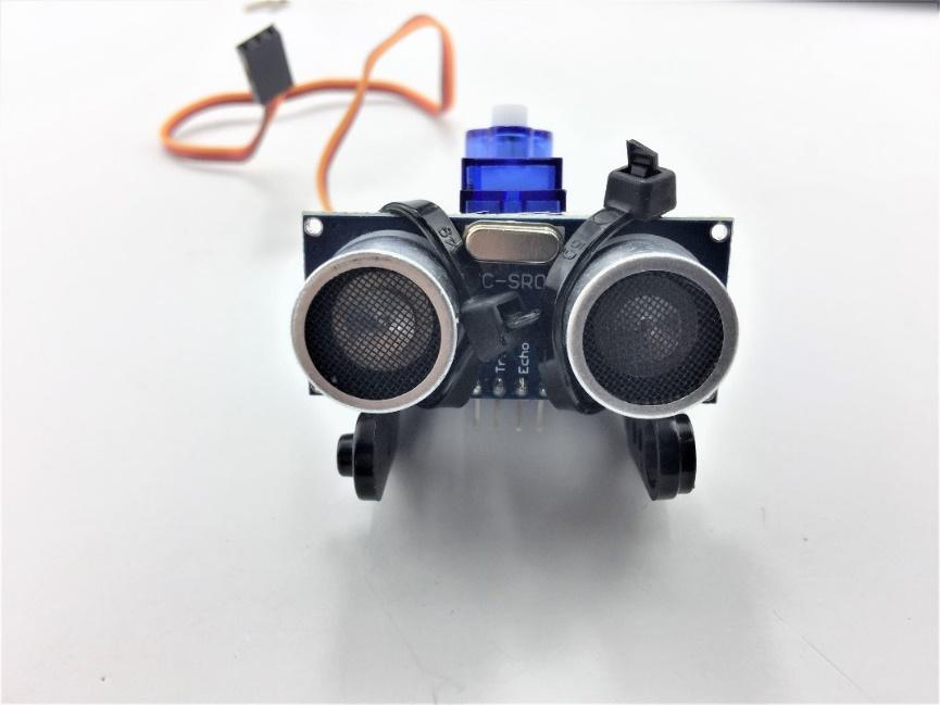
19 4.4. Sensor installation Ultrasonic sensor acts as the eye of this 2-wheel drive car. In the following steps, we are going to guide you through the installation of ultrasonic sensor and servo. Items required in this step Assemble the FPV holder and servo Use two self-tapping screws (in the FPV package) to tighten 17


20 Prepare the items To fit the servo horn into the black holder we need to modify as pictured. Best tool to do this with is a side cutter Caution: Be carefully with cutter and sharp edges of the horn 18


21 Place the modified servo horn inside the bracket and secure with 6 * M2.5 screws in the servo package It should look like this To tighten the ultrasonic sensor, we can use several cable ties (Not included in the Kit). Alternatively, you can use other methods: - Use rubber bands - Thread or Plastic Strings 19

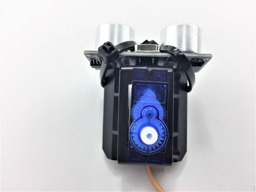
22 It should look like this 20


23 Prepare the Self-tapping screw in the Servo package and tighten the sensor part with servo rack It should look like this Gather four M2.5 screws and corresponding nuts in the FPV package to secure to the bottom chassis 21


24 Finished! 4.5. Switch The switch can save you a lot energy turning the car on and off. However, it s just an option. It can be done by putting the switch in line with the battery box power wire. Insert the switch in pre-cut slot Solder the switch in line with the power cable 22
25 The following diagram shows the switch connection with battery pack and L289N. Caution: Do not modify your programming code when USB cable plugged in Arduino UNO development board and your computer with wires connecting to L289N Motor Drive board as a large amount of current will drain from the USB cable which will burn out the computer USB port. 1 1b 1 GND VMS L289N 0 1a Battery Pack 23
26 4.6. Wire Connection You are almost there. Final step is to wire the cables to power supply (i.e. Battery Box), UNO board, ultrasonic sensor and Servo. The following diagram shows the connection map. Don t panic if this is your first project, you can also follow the connection table 2. Take your time and be patient with wires. Caution: Any incorrect wire connection will lead to problems including device malfunction, device failure, damage to the device or damage to other property. Table 1 Connection table UNO board Sensor Shield L289N GND VMS +(Left) -(Left) +(Right) -(Right) ENA V 6 IN1 9 IN2 10 IN3 11 IN4 Battery Box GND VMS Motor left +(red) -(black) Motor Right +(red) -(black) Servo Ultrasonic sensor V ENB G GND V 5V+ 5 S V + G - V + A1 Trig A0 Echo G - Figure 3 Connection map 24


27 Figure 4 Arduino Sensor shield v5.0 Diagram Figure 5 Overview 25
28 Chapter 5 Have fun Have fun Now it s time to have fun! Turn the power on, and see how your DIY Arduino Robot car goes! After final assembly and activation, the Robot car may require adjustments and debugging. The Robot will perform on how it is programmed. Figuring out what the code is doing is part of the learning process. Reopen your Arduino IDE and we assure you will learn a lot once you gain a deep understanding of the code. This kit is just a starting point and can be expanded to incorporate other sensors and modules. You are limited by your imagination. We are also offering other Arduino Robot Kit versions where you can learn WIFI, Bluetooth, infrared remote control and so many more. Arduino 4 Wheel Drive with Ultrasonic & Line Tracer Bluetooth Robot Kit ( Arduino 4 Wheel Drive with Ultrasonic & Line Tracer Robot Kit ( Arduino 2 Wheel Drive Wireless Bluetooth Robot Kit ( Arduino Robot Arm 4dof Mechanical Claw Kit ( Check our website at Here. ( 26
29 Appendix Appendix Code: ********Code begin******** #include <Servo.h> int pinlb=6; // define pin6 as left back connect with IN1 int pinlf=9; // define pin9 as left forward connect with IN2 int pinrb=10; // define pin10 as right back connect with IN3 int pinrf=11; // define pin11 as right back connect with IN4 int inputpin = A0; // define ultrasonic receive pin (Echo) int outputpin =A1; // define ultrasonic send pin(trig) int Fspeedd = 0; // forward distance int Rspeedd = 0; // right distance int Lspeedd = 0; // left distance int directionn = 0; // Servo myservo; // new myservo int delay_time = 250; // set stable time int Fgo = 8; int Rgo = 6; int Lgo = 4; int Bgo = 2; // forward // turn right // turn left // back void setup() Serial.begin(9600); pinmode(pinlb,output); pinmode(pinlf,output); pinmode(pinrb,output); pinmode(pinrf,output); pinmode(inputpin, INPUT); pinmode(outputpin, OUTPUT); myservo.attach(5); // define the servo pin(pwm) void advance(int a) // forward digitalwrite(pinrb,low); digitalwrite(pinrf,high); digitalwrite(pinlb,low); digitalwrite(pinlf,high); delay(a * 40); void turnr(int d) //turn right digitalwrite(pinrb,low); digitalwrite(pinrf,high); digitalwrite(pinlb,high); digitalwrite(pinlf,low); delay(d * 50); void turnl(int e) //turn left 27
30 Appendix digitalwrite(pinrb,high); digitalwrite(pinrf,low); digitalwrite(pinlb,low); digitalwrite(pinlf,high); delay(e * 50); void stopp(int f) //stop digitalwrite(pinrb,high); digitalwrite(pinrf,high); digitalwrite(pinlb,high); digitalwrite(pinlf,high); delay(f * 100); void back(int g) //back digitalwrite(pinrb,high); digitalwrite(pinrf,low); digitalwrite(pinlb,high); digitalwrite(pinlf,low); delay(g * 300); void detection() //test the distance of different direction int delay_time = 250; // ask_pin_f(); // read forward distance if(fspeedd < 10) // if distance less then 10 stopp(1); back(2); if(fspeedd < 25) // if distance less then 10 stopp(1); ask_pin_l(); delay(delay_time); ask_pin_r(); delay(delay_time); if(lspeedd > Rspeedd) //if left distance more than right distance directionn = Rgo; if(lspeedd <= Rspeedd)//if left distance not more than right //distance directionn = Lgo; //if left if (Lspeedd < 10 && Rspeedd < 10) distance and right //distance both less than 10 directionn = Bgo; else directionn = Fgo; // forward go 28
31 Appendix void ask_pin_f() // test forward distance myservo.write(90); digitalwrite(outputpin, LOW); delaymicroseconds(2); digitalwrite(outputpin, HIGH); delaymicroseconds(10); digitalwrite(outputpin, LOW); float Fdistance = pulsein(inputpin, HIGH); Fdistance= Fdistance/5.8/10; Serial.print("F distance:"); Serial.println(Fdistance); Fspeedd = Fdistance; void ask_pin_l() // test left distance myservo.write(5); delay(delay_time); digitalwrite(outputpin, LOW); delaymicroseconds(2); digitalwrite(outputpin, HIGH); delaymicroseconds(10); digitalwrite(outputpin, LOW); float Ldistance = pulsein(inputpin, HIGH); Ldistance= Ldistance/5.8/10; Serial.print("L distance:"); Serial.println(Ldistance); Lspeedd = Ldistance; void ask_pin_r() // test right distance myservo.write(177); delay(delay_time); digitalwrite(outputpin, LOW); delaymicroseconds(2); digitalwrite(outputpin, HIGH); delaymicroseconds(10); digitalwrite(outputpin, LOW); float Rdistance = pulsein(inputpin, HIGH); Rdistance= Rdistance/5.8/10; Serial.print("R distance:"); Serial.println(Rdistance); Rspeedd = Rdistance; void loop() myservo.write(90); detection(); if(directionn == 2) back(8); turnl(2); Serial.print(" Reverse "); 29
32 Appendix if(directionn == 6) back(1); turnr(6); Serial.print(" Right "); if(directionn == 4) back(1); turnl(6); Serial.print(" Left "); if(directionn == 8) advance(1); Serial.print(" Advance "); Serial.print(" "); ********Code End******** 30
TA0139 USER MANUAL ARDUINO 2 WHEEL DRIVE WIRELESS BLUETOOTH ROBOT KIT
 TA0139 USER MANUAL ARDUINO 2 WHEEL DRIVE WIRELESS BLUETOOTH ROBOT KIT I Contents Overview TA0139... 1 Getting started: Arduino 2 Wheel Drive Wireless Bluetooth Robot Kit using Arduino UNO... 1 2.1. What
TA0297 WEMOS D1 R2 WIFI ARDUINO DEVELOPMENT BOARD ESP8266
 TA0297 WEMOS D1 R2 WIFI ARDUINO DEVELOPMENT BOARD ESP8266 Contents 1. Overview TA0297... 3 2. Getting started:... 3 2.1. What is WeMos D1 R2 Wifi Arduino Development Board?... 3 2.2. What is IDUINO UNO?...
IDUINO for maker s life. User Manual. For IDUINO Mega2560 Board(ST1026)
") User Manual For IDUINO Mega2560 Board(ST1026) 1.Overview 1.1 what is Arduino? Arduino is an open-source prototyping platform based on easy-to-use hardware and software. Arduino boards are able to read
User Manual For IDUINO Mega2560 Board(ST1026) 1.Overview 1.1 what is Arduino? Arduino is an open-source prototyping platform based on easy-to-use hardware and software. Arduino boards are able to read
IDUINO for maker s life. User Manual. For IDUINO development Board.
 User Manual For IDUINO development Board 1.Overview 1.1 what is Arduino? Arduino is an open-source prototyping platform based on easy-to-use hardware and software. Arduino boards are able to read inputs
Arduino Smart Robot Car Kit User Guide
 User Guide V1.0 04.2017 UCTRONIC Table of Contents 1. Introduction...3 2. Assembly...4 2.1 Arduino Uno R3...4 2.2 HC-SR04 Ultrasonic Sensor Module with Bracket / Holder...5 2.3 L293D Motor Drive Expansion
AlphaBot2 robot building kit for Arduino
 AlphaBot2 robot building kit for Arduino SKU 110060864 Description This AlphaBot2 robot kit is designed to use with an Arduino compatible board UNO PLUS. It features rich common robot functions including
1. Introduction Packing list Parts Introduction Uno R3 Board for Arduino Specifications... 6
 Table of Contents Smart Bluetooth Robot Car Kit for Arduino 1. Introduction...4 1.1 Packing list...5 2. Parts Introduction...6 2.1 Uno R3 Board for Arduino...6 2.1.1 Specifications... 6 2.2 HC-SR04 Ultrasonic
StenBOT Robot Kit. Stensat Group LLC, Copyright 2018
 StenBOT Robot Kit 1 Stensat Group LLC, Copyright 2018 Legal Stuff Stensat Group LLC assumes no responsibility and/or liability for the use of the kit and documentation. There is a 90 day warranty for the
Arduino Smart Bluetooth Robot Car Kit User Guide
 Arduino Smart Bluetooth Robot Car Kit User Guide UCTRONICS Table of Contents 1. Introduction... 4 1.1 Packing list... 5 2. Assembly... 6 2.1 Arduino Uno R3... 6 2.1.1 Specifications... 6 2.2 HC-SR04 Ultrasonic
HUB-ee BMD-S Arduino Proto Shield V1.0
 HUB-ee BMD-S Arduino Proto Shield V1.0 User guide and assembly instructions Document Version 1.0 Introduction 2 Schematic 3 Quick user guide 4 Assembly 5 1) DIP Switches 5 2) Micro-MaTch Connector Headers
GUIDE TO SP STARTER SHIELD (V3.0)
") OVERVIEW: The SP Starter shield provides a complete learning platform for beginners and newbies. The board is equipped with loads of sensors and components like relays, user button, LED, IR Remote and
OVERVIEW: The SP Starter shield provides a complete learning platform for beginners and newbies. The board is equipped with loads of sensors and components like relays, user button, LED, IR Remote and
Instruction Manual. Model RBA18
 Instruction Manual Model RBA18 The Robo-Arm Kit for Arduino is designed to teach the following: 1. How to build a mechanical arm, piece-by-piece. 2. Basic workings of mechanical arm 3. Coding and control
Arduino 101 AN INTRODUCTION TO ARDUINO BY WOMEN IN ENGINEERING FT T I NA A ND AW E S O ME ME NTO R S
 Arduino 101 AN INTRODUCTION TO ARDUINO BY WOMEN IN ENGINEERING FT T I NA A ND AW E S O ME ME NTO R S Overview Motivation Circuit Design and Arduino Architecture Projects Blink the LED Switch Night Lamp
USER MANUAL ARDUINO I/O EXPANSION SHIELD
 USER MANUAL ARDUINO I/O EXPANSION SHIELD Description: Sometimes Arduino Uno users run short of pins because there s a lot of projects that requires more than 20 signal pins. The only option they are left
Make your own secret locking mechanism to keep unwanted guests out of your space!
 KNOCK LOCK Make your own secret locking mechanism to keep unwanted guests out of your space! Discover : input with a piezo, writing your own functions Time : 1 hour Level : Builds on projects : 1,,3,4,5
Model: K0073. Smart Robot Car Kit Quick Start Guide
 Model: K0073 Smart Robot Car Kit Quick Start Guide Smart Robot Car Kit Smart Robot Car Kit M2 nuts 4 pieces M24 micro servo screws 2 bars PTZ self-tapping screws 4 bars M210 round head screws 4 bars 15
GRBL SHIELD FOR ARDUINO UNO USER MANUAL
 GRBL SHIELD FOR ARDUINO UNO USER MANUAL YRCNC 2017 Introduction Thanks for supporting us! Hope you will have many hours of fun using this shield and that plenty hours of issueless cutting! The main features
ROBOTLINKING THE POWER SUPPLY LEARNING KIT TUTORIAL
 ROBOTLINKING THE POWER SUPPLY LEARNING KIT TUTORIAL 1 Preface About RobotLinking RobotLinking is a technology company focused on 3D Printer, Raspberry Pi and Arduino open source community development.
AndyMark Arduino Tutorial
 AndyMark Arduino Tutorial Tank Drive June 2014 Required: Required Software List: - Kit Arduino IDE - Robot Power Cable Kit (am-0975) RobotOpen Arduino Shield Software - Battery Base Package (am-0477) RobotOpen
keyestudio Keyestudio MEGA 2560 R3 Board
 Keyestudio MEGA 2560 R3 Board Introduction: Keyestudio Mega 2560 R3 is a microcontroller board based on the ATMEGA2560-16AU, fully compatible with ARDUINO MEGA 2560 REV3. It has 54 digital input/output
DIY Remote Control Robot Kit (Support Android) SKU:COMB0004
 SKU:COMB0004") DIY Remote Control Robot Kit (Support Android) SKU:COMB0004 Contents [hide] 1 Overall o 1.1 Microcontroller 2 Part List o 2.1 Basic Kit o 2.2 Upgrade Components o 2.3 Additional Parts Required 3 Assembly
DIY Remote Control Robot Kit (Support Android) SKU:COMB0004 Contents [hide] 1 Overall o 1.1 Microcontroller 2 Part List o 2.1 Basic Kit o 2.2 Upgrade Components o 2.3 Additional Parts Required 3 Assembly
HUB-ee BMD-S Arduino Proto Shield V1.1
 HUB-ee BMD-S Arduino Proto Shield V1.1 User guide and assembly instructions Document Version 0.5 Introduction & Board Guide 2 Schematic 3 Quick User Guide 4 Assembly Guide 6 Kit Contents 7 1) Diodes and
Android Spybot. ECE Capstone Project
 Android Spybot ECE Capstone Project Erik Bruckner - bajisci@eden.rutgers.edu Jason Kelch - jkelch@eden.rutgers.edu Sam Chang - schang2@eden.rutgers.edu 5/6/2014 1 Table of Contents Introduction...3 Objective...3
Web Site: Forums: forums.parallax.com Sales: Technical:
 Web Site: www.parallax.com Forums: forums.parallax.com Sales: sales@parallax.com Technical: support@parallax.com Office: (916) 624-8333 Fax: (916) 624-8003 Sales: (888) 512-1024 Tech Support: (888) 997-8267
Arduino Robots Robot Kit Parts List
 Arduino Robots Robot Kit Parts List (1) Metal Chassis (2) Push Button Activators (2) Servo Motors w/ Cross Wheels (2) IR Receivers (1) Control Board (1) Piezo Speaker (1) Dual-Sided Screwdriver (1) Cotter
DIY Line Tracking Smart Car with AT89C2051
 DIY Line Tracking Smart Car with AT89C2051 1. Introduction: A DIY Smart Car design involves mechanical structure, electronic based sensor principle, automatic control, and even knowledge of microcontroller
Arduino Programming and Interfacing
 Arduino Programming and Interfacing Stensat Group LLC, Copyright 2017 1 Robotic Arm Experimenters Kit 2 Legal Stuff Stensat Group LLC assumes no responsibility and/or liability for the use of the kit and
ARDUINO UNO R3 BASED 20A ROBOT CONTROL BOARD [RKI-1580] Page 1
![ARDUINO UNO R3 BASED 20A ROBOT CONTROL BOARD [RKI-1580] Page 1](/thumbs/73/69461282.jpg "ARDUINO UNO R3 BASED 20A ROBOT CONTROL BOARD [RKI-1580] Page 1") ARDUINO UNO R3 BASED 20A ROBOT CONTROL BOARD [RKI-1580] http://www.robokitsworld.com Page 1 1. Introduction: The Arduino UNO R3 based 20A robot control board is a versatile motor controller for driving
ARDUINO UNO R3 BASED 20A ROBOT CONTROL BOARD [RKI-1580] http://www.robokitsworld.com Page 1 1. Introduction: The Arduino UNO R3 based 20A robot control board is a versatile motor controller for driving
KNOCK LOCK MAKE YOUR OWN SECRET LOCKING MECHANISM TO KEEP UNWANTED GUESTS OUT OF YOUR SPACE! Discover: input with a piezo, writing your own functions
 125 KNOCK LOCK MAKE YOUR OWN SECRET LOCKING MECHANISM TO KEEP UNWANTED GUESTS OUT OF YOUR SPACE! Discover: input with a piezo, writing your own functions Time: 1 HOUR Level: Builds on projects: 1, 2, 3,
Freeduino USB 1.0. Arduino Compatible Development Board Starter Guide. 1. Overview
 Freeduino USB 1.0 Arduino Compatible Development Board Starter Guide 1. Overview 1 Arduino is an open source embedded development platform consisting of a simple development board based on Atmel s AVR
Rover 5. Explorer kit
 Rover 5 Explorer kit The explorer kit provides the perfect interface between your Rover 5 chassis and your micro-controller with all the hardware you need so you can start programming right away. PCB Features:
Arduino Robotic Car. The result is a low cost and effective project for the Union Pacific Railroad grant.
 Introduction The Emgreat Motor Robot Car Chassis Kit and the DROK L298N Motor Drive Controller Board appear to be a good way for STEM Workshop students to construct an Arduino controlled, model robotic
Lesson 5 Arduino Prototype Development Platforms. Chapter-8 L05: "Internet of Things ", Raj Kamal, Publs.: McGraw-Hill Education
 Lesson 5 Arduino Prototype Development Platforms 1 Arduino Boards, Modules And Shields Popular AVR MCU based products Each board has clear markings on the connection pins, sockets and in-circuit connections
EEG 101L INTRODUCTION TO ENGINEERING EXPERIENCE
 EEG 101L INTRODUCTION TO ENGINEERING EXPERIENCE LABORATORY 1: INTRODUCTION TO ARDUINO IDE AND PROGRAMMING DEPARTMENT OF ELECTRICAL AND COMPUTER ENGINEERING UNIVERSITY OF NEVADA, LAS VEGAS 1. FYS KIT COMPONENTS
mbot v1.1 - Blue (Bluetooth Version)
") mbot v1.1 - Blue (Bluetooth Version) SKU 110090103 What is mbot? mbot is an all-in-one solution to enjoy the hands-on experience of programming, electronics, and robotics. What is mbot? mbot is an all-in-one
mbot v1.1 - Blue (Bluetooth Version) SKU 110090103 What is mbot? mbot is an all-in-one solution to enjoy the hands-on experience of programming, electronics, and robotics. What is mbot? mbot is an all-in-one
How-To #3: Make and Use a Motor Controller Shield
 How-To #3: Make and Use a Motor Controller Shield The Arduino single-board computer can be used to control servos and motors. But sometimes more current is required than the Arduino can provide, either
MegaPi Born to Motion Control
 MegaPi Born to Motion Control SKU: 10050 Weight: 130.00 Gram 1. Overview MegaPi is a main control board specially designed for makers and also an ideal option for being applied to education field and all
Assembly Guide. LEDs. With these assembly instructions, you can easily build your own SWT16. All required components are included in this kit.
 Assembly Guide With these assembly instructions, you can easily build your own SWT16. All required components are included in this kit. You need the following tools: soldering iron, wire cutter and solder.
OpenSprinkler v2.2u Build Instructions
 OpenSprinkler v2.2u Build Instructions (Note: all images below are 'clickable', in order for you to see the full-resolution details. ) Part 0: Parts Check Part 1: Soldering Part 2: Testing Part 3: Enclosure
Note. The above image and many others are courtesy of - this is a wonderful resource for designing circuits.
 Robotics and Electronics Unit 2. Arduino Objectives. Students will understand the basic characteristics of an Arduino Uno microcontroller. understand the basic structure of an Arduino program. know how
Bitty Rover. Recommended Age: 12 and up Difficulty Level: 3/5 (Soldering Required, programming, connecting wires, small parts choking hazard)
") Bitty Rover Bitty Rover V2.3 Assembly Instructions Recommended Age: 12 and up Difficulty Level: 3/5 (Soldering Required, programming, connecting wires, small parts choking hazard) www.rabbitrobots.com
Bitty Rover Bitty Rover V2.3 Assembly Instructions Recommended Age: 12 and up Difficulty Level: 3/5 (Soldering Required, programming, connecting wires, small parts choking hazard) www.rabbitrobots.com
Power Supply, Arduino MEGA 2560, and Stepper Motors Connections
 Power Supply, Arduino MEGA 2560, and Stepper Motors Connections By: Maram Sulimani Abstract: Arduino MEGA 2560 is required for this project to control the movement of the 3D printer axis and its extruder.
EP486 Microcontroller Applications
 EP486 Microcontroller Applications Topic 6 Step & Servo Motors Joystick & Water Sensors Department of Engineering Physics University of Gaziantep Nov 2013 Sayfa 1 Step Motor http://en.wikipedia.org/wiki/stepper_motor
Lab 2.2 Ohm s Law and Introduction to Arduinos
 Lab 2.2 Ohm s Law and Introduction to Arduinos Objectives: Get experience using an Arduino Learn to use a multimeter to measure Potential units of volts (V) Current units of amps (A) Resistance units of
LEGO BB-8 Release: LEGO BB-8. Learn how to automate a LEGO BB-8for motion, light, and sound using Crazy Circuits. Written By: Joshua
 LEGO BB-8 Learn how to automate a LEGO BB-8for motion, light, and sound using Crazy Circuits. Written By: Joshua 2018 browndoggadgets.dozuki.com/ Page 1 of 18 INTRODUCTION We absolutely LOVE the new LEGO
Discover Robotics & Programming CURRICULUM SAMPLE
 OOUTLINE 5 POINTS FOR EDP Yellow Level Overview Robotics incorporates mechanical engineering, electrical engineering and computer science - all of which deal with the design, construction, operation and
Installation Guide. Retrofit Kit for USB Ready Intraoral Systems
 Installation Guide Retrofit Kit for USB Ready Intraoral Systems Table of Contents Wall-Mount Retrofit Kit... 2 Introduction... 2 Connecting the Articulating and Horizontal Arm Cables... 2 Installing the
Megatouch FORCE Monitor Chassis Board Replacement
 Megatouch FORCE Monitor Chassis Board Replacement Visit the Merit Industries, Inc. Web site http://www.meritind.com merit industries, inc. PM0337-01 Rev C Table of Contents FORCE Classic Monitor Chassis
4x4x4 LED Cube Kit with Arduino
 4x4x4 LED Cube Kit with Arduino 1. Introduction For ARDUINO starters, we d love to do projects that would blow people s mind off. But without certain basic knowledge of electronics, we may find it difficult
Phi-connect for Arduino (connector board V1.9)
") Phi-connect for Arduino (connector board V1.9) Last reviewed on 3/29/2012 John Liu 1. Introduction... 2 2. Main features... 2 3. Parts list... 3 4. How to use... 4 5. Improving your Arduino experience
Phi-connect for Arduino (connector board V1.9) Last reviewed on 3/29/2012 John Liu 1. Introduction... 2 2. Main features... 2 3. Parts list... 3 4. How to use... 4 5. Improving your Arduino experience
Chapter 7 Building robot with MicroCamp kit
 MicroCamp : ATmega8 Activity Kit Manual l 63 Chapter 7 Building robot with MicroCamp kit This chapter focus learning the applications of the MICROCAMP microcontroller. The building of a robot integrates
ARDUINO. By Kiran Tiwari BCT 2072 CoTS.
 ARDUINO By Kiran Tiwari BCT 2072 CoTS www.kirantiwari.com.np SO What is an Arduino? WELL!! Arduino is an open-source prototyping platform based on easy-to-use hardware and software. Why Arduino? Simplifies
Lab 01 Arduino 程式設計實驗. Essential Arduino Programming and Digital Signal Process
 Lab 01 Arduino 程式設計實驗 Essential Arduino Programming and Digital Signal Process Arduino Arduino is an open-source electronics prototyping platform based on flexible, easy-to-use hardware and software. It's
BEST Control System. Dave Wilkerson. September 12, 2015
 BEST Control System BEST Robotics, Inc. Dave Wilkerson September 12, 2015 Copyright 2012 BEST Robotics, Inc. All rights reserved. 1 Servos Joystick Return Kit AAA Battery Charger Analog WiFi key USB/Tether
FiveBOT004 2 Wheel Drive Robotic Platform. Installation. Quick Start Guide
 FiveBOT004 2 Wheel Drive Robotic Platform Installation Quick Start Guide User Manual v1.2 Table of Contents 1. FB004 Robotic Platform Overview. 2 2. FB004 2WD Parts List.. 3 3. FB004 Electronic Components
Arduino Uno. Arduino Uno R3 Front. Arduino Uno R2 Front
 Arduino Uno Arduino Uno R3 Front Arduino Uno R2 Front Arduino Uno SMD Arduino Uno R3 Back Arduino Uno Front Arduino Uno Back Overview The Arduino Uno is a microcontroller board based on the ATmega328 (datasheet).
Parts List Pictures for reference only
 Ultimate Robot Kit MAKER WORKS TECHNOLOGY INC No. 426, F/4, Gonglehuating Business Building, Xinhu Road, Xixiang Sub-district, Bao an District, Shenzhen, 518102 China. Please contact with us if you need
OpenSprinkler v2.1u Build Instructions
 OpenSprinkler v2.1u Build Instructions (Note: all images below are 'clickable', in order for you to see the full-resolution details. ) Part 0: Parts Check Part 1: Soldering Part 2: Testing Part 3: Enclosure
Q2 XBee Handheld Controller Assembly Guide
 Q2 XBee Handheld Controller Assembly Guide Copyright Quantum Robotics Inc. Q2 Controller V1.0 1 Parts List: The kit comes with 14 individual bags. 1. Case Top and Bottom 2. Case Screw Package containing:
AlphaBot2 robot building kit for Raspberry Pi 3 Model B
 AlphaBot2 robot building kit for Raspberry Pi 3 Model B SKU 110060863 Description This AlphaBot2 robot kit is designed to use with Raspberry Pi 3 Model B. It features rich common robot functions including
RKP08 Component List and Instructions
 RKP08 Component List and Instructions PCB layout Constructed PCB RKP08 Scematic RKP08 Project PCB Page 1 Description The RKP08 project PCB has been designed to use PIC microcontrollers such as the Genie
Connecting PLH3D-6W Laser Heads to Openbuilds Acro-System: Getting Started Guide
 Connecting PLH3D-6W Laser Heads to Openbuilds Acro-System: Getting Started Guide Table of Contents 1. Attaching the Laser Head to the X-Y CNC... 2 2. Connecting the Electronics... 5 3. Installation and
Module 003: Introduction to the Arduino/RedBoard
 Name/NetID: Points: /5 Module 003: Introduction to the Arduino/RedBoard Module Outline In this module you will be introduced to the microcontroller board included in your kit. You bought either An Arduino
Sten-SLATE ESP Kit. Description and Programming
 Sten-SLATE ESP Kit Description and Programming Stensat Group LLC, Copyright 2016 Overview In this section, you will be introduced to the processor board electronics and the arduino software. At the end
Basic Kit for Turtle 2WD SKU:ROB0118
 Basic Kit for Turtle 2WD SKU:ROB0118 From Robot Wiki Contents 1 Function Introduction 1.1 STEP 1: Assemble Robot 1.2 STEP 2: Debug Motor 1.3 STEP 3:Install Upper Plate 1.4 STEP4: Debug Ultrasonic Sensor
Experimental Procedure
 1 of 14 9/10/2018, 11:38 AM https://www.sciencebuddies.org/science-fair-projects/project-ideas/robotics_p028/robotics/obstacle-avoiding-robot (http://www.sciencebuddies.org/science-fair-projects /project-ideas/robotics_p028/robotics/obstacle-avoiding-robot)
Number Name Description Notes Image 0101 Resistor, 100 ohm. brown-black-browngold. ¼ watt, 5% tolerance, red-red-brown-gold. brown-black-red-gold.
 Passive Components 0101 Resistor, 100 brown-black-browngold. 690620 0102 Resistor, 220 red-red-brown-gold. 690700 0103 Resistor, 1000 brown-black-red-gold. 690865 0104 Resistor, 10k 0201 Capacitor, 1 µf,
Makeblock Constructor I 3D Printer Kit. 2. 3D Printer Wiring Guide
 2. 3D Printer Wiring Guide 1 Content 2.1. Parts Required... 3 2.2 preparation... 7 2.2.1 Add heat sinks on the top of stepper motor driver chip... 7 2.2.2 Plug the jumper cap into corresponding position...
Robot Eyes. DAY 3 Let's Make a Robot
 DAY 3 Let's Make a Robot Objective: Students will learn to use an SR04 Sonar component to measure distance. The Students will then build their robot, establish programming to control the motors and then
Physics 120/220. Microcontrollers Extras. Prof. Anyes Taffard
 Physics 120/220 Microcontrollers Extras Prof. Anyes Taffard Introduction 2 There are an infinite amount of applications for the Arduino. Lots of interfaces that can be controlled with it. Extension boards
3.The circuit board is composed of 4 sets which are 16x2 LCD Shield, 3 pieces of Switch, 2
 Part Number : Product Name : FK-FA1416 MULTI-FUNCTION 16x2 LCD SHIELD This is the experimental board of Multi-Function 16x2 LCD Shield as the fundamental programming about the digits, alphabets and symbols.
ARDUINO PRIMO. Code: A000135
 ARDUINO PRIMO Code: A000135 Primo combines the processing power from the Nordic nrf52 processor, an Espressif ESP8266 for WiFi, as well as several onboard sensors and a battery charger. The nrf52 includes
Robotics Adventure Book Scouter manual STEM 1
 Robotics Robotics Adventure Book Scouter Manual Robotics Adventure Book Scouter manual STEM 1 A word with our Scouters: This activity is designed around a space exploration theme. Your Scouts will learn
AppShed AppCar Setup Guide v0.8
 AppShed AppCar Setup Guide v0.8 IMPORTANT SAFETY NOTICE AVOID BATTERY SHORT CIRCUIT Keep one battery out of the holder (DISCONNECTED) until all the wiring has been completed. If the battery wires short
Uzebox Kit Assembly Guide
 Uzebox Kit Assembly Guide V1.3 Page 1 of 18 Revision History Version Date Author Description 1.0 01-Nov-2012 A.Bourque Initial release 1.1 6-Nov-2012 A.Bourque Minor corrections 1.2 28-Jan-2014 A.Bourque
BILLING AND CONTROLLING OF INDIVIDUAL LOADS OF A COMPOSITE SYSTEM USING SIMPLE ANDROID APPLICATION
 BILLING AND CONTROLLING OF INDIVIDUAL LOADS OF A COMPOSITE SYSTEM USING SIMPLE ANDROID APPLICATION K.RAJASEKHARA REDDY, H.O.D, SREC, NANDYAL 13X51A0228, 13X51A0210, 13X51A0233 P.PUNARVI, I.DHANASREE, M.SAICHARITHA
Zero2Go. User Manual (revision 1.03) Wide Input Range Power Supply for Your Raspberry Pi. Copyright 2017 UUGear s.r.o. All rights reserved.
 Wide Input Range Power Supply for Your Raspberry Pi. Copyright 2017 UUGear s.r.o. All rights reserved.") Zero2Go Wide Input Range Power Supply for Your Raspberry Pi User Manual (revision 1.03) Copyright 2017 UUGear s.r.o. All rights reserved. Table of Content Product Overview... 1 Product Details... 3 Package
Zero2Go Wide Input Range Power Supply for Your Raspberry Pi User Manual (revision 1.03) Copyright 2017 UUGear s.r.o. All rights reserved. Table of Content Product Overview... 1 Product Details... 3 Package
Clark College Electrical Engineering & Computer Science
 Clark College Electrical Engineering & Computer Science slide # 1 http://www.engrcs.com/ecsv5.pdf Electrical Engineering & Computer Science Artificial Intelligent (AI) Bio Medical Computers & Digital Systems
Initial Device Assembly Instructions Manual v1.0. Design of an Electromyographic Switch for Communication System Access Version 1.
 Initial Device Assembly Instructions Manual v1.0 Design of an Electromyographic Switch for Communication System Access Version 1.0 1 TABLE OF CONTENTS Contents Pg. # Basic Overview 3 Ordering the Parts
FOOTBALLER ROBOT KIT C-9893
 FOOTBALLER ROBOT KIT C-9893 NOTE: This kit is recommended for children aged 14 years, always accompanied by an adult www.cebekit.com - info@cebekit.com Contents Multi-Channel I/R Remote Control Box: 1.
Goal: We want to build an autonomous vehicle (robot)
") Goal: We want to build an autonomous vehicle (robot) This means it will have to think for itself, its going to need a brain Our robot s brain will be a tiny computer called a microcontroller Specifically
Goal: We want to build an autonomous vehicle (robot) This means it will have to think for itself, its going to need a brain Our robot s brain will be a tiny computer called a microcontroller Specifically
THE COMPLETE ALL IN ONE ROBOT 360 NANO BOT
 THE COMPLETE ALL IN ONE ROBOT 360 NANO BOT LINE FOLLOWER FIVE LINE SENSORS FOR SCANNING WHITE OR BLACK LINE OBSTACLE AVOIDER TWO OBSTACLE SENSORS CAN DETECT OBSTACLES AND MEASURE DISTANCE BLUETOOTH CONTROL
Halloween Pumpkinusing. Wednesday, October 17, 12
 Halloween Pumpkinusing Blink LED 1 What you will need: 1 MSP-EXP430G2 1 3 x 2 Breadboard 3 560 Ohm Resistors 3 LED s (in Red Color Range) 3 Male to female jumper wires 1 Double AA BatteryPack 2 AA Batteries
solutions for teaching and learning
 RKP18Motor Component List and Instructions PCB layout Constructed PCB Schematic Diagram RKP18Motor Project PCB Page 1 Description The RKP18Motor project PCB has been designed to use PIC microcontrollers
The Arduino Briefing. The Arduino Briefing
 Mr. Yee Choon Seng Email : csyee@simtech.a-star.edu.sg Design Project resources http://guppy.mpe.nus.edu.sg/me3design.html One-Stop robotics shop A-Main Objectives Pte Ltd, Block 1 Rochor Road, #02-608,
Basic Kit for Turtle 2WD SKU:ROB0118
 Basic Kit for Turtle 2WD SKU:ROB0118 Function Introduction This Kit will teach you how to build a automatic obstacle - avoidance robot which is achieved on the platform of the Turtle Robot,based on ultrasonic
AT42QT1010 Capacitive Touch Breakout Hookup Guide
 Page 1 of 7 AT42QT1010 Capacitive Touch Breakout Hookup Guide Introduction If you need to add user input without using a button, then a capacitive touch interface might be the answer. The AT42QT1010 Capacitive
ARDUINO MEGA 2560 REV3 Code: A000067
 ARDUINO MEGA 2560 REV3 Code: A000067 The MEGA 2560 is designed for more complex projects. With 54 digital I/O pins, 16 analog inputs and a larger space for your sketch it is the recommended board for 3D
Advance Robotics with Embedded System Design (ARESD)
") Advance Robotics with Embedded System Design (ARESD) LEARN HOW TO: Use Arduino hardware &Arduino programming for microcontroller based hobby project development Use WinAVRcross compiler formicrocontroller
Advance Robotics with Embedded System Design (ARESD) LEARN HOW TO: Use Arduino hardware &Arduino programming for microcontroller based hobby project development Use WinAVRcross compiler formicrocontroller
Electronic Brick Starter Kit
 Electronic Brick Starter Kit Getting Started Guide v1.0 by Introduction Hello and thank you for purchasing the Electronic Brick Starter Pack from Little Bird Electronics. We hope that you will find learning
Lab 3 XBees and LCDs and Accelerometers, Oh My! Part 1: Wireless Communication Using XBee Modules and the Arduino
 University of Pennsylvania Department of Electrical and Systems Engineering ESE 205 Electrical Circuits and Systems Laboratory I Lab 3 XBees and LCDs and Accelerometers, Oh My! Introduction: In the first
Uzebox Kit Assembly Guide
 Uzebox Kit Assembly Guide V1.7 Page 1 of 21 Revision History Version Date Author Description 1.0 01-Nov-2012 A.Bourque Initial release 1.1 6-Nov-2012 A.Bourque Minor corrections 1.2 28-Jan-2014 A.Bourque
Laboratory 1 Introduction to the Arduino boards
 Laboratory 1 Introduction to the Arduino boards The set of Arduino development tools include µc (microcontroller) boards, accessories (peripheral modules, components etc.) and open source software tools
TA0013 ARDUINO RFID UNO STARTER KIT
 TA0013 ARDUINO RFID UNO STARTER KIT Overview TA0013 This Arduino Uno ultimate project kit includes comprehensive range of components to get you started in building and experimenting with Arduino projects.
ATTiny84/85 AVR adapter kit building and usage instructions
 ATTiny84/85 AVR adapter kit building and usage instructions Version date Author Comments 1.0 25/06/2013 Boris du Reau Initial version 1.1 30/09/2013 Boris du Reau Updated document 1 Goal... 2 2 Kit content...
8051 Intermidiate Development Board. Product Manual. Contents. 1) Overview 2) Features 3) Using the board 4) Troubleshooting and getting help
 Overview 2) Features 3) Using the board 4) Troubleshooting and getting help") 8051 Intermidiate Development Board Product Manual Contents 1) Overview 2) Features 3) Using the board 4) Troubleshooting and getting help 1. Overview 2. Features The board is built on a high quality FR-4(1.6
8051 Intermidiate Development Board Product Manual Contents 1) Overview 2) Features 3) Using the board 4) Troubleshooting and getting help 1. Overview 2. Features The board is built on a high quality FR-4(1.6
BuffaloLabs WiFi Lantern Assembly guide version 1
 BuffaloLabs WiFi Lantern Assembly guide version 1 Needed equipment: Solder iron Solder wire Cutter Wire stripper (optional) Hot glue gun Overview of the components (not including USB cable and box panels)
Installation/assembly manual for DCC/Power shield
 Installation/assembly manual for DCC/Power shield The DCC circuit consists of the following components: R1/R6 R2/R3 R4/R5 D1 C2 2 kω resistor ½ Watt (colour code Red/Black/Black/Brown/Brown) 10 kω resistor
Intel Do-It-Yourself Challenge Intel Galileo and Edison Paul Guermonprez
 Intel Do-It-Yourself Challenge Intel Galileo and Edison Paul Guermonprez www.intel-software-academic-program.com paul.guermonprez@intel.com Intel Software 2014-02-01 Intel Galileo? Arduino? You may know
ROBOT LINE TRACKING MOUSE KIT C-9801
 ROBOT LINE TRACKING MOUSE KIT TOOLS you'll need Alimentation 4 batteries 1,5 V AA (not included) The mouse is a line follower robot that follows a black line (or any other color) on a white background