MuP-Security. Ver Aug-14
|
|
|
- Erin Dean
- 6 years ago
- Views:
Transcription

1 MuP-Security Ver Aug-14
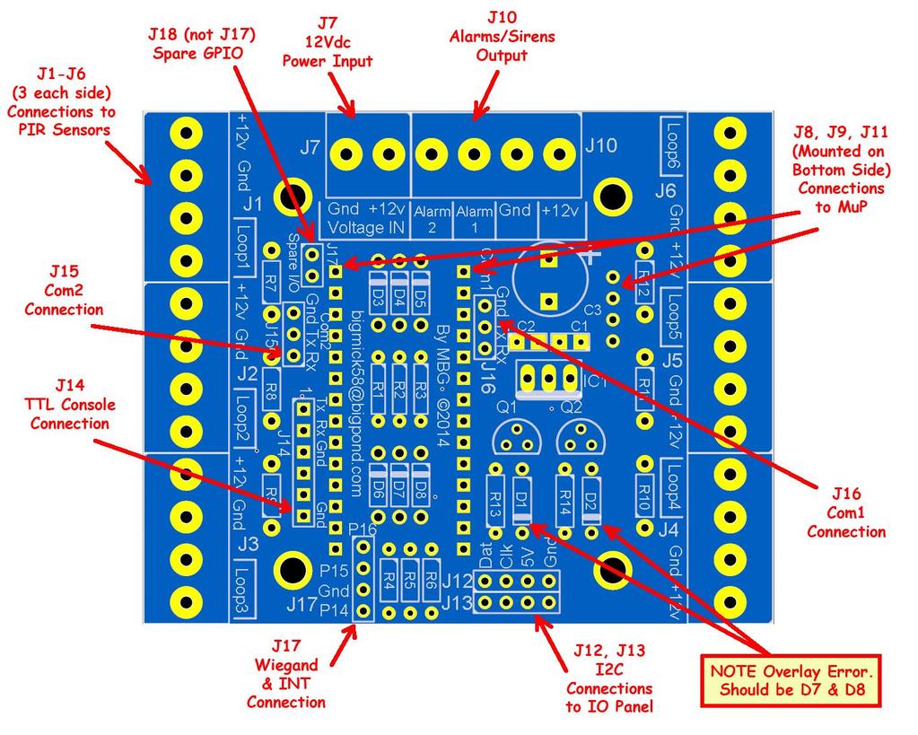
2 Preamble: The MuP-Security project came about due to a request from David Hall, a member of `The Back Shed Forum, for a board that could plug into MuP to provide the basis of a home and/or shop security system. He had a specific need for a cheap, well featured alarm controller and graciously sponsored the design and prototyping of what is now known as MuP- Security. MuP-Security is 76mm x 61mm (3 x 2.4 ) and will bolt directly on top of a MuP CPU Board. Information on MuP can be found on `The Back Shed Forum using the following URL: As at the time of writing (Aug-2014) there is no available `ready-to-run software to run this board but it is in the process of being written and, hopefully, a release will be out by the end of August Any software releases/updates will be published on `The BackShed Forum (microcontroller and PC Projects section) linked here: MuP-Security will NOT function by itself and requires MuP for the `smarts of the project, as well as the, I 2 C controlled, `IO Panel for the user interfaces. Board Concept: The general theory behind using MuP as the basis for a security system is, by using ANALOG inputs, it is possible to measure voltages across a voltage divider made up of several resistors. Take a typical alarm sensor circuit, as shown below:
3 It can be seen that in a normal, non-triggered sensor, situation that we would have the following situation, (Ignore R1 as the Analog input has a relatively high input impedance). 3v3 through R2 then through a closed sector relay (R3 shorted out) then through R4 to GND. This effectively gives us a simple 2 series resistor voltage divider and should give us a reading of (3.3/2) 1.65v. If the sector is triggered then this would add R3 into the series of resistors and the reading at the Analog input should be (3.3 x 2/3) 2.2v. If however someone cuts the wires to the sensor or tampers with its casing the tamper switch would open and break the connection to GND meaning that the full 3v3 should be read at the Analog input. Using that theory it is possible to monitor the above scenarios very easily using just the one Analog input. We have used 6 Analog inputs which will allow 6 `standard wired sensors or 12 `zone doubled sensors. Zone doubling basically means that another PIR sensor is paralleled across the first but by using different resistor values for R3 and R4 we can determine which of the 2 sensors has been triggered. Note, zone doubling alters the voltage readings seen at the Analog input and these will be different to those of single zone reading. Input Protection: We have provided over voltage input protection to each of the 6 Analog inputs by means of fast switching Shotky diodes just in case of a wiring error when installing the sensors. Switched Outputs: Two transistor driven switched outputs (12v output level) are provided to drive sirens, alarms, strobes etc. either directly, if under 500mA each, or via external relay circuitry. I 2 C User interface Panel: (J12 & J13) Due to the lack of IO lines for the features that we wanted, we have opted to use an I 2 C controlled user interface Panel. The IO Panel allows the MuP to use only 2 IO pins to drive a 20x4 LCD module, 8 indication LEDs and a 4x4 matrix keypad. TTL Serial Interfaces: (J15 & J16) We have brought out MuP TTL serial ports (Com1 and Com2) to 3 pin headers for connection to external devices such as a GPS module and 3G Dialer. Com1: (J16) Connection to GSM/GPRS or modem using standard AT commands to send text alerts, alerts for alarms on / off Com2: (J15) Optional connection to GPS for location based tracking / time synchronisation etc.
4 Weigand Interface: (J17) We have brought out 2 IO pins (Pin15 & 16) to J17 along with GND in the hope that we can support what is generally a high-end user input console. As this protocol is not supported by the MicroMite s MMBasic directly, we hope to be able to `bit-bang the Wiegand protocol, if this is not possible then we have two extra IO pins available there for general use. Interrupt from IO Panel: (J17) The IO Panel has the facility to set an interrupt pin LOW if a key has been pressed, this can be useful in letting MuP know that a key has been pressed and that it needs to service the keypad routine. Spare IO Lines: (J18): Note J18 is labelled incorrectly as J17 (on the PCB) and is located near R7 in the upper left region of the PCB. As we found that we still had 2 IO lines left after we had laid out the PCB we decided it was better to give these a home so we ran Pin(24) and Pin(25) to this header for General IO. BOM: Reference Type Description Reference Type Description C1 100nF 0.1" footprint Q1 BC337 NPN TRANSISTOR C2 100nF 0.1" footprint Q2 BC337 NPN TRANSISTOR C3 1000uF -16v/25v Electrolytic 0.2" spacing R1 1K 1/4 Watt D7 1N V 1A Rectifier R2 1K 1/4 Watt D8 1N V 1A Rectifier R3 1K 1/4 Watt IC1 LM7805 5V Reg TO-220 R4 1K 1/4 Watt J1 Screw Jack 4 Pole 0.2" (5.08mm) Pitch R5 1K 1/4 Watt J2 Screw Jack 4 Pole 0.2" (5.08mm) Pitch R6 1K 1/4 Watt J3 Screw Jack 4 Pole 0.2" (5.08mm) Pitch R7 4.7K 1/4 Watt J4 Screw Jack 4 Pole 0.2" (5.08mm) Pitch R8 4.7K 1/4 Watt J5 Screw Jack 4 Pole 0.2" (5.08mm) Pitch R9 4.7K 1/4 Watt J6 Screw Jack 4 Pole 0.2" (5.08mm) Pitch R10 4.7K 1/4 Watt J7 Screw Jack 2 Pole 0.2" (5.08mm) Pitch R11 4.7K 1/4 Watt J8 14 Pin SIP (Female) Mounted on Rear R12 4.7K 1/4 Watt J9 14 Pin SIP (Female) Mounted on Rear R13 1K 1/4 Watt J10 Screw Jack 4 Pole 0.2" (5.08mm) Pitch R14 1K 1/4 Watt J11 4 Pin SIP (Female) Mounted on Rear D1 1N5819 LDO Schotky 40V 1A J12 4 Pin SIP (Male) I 2 C Header D2 1N5819 LDO Schotky 40V 1A J13 4 Pin SIP (Male) I 2 C Header D3 1N5819 LDO Schotky 40V 1A J14 6 Pin SIP (Male) TTL Serial I'face D4 1N5819 LDO Schotky 40V 1A J15 3 Pin SIP (Male) Com2 Interface D5 1N5819 LDO Schotky 40V 1A J16 3 Pin SIP (Male) Com1 Interface D6 1N5819 LDO Schotky 40V 1A J17 4 Pin SIP (Male) Weigard/GPIO I'face J18 2 Pin SIP (Male) General IO (Spare
5 Schematic: TTL Serial Console (J14): We have provided a header, J14, to provide easy access to the MMBasic on MuP so that the controlling program can be updated. This header conforms to the standard header J2 on MuP itself except that none of the voltages (5v or 3v3) are connected due to the relatively heavy loads that can be connected to MuP-Security, as such to communicate with MuP it will be necessary to also have MuP-Security powered via the 12Vdc power source.
6 Construction: Building MuP Security is very straight forward, the only consideration to be careful of is that headers J8, J9 and J11 are mounted on the bottom layer of the IO Panel, these are to mate with MuP and transfers all of the required signals between the two boards. We recommend mounting these headers last so that they don t get damaged in the soldering process. A standard TO-220 heat sink needs to be fitted to the LM7805 regulator but we recommend fitting it facing backwards, towards the bottom of the PCB (towards Q1 and Q2), so that Com1 is easily accessible. A small blob of `hot melt glue or silicone between the heat sink and C1 will stop the heat sink from being bent down and shorting against anything. Power Source: MuP-Security expects that the input power source (which will get transferred to the remote sensors as well) to be 12Vdv and of sufficient current to drive the entire circuit including MuP, MuP-Security, IO-Panel, any sirens/alarms/strobes etc and all of the remote sensors. We can t comment on current draw for the sensors and sirens but you should allocate at least 1A for all of the control circuitry. Our suggestion would be to use a 12Vdc (3A or 5A) power supply. Mup-Security regulates the 12Vdc down to 5Vdc and in turns transmits this to MuP via header J11, MuP regulates this to 3v3 to power not only MuP but MuP-Security as well.
Installation/assembly manual for DCC/Power shield
 Installation/assembly manual for DCC/Power shield The DCC circuit consists of the following components: R1/R6 R2/R3 R4/R5 D1 C2 2 kω resistor ½ Watt (colour code Red/Black/Black/Brown/Brown) 10 kω resistor
Sierra Radio Systems. HamStack. Project Board Reference Manual V1.0
 Sierra Radio Systems HamStack Project Board Reference Manual V1.0 Welcome HamStack Project Board Reference Manual Revision 1.0.3 2011 George Zafiropoulos, KJ6VU and John Best, KJ6K This guide provides
Schematic Diagram: R2,R3,R4,R7 are ¼ Watt; R5,R6 are 220 Ohm ½ Watt (or two 470 Ohm ¼ Watt in parallel)
") Nano DDS VFO Rev_2 Assembly Manual Farrukh Zia, K2ZIA, 2016_0130 Featured in ARRL QST March 2016 Issue Nano DDS VFO is a modification of the original VFO design in Arduino Projects for Amateur Radio by
Nano DDS VFO Rev_2 Assembly Manual Farrukh Zia, K2ZIA, 2016_0130 Featured in ARRL QST March 2016 Issue Nano DDS VFO is a modification of the original VFO design in Arduino Projects for Amateur Radio by
solutions for teaching and learning
 RKP18Motor Component List and Instructions PCB layout Constructed PCB Schematic Diagram RKP18Motor Project PCB Page 1 Description The RKP18Motor project PCB has been designed to use PIC microcontrollers
Chill Interface PCB Assembly Instructions
 ExcelValley Chill Interface PCB Waveblaster Module MIDI Interface Board Chill Limited Edition V2 Assembly Kit Standalone midi interface board for Waveblaster synthesizer modules. Suitable for most Waveblaster
MuP-VT. By Mick Gulovsen 11-Sep-2014 Ver. 1
 MuP-VT By Mick Gulovsen 11-Sep-2014 Ver. 1 bigmick58@bigpond.com Board Concept. MuP-VT is a small 49.5mm x 49.5mm PCB that is based on Geoff Graham s ASCII Video Terminal (AVT), which is a VT100 based
SM010, Assembly Manual PCB Version 1.0
 180 SM010, Assembly Manual MATRIXARCHATE 16 8 IO SEQUENTIAL MATRIX SIGNAL ROUTER SM010 1 2 1 2 3 4 5 3 4 5 6 7 8 9 10 11 12 6 7 8 9 10 11 12 13 14 15 16 PROGRAM A B C D E F G H f1 f2 20.000 180 SSSR Labs
KIT 134. INTRODUCTION TO LCD S
 The aim of this kit is to show how to use a 16x2 alphanumeric Liquid Crystal Display (LCD) with a PC. First we show how to connect it to the parallel port and echo and handle keyboard input. Then we show
Figure 3.0, Schematic for display application
 Including lighting for model railroad water towers, bridge, runway, running and crossing lights, rolling hardware and storefront dress-up lights are now easy then ever. While there are several kits readily
Ultimate LPF kit: Relay-switched LPF kit
 Ultimate LPF kit: Relay-switched LPF kit PCB Revision 4 1. Introduction Thank you for purchasing the QRP Labs relay-switched low-pass filter (LPF) kit. This kit is designed to complement the Ultimate3
MedeaWiz 8X78. Input / Output Expander. FW version 1.0. PCB version 1.0. Manual version Note that this manual may change periodically
 MedeaWiz 8X78 Input / Output Expander FW version 10 PCB version 10 Manual version 110 Note that this manual may change periodically Please go to wwwmedeawizcom for the latest version 0 P a g e Table of
SRI-02 Speech Recognition Interface
 SRI-02 Speech Recognition Interface Data & Construction Booklet The Speech Recognition Interface SRI-02 allows one to use the SR-07 Speech Recognition Circuit to create speech controlled electrical devices.
Propeller Project Board USB (#32810)
") Web Site: www.parallax.com Forums: forums.parallax.com Sales: sales@parallax.com Technical: support@parallax.com Office: (916) 624-8333 Fax: (916) 624-8003 Sales: (888) 512-1024 Tech Support: (888) 997-8267
Web Site: www.parallax.com Forums: forums.parallax.com Sales: sales@parallax.com Technical: support@parallax.com Office: (916) 624-8333 Fax: (916) 624-8003 Sales: (888) 512-1024 Tech Support: (888) 997-8267
Sierra Radio Systems. Digital Compass. Reference Manual. Version 1.0
 Sierra Radio Systems Digital Compass Reference Manual Version 1.0 Contents Digital compass board RS485 power injector For more information, go to the Sierra Radio Systems web site at www.sierraradio.net
DEV-1 HamStack Development Board
 Sierra Radio Systems DEV-1 HamStack Development Board Reference Manual Version 1.0 Contents Introduction Hardware Compiler overview Program structure Code examples Sample projects For more information,
TKEY-1. CW touch key. (no electromechanical contacts) Assembly manual. Last update: June 20,
 Assembly manual. Last update: June 20,") TKEY-1 CW touch key (no electromechanical contacts) Assembly manual Last update: June 20, 2017 ea3gcy@gmail.com Updates and news at: www.ea3gcy.com Thanks for constructing the TKEY-1A CW touch key Have
TKEY-1 CW touch key (no electromechanical contacts) Assembly manual Last update: June 20, 2017 ea3gcy@gmail.com Updates and news at: www.ea3gcy.com Thanks for constructing the TKEY-1A CW touch key Have
Shack Clock kit. U3S Rev 2 PCB 1. Introduction
 Shack Clock kit U3S Rev 2 PCB 1. Introduction Thank you for purchasing the QRP Labs Shack Clock kit. This clock uses the Ultimate3S QRSS/WSPR kit hardware, but a different firmware version. It can be used
4.0 Blue LED DCF77 Clock documentation
 4.0 Blue LED DCF77 Clock documentation 1. LED Clock Main Board PCB mounting: Mount and solder the eight wire bridges. Mount and solder resistors R16, R18, R20, R22. Mount and solder capacitors C1 C3 (pitch
The FED PIC Flex 2 Development Boards
 The FED PIC Flex 2 Development Boards THE FED PIC Flex Development board offers a host for 28 or 40 pin devices and includes LED's, switches, transistor switches, USB interface, serial port, support circuitry,
Rapid28iXL PIC Prototyping PCB User Manual
 Description Features This is a PCB designed to facilitate the rapid prototyping of a device based on a 28 pin Microchip PIC microcontroller. To allow users to focus on their application, we take care of
DEV16T. LCD Daughter board
 LCD Daughter board Table of Contents 1 Introduction...2 2 Features...3 3 Expansion Connectors...4 3.1 Daughter Board Connectors...4 4 LCD Display...5 5 Input Buttons S1 to S4...5 6 Buzzer...5 7 Connector
KK1L 2x6 Antenna Switch Relay Controller / Dual Band Decoder Basic Assembly Version 4.8 (new 24-Aug-2009) Parts List updated 19-AUG-2016
 Parts List updated 19-AUG-2016") KK1L 2x6 Antenna Switch Relay Controller / Dual Band Decoder Basic Assembly Version 4.8 (new 24-Aug-2009) Parts List updated 19-AUG-2016 Ronald Rossi, KK1L http://home.comcast.net/~kk1l Design Features:
KK1L 2x6 Antenna Switch Relay Controller / Dual Band Decoder Basic Assembly Version 4.8 (new 24-Aug-2009) Parts List updated 19-AUG-2016 Ronald Rossi, KK1L http://home.comcast.net/~kk1l Design Features:
Rapid40iXL PIC Prototyping PCB User Manual
 Description This is a PCB designed to facilitate the rapid prototyping of a device based on a 40 pin Microchip PIC microcontroller. To allow users to focus on their application, we take care of key housekeeping
BUILDING YOUR KIT. For the Toadstool Mega328.
 BUILDING YOUR KIT For the Toadstool Mega328 www.crash-bang.com @crashbang_proto This work is licensed under a Creative Commons Attribution-ShareAlike 4.0 International License. Congratulations! You re
Arduino Uno. Arduino Uno R3 Front. Arduino Uno R2 Front
 Arduino Uno Arduino Uno R3 Front Arduino Uno R2 Front Arduino Uno SMD Arduino Uno R3 Back Arduino Uno Front Arduino Uno Back Overview The Arduino Uno is a microcontroller board based on the ATmega328 (datasheet).
Manual Main PCB Small-MIDI 4
 Index PARTLIST MAIN PCB... 2 INTRODUCTION... 3 GENERAL... 3 THE CIRCUIT... 3 ASSEMBLY KIT... 4 ASSEMBLY OF THE PCB... 4 An important tip...... 4 ASSEMBLY... 4 THE CONNECTORS... 4 Power supply J1... 4 IDC
RibEye Multi-Point Deflection Measurement System 3-Axis Version for the SIDIIs ATD Hardware Manual for Model January 2010
 USER S MANUAL RibEye Multi-Point Deflection Measurement System 3-Axis Version for the SIDIIs ATD Hardware Manual for Model 7715 15 January 2010 Boxboro Systems, LLC 978-257-2219 www.boxborosystems.com
midon design A 1-Wire Multi-purpose Sensor 1WIO Figure 1 MD2083 As-Shipped August 23, WIO User Guide Version 1.
 A 1-Wire Multi-purpose Sensor 1WIO Figure 1 MD2083 As-Shipped August 23, 2009 1WIO User Guide Version 1.7 Page 1 of 14 1WIO User Guide Version 1.7 1. Table of Contents 1. Table of Contents...2 1.1. List
SPIRIT. Phase 5 Analog Board Computer and Electronics Engineering
 SPIRIT Phase 5 Analog Board Computer and Electronics Engineering In this exercise you will assemble the analog controller board and interface it to your TekBot. Print out the schematic, silkscreen and
K191 3 Channel RGB LED Controller
 K191 3 Channel RGB LED Controller 1 Introduction. This kit has been designed to function as a versatile LED control module. The LED controller provides 3 high current channels to create light effects for
REN816XB David Haberle 2010 (Dirknerkle)
") REN816XB David Haberle 2010 (Dirknerkle) www.diychristmas.org The REN816XB is a wireless 8 or 16 channel wireless data Christmas light controller. It is based on the Renard SS16 design- it's essentially
REN816XB David Haberle 2010 (Dirknerkle) www.diychristmas.org The REN816XB is a wireless 8 or 16 channel wireless data Christmas light controller. It is based on the Renard SS16 design- it's essentially
Advanced Strobe 1.0 Kit
 Kit Instruction Manual Eastern Voltage Research, LLC December 2013, Rev 1 1 http://www.easternvoltageresearch.com Kit Introduction to the Kit Thank you for purchasing the Kit. If you are looking for a
[Note: Power adapter is not included in the kits. Users need to prepare a 9 12 V ( >300mA capacity ) DC power supply]
![[Note: Power adapter is not included in the kits. Users need to prepare a 9 12 V ( >300mA capacity ) DC power supply]](/thumbs/76/74094055.jpg "[Note: Power adapter is not included in the kits. Users need to prepare a 9 12 V ( >300mA capacity ) DC power supply]") 062 LCD Oscilloscope Assembly Notes Applicable Models: 06203KP, 06204KP DN062-18v02 Important Notes 1. Some components shown in the schematic and PCB layout are for options or adjustments. They do not
062 LCD Oscilloscope Assembly Notes Applicable Models: 06203KP, 06204KP DN062-18v02 Important Notes 1. Some components shown in the schematic and PCB layout are for options or adjustments. They do not
8051 Intermidiate Development Board. Product Manual. Contents. 1) Overview 2) Features 3) Using the board 4) Troubleshooting and getting help
 Overview 2) Features 3) Using the board 4) Troubleshooting and getting help") 8051 Intermidiate Development Board Product Manual Contents 1) Overview 2) Features 3) Using the board 4) Troubleshooting and getting help 1. Overview 2. Features The board is built on a high quality FR-4(1.6
8051 Intermidiate Development Board Product Manual Contents 1) Overview 2) Features 3) Using the board 4) Troubleshooting and getting help 1. Overview 2. Features The board is built on a high quality FR-4(1.6
HARDWARE MANUAL TMCM-1613 TMCM-1613-REC. Hardware Version V TRINAMIC Motion Control GmbH & Co. KG Hamburg, Germany.
 MODULES FOR BLDC MOTORS MODULES Hardware Version V 1.10 HARDWARE MANUAL + + TMCM-1613 + + Single Axis BLDC Controller / Driver Block-commutation Hall-sensor based Analog+digital inputs / outputs Up-to
Module 3B: Arduino as Power Supply
 Name/NetID: Teammate/NetID: Module 3B: Laboratory Outline As you work on through the labs during the semester and some of the modules you may want to continue experimenting at home. Luckily the microprocessor
Ca Bling! Pacificon 2011 Norcal Buildathon Project
 Ca Bling! Pacificon 2011 Norcal Buildathon Project 10/23/2011 ver 1.1 by W1REX / QRPme www.qrpme.com The Ca Bling! Kit is a small Picaxe micro controller development board designed by W1REX as a project
Rapid40i PIC Prototyping PCB User Manual
 Description This is a PCB designed to facilitate the rapid prototyping of a device based on a 40 pin Microchip PIC microcontroller. To allow users to focus on their application, we take care of key housekeeping
Blue Point Engineering
 Blue Point Engineering Board - Pro Module (E) Instruction Pointing the Way to Solutions! Controller I Version 2.1 The Board Pro E Module provides the following features: Up to 4 minutes recording time
AVR Intermediate Development Board. Product Manual. Contents. 1) Overview 2) Features 3) Using the board 4) Troubleshooting and getting help
 Overview 2) Features 3) Using the board 4) Troubleshooting and getting help") AVR Intermediate Development Board Product Manual Contents 1) Overview 2) Features 3) Using the board 4) Troubleshooting and getting help 1. Overview 2. Features The board is built on a high quality FR-4(1.6
AVR Intermediate Development Board Product Manual Contents 1) Overview 2) Features 3) Using the board 4) Troubleshooting and getting help 1. Overview 2. Features The board is built on a high quality FR-4(1.6
Bolt 18F2550 System Hardware Manual
 1 Bolt 18F2550 System Hardware Manual Index : 1. Overview 2. Technical specifications 3. Definition of pins in 18F2550 4. Block diagram 5. FLASH memory Bootloader programmer 6. Digital ports 6.1 Leds and
ARDUINO MEGA ADK REV3 Code: A000069
 ARDUINO MEGA ADK REV3 Code: A000069 OVERVIEW The Arduino MEGA ADK is a microcontroller board based on the ATmega2560. It has a USB host interface to connect with Android based phones, based on the MAX3421e
DIY Line Tracking Smart Car with AT89C2051
 DIY Line Tracking Smart Car with AT89C2051 1. Introduction: A DIY Smart Car design involves mechanical structure, electronic based sensor principle, automatic control, and even knowledge of microcontroller
CHAPTER 5. Voltage Regulator
 CHAPTER 5 Voltage Regulator In your robot, the energy is derived from batteries. Specifically, there are two sets of batteries wired up to act as voltage sources; a 9V battery, and two 1.5V batteries in
LLIA90 LED ARRAY 90 LED Array Illuminator. LLIA90 LED Illuminator Array
 LLIA90 LED Illuminator Array The LLIA90 is a high-quality and high-performance multi-purpose LED illuminator array. It has a built-in regulator and a photocell control circuit for automatic LED array on/off
PedalSync. 9 Switches MV-62. Chip. Module. and
 PedalSync 9 Switches MV-62 Chip and Module PedalSync 9 Switches chip MV-62 is designed for pedalboard switching controls using the extremely quiet PedalSync MV-57 ReMute Relay Bypass system. MV-62 works
The Bluetooth Controlled Relay Board & Speech Recognition Sets
 The Bluetooth Controlled Relay Board & Speech Recognition Sets Brought to you by: ENGINEERINGSHOCK ELECTRONICS Bluetooth Speech Module Features: 1) 10x Controllable Outputs 2) LCD Display 3) Arduino Compatible
HUB-ee BMD-S Arduino Proto Shield V1.1
 HUB-ee BMD-S Arduino Proto Shield V1.1 User guide and assembly instructions Document Version 0.5 Introduction & Board Guide 2 Schematic 3 Quick User Guide 4 Assembly Guide 6 Kit Contents 7 1) Diodes and
C45 - LIMIT AND HOME UNIVERSAL BOARD Rev. 1
 C45 - LIMIT AND HOME UNIVERSAL BOARD Rev. 1 User manual Rev. 1 1. Overview This card provides an easy means of connecting optical, mechanical and proximity sensor to operate as homing and limit switches
12v Power Controller Project Board
 12v Power Controller Project Board 12 Volt Power Controller Introduction This board provides three functions... DC power gate Low voltage disconnect Voltage / current display The typical usage for this
TurboTaig Instruction Manual
 TurboTaig Instruction Manual Version: 2.2 Peter Homann 20 View St Highett 3190 homann@smartchat.net.au http://people.smartchat.net.au/~homann 1 Table of Contents Table of Contents... 2 Introduction...
Number Name Description Notes Image 0101 Resistor, 100 ohm. brown-black-browngold. ¼ watt, 5% tolerance, red-red-brown-gold. brown-black-red-gold.
 Passive Components 0101 Resistor, 100 brown-black-browngold. 690620 0102 Resistor, 220 red-red-brown-gold. 690700 0103 Resistor, 1000 brown-black-red-gold. 690865 0104 Resistor, 10k 0201 Capacitor, 1 µf,
QUASAR KIT No DIGITAL DOWN TIMER 99 MIN WITH PIC
 QUASAR KIT No 1173 - DIGITAL DOWN TIMER 99 MIN WITH PIC KIT 1173 is a digital countdown timer based on a micro controller, thus securing reliability and excellent operation under any circumstances. It
EBF31A Assembly Instructions
 EBF31A Assembly Instructions Revision v0.2 07/09/2014 Seth Neumann, sneumann@pacbell.net Introduction This document describes the functional blocks of the EBF31A and how to assemble it. Revision History
Arduino ADK Rev.3 Board A000069
 Arduino ADK Rev.3 Board A000069 Overview The Arduino ADK is a microcontroller board based on the ATmega2560 (datasheet). It has a USB host interface to connect with Android based phones, based on the MAX3421e
Pololu 12V Step-Up/Step-Down Voltage Regulator S10V2F12
 Pololu 12V Step-Up/Step-Down Voltage Regulator S10V2F12 Overview The Pololu step-up/step-down voltage regulator S10V2F12 is a switching regulator (also called a switched-mode power supply (SMPS) or DC-to-DC
K8099 NIXIE CLOCK. * optional enclosure TKOK19 (black) - TKOK17 (white) ** optional plexiglass enlcosure B8099 ILLUSTRATED ASSEMBLY MANUAL
 - TKOK17 (white) ** optional plexiglass enlcosure B8099 ILLUSTRATED ASSEMBLY MANUAL") Total solder points: 230 + 74 Difficulty level: beginner 1 2 3 4 5 advanced NIXIE CLOCK K8099 ** * A unique combination of both vintage and modern electronics ILLUSTRATED ASSEMBLY MANUAL H8099IP-1 * optional
Total solder points: 230 + 74 Difficulty level: beginner 1 2 3 4 5 advanced NIXIE CLOCK K8099 ** * A unique combination of both vintage and modern electronics ILLUSTRATED ASSEMBLY MANUAL H8099IP-1 * optional
ES-362U PRESETTABLE MASTER TIMER
 142 SIERRA ST., EL SEGUNDO, CA 90245 USA (310)322-2136 FAX (310)322-8127 www.ese-web.com ES-362U PRESETTABLE MASTER TIMER OPERATION AND MAINTENANCE MANUAL The ES-362U is a four digit, presettable 100 minute
Electronic Lock CodeLock AVR 1 DIY electronic door lock
 Electronic Lock CodeLock AVR 1 DIY electronic door lock CodeLock AVR LCD CodeLock AVR electronic lock is realised with Atmel AVR micro-controller AT90S2313, ATtiny2313 or ATtiny45. 1 user code in the program
PCB-AVR1284-3U. AVR Microcontroller Development PCB for Atmel 40-pin DIP AVRs.
 PCB-AVR1284-3U AVR Microcontroller Development PCB for Atmel 40-pin DIP AVRs. Part Number: PCB-AVR1284-3U (unpopulated PCB, no parts) Features A development board for Atmel 40 pin AVR microcontrollers.
Fuzz Rite V2.0. Mosrite FuzzRite / Gus Rite Fuzz
 Fuzz Rite V2.0 Mosrite FuzzRite / Gus Rite Fuzz Contents of this document are 2016 Pedal Parts Ltd. No reproduction permitted without the express written permission of Pedal Parts Ltd. All rights reserved.
Butterfly Laser Diode Mount
 LM14S2 Butterfly Laser Diode Mount Operating Manual LM14S2 Laser On TEC Driver LD Driver THORLABS, Inc. Ph: (973) 579-7227 435 Route 206N Fax: (973) 383-8406 Newton, NJ 07860 USA www.thorlabs.com 10614-D02
Universal Keying Adapter 3+
 Universal Keying Adapter 3+ The Universal Keying Adapter Version 3+ kit will allow you to key nearly any transmitter or transceiver with a straight key, electronic keyer, computer serial or parallel port
Two-wire. Jumper for 12V. J2 Enable Adjust D/A1. Super PLC Warning: Warranty Void if this label is damaged 62256LP-12 CMOS RAM 4.
 T100MD-888+ PLC Installation Guide LCD Display Module 1N4007 (optional) + - 12 to 24V DC Power Supply for PLC Contrast Adjust 14-pin LCD Display port Two-wire RS485 + - Jumper for 12V 1000µ F 5 E.Cap (Optional)
The PUMPKIN LIGHT LED
 The PUMPKIN LIGHT LED PUMPKIN LIGHT LED By Mark McCuller Email: mcculler@mail.com DESIGN SUMMARY The PUMPKIN LIGHT LED By: Mark McCuller The Pumpkin Light LED is a battery-powered device that illuminates
Building the Super-VMW CPU Meter by Vincent M. Weaver 18 May 2011
 Building the Super-VMW CPU Meter http://www.deater.net/weave/vmwprod/meter/super.html by Vincent M. Weaver 18 May 2011 1 Parts List Part No Description Quantity Source LED Board 1 SVMW-Meter-LED-Board
T100MD PLC Installation Guide
 T100MD-2424+ PLC Installation Guide LCD Display Module MCR 12 to 24V DC Power Supply for PLC Master Control Relay for Output. + - EEPROM Write-Protection when J2 at WP 14-pin LCD Display Port Two-wire
RASPBERRY PI MEGA-IO EXPANSION CARD USER'S GUIDE VERSION 2.3
 RASPBERRY PI MEGA-IO EXPANSION CARD www.sequentmicrosystems.com USER'S GUIDE VERSION 2.3 GENERAL DESCRIPTION... 2 BOARD LAYOUT... 3 BLOCK DIAGRAM... 4 COMPONENT DESCRIPTION... 5 CONFIGURATION JUMPERS...
ARDUINO MEGA 2560 REV3 Code: A000067
 ARDUINO MEGA 2560 REV3 Code: A000067 The MEGA 2560 is designed for more complex projects. With 54 digital I/O pins, 16 analog inputs and a larger space for your sketch it is the recommended board for 3D
Vout R LED2 LED1 Nr. of LEDs R Ohm Current ma Vout V Ardunio Pin9
 Tutorial AR Drone Miru Mod on Windows 7 with DX6i, Part 5 V. UFO Doctor, Aug th, 0 7. VLBA experiments with external LED at Arduino Pin9 Introduction Miru Mod 008 offered us the Visible Low Battery Alert
ES-562/564U COMBINATION CLOCK/TIMER
 142 SIERRA ST., EL SEGUNDO, CA 90245 USA (310)322-2136 FAX (310)322-8127 www.ese-web.com ES-562/564U COMBINATION CLOCK/TIMER OPERATION AND MAINTENANCE MANUAL The ES-562U/564U is a combination six digit
MIDI CPU Hardware Rev K. User Manual
 MIDI CPU Hardware Revision K User Manual Updated 2010-09-08 Additional documentation available at: http://highlyliquid.com/support/ Page 1 / 18 Table of Contents 1.0 Important Safety Information...2 2.0
PLCADD1616 User Guide 3/29/10. Overview
 PLCADD1616 User Guide 3/29/10 Overview The PLCADD1616 is a PLC expansion board used to add digital inputs and outputs to a compatible host PLC. The PLCADD1616 has 16 relay outputs and 16 optically isolated
Flight Data Recorder Hardware Version 1.0
 Flight Data Recorder Hardware Version 1.0 By R. G. Sparber Scope The Flight Data Recorder (FDR) hardware is described here. The software is described in a separate document. The reader can etch their own
W0EB/W2CTX DSP Audio Filter Construction Manual V3.02.1
 W0EB/W2CTX DSP Audio Filter Construction Manual V3.02.1 Manual and photographscopyright W0EB/W2CTX, January 01, 2019. This document may be freely copied and distributed so long as no changes are made and
RB-Pol V, 300mA Step-Down Voltage Regulator D24V3F3
 RB-Pol-220 3.3V, 300mA Step-Down Voltage Regulator D24V3F3 The compact (0.4 0.5 ) D24V3F3 switching step-down (or buck) voltage regulator takes an input voltage between 4.3 V and 42 V and efficiently reduces
AUDIO AMPLIFIER PROJECT
 Intro to Electronics 110 - Audio Amplifier Project AUDIO AMPLIFIER PROJECT In this project, you will learn how to master a device by studying all the parts and building it with a partner. Our test subject:
Button Code Kit. Assembly Instructions and User Guide. Single Button Code Entry System
 Button Code Kit Single Button Code Entry System Assembly Instructions and User Guide Rev 1.0 December 2009 www.alan-parekh.com Copyright 2009 Alan Electronic Projects Inc. 1. Introduction... 4 1.1 Concept
ARDUINO LEONARDO WITH HEADERS Code: A000057
 ARDUINO LEONARDO WITH HEADERS Code: A000057 Similar to an Arduino UNO, can be recognized by computer as a mouse or keyboard. The Arduino Leonardo is a microcontroller board based on the ATmega32u4 (datasheet).
Advanced Lantern 1.0 Kit. Introduction to the Advanced Lantern 1.0 Kit
 Advanced LED Lantern 1.0 Instruction Manual Eastern Voltage Research, LLC Introduction to the Advanced Lantern 1.0 Kit Thank you for purchasing the Advanced Lantern 1.0 Kit. This kit is an advanced microprocessor
ACORN User Guide For Revision (Aka Acorn_rev3) Updated 1/23/17
 Updated 1/23/17") ACORN User Guide For Revision 171025 (Aka Acorn_rev3) Updated 1/23/17 Overview ACORN is technically a breakout board for the BeagleBone Green or BeagleBone Black embedded computer. The remainder of this
ACORN User Guide For Revision 171025 (Aka Acorn_rev3) Updated 1/23/17 Overview ACORN is technically a breakout board for the BeagleBone Green or BeagleBone Black embedded computer. The remainder of this
ZEUS Series: microzeus with Flying Bus Boards
 ZEUS Series: microzeus with Flying Bus Boards Zeus Series: microzeus with Flying Bus Boards The uzeus is a 4HP power supply module for Eurorack format synthesizers. This version comes with two (2) flying
HARDWARE OPERATIONS MANUAL
 HARDWARE OPERATIONS MANUAL Table of Contents INTRODUCTION... 2 SECTION 1: HARDWARE COMPONENT ASSEMBLIES... 2 MECHANICAL HARDWARE AND CASE... 2 PCB ASSEMBLY... 4 ISD RECORDING CIRCUIT... 5 BREADBOARD ASSEMBLY...
Adafruit USB Power Gauge Mini-Kit
 Adafruit USB Power Gauge Mini-Kit Created by Bill Earl Last updated on 2017-07-14 11:55:04 PM UTC Guide Contents Guide Contents Overview Assembly Basic Assembly Solder the female connector. Solder the
Modtronix Engineering Modular Electronic Solutions SBC28DC. Single board computer for 28 pin DIP PICs
 Modtronix Engineering Modular Electronic Solutions Single board computer for 28 pin DIP PICs Table of Contents 1 Introduction...2 2 Features...4 3 Expansion Connectors...5 3.1 Daughter Board Connectors...5
Table of Contents 1 ABOUT THIS GUIDE CONTACT INFORMATION ANTENNA INSTALLATION... 4
 Table of Contents 1 ABOUT THIS GUIDE... 3 1.1 CONTACT INFORMATION... 3 2 ANTENNA INSTALLATION... 4 2.1 GENERAL INFORMATION... 4 2.2 SPECIFIC MOUNTING EXAMPLES... 5 2.3 CONNECTOR MOISTURE PROTECTION...
ARDUINO UNO REV3 SMD Code: A The board everybody gets started with, based on the ATmega328 (SMD).
.") ARDUINO UNO REV3 SMD Code: A000073 The board everybody gets started with, based on the ATmega328 (SMD). The Arduino Uno SMD R3 is a microcontroller board based on the ATmega328. It has 14 digital input/output
ARDUINO UNO REV3 SMD Code: A000073 The board everybody gets started with, based on the ATmega328 (SMD). The Arduino Uno SMD R3 is a microcontroller board based on the ATmega328. It has 14 digital input/output
Exclusive 2.5 GHz Frequency Counter
 Exclusive 2.5 GHz Frequency Counter with blue 2 x 16 LCD display This manual will guide you how to assemble, test and tune this frequency counter KIT. Features: Frequency range from 5 MHz to 2.5GHz Factory
PLATINUM SERIES R PART NUMBER SELECTION. High performance SPDT up to 40 GHz. Our Most Important Connection is with You. SMA - SMA 2.
 PART NUMBER SELECTION Frequency Range: 3: SMA up to 6 GHz 4: SMA up to 20 GHz F: SMA up to 26.5 GHz 8: SMA 2.9 up to 40 GHz Type: 3: Latching (1) 4: Latching + I.C. (1) 5: Latching + S.C.O. (1) 6: Latching
Construction Construction Instructions
 Semi-Virtual Diskette SVD Construction Construction Instructions PCB version 2.0 September 2004 Eric J. Rothfus Table of Contents Table of Contents... i Parts List...1 Construction Overview...5 PCB Construction...
TIME WIZARD MULTI CLOCK DIVIDER BUILDING GUIDE
 TIME WIZARD MULTI CLOCK DIVIDER BUILDING GUIDE Table of Contents 0. Components List + Tools 0. PCB Sides 03. PCB Assembly 04_. Diode N448 04_. Laying Resistors 04_3. Capacitors 04_4. Quartz 04_5. 78L05
QRPometer Assembly Manual Copyright 2012 David Cripe NM0S The 4 State QRP Group. Introduction
 QRPometer Assembly Manual Copyright 2012 David Cripe NM0S The 4 State QRP Group Introduction Thank you for purchasing a QRPometer. We hope you will enjoy building it and and find it a useful addition to
2015 edition FT TYPE: Utility madbeanpedals. Previous version of the Road Rage:
 Road Rage 2015 edition FT TYPE: Utility madbeanpedals Previous version of the Road Rage: http://www.madbeanpedals.com/projects/roadrage/docs/roadrage.zip 1.25 W x 0.825 H 2015 change-log: Removed 10R current
Post Tenebras Lab. Written By: Post Tenebras Lab
 Post Tenebras Lab PTL-ino is an Arduino comptaible board, made entirely out of through-hole components. It is a perfect project to learn how to solder and start getting into the world of micro controllers.
The Sentinel - Talon-SRX Breakout Board, rev A User s Guide
 The Sentinel - Talon-SRX Breakout Board, rev A User s Guide December 13, 2016 - document rev A Thank you for purchasing the the Sentinel Talon-SRX Breakout Board. Within this guide, you will find information
BuffaloLabs WiFi Lantern Assembly guide version 1
 BuffaloLabs WiFi Lantern Assembly guide version 1 Needed equipment: Solder iron Solder wire Cutter Wire stripper (optional) Hot glue gun Overview of the components (not including USB cable and box panels)
A4988 Stepper Motor Driver Carrier with Voltage Regulators
 1 of 6 12/2/2011 6:37 PM A4988 Stepper Motor Driver Carrier with Voltage Regulators Pololu item #: 1183 26 in stock Price break Unit price (US$) 1 19.95 10 17.95 100 13.97 Quantity: backorders allowed
Assembly Instructions for the KA Electronics Elliptic Equalizer
 Assembly Instructions for the KA Electronics Elliptic Equalizer Install IC sockets Elliptic Equalizer PC Board Stuffing Guide Place the PC Board on the work bench silkscreen side face up. Place twelve
ANC Series RS-422 Serial Communications Adapter
 Rev. B $ 5.00 ANC - 6000 Series RS-422 Serial Communications Adapter Antona Corporation, Los Angeles, CA Antona Corporation (818)783-4299 FAX (818)783-4216 1 Antona Corporation Copyright Copyright (c)
Instruction Manual for BE-SP3 Circuit. 10/21/07
 Page 1 of 54 Instruction Manual for BE-SP3 Circuit. 10/21/07 Page 1 Index: Page 2 BE-SP3 Circuit Specifications. Page 3-4 Intro to the BE-SP3. Page 5 Basics of serial to parallel. Page 6-7 ASCII Code.