VR2 R-NET LED R-NET LCD. Controller System Operation
|
|
|
- Mervin Morrison
- 6 years ago
- Views:
Transcription


1 VR2 R-NET LED R-NET LCD Controller System Operation
2 1.VR2 Controller Operation 1.1 Controls/JSM 1.2 Button/Indicator 1.3 Control System Status indication 1.4 Module Wiring 1.5 VR2 Locking / Unlocking The Wheelchair R-NET Controller Operation 2.1 Controls/JSM-LED Button/Indicator Control System Status indication R-net Locking / Unlocking The Wheelchair 2.2 Controls/Color JSM Button/Screen Settings Menu 2.3 Module Wiring 2.4 ISM Actuators Channels Charger Connector 29
3 1.VR2 Controller Operation 1.1 Controls/JSM With Lighting With Actuators+Lighting VR2 Controller Operation 1.2 Button/Indicator VR2 CONTROL BUTTONS Battery Gauge On/Off Button Horn Button Maximum Speed / Profile Indicator Speed / Profile Decrease Button Speed / Profile Increase Button Lights Button Hazards Button Actuator Buttons Indicator Buttons 1 2
4 ON/OFF BUTTON AND BATTERY GAUGE The on/off button applies power to the control system electronics, which in turn supply power to the wheelchair s motors. Do not use the on/off button to stop the wheelchair unless there is an emergency. (If you do, you may shorten the life of the wheelchair drive components). The battery gauge shows you that the wheelchair is switched on. It also indicates the operating status of the wheelchair. Details are given in section MAXIMUM SPEED / PROFILE INDICATOR This is a gauge which shows the maximum speed setting for the wheelchair or, if the control system is programmed for drive profile operation, the selected drive profile. This gauge also indicates if the speed of the wheelchair is being limited or if the control system is locked. 1.MAXIMUM SPEED INDICATOR This is a gauge that shows the maximum speed setting of the wheelchair. There are five speed settings step 1 is the lowest speed and step 5 is the highest speed. For details of how to change the maximum speed setting. 2.PROFILE INDICATOR This is an indicator that shows the selected drive profile. There may be up to 5 drive profiles available, this depends on the programming of the control system. HORN BUTTON The horn will sound while this button is depressed. 1 SPEED / PROFILE DECREASE BUTTON This button decreases the maximum speed setting or, if the control system is programmed for drive profile operation, selects a lower drive profile. It is possible to program the control system so this button has no effect while the wheelchair is being driven. SPEED / PROFILE INCREASE BUTTON This button increases the maximum speed setting or, if the control system is programmed for drive profile operation, selects a higher drive profile. It is possible to program the control system so this button has no effect while the wheelchair is being driven. ACTUATOR BUTTONS AND LEDS Depending on whether the wheelchair is fitted with one or two actuators, the operation of these buttons will differ. Refer to the relevant section below. 2VR2 Controller Operation
5 LIGHT BUTTON INDICATOR To turn on the wheelchair s lights operate this button, the associated LED will illuminate continuously. If the LED flashes a short circuit in the lighting circuit has been detected. Depress the light button to turn off the lights and associated LED. LEFT TURN INDICATOR BUTTON AND LED To turn on the wheelchair s left turn indicator operate this button, the associated LED will flash at the same rate, synchronously with the indicator. If the LED flashes rapidly either a total short circuit, a single lamp open circuit or a total open circuit in the left side indicator circuit has been detected. Depress the left indicator button to turn off the indicators and associated LED. RIGHT TURN INDICATOR BUTTON AND LED To turn on the wheelchair s right turn indicator operate this button, the associated LED will flash at the same rate, synchronously with the indicator. If the LED flashes rapidly either a short circuit, a single lamp open circuit or an open circuit in the right side indicator circuit has been detected. Depress the right indicator button to turn off the indicators and associated LED. VR2 Controller Operation HAZARD WARNING BUTTON AND LED To turn on the wheelchair s hazard warning lamps operate this button, the associated LED will flash at the same rate. The left and right turn indicator LEDs will also flash If the LED s flash rapidly either a short circuit, a single lamp open circuit or an open circuit in the entire indicator circuit has been detected. Depress the hazard waning button to turn off the lights and associated LED. 1.WHEELCHAIRS WITH ONE ACTUATOR Depressing either actuator button will enter actuator adjustment mode. This will be indicated by the illumination of both actuator LEDs. Actuator adjustment can then be made by deflecting the joystick. To re-enter drive mode, depress either actuator button. 2.WHEELCHAIRS WITH TWO ACTUATORS Depressing either actuator button will enter actuator adjustment mode. If the left button was depressed the associated LED will be illuminated, and deflection of the joystick will adjust the actuator motor connected to that channel. If the right button was depressed the associated LED will be illuminated and deflection of the joystick will adjust the actuator connected to the other channel. To re-enter drive mode depress the selected actuator button, as indicated by the associated LED. 3 2
6 To select the other actuator, depress the opposite actuator button. It is also possible to select the other actuator by left or right movements of the joystick. This alternative selection method is dependent on the programming of the control system. 1.3 Control System Status indication VR2 Controller Operation
7 VR2 Controller Operation 5 4
8 (1) (2) Actuator Led Flashes This indicates that the Actuator(s) may be inhibited in one or both directions. 6VR2 Controller Operation
9 1.4 Module Wiring Power Module Wiring VR2 Controller Operation 7 6

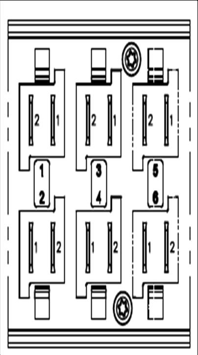
10 1.4.2 Lighting Module Wiring LIGHTING MODULE WIRING DETAIL GND LIGHTS INDICATORS VR2 INDICATORS LIGHTS GND LOOKING AT LIGHTING MODULE Connection Function Pin1 Ground Pin2 Lights Pin3 Indicators 8VR2 Controller Operation
11 VR2 Controller Operation 1.5 VR2 Locking / Unlocking The Wheelchair The VR2 control system can be locked to prevent unauthorized use. The locking method is via a sequence of key presses and joystick movements, as detailed below. To lock the wheelchair: While the control system is switched on, depress and hold the on/off button. After 1 second the control system will beep. Now release the on/off button. Deflect the joystick forwards until the control system beeps. Deflect the joystick in reverse until the control system beeps. Release the joystick, there will be a long beep. The wheelchair is now locked. To unlock the wheelchair: Use the on/off button to switch the control system on. The maximum speed / profile indicator will be rippling up and down. Deflect the joystick forwards until the control system beeps. Deflect the joystick in reverse until the control system beeps. Release the joystick, there will be a long beep. The wheelchair is now unlocked. 9 8
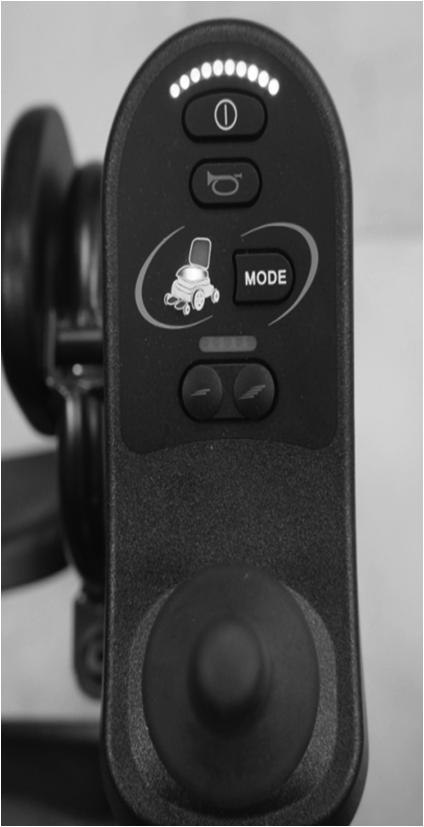
12 2.R-NET Controller Operation 2.1 Controls/JSM-LED JSM-LED JSM-LED-L Buttons/Indicator 10R-NET Controller Operation
13 Battery Gauge The battery gauge shows you that the wheelchair is switched on. It also indicates the operating status of the wheelchair. Details are given in section 3. If the battery gauge shows red, yellow and green, the batteries are charged. (LEDs 1 10) If the battery gauge shows just red and yellow, then you should charge the batteries as soon as you can. (LEDs 1 7) If the battery gauge shows just red, either steady or flashing slowly, then you should charge the batteries immediately. (LEDs 1 3) On/Off Button The On/Off button applies power to the control system electronics, which in turn supply power to the wheelchair s motors. Do not use the On/Off button to stop the wheelchair unless there is an emergency. (If you do, you may shorten the life of the wheelchair drive components). Horn Button The Horn will sound while this button is depressed. R-NET Controller Operation Maximum Speed / Profile Indicator This is a gauge which shows the maximum speed setting for the wheelchair or, if the control system is programmed for drive profile operation, the selected drive profile. This gauge also indicates if the speed of the wheelchair is being limited or if the control system is locked. Maximum Speed Indicator This is a gauge that shows the maximum speed setting of the wheelchair. There are five speed settings step 1 is the lowest speed and step 5 is the highest speed. Profile Indicator This is an indicator that shows the selected drive profile. There may be up to 5 drive profiles available, this depends on the programming of the control system. 11 2
14 Speed / Profile Decrease Button This button decreases the maximum speed setting or, if the control system is programmed for drive profile operation, selects a lower drive profile. It is possible to program the control system so this button has no effect while the wheelchair is being driven. Speed / Profile Increase Button This button increases the maximum speed setting or, if the control system is programmed for drive profile operation, selects a higher drive profile. It is possible to program the control system so this button has no effect while the wheelchair is being driven. Mode Button The Mode button allows the user to navigate through the available operating Modes for the control system. The available modes are dependent on programming and the range of auxiliary output devices connected to the control system. Actuator Indicator This LED set displays which Actuator channel is currently being controlled when the Control System is in Actuator Mode. The actuators can be programmed to work in multiple ways. Actuator selection and operation is achieved using the Joystick. Motions to the Left or Right select different actuator channels. Motions Forward and Backwards move the actuator(s) selected. 11 Hazard Warning Button and LED This button activates and de-activates the wheelchair s hazard lights. Depress the button to turn the hazards on and depress the button again to turn them off. When activated the hazard LED and the indicator LEDs will flash in sync with the wheelchair s indicators. Lights Button and LED This button activates and de-activates the wheelchair s lights. Depress the button to turn the lights on and depress the button again to turn them off. When activated the lights LED will illuminate. Left Indicator Button and LED This button activates and de-activates the wheelchair s left indicator. Depressthe button to turn the indicator on and depress the button again to turn it off. When activated the left indicator LED will flash in sync with the wheelchair s indicator(s). Right Indicator Button and LED This button activates and de-activates the wheelchair s right indicator. Depress the button to turn the indicator on and depress the button again to turn it off. When activated the right indicator LED will flash in sync with the wheelchair s indicator(s). 12R-NET Controller Operation
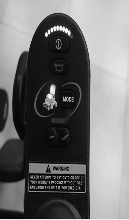
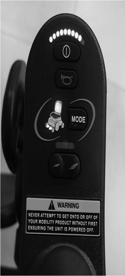
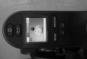
15 2.1.2 Control System Status indication The battery gauge and maximum speed /profile indicator show the status of the control system. A number of supposedly defective control systems returned to us are subsequently found to operate correctly. This indicates that many reported faults are due to wheelchair problems rather than the control system. Battery Gauge is Steady This indicates that all is well. Battery Gauge Flashes Slowly The control system is functioning correctly, but you should charge the battery as soon as possible. Battery Gauge Steps Up The wheelchair batteries are being charged. You will not be able to drive the wheelchair until the charger is disconnected and you have switched the control system off and on again. R-NET Controller Operation 13 Battery Gauge Flashes Rapidly (even with the joystick released) The control system safety circuits have operated and the control system has been prevented from moving the wheelchair. This indicates a system trip, i.e. the R-net has detected a problem somewhere in the wheelchair s electrical system. Please follow this procedure: Switch off the control system. Make sure that all connectors on the wheelchair and the control system are mated securely. Check the condition of the battery. If you can t find the problem, try using the self-help guide given in section 3.7. Switch on the control system again and try to drive the wheelchair. If the safety circuits operate again, switch off and do not try to use the wheelchair. Contact your service agent. Speed Indicator Ripples Outwards In this instance the LEDs make a ripple motion starting with the middle LED and then stepping outwards on both sides. The Control System has detected that a new module has been added and is reconfiguring. Speed Indicator LEDs 2 & 4 Flash When the control system requires a reboot; for example, after a module re-configuration, the second and fourth speed indicator LEDs will flash. Self-Help Guide If a system trip occurs, you can find out what has happened by counting the number of LEDs on the battery gauge that are flashing. 12
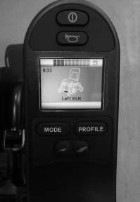
16 Below is a list of self-help actions. Try to use this list before you contact your service agent. Go to the number in the list which matches the number of flashing LEDs and follow the instructions. If the problem persists after you have made the checks described below contact your service agent. 1 LED 2 LED The battery needs charging or there is a bad connection to the battery. Check the connections to the battery. If the connections are good, try charging th e battery. The left hand motor* has a bad connection. Check the connections to the left hand motor. 3 LED The left hand motor* has a short circuit to a battery connection. Contact your service agent. 4 LED The right hand motor* has a bad connection. Check the connections to the right hand motor. 5 LED The right hand motor* has a short circuit to a battery connection. Contact your service agent. 6 LED 7 LED 8 LED The wheelchair is being prevented from driving by an external signal. The exact cause will depend on the type of whee lchair you have. A joystick fault is indicated. Make sure that the joystick is in the center position before switching on the control system. A possible control system fault is indicated. Make sure that all connections are secure. 9 LED 10 LED The parking brakes have a bad connection. Check the parking brake and motor connections. Make sure the control system connections are secure. An excessive voltage has been applied to the control system. This is usually caused by a poor battery connection. Check the battery connections. 7 7 LED + S A communication fault is indicated. Make sure that the joystick cable is securely connected and not damaged. An Actuator trip is indicated. If more than one actuator is fitted, check which actuator is not working correctly. Check th e actuator wiring. * If the programmable parameter, Motor Swap has been enabled, then left and right hand references in this table will need transposing. Slow or Sluggish Movement If the wheelchair does not travel at full speed or does not respond quickly enough, and the battery condition is good, check the maximum speed setting. If adjusting the speed setting does not remedy the problem then there may be a non-hazardous fault. Contact your service agent. Maximum Speed / Profile Indicator is Steady The display will vary slightly depending on whether the control system is programmed to operate with drive profiles. 14R-NET Controller Operation
17 Speed Indication The number of LEDs illuminated shows the maximum speed setting. For example, if the setting is speed level 4, then the four left hand LEDs will be illuminated. Profile Indication The LED illuminated shows the selected drive profile. For example, if drive profile 4 is selected, then the fourth LEDs from the left will be illuminated. Maximum Speed / Profile Indicator Ripples Up and Down This indicates the control system is locked. Maximum Speed / Profile Indicator Flashes This indicates the speed of the wheelchair is being limited for safety reasons. The exact reason will depend on the type of wheelchair, however, the most common cause is that the seat is in the elevated position R-NET Locking / Unlocking The Wheelchair R-NET Controller Operation To lock the wheelchair using the keypad; While the control system is switched on, depress and hold the On/Off button. After 1 second the control system will beep. Now release the On/Off button Deflect the joystick forwards until the control system beeps. Deflect the joystick in reverse until the control system beeps. Release the joystick, there will be a long beep. The wheelchair is now locked. The following screen will be displayed, the next time the Control System is switched on. If an LED Joystick Module is fitted the Speed Indicator LEDs will ripple from left to right. Refer To unlock the wheelchair: If the control system has switched off, press the On/Off button. Deflect the joystick forwards until the control system beeps. Deflect the joystick in reverse until the control system beeps. Release the joystick, there will be a long beep. The wheelchair is now unlocked
18 2.2 Color Joystick Modules CJSM CJSM-L 7 16R-NET Controller Operation

19 2.2.1 Buttons/Screen LCD Screen - Color This section covers those Joystick Modules that are fitted with a color LCD screen. The color LCD screen is split into 3 areas of information. The Top Bar, the Base Bar and the Main Screen Area. R-NET Controller Operation Each area is covered separately within this section. Top Bar Battery Indicator This displays the charge available in the battery and can be used to alert the user to the status of the battery. Steady: This indicates that all is well. Flashing Slowly: The control system is functioning correctly, but you should charge the battery as soon as possible. Stepping Up: The wheelchair batteries are being charged. You will not be able to drive the wheelchair until the charger is disconnected and you have switched the control system off and on again
20 Focus When the control system contains more than one method of direct control, such as a secondary Joystick Module or a Dual Attendant Module, then the Module that has control of the wheelchair will display the In Focus symbol. Base Bar Current Profile The currently selected Profile is shown in numeric form. Motor Temperature This symbol is displayed when the control system has intentionally reduced the power to the motors, in order to protect them against heat damage. Control System Temperature This symbol is displayed when the control system has intentionally reduced its own power, in order to protect itself against heat damage. 19 Main Screen Area :: Drive Screen :: Profile Name Clock This is a text string that displays the name of the currently selected Profile. The name is programmable. Refer to the programming section for details. This displays the current time in a numeric format. The clock is user adjustable. Adjustable options are: Visibility, whether the clock is displayed on screen. The display format, 12 or 24 hour. The time, the user can adjust the time. 18R-NET Controller Operation


21 Speed Display This gives a proportional display of the wheelchairs speed. The Arc begins at 0% and has a programmable maximum. Maximum Speed Indicator This displays the current maximum speed setting. Digital Speed Display This displays the actual speed of the wheelchair derived from the motors. The display can be set to mph or km/h. Latched When the control system is operating in a latched condition this symbol will be displayed. Inhibit R-NET Controller Operation :: Mode Screen :: Actuator Mode If the speed of the wheelchair is being limited; for example, by a raised seat, then this orange symbol will be displayed. If the wheelchair is being inhibited from driving, then this red symbol will be flashing. Displays the sections of the chair currently selected for movement, the name given to the selection and a direction arrow showing what sort of movement is available

22 Message Window The R-net displays warning icons and informational messages, in a dedicated message window. Restart When the control system requires a reboot; for example, after a module re-configuration, this symbol will be flashed. Timer This symbol is displayed when the control system is changing between different states. An example would be entering into Programming Mode. The symbol is animated to show the sands falling. 19 Sleep Cross & Tick This symbol will be displayed for a short time before the R-net enters into a sleep state. These symbols will be displayed during configuration procedures. Process completed correctly. Process not completed correctly. 20R-NET Controller Operation

23 E-stop If the External Profile Switch is activated during drive, or actuator operation, this symbol will be displayed. Joystick Displaced If you operate the Joystick before or just after you switch the control system on, the screen will flash the joystick displaced screen. You must release and center the Joystick to resume normal operation. If you do not release the Joystick within five seconds the wheelchair will not be able to move, even if you release the Joystick and operate it again. The screen will display a diagnostic screen at this time. You can reset this condition by switching the control system off and on again. Control System Locked Diagnostic Screen The Control System can be locked in one of two ways. Either using a sequence of deflections and presses with a Joystick or with a physical Key. How the Control System is locked depends on how the wheelchair manufacturer has programmed it. R-NET Controller Operation When the control system safety circuits have operated and the control system has been prevented from moving the wheelchair a diagnostics screen will be displayed. This indicates a system trip, i.e. the R-net has detected a problem somewhere in the wheelchair s electrical system Settings Menu The Settings Menu allows the user to adjust the CJSM display in terms of clock adjustment and display format, the brightness of the backlight, the background color and the behavior of the odometer. The menu is accessed by depressing the Speed Down and Speed Up buttons simultaneously. A typical Settings Menu display would be as below. Each of the menu items are described in the following sections

24 Set Time A right joystick deflection will enter a clock adjustment screen in which further joystick deflections are used to set the time. Display Time This sets the format of the time display or turns it off. The options are 12hr, 24hr or Off. Left and right joystick deflections are used to change between the options. Distance This sets the functionality of the odometer and a screen as below will appear. Total Distance Trip Distance Display Distance Clear Trip Distance Exit This is a value held in the Power Module and relates to the total distance driven using that Power Module. This is a value held in the CJSM and relates to the total distance driven since the last reset. Sets whether Total Distance or Trip Distance appears as the odometer display on the CJSM. A right joystick deflection will clear the Trip Distance value. A right joystick deflection will return to the Settings Menu. 21 Backlight This sets the intensity of the LCD backlight. The adjustable range is 0% to 100% in steps of 10%. Adjustments are made with left and right joystick deflections. Background This sets the color of the screen background. Blue is the standard, but in very bright sunlight then a white background will make the display more visible. The options are Blue, White and Auto. Left and right joystick deflections are used to change between the options. Blue means the background will be blue in all Profiles. White means the background will be white in all Profiles. Auto means the color will be set by the programmable parameter, Background, which can be set to be different across the Profiles. For example, blue for the slower Profiles that are for indoor use and white for the faster Profiles intended for outdoor use. For more details of the parameter, Background, refer to the relevant section in the Programming chapter. Exit Exits the Settings Menu back to normal operation. 22R-NET Controller Operation
25 2.3 Module Wiring Power Module Wiring The following diagram gives details of the LED Power Module connections R-NET Controller Operation 23 22

26 2.3.2 ISM Wiring The following diagram gives details o the ISM connections Model: ISM-X-L X=4, Actuator channels 1~4 Axis 6, Actuator channels 1~6 Axis L=Lights Function 23 24R-NET Controller Operation

27
28
29 R-NET Controller Operation 27 26

30 27 28R-NET Controller Operation
31 3. Charger Connector An Off-Board Charger can be connected to the Joystick Module s charger connector. The charger connector is Neutrik 3 pin type NC3FPP or equivalent, and the maximum charging current is 12A rms. Only chargers fitted with Neutrik NC3MX plugs should be connected into the Joystick Module. The pin connections of the charging socket are as below. Pin Connection 1 Battery Positive 2 Battery Negative 3 Inhibit Charger Connector 29 28
32 Rev /04/2015
PG DRIVES TECHNOLOGY R-NET- TECHNICAL MANUAL SK77981/12
 PG DRIVES TECHNOLOGY R-NET- TECHNICAL MANUAL SK77981/12 Curtiss-Wright 2015 All rights reserved. This manual is furnished under copyright and may only be used in accordance with the terms laid out by Curtiss-Wright.
PG DRIVES TECHNOLOGY R-NET CJSM2 TECHNICAL MANUAL SK
 PG DRIVES TECHNOLOGY R-NET CJSM2 TECHNICAL MANUAL SK81302-03 Curtiss-Wright 2016 All rights reserved. This manual is furnished under copyright and may only be used in accordance with the terms laid out
SUNRISE MEDICAL EDUCATION DEPARTMENT INFO. VR2 Codes Display and Code description
 VR2 Codes Display and Code description NOTE: A Complete Description Taken from the official PG Drives Engineering Manual is described on the next 3 pages TRIP CODE Details from Page listing Trip Code 1-1
PG DRIVES TECHNOLOGY R-NET- TECHNICAL MANUAL SK77981/14
 PG DRIVES TECHNOLOGY R-NET- TECHNICAL MANUAL SK77981/14 Curtiss-Wright 2016 All rights reserved. This manual is furnished under copyright and may only be used in accordance with the terms laid out by Curtiss
PP1a Programmer Pilot, Pilot+ and VSI Control Systems PROGRAMMING AND DIAGNOSTICS SK73747/ Penny & Giles Drives Technology Ltd.
 PP1a Programmer Pilot, Pilot+ and VSI Control Systems PROGRAMMING AND DIAGNOSTICS SK73747/7 2001 Penny & Giles Drives Technology Ltd. PENNY+GILES DRIVES TECHNOLOGY CONTENTS CONTENTS CONTENTS...iii Chapter...
Basic Operation Instructions
 Basic Operation Instructions 4 Identification Key 4 3 2 1 6 5 7 8 Copyright 2016 INFMANU3354/Rev G/December 2016 Identification Key 3 1 2 Controller Battery Condition Meter On/Off Button 3 4 5 Horn Button
USER MANUAL CONTROLS VR2 (PG DT)
") USER MANUAL CONTROLS VR2 (PG DT) EN 2 VR2 VR2 3 English 2014 Handicare All rights reserved. The information provided herein may not be reproduced and/or published in any form, by print, photoprint, microfilm
USER MANUAL CONTROLS VR2 (PG DT) EN 2 VR2 VR2 3 English 2014 Handicare All rights reserved. The information provided herein may not be reproduced and/or published in any form, by print, photoprint, microfilm
medemagroup Joystick DX2 User guide P Q ver October 2011
 medemagroup P9-0290-Q ver. 1.0.2 - October 2011 GB User guide Joystick DX2 Quick guide P9-0290-Q 2 of 16 Version 1.0.2/2011 Contents Introduction...4 Joystick parts...5 Operating...5 Clock on/off...6 Set
PG DRIVES TECHNOLOG OMNI+ SPECIALTY CONTROLS MODULE OPERATION & INSTALLATION SK75002/7
 PG DRIVES TECHNOLOG OGY OMNI+ SPECIALTY CONTROLS MODULE OPERATION & INSTALLATION OMNI+ MODULE PG DRIVES TECHNOLOGY PG Drives Technology 2002 All rights reserved. This manual is furnished under copyright
INSTALLATION AND OPERATING INSTRUCTIONS DSST SYSTEM
 INSTALLATION AND OPERATING INSTRUCTIONS DSST SYSTEM PROPORTIONAL and NON-PROPORTIONAL TOGGLE SWITCH RADIO REMOTE CONTROL SYSTEM MODEL FHSTP/DSSTP SERIES FHST/DSST SYSTEM DESCRIPTION The DSST Wireless Control
II. Programming and Adjustments
 - 35 - Dip es i) Dip for the M-17/27 combination relay box Dip switches are located inside most control boxes and are used to set, enable, or disable various electronic functions operated through the control
Quickie HHP Programming Tree
 Program Operate Monitor Motor Controller General Creep DP Drive profiles System Actuators* Veer Comp Fwd Veer Comp Rev Latch speed step Soft stop Brake Parameters Enable encoders Dir Act SW1 Dir Act SW2
DX Dolphin Remote (DX-Rem34) Installation Manual
 Installation Manual") TM DX Dolphin Remote (DX-Rem34) Installation Manual Order/Part Number for this Manual : GBK60025 issue 5 Important Notes 1. Read this Manual carefully before installing or operating your DX control system.
TM DX Dolphin Remote (DX-Rem34) Installation Manual Order/Part Number for this Manual : GBK60025 issue 5 Important Notes 1. Read this Manual carefully before installing or operating your DX control system.
ADVANTAGE DKE QUICK START GUIDE. 2 Make sure you have everything shown here. 3. What s what? All important internal components labeled for you
 1 of 6 START HERE 1 Carefully unpack box. 2 Make sure you have everything shown here. 3 Unlock and remove front panel of keypad unit, then using carriage bolts and hex nuts, attach unit to pedestal as
Remote Plus Controller
 Synergy TRU-Balance Po BASIC OPERATION INSTRUCTIONS TM Remote Plus Controller ACN# 088 609 661 ACN# 088 609 661 INFORMATION LABELING 2 Basic Operation Instructions The symbols below are used throughout
Invacare LiNX. User Manual. DLX-REM110, DLX-REM211, DLX-REM216, Supplement to power wheelchair user manual
 Invacare LiNX DLX-REM110, DLX-REM211, DLX-REM216, Supplement to power wheelchair user manual en Remote User Manual This manual MUST be given to the user of the product. BEFORE using this product, read
Manual enable 40. Powerchair Control System. Curtis Instruments, Inc. 200 Kisco Avenue Mt. Kisco, NY
 Manual enable 40 Powerchair Control System Curtis Instruments, Inc. 200 Kisco Avenue Mt. Kisco, NY 10549 www.curtisinstruments.com Read Instructions Carefully! Specifications are subject to change without
VERMEIREN. DX2 Basic: without LCDscreen DX2 with LCD screen
 VERMEIREN DX2 Basic: without LCDscreen DX2 with LCD screen I N S T R U C T I O N M A N U A L OPERATOR CONTROL DX2 1. Use The operator control built into your electric wheelchair enables you to control
advanced joystick remote
 advanced joystick remote THE UTIMATE POWECHAI CONTO SOUTION DX2-EM550/EM551 From software v2.03 onwards QUICK STAT GUIDE GBK65480: Issue 2 This quick start guide does not replace the full installation
M A C 3 Wind Speed Alarm & Controller
 M A C 3 Wind Speed Alarm & Controller Installation Instructions Thank you for purchasing the MAC3 wind speed alarm and controller. This manual is designed to lead you through a step-by-step process to
Instructions for Use Mini-Config. Error Codes for Safe Gate Panel
 Instructions for Use Mini-Config Error Codes for Safe Gate Panel US How to contact Permobil Head Office of the Permobil group Produced and published by Permobil AB, Sweden Edition no.6, 2- Article no.:
D115 The Fast Optimal Servo Amplifier For Brush, Brushless, Voice Coil Servo Motors
 D115 The Fast Optimal Servo Amplifier For Brush, Brushless, Voice Coil Servo Motors Ron Boe 5/15/2014 This user guide details the servo drives capabilities and physical interfaces. Users will be able to
InControl INCONTROL OVERVIEW
 INCONTROL OVERVIEW InControl uses smartphone and in-vehicle mobile technology, to remotely connect the vehicle to a number of services and convenience features. Note: For further information, access the
4 Leg Air +Hydraulic Leveling System
 4 Leg Air +Hydraulic Leveling System Setup & Configuration Guide Operation Guide Air/Hydraulic FIRMWARE VERSIONS: CONTROLLER 2.18 FRONT SENSOR 2.6 REAR SENSOR 2.9 PNEUMATIC I/O MODULE 2.4 FIRMWARE VERSIONS:
Invacare. LiNX Control System. Smart Technology: Redefining Mobility
 Invacare LiNX Control System Smart Technology: Redefining Mobility Invacare LiNX Invacare LiNX is our insight inspired control system with advanced technology that provides a superb driving experience
e-ask electronic Access Security Keyless-entry OEM / Dealer / Installer Cargo Lock / Unlock Version Installation & Instructions (UM04 ~ )
") e-ask electronic Access Security Keyless-entry OEM / Dealer / Installer Cargo Lock / Unlock Version Installation & Instructions (UM04 ~ 18990-04) Table of Contents Introduction... 1 e-fob Operation and
e-ask electronic Access Security Keyless-entry OEM / Dealer / Installer Cargo Lock / Unlock Version Installation & Instructions (UM04 ~ 18990-04) Table of Contents Introduction... 1 e-fob Operation and
MEGA DIAL PANEL Instructions
 2036 Fillmore Street Davenport, Ia. 52804 563-324-1046 www.racedigitaldelay.com MEGA DIAL PANEL Instructions WARRANTY AND DISCLAIMER DIGITAL DELAY ELECTRONICS INC. WARRANTS THE PRODUCTS IT MANUFACTURES
What s in the Box? REAR VIEW SAFETY
 TM 1 What s in the Box? 1 Full HD Color Infra-red Weather Proof Camera 1 Full HD 7" TFT LCD Color Monitor w/monitor Mount 1 Power Harness 1 66 Camera Cable 1 Power Connection Wire 1 Screw Kit for installation
HCS-3600 / 3602 / 3604 Laboratory Grade & High RFI Immunity Switching Mode Power Supply with Rotary Encoder Control
 HCS-3600 / 3602 / 3604 Laboratory Grade & High RFI Immunity Switching Mode Power Supply with Rotary Encoder Control 1. INTRODUCTION User Manual This family of efficient, upgraded SMPS with small form factor,
用户手册. KT-LCD6 ebike Special Meter
 用户手册 User Manual KT-LCD6 ebike Special Meter WWW.SZKTDZ.COM Contents Preface... 4 Outlook and Size... 4 Meter Dimension 4 Button Box Dimension.. 4 Main Material and Color.... 5 Wiring Schematic.. 5 Installation
Invacare LiNX. User Manual. DLX-REM400, Supplement to power wheelchair user manual
 Invacare LiNX DLX-REM400, Supplement to power wheelchair user manual en Remote User Manual This manual MUST be given to the user of the product. BEFORE using this product, this manual MUST be read and
ColorLogic 4.0 Installation Guide
 ColorLogic 4.0 Installation Guide Copyright 2011 Hayward Industries Table of Contents Safety Precautions Page 1 Overview Page 2 Program Table Page 3 Network Module Installation Page 4 Wiring Lights Pages
Manual. C500B LCD Instructions
 Manual C500B LCD Instructions CONTENT ABOUT THE USER MANUAL 3 OUTLOOK AND SIZE 3 MATERIAL AND COLOR 3 BUTTON DEFINITION 4 FUNCTION SUMMARY 5 FULL VIEW AREA 7 NORMAL VIEW AREA 7 NORMAL OPERATION 8 1.ON/OFF
MAC3 Wind Speed Alarm & Controller. Installation Instructions
 MAC3 Wind Speed Alarm & Controller Installation Instructions Table of Contents Overview... 3 Installation... 3 Optional Equipment... 10 Dual Sensor Operation... 10 Other Optional Equipment... 10 Operation
Troubleshooting Guide
 Platinum Lift Power Recliner with 6-Motor Massage & Heat WARNING To reduce the risk of injury: Do not attempt to disassemble or service the actuators. No serviceable parts are inside. Introduction: This
ODES Zeus Touch Owner s Manual
 ODES Zeus Touch 2017 Owner s Manual 2016-09-15 1611997 We continually strive to bring you the highest quality, full-featured products. As a result, you may find that your actual display screens may be
2000 Series e/em Style Keypad Installation and Programming Manual
 2000 Series e/em Style Keypad Installation and Programming Manual Document Number: 6054022 Revision: 0 Date: 12/21/06 Table of Contents Table of Contents Section 1: Introduction... 6 1 Product Description...6
POCKET PRO HL400-C CIRCUIT
 POCKET PRO HL400-C CIRCUIT User Manual Version 09/2015 TAGHeuer Timing Page 1 / 20 Contents Table 1. Concept 3 2. Standard Timing Mode 4 2.1. LCD description 4 2.2. General 4 2.2.1. How to navigate the
CF3000 Dealer Diagnostic Tool Instruction Manual
 CF3000 Dealer Diagnostic Tool Instruction Manual Table of Contents: About the CF3000......3 Important Precautions......4 Components....5 Charging the CF3000......7 Licensing the CF3000.......8 Updating
用户手册. User Manual. S-LCD8 ebike Special Meter
 用户手册 User Manual S-LCD8 ebike Special Meter WWW.BMSBATTERY.COM Contents Preface... 4 Outlook and Size... 4 Meter Dimension 4 Button Box Dimension..5 Main Material and Color.... 5 Wiring Schematic.. 5 Installation
Installation and Operation Back-UPS BR1000G-IN / BR1500G-IN
 Installation and Operation Back-UPS BR1000G-IN / BR1500G-IN Important Safety Information Read the instructions carefully to become familiar with the equipment before trying to install, operate, service
Service and Maintenance for Powerchairs Technical Manual R-net
 Service and Maintenance for Powerchairs Technical Manual R-net 1 TM_R-net_EN_EU_rev1.0_03_08_09 PRODUCT INFORMATION Scope This Technical Manual has been designed to help you install and configure the
POCKET PRO HL400-C CIRCUIT. User Manual. Version 08/2014
 POCKET PRO HL400-C CIRCUIT User Manual Version 08/2014 TAG Heuer Timing Page 1 Contents Table 1. Concept 3 2. Standard Timing Mode 4 2.1. LCD description 4 2.2. General 4 2.2.1. How to navigate the different
Custom Programmer PP1c. Owner s Manual
 Custom Programmer PP1c Owner s Manual US How to contact Permobil Head Office of the Permobil group Custom Programmer PP1c Owner s Manual Produced and published by Permobil AB, Sweden Edition no. 2, 22-12
791/793 Easy Entry Keypads
 791/793 Easy Entry Keypads Description The DMP 791 and 793 Easy Entry LCD Keypads are the industry s first burglary/fire keypads with integrated access control capability. Each keypad provides three 2-button
User Guide for the Mobius Mini ActionCam
 Instruction Manual Mobius Min... 1 User Guide for the Mobius Mini ActionCam Description The above picture shows the arrangement of the user operating features. This manual does not cover replacing the
POCKET PRO HL400-R RALLY
 POCKET PRO HL400-R RALLY User Manual Version 09/2015 TAGHeuer Timing Page 1 / 24 Contents Table 1. Concept 3 2. Standard Timing Mode 4 2.1. LCD description 4 2.2. General 4 2.2.1. How to navigate the different
Copyright 2013 DOD Tech All Rights Reserved
 LS430W USER MANUAL Copyright 2013 DOD Tech All Rights Reserved Content IMPORTANT SAFETY INSTRUCTION...2 PACKAGE CONTENTS...3 CONTROLS AND FUNCTIONS...4 INSTALLATION AND CONNECTION...6 GETTING START...7
Moomba Boats PV480 Color Display
 Moomba Boats PV480 Color Display 2018 Owner s Manual 1715055 2017-08-30 We continually strive to bring you the highest quality, full-featured products. As a result, you may find that your actual display
Operating Manual. for HXOC Page 1 of 5
 Operating Manual for HXOC-003-000-02 Page 1 of 5 ESM PROGRAMMER: OPERATING MANUAL This handheld programming device is designed for setting the two selectable operating speeds available on the ebm-papst
KP2000E/EM Series Style Keypad
 23852973 KP2000E/EM Series Style Keypad Installation and Programming Instructions Models KP2000EXX and KP2000EMXX Specifications Parameter Voltage Requirements Keypad Current Requirements (Max) Relay Contact
LiNX Access PC Programming and diagnostic tool
 LiNX Access PC Programming and diagnostic tool LiNX Access PC User Manual GBK54033 Issue 4 June 2017 Page left blank intentionally 1 Welcome 1.1 Introduction 2 1.2 Using this manual 2 1.3 Important information
Wiring Instructions v3
 Wiring Instructions v3 Gatekeeper h4.1 Technical Support support@gymmastersoftware.com USA: 415 678 1270 Australia: 03 9111 0323 : 03 974 9169 Copyright 2017 Treshna Enterprises. All rights reserved. Table
GALACTIC MOON 2CE. user manual. Abstract Design to Light 1996 Tel:
 GALACTIC MOON 2CE user manual Abstract Design to Light 1996 Tel:0116 278 8078 Galactic Moon 2CE Instruction Manual - Issue 1.1: Jan 96 (software v1.1) Written for Abstract Design to Light by Tim Mitchell,
OFFICE UPS MULTI-DEVICE PROTECTION UPS 500S/600S/750S
 OFFICE UPS MULTI-DEVICE PROTECTION UPS 500S/600S/750S USER S MANUAL 1.Safety instructions Thank you for selecting this uninterrupted power source. It provides you with better protection for connected equipment.
QCPort Cover Control Trouble Shooting Guide
 QCPort Cover Control Trouble Shooting Guide Technical Document Feb. 2006 Page 1 of 14 QCPort Cover Control Description Door Defeater Address/Options Bucket Latch Breaker Actuator Hasp Lock Keypad Overlay
VR2 Programming Settings - Sunrise Education & Training
 VR2 Programming Settings - Sunrise Education & Training The Programmer Face Acceleration? Adjusts the value for forward acceleration of the wheelchair, in increments of 1. The higher the value the faster
R-net Error Code List
 Text displayed on Name Extended Description Fault Type JSMorOMNI 0001 Memory Running Ram Check 0200 PM Memory EEPROM Check System fault PM Memory 2 0203 Calibration EEPROM Calibration Data Check System
Invacare LiNX. User Manual. DLX-REM110, DLX-REM211, DLX-REM216, Supplement to power wheelchair user manual
 Invacare LiNX DLX-REM110, DLX-REM211, DLX-REM216, Supplement to power wheelchair user manual en Remote User Manual This manual MUST be given to the user of the product. BEFORE using this product, read
Trouble Shooting Leveling Control Box Electric Jacks. Touch Pad LED Probable Cause Solution
 Trouble Shooting Leveling Control Box 140-1224 Electric Jacks Copyright Power Gear Issued: January 2013 #82-L0524, Rev. OA Touch Pad LED Probable Cause Solution 1. On/Off LED will not light 2. Wait LED
INSTALLATION SHEET 791 and 793 Easy Entry Keypads
 INSTALLATION SHEET 791 and 793 Easy Entry Keypads Description The DMP 791 and 793 Easy Entry LCD Keypads are the industry s first burglary/fire keypads with integrated access control capability. Each keypad
TARA CONTROLS AGC-5. UCI Random Start USER S GUIDE. With Optional Warning Flashes for the Hearing Impaired. TARA CONTROLS by Cartessa Corporation
 TARA CONTROLS AGC-5 UCI Random Start USER S GUIDE With Optional Warning Flashes for the Hearing Impaired TARA CONTROLS by Cartessa Corporation 4825 Cincinnati-Brookville Road Shandon, Ohio 45063 Phone:
CAM-KIT6. User Manual. Connects2Vision. Mirror with DVR & Rear Camera PRODUCT FEATURES:
 User Manual CAM-KIT6 Mirror with DVR & Rear Camera PRODUCT FEATURES: Display: 5 inch Speaker: Built in MIC: Built in Mini USB: 5V 2A Micro SD Card Support: 32G max (not supplied) Rear Camera Input: 2.5mm
Ostar Eye K6. Beam and Kaleido Effects. User manual. Please read the instructions carefully before use
 Ostar Eye K6 Beam and Kaleido Effects User manual Please read the instructions carefully before use TABLE OF CONTENTS 1. Safety Instructions... 2 2. Technical Specifications... 4 3. How To Control The
OWNER S & INSTALLATION LATIO GUIDE
 OWNER S & INSTALLATION LATIO GUIDE THIS IS A TEMPORARY COVER THE FINAL COVER IS IN A SEPARATE FILE TOUCH SCREEN COLOR 2-WAY UPGRADE KIT 20 THIS IS A TEMPORARY COVER THE FINAL COVER IS IN A SEPARATE FILE
广州谐同电子科技有限公司 Guangzhou Electrony Corporation 用户手册. User Manual. S-LCD3 ebike Special Meter
 广州谐同电子科技有限公司 Guangzhou Electrony Corporation 用户手册 User Manual S-LCD3 ebike Special Meter WWW.ELECTRONY.CN Contents Preface... 4 Outlook and Size... 4 MeterDimension 4 Button Box Dimension.. 4 Main Material
用户手册. User Manual. KT-LCD5 ebike Special Meter
 用户手册 User Manual KT-LCD5 ebike Special Meter WWW.SZKTDZ.COM Contents Preface... 3 Outlook and Size.. 3 Meter Dimension 3 Main Material and Color....... 3 Wiring Schematic. 3 Installation Instruction..
IMPORTANT SAFETY INSTRUCTIONS SAVE THESE INSTRUCTIONS
 IMPORTANT SAFETY INSTRUCTIONS IMPORTANT SAFETY INSTRUCTIONS SAVE THESE INSTRUCTIONS WARNING (SAVE THESE INSTRUCTIONS): This manual contains important instructions that should be followed during installation
FACTORY. Digital Controller Instructions. Version 302
 FACTORY Digital Controller Instructions Version 302 Geo Knight & Co Inc 52 Perkins St, Brockton MA 02302 USA (508)588-0186 - Fax (508) 587-5108 info@heatpress.com - www.heatpress.com 1 Contents Voltage
C500B-LCD Instructions
 C500B-LCD Instructions Nanjing Bigstone Electronic & Technology co.,ltd CONTENT ABOUT THE USER MANUAL........ 3 OUTLOOK AND SIZE........ 3 MATERIAL AND COLOR 3 BUTTON DEFINITION..... 4 FUNCTION SUMMARY....
Qtronix Programmer - [Present Unit]
![Qtronix Programmer - [Present Unit]](/thumbs/86/93502642.jpg "Qtronix Programmer - [Present Unit]") Qtronix Programmer - [Present Unit] 4 Main Key Features HELP KEY [?] : Describes function of menu item. UP/YES KEY: Scrolls up through menu. Increases a setting. Changes no to yes. DOWN/NO KEY: Scrolls
Qtronix Programmer - [Present Unit] 4 Main Key Features HELP KEY [?] : Describes function of menu item. UP/YES KEY: Scrolls up through menu. Increases a setting. Changes no to yes. DOWN/NO KEY: Scrolls
from P.R.Engineering Ltd Tel:
 Quick Start FRE-205 INSTRUCTIONS from P.R.Engineering Ltd www.laser-level.co.uk Tel: 01246 269 777 Thank you for purchasing the FRE-205 Auto Rotary laser level kit. These instructions are intended to explain
simple joystick remote
 simple joystick remote THE ULTIMATE POWERCHAIR CONTROL SOLUTION DX2-REM420/REM421 INSTALLATION MANUAL About this Manual This manual can help you understand and install the Dynamic DX2-REM420/421. It describes
Integriti User Manual. Elite / EliteX LCD Terminal Keypads
 Integriti User Manual Elite / EliteX LCD Terminal Keypads INNER RANGE recommends that all INTEGRITI systems are installed & maintained by FACTORY CERTIFIED TECHNICIANS. For a list of Accredited Dealers
Installation and Operation Back-UPS Pro 900
 Us er Documentation Installation and Operation Back-UPS Pro 900 Inventory bu001a User Documentation (2) Safety and General Information Inspect the package contents upon receipt. Notify the carrier and
DX Dolphin Tray Remote (DX-Rem41) Installation Manual
 Installation Manual") TM DX Dolphin Tray Remote (DX-Rem41) Installation Manual Order/Part Number for this Manual : GBK60069, issue 1. Important Notes 1. Read this Manual carefully before installing or operating your DX control
TM DX Dolphin Tray Remote (DX-Rem41) Installation Manual Order/Part Number for this Manual : GBK60069, issue 1. Important Notes 1. Read this Manual carefully before installing or operating your DX control
TC200 Operation & Installation Guide. Revision 1.0
 TC200 Operation & Installation Guide Revision 1.0 2006 2007 Monit Limited. Product of New Zealand. Introduction Thank you for your purchase of this rally computer product. At monit, we take pride in everything
METERING/DISPLAY MANUAL
 METERING/DISPLAY MANUAL 175W - 750W SINGLE PHASE Series LV EMERGENCY LIGHTING CENTRAL INVERTER Myers Power Products, Inc. 44 South Commerce Way, Bethlehem, PA 18017 1-800-526-5088 (610) 868-3500 Fax: (610)
POCKET PRO HL400-W WINTER
 POCKET PRO HL400-W WINTER User Manual Version 09/2014 TAGHeuer Timing Page 1 / 20 Contents Table 1. Concept 3 2. Standard Timing Mode 4 2.1. LCD description 4 2.2. General 5 2.2.1. How to navigate the
Abstract. GLV User Manual 1
 GLV User Manual 1 Abstract This user manual is a high level document that explains all operational procedures and techniques needed to operate the GLV system in a safe and effective manner. Anyone operating
Specifications N Termination Voltage Range Current Consumption, Max. Type Number Termination. Voltage Range. Sinking Sensor Current
 Description The N24 Controller is a specialized Motorized Roller Driver Module for NorthAmCon Mech-Rollers. It includes the following features: 6 PNP Auxiliary I/O points to provide enhanced diagnostic
smartentry Wireless Video Doorphone User Manual
 smartentry Wireless Video Doorphone User Manual Designed & Engineered Version 1.2 in the United Kingdom Contents Precautions... 3 1. Product Overview... 4 1.1. Product Features... 4 1.2. Contents... 4
Table of content 1 Preface 18 2 Appearance and size Material and color Display size and installation size 19 3 Function summary and
 Table of content 1 Preface 18 2 Appearance and size.19 2.1 Material and color 19 2.2 Display size and installation size 19 3 Function summary and button definition 20 3.1 Preset and default items. 20 3.2
PROCKET PRO HL400-S SWIMMING
 PROCKET PRO HL400-S SWIMMING User Manual Version 09/2015 TAGHeuer Timing Page 1 / 24 Contents Table 1. Concept 3 2. Standard Timing Mode 4 2.1. LCD description 4 2.2. General 4 2.2.1. How to navigate the
Ostar Eye K18. Beam and Kaleido Effects. User manual. 6. Fixture Cleaning. Please read the instructions carefully before use
 6. Fixture Cleaning The cleaning of internal and external optical lenses and/or mirrors must be carried out periodically to optimize light output. Cleaning frequency depends on the Ostar Eye K18 Beam and
VEX ARM Cortex -based Microcontroller and VEXnet Joystick User Guide
 1. VEX ARM Cortex -based Microcontroller and VEXnet Joystick Pairing Procedure: a. The Joystick must first be paired to the VEX ARM Cortex -based Microcontroller before they will work using VEXnet Keys.
REMOTE METER USER MANUAL KAMPPTRC
 REMOTE METER USER MANUAL K A M P P T R C KAMPPTRC 1. PRODUCT FEATURES 1) LCD screen. 2) Can display up to 10 parameters and states. 3) Has a low power consumption with BLE4.0 feature for strong communication
Installation Instructions
 Please read all instructions before installing SPECIFICATIONS RT-100 Time Switch Programmable Countdown Voltage...120VAC, 60HZ Load (Single Pole Circuit) Incandescent or fluorescent lamp... 0 600 Watt
SPOT MOVING HEAD M1S150W USER MANUAL. For safety, please read this user manual carefully before initial use.
 SPOT MOVING HEAD M1S150W USER MANUAL For safety, please read this user manual carefully before initial use. Event Lighting reserves the right to revise the manual at any time. Information and specifications
5.6" Multi-function Monitor
 5.6" Multi-function Monitor User s Manual Please read this Manual carefully before use of this product, and keep it handy for future reference. I. Packing List.. 2 II. Product Appearance... 3-5 III. Product
Roof Truss Roller Press, Tables and Jigging
 RoofTracker II Roof Truss Roller Press, Tables and Jigging August 2015 Page 1 Table of Contents Equipment Introduction to the Equipment Restricted Zone Truss Terminology Parts of a Truss Important Notes
ELECTRIC BICYCLE METER KT LCD3 Product User Manual. Contents
 Contents Preface... 4 Outlook and Size... 4 MeterDimension 4 Button Box Dimension.. 4 Main Material and Color.... 5 Wiring Schematic.. 5 Installation Instruction... 5 Φ 31.8 handlebar diameters install
Series F75 Fail-Safe Module Installation, Operation and Maintenance Instructions
 WCAIM2029 (Part 16022) Series F75 Fail-Safe Module Installation, Operation and Maintenance Instructions CAUTION: Flowserve recommends that all products that must be stored prior to installation be stored
FIRING SYSTEMS 270 Old Dublin Rd PETERBOROUGH N.H PHONE FAX
 FIRING SYSTEMS 270 Old Dublin Rd PETERBOROUGH N.H. 03458 PHONE 603-924-4251 FAX 603-924-6748 www.pyromate.com pyromate@monad.net Firmware Version 2.02 Page 1 of 19 Table of Contents Features of the Night
OMRON PROGRAMMABLE CONTROLLER. Input terminals TIMER ADJUSTMENT
 PLC004 21/01/04 DISPLAY UNIT MANUAL 1 OMRON PROGRAMMABLE CONTROLLER Input terminals Input indication LED s Programming port OMRON SYSMAC CPM2A Expansion connector Potentiometers located behind peripheral
What you get Welcome to the best generation of keyless entry with remote start. Your system contains everything you need.
 A U X Congratulations Congratulations on the purchase of your state-of-the-art remote start and keyless entry system. Reading this Owner s Guide prior to using your system will help maximize the use of
MSD Programmable Launch RPM Controller
 MSD Programmable Launch RPM Controller PN 75611 Parts Supplied 1 - Programmable Launch Rev Limiter, PN 75611 4 - Self Tapping Screws 1 MSD Pro-Data+ Software 3.5 Disk 1 Deutsch Harness 1 9-Pin Computer
Quick Start Guide TS A
 Quick Start Guide TS 930 125-630A DANGER HAZARD OF ELECTRICAL SHOCK, EXPLOSION, OR ARC FLASH Read and understand this quick start guide before installing and operating the transfer switch The installer
EVERSAN. MODEL 9658 EVERSAN PERIOD INDOOR/OUTDOOR MULTI-FUNCTION SCOREBOARD. Instruction Manual
 MODEL 9658 EVERSAN HOME PERIOD POSS. POSS. BONUS BONUS GUEST INDOOR/OUTDOOR MULTI-FUNCTION SCOREBOARD Instruction Manual Address: 34 Main Street, Whitesboro, NY 13492 Phone: 315-736-3967 Toll Free: 800-383-6060
User Manual V K Camera with an Integrated 3-axis Gimbal
 User Manual V 1.1 4K Camera with an Integrated 3-axis Gimbal Table of Contents Introduction 3 At a Glance 3 Charging the Battery 4 Status Battery LED Indicator Description 4 Check the Battery Level 5 Insert