1. LCD (Liquid Crystal Display)interface
|
|
|
- Lucinda Armstrong
- 6 years ago
- Views:
Transcription

1 e-pg Pathshala Subject : Computer Science Paper: Embedded System Module: I/O devices Interfacing Module No: CS/ES/16 Quadrant 1 e-text In this lecture, the interfacing of 8051 with an output device and an input device are described. The output device considered is LCD display, and the input device is a matrix-type keyboard. The operation modes of LCD are first discussed. Interfacing of the LCD to an 8051 microcontroller using Assembly and C is also discussed. This is followed by the keyboard interface details. 1. LCD (Liquid Crystal Display)interface LCDs can display numbers, characters, and graphics. To produce a proper display, the information has to be periodically refreshed. This can be done by the CPU or internally by the LCD device itself. Incorporating a refreshing controller into the LCD, relieves the CPU of this task and hence many LCDs have built-in controllers. These controllers also facilitate flexible programming for characters and graphics. Figure 1.1 shows the pin description of an LCD from Optrex. Figure 1.1 Pin Descriptions of LCD Vss and VDD provide +5v and ground, V0 is used for controlling LCD contrast. If RS=0, the instruction command register is selected, allowing the user to send a command such as clear display, cursor at home, etc. If RS=1 the data register is selected, allowing the user to send data to be displayed on the LCD. R/W input allows the user to Read/ Write the information to the LCD. The enable pin is used by the LCD to latch information presented to its data pins. The 8-bit data pins are used to send information to LCD. Section 1.1 discusses about command codes for writing the instructions on the LCD register.

2 Section 1.2 gives an example program for displaying a character on the LCD. Section 1.3 shows the communication of LCD with a busy flag and section 1.4 gives a detailed explanation of LCD data sheet. 1.1 LCD Command Codes The LCD s internal controller can accept several commands and modify the display accordingly. These commands would be things like: Clear screen Return home Decrement/Increment cursor After writing to the LCD, it takes some time for it to complete its internal operations. During this time, it will not accept any new commands or data. Figure 1.2 shows the command codes of LCD and Figure 1.3 shows the LCD interfacing. We need to insert a time delay between any two commands or data sent to LCD. A long delay has to be given between issuing data or commands to the LCD. Figure 1.2: Command codes of LCD

3 1.2 Program to Display characters on LCD Figure 1.3 LCD Interfacing To send any of the commands to the LCD, make pin RS=0. For data, make RS=1. Then send a high-to-low pulse to the E pin to enable the internal latch of the LCD. This is shown in the code below. ;calls a time delay before sending next data/command ;P1.0-P1.7 are connected to LCD data pins D0-D7 ;P2.0 is connected to RS pin of LCD ;P2.1 is connected to R/W pin of LCD ;P2.2 is connected to E pin of LCD ORG 0H MOV A,#38H ACALL COMNWRT ACALL DELAY MOV A,#0EH ACALL COMNWRT ACALL DELAY MOV A,#01 ACALL COMNWRT ACALL DELAY ;INIT. LCD 2 LINES, 5X7 MATRIX ;call command subroutine ;give LCD some time ;display on, cursor on ;call command subroutine ;give LCD some time ;clear LCD ;call command subroutine ;give LCD some time
4 MOV A,#06H ACALL COMNWRT ACALL DELAY ;shift cursor right ;call command subroutine ;give LCD some time MOV A,#84H ;cursor at line 1, pos. 4 ACALL COMNWRT ACALL DELAY MOV A,# N ACALL DATAWRT ACALL DELAY MOV A,# O ACALL DATAWRT ;call command subroutine ;give LCD some time ;display letter N ;call display subroutine ;give LCD some time ;display letter O ;call display subroutine AGAIN: SJMP AGAIN ;stay here COMNWRT: ;send command to LCD MOV P1,A ;copy reg A to port 1 CLR P2.0 CLR P2.1 SETB P2.2 CLR P2.2 ;RS=0 for command ;R/W=0 for write ;E=1 for high pulse ;E=0 for H-to-L pulse RET DATAWRT: ;write data to LCD MOV P1,A ;copy reg A to port 1 SETB P2.0 CLR P2.1 SETB P2.2 CLR P2.2 ;RS=1 for DATA ;R/W=0 for write ;E=1 for high pulse ;E=0 for H-to-L pulse RET DELAY: MOV R3,#50 ;50 or higher for fast CPUs HERE2: MOV R4,#255 ;R4 = 255 HERE: DJNZ R4,HERE ;stay until R4 becomes 0 DJNZ R3,HERE2 RET
5 END 1.3 Communicating with LCD using the busy flag The code to communicate with the LCD is given below. ;Check busy flag before sending data, command to LCD ;p1=data pin ;P2.0 connected to RS pin ;P2.1 connected to R/W pin ;P2.2 connected to E pin MOV A,#38H ACALL COMMAND MOV A,#0EH ACALL COMMAND MOV A,#01H ACALL COMMAND MOV A,#06H ACALL COMMAND ;init. LCD 2 lines,5x7 matrix ;issue command ;LCD on, cursor on ;issue command ;clear LCD command ;issue command ;shift cursor right ;issue command MOV A,#86H ;cursor: line 1, pos. 6 ACALL COMMAND MOV A,# N ;command subroutine ;display letter N ACALL DATA_DISPLAY MOV A,# O ;display letter O ACALL DATA_DISPLAY HERE: SJMP HERE ;STAY HERE COMMAND: ACALL READY MOV P1,A CLR P2.0 CLR P2.1 SETB P2.2 CLR P2.2 ;is LCD ready? ;issue command code ;RS=0 for command ;R/W=0 to write to LCD ;E=1 for H-to-L pulse ;E=0,latch in RET

6 DATA_DISPLAY: ACALL READY MOV P1,A SETB P2.0 CLR P2.1 SETB P2.2 CLR P2.2 ;is LCD ready? ;issue data ;RS=1 for data ;R/W =0 to write to LCD ;E=1 for H-to-L pulse ;E=0,latch in RET READY: SETB P1.7 CLR P2.0 SETB P2.1 ;make P1.7 input port ;RS=0 access command reg ;R/W=1 read command reg ;read command reg and check busy flag BACK: SETB P2.2 CLR P2.2 JB P1.7,BACK ;E=1 for H-to-L pulse ;E=0 H-to-L pulse ;stay until busy flag=0 RET END 1.4 LCD data sheet Figures 1.4 and 1.5 show the LCD timing for read and write.


7 Figure 1. 4 LCD Timing for Read Figure 1.5 LCD Timing for Write
8 1.5 Sending information to LCD with MOVC instruction The following program shows how to use the MOVC instruction to send data and commands to an LCD 2. Keyboard interface
9 We will now look at interfacing keyboards to the microcontroller. Keys in a keyboard are arranged in a matrix of rows and columns. The controller access both rows and columns through ports. Using two ports, we can connect to an 8x8 or a 4x4 matrix keyboard. When a key is pressed, a row and column make a contact, otherwise there is no contact. We will look at the details using a 4x4 keyboard x4 Keyboard A 4x4 matrix is connected to two ports as shown in Figure 2.1. The rows are connected to an output port and the columns are connected to an input port. Port1 of 8051 is connected to the rows of key matrix, hence it acts as an output port. Port 2 of 8051 is connected to the columns of the key matrix, hence it acts as an input port. A scanning process is used to identify the key that is pressed. 2.2 Key scan Figure 2.1 4x4 Keyboard To find out the key pressed, the controller grounds a row by sending a 0 on the corresponding line of the output port. It then reads the data at the columns using the input port. If data from columns is D3- D0=1111, then no key is pressed. If any bit of the column is 0, it indicates that a key is pressed in that column. In this example, the column is identified by the following values: This proceeds as follows Steps to find out key pressed Example: 1110 key pressed in column key pressed in column key pressed in column key pressed in column 3 Beginning with the row 0, the microcontroller grounds it by providing a low to row D0 only. It then reads the columns(port2). If the data read is all 1s, then no key in that row is activated and the process is moved to the next row. It then grounds the next row, reads the columns, and checks for any zero. This process continues until a row with a zero is identified. After identification of the row in which the key has been pressed, the column to which the pressed key belongs is identified as discussed above - by looking for a zero in the input values read.
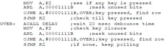
10 (a) D3 D0 = 1101 for the row, D3 D0 = 1011 for the column, indicate row 1 and column 3 are selected. This indicates that key 6 is pressed. (b) D3 D0 = 1011 for the row, D3 D0 = 0111 for the column, indicate row 2 and column 3 are selected. Then key B is pressed. 2.3 Program: The program used for detection and identification of the key activated goes through the following stages: 1. To make sure that the preceding key has been released, 0s are output to all rows at once, and the columns are read and checked repeatedly until all the columns are high. When all columns are found to be high, the program waits for a short amount of time before it goes to the next stage of waiting for a key to be pressed. 2. To see if any key is pressed, the columns are scanned over and over in an infinite loop until one of them has a 0 on it. Remember that the output latch is connected to rows, still have their initial zeros (in stage 1), making them grounded. After the keypress detection, it waits for 20-ms for the bounce and then scans the columns again. a) It ensures that the first key press detection was not an erroneous one due to spike noise. b) After the 20-ms delay, if the key is still pressed, then it goes to the loop (step 3) to detect the actual key pressed. 3. To detect which row the key pressed belongs to, it grounds one row at a time, reading the columns each time. If it finds that all columns are high, this means that the key press does not belong to that row. Therefore, it grounds the next row and continues until it finds the row, that the key pressed belongs to. Upon finding the row that the key pressed belongs to, it sets up the starting address for the lookup table holding the scan codes for that row. 4. To identify the key pressed, it rotates the column bits, one bit at a time, into the carry flag and checks to see if it is low. Upon finding the zero, it pulls out the ASCII code for that key from the look-up table. Otherwise, it increments the pointer to point to the next element of the look-up table. 2.4 Keyboard Program The program used for scanning and identifying the pressed key is shown below. The key press detection is standard for all keyboards but the process for determining which key is pressed varies. The look-up table method is shown in the following program. It can be modified to work with any matrix upto 8 x 8.
11

12 (Program Ref:The 8051 Microcontroller and Embedded Systems Using Assembly and C -Second Edition ) 3. Summary LCD display, interfacing of LCD with 8051 and the assembly programming are discussed. The Keyboard, interfacing of Keyboard to 8051 and assembly programming for interfacing are also discussed. 4. References 1. Muhammad Ali Mazidi, Janice Gillispie Mazidi, Rolin D. McKinlay, The 8051 Microcontroller and Embedded Systems Using Assembly and C -Second Edition, New Delhi (2000).
LCD AND KEYBOARD INTERFACING
 LCD AND KEYBOARD The 8051 Microcontroller and Embedded Systems: Using Assembly and C Mazidi, Mazidi and McKinlay Chung-Ping Young 楊中平 Home Automation, Networking, and Entertainment Lab Dept. of Computer
CHAPTER 12 LCD AND KEYBOARD INTERFACING
 CHAPTER 12 LCD AND KEYBOARD INTERFACING LCD Operation LCD is finding widespread use replacing LEDs The declining prices of LCD The ability to display numbers, characters, and graphics Incorporation of
e-pg Pathshala Subject: Computer Science Paper: Embedded System Module: Interfacing External Devices using Embedded C Module No: CS/ES/22
 e-pg Pathshala Subject: Computer Science Paper: Embedded System Module: Interfacing External Devices using Embedded C Module No: CS/ES/22 Quadrant 1 e-text In this lecture interfacing of external devices
Engr. A. N. Aniedu Electronic and Computer Engineering Nnamdi Azikiwe University, Awka
 Engr. A. N. Aniedu Electronic and Computer Engineering Nnamdi Azikiwe University, Awka INTRODUCTION Microcontroller vs General Purpose Microprocessor General-purpose microprocessors contains No RAM No
8051 Interfacing and Applications Microcontroller
 8051 Interfacing and Applications Objectives: At the end of this chapter, we will be able to: List the different devices that can be interfaced with 8051 Understand the working principle. Develop the following
1. Pin diagram of 8051 and ports
 e-pg Pathshala Subject : Computer Science Paper: Embedded System Module: Programming parallel ports Module No: CS/ES/9 Quadrant 1 e-text In this lecture pin diagram of 8051 controller will be shown and
INTERFACING 16 2 LCD WITH 8051
 INTERFACING 16 2 LCD WITH 8051 LCD display is an inevitable part in almost all embedded projects and this article is about interfacing 16 2 LCD with 8051 microcontroller. Many guys find it hard to interface
Applications of 8051 Microcontrollers
 Applications of 8051 Microcontrollers INTRODUCTION: A microcontroller is a versatile chip which can be used in various fields starting from simple consumer electronics, measuring devices to high end medical,
CPEG300 Embedded System Design. Lecture Interface with Peripheral Devices
 CPEG300 Embedded System Design Lecture 0 805 Interface with Peripheral Devices Hamad Bin Khalifa University, Spring 208 Typical Devices for an Electronics System Power generation PWM control Input devices
e-pg Pathshala Subject : Computer Science Paper: Embedded System Module: Interrupt Handling Module No: CS/ES/13 Quadrant 1 e-text
 e-pg Pathshala Subject : Computer Science Paper: Embedded System Module: Interrupt Handling Module No: CS/ES/13 Quadrant 1 e-text 1. Interrupt An interrupt is the occurrence of a condition--an event --
8051 I/O and 8051 Interrupts
 8051 I/O and 8051 Interrupts Class 7 EE4380 Fall 2002 Pari vallal Kannan Center for Integrated Circuits and Systems University of Texas at Dallas Agenda 8051 I/O Interfacing Scanned LED displays LCD displays
e-pg Pathshala Subject : Computer Science Paper: Embedded System Module: Serial Port Programming in Assembly Module No: CS/ES/12 Quadrant 1 e-text
 e-pg Pathshala Subject : Computer Science Paper: Embedded System Module: Serial Port Programming in Assembly Module No: CS/ES/12 Quadrant 1 e-text In this lecture, serial communication control register
e-pg Pathshala Subject: Computer Science Paper: Embedded System Module: Interrupt Programming in Embedded C Module No: CS/ES/20 Quadrant 1 e-text
 e-pg Pathshala Subject: Computer Science Paper: Embedded System Module: Interrupt Programming in Embedded C Module No: CS/ES/20 Quadrant 1 e-text In this lecture embedded C program for interrupt handling
ELEG3923 Microprocessor Ch.4 I/O Ports
 Department of Electrical Engineering University of Arkansas ELEG3923 Microprocessor Ch.4 I/O Ports Dr. Jingxian Wu wuj@uark.edu OUTLINE 2 8051 I/O programming I/O bit manipulation programming I/O PORT
 اصول ميکروکامپيوترها استاد درس: دکتر http://ee.iust.ac.ir/rahmati/index.htm rahmati@iust.ac.ir ا درس Email و Website برای تکاليف و... : http://eel.iust.ac.ir/rahmati/ ١ نوزدهم فصل ا شنايی با دستورالعمل
Chapter 4. Address. data. Input / Output Programming. Simplified Z80 System Architecture. Memory. program. data. Z80 I/O Programming
 Simplified Z80 System Architecture I/O Port Address Addr 8 16 00 Memory Addr 0000 Chapter 4 Input / Output Programming FF I/O Port Decoder IORQ RD WR 8 Z80 CPU data MEMRQ RD WR 8 Address Decoder program
JUMP, LOOP AND CALL INSTRUCTIONS
 JUMP, LOOP AND CALL INSTRUCTIONS After you have understood the tutorial on Introduction to assembly language which includes simple instruction sets like input/output operations, now it s time to learn
Microcontroller & Interfacing
 Course Title Course Code Microcontroller & Interfacing EC406 Lecture : 3 Course Credit Practical : 1 Tutorial : 0 Total : 4 Course Objective At the end of the course the students will be able to Understand
e-pg Pathshala Subject : Computer Science Paper: Embedded System Module: Programming Embedded Systems in C Module No: CS/ES/9 Quadrant 1 e-text
 e-pg Pathshala Subject : Computer Science Paper: Embedded System Module: Programming Embedded Systems in C Module No: CS/ES/9 Quadrant 1 e-text In this module, we will discuss about the embedded C programming
Principle and Interface Techniques of Microcontroller
 Principle and Interface Techniques of Microcontroller --8051 Microcontroller and Embedded Systems Using Assembly and C LI, Guang ( 李光 ) Prof. PhD, DIC, MIET WANG, You ( 王酉 ) PhD, MIET 杭州 浙江大学 2014 Chapter
 VALLIAMMAI ENGINEERING COLLEGE S.R.M. NAGAR, KATTANKULATHUR-603203. DEPARTMENT OF ELECTRICAL AND ELECTRONICS ENGINEERING VII-EEE EE6502- MICROPROCESSORS AND MICROCONTROLLERS QUESTION BANK UNIT I 1. What
e-pg Pathshala Subject : Computer Science Paper: Embedded System Module: Introduction to Computing Module No: CS/ES/1 Quadrant 1 e-text
 e-pg Pathshala Subject : Computer Science Paper: Embedded System Module: Introduction to Computing Module No: CS/ES/1 Quadrant 1 e-text About the course : In this digital world, embedded systems are more
Principle and Interface Techniques of Microcontroller
 Principle and Interface Techniques of Microcontroller --8051 Microcontroller and Embedded Systems Using Assembly and C LI, Guang ( 李光 ) Prof. PhD, DIC, MIET WANG, You ( 王酉 ) PhD, MIET 杭州 浙江大学 2011 Chapter
EEE3410 Microcontroller Applications Department of Electrical Engineering Lecture 4 The 8051 Architecture
 Department of Electrical Engineering Lecture 4 The 8051 Architecture 1 In this Lecture Overview General physical & operational features Block diagram Pin assignments Logic symbol Hardware description Pin
2. Write an 8051 program to generate a square wave of 25 khz at pin P2.3 using XTAL = 12 MHz. Solution:
 Assignment 2 1. Assume that 5 binary data items are stored in RAM locations starting at 50h, as shown below. Write a program to find the sum of all the numbers. The calculation is in 16-bit format and
~: Simple Programs in 8051 assembly language :~
 ~: Simple Programs in 8051 assembly language :~ Here some simple programs of 8051 are given to understand the operation of different instructions and to understand the logic behind particular program.
MICROCONTROLLER BASED WATER LEVEL CONTROL SYSTEM
 MICROCONTROLLER BASED WATER LEVEL CONTROL SYSTEM The present concept implements controlling of pump which pumps water from the sump (underground tank) to the overhead tank, using 8951 microcontroller.
AN1745. Interfacing the HC705C8A to an LCD Module By Mark Glenewinkel Consumer Systems Group Austin, Texas. Introduction
 Order this document by /D Interfacing the HC705C8A to an LCD Module By Mark Glenewinkel Consumer Systems Group Austin, Texas Introduction More and more applications are requiring liquid crystal displays
Chapter 3. Bit Addressable Area. By DeccanRobots
 Chapter 3 Bit Addressable Area By DeccanRobots What is Bit Addressable Area? FFh 2Fh 20h 00h Data Memory General purpose Memory Area Bit Addressable Memory Registers Memory Area from 20H to 2FH is Bit
COMP2121: Microprocessors and Interfacing. I/O Devices (II)
") COMP2121: Microprocessors and Interfacing I/O Devices (II) http://www.cse.unsw.edu.au/~cs2121 Lecturer: Hui Wu Session 2, 2017 1 Overview Keyboard LCD (Liquid Crystal Display) 2 2 Input Switches (1/2)
COMP2121: Microprocessors and Interfacing I/O Devices (II) http://www.cse.unsw.edu.au/~cs2121 Lecturer: Hui Wu Session 2, 2017 1 Overview Keyboard LCD (Liquid Crystal Display) 2 2 Input Switches (1/2)
e-pg Pathshala Subject : Computer Science Paper: Embedded System Module: Serial Port Communication Module No: CS/ES/11 Quadrant 1 e-text
 e-pg Pathshala Subject : Computer Science Paper: Embedded System Module: Serial Port Communication Module No: CS/ES/11 Quadrant 1 e-text In this lecture, serial port communication will be discussed in
UNIT 3 THE 8051-REAL WORLD INTERFACING
 UNIT 3 THE 8051-REAL WORLD INTERFACING 8031/51 INTERFACING TO EXTERNAL MEMORY The number of bits that a semiconductor memory chip can store is called chip capacity It can be in units of Kbits (kilobits),
Microcontroller Intel [Instruction Set]
![Microcontroller Intel [Instruction Set]](/thumbs/82/86620819.jpg "Microcontroller Intel [Instruction Set]") Microcontroller Intel 8051 [Instruction Set] Structure of Assembly Language [ label: ] mnemonic [operands] [ ;comment ] Example: MOV R1, #25H ; load data 25H into R1 2 8051 Assembly Language Registers
Microcontroller Intel 8051 [Instruction Set] Structure of Assembly Language [ label: ] mnemonic [operands] [ ;comment ] Example: MOV R1, #25H ; load data 25H into R1 2 8051 Assembly Language Registers
Interfacing ahantronix 128x64 Graphic Module to an 8-bitMicrocontroller
 Interfacing ahantronix 128x64 Graphic Module to an 8-bitMicrocontroller Introduction: Due to its thin profile, light weight, low power consumption and easy handling, liquid crystal graphic display modules
e-pg Pathshala Subject : Computer Science Paper: Embedded System Module: 8051 Architecture Module No: CS/ES/5 Quadrant 1 e-text
 e-pg Pathshala Subject : Computer Science Paper: Embedded System Module: 8051 Architecture Module No: CS/ES/5 Quadrant 1 e-text In this lecture the detailed architecture of 8051 controller, register bank,
Microcontroller and Embedded Systems:
 Microcontroller and Embedded Systems: Branches: 1. Electronics & Telecommunication Engineering 2. Electrical & Electronics Engineering Semester: 6 th Semester / 7 th Semester 1. Explain the differences
Question Bank Microprocessor and Microcontroller
 QUESTION BANK - 2 PART A 1. What is cycle stealing? (K1-CO3) During any given bus cycle, one of the system components connected to the system bus is given control of the bus. This component is said to
UNIT 2 THE 8051 INSTRUCTION SET AND PROGRAMMING
 UNIT 2 THE 8051 INSTRUCTION SET AND PROGRAMMING Instructions Alphabetical List of Instructions ACALL: Absolute Call ADD, ADDC: Add Accumulator (With Carry) AJMP: Absolute Jump ANL: Bitwise AND CJNE: Compare
Application Brief D-005
 Interfacing the Avago HDSP-2xxx LED Alphanumeric Displays with the Intel 8751H Microcontroller Application Brief D-005 Introduction The HDSP-21xx/-25xx series of products is ideal for applications where
8051 Overview and Instruction Set
 8051 Overview and Instruction Set Curtis A. Nelson Engr 355 1 Microprocessors vs. Microcontrollers Microprocessors are single-chip CPUs used in microcomputers Microcontrollers and microprocessors are different
EEE3410 Microcontroller Applications Department of Electrical Engineering Lecture 9 Simple I/O Interfacing
 Department of Electrical Engineering Lecture 9 Simple I/O Interfacing Week 10 1 In this Lecture. Interface 8051 with the following Input/Output Devices Switches Solenoid and relays LEDs Seven Segment Display
 Contents 8051 Instruction Set BY D. BALAKRISHNA, Research Assistant, IIIT-H Chapter I : Control Transfer Instructions Lesson (a): Loop Lesson (b): Jump (i) Conditional Lesson (c): Lesson (d): Lesson (e):
INTERRUPTS PROGRAMMING
 INTERRUPTS PROGRAMMING The 8051 Microcontroller and Embedded Systems: Using Assembly and C Mazidi, Mazidi and McKinlay Chung-Ping Young 楊中平 Home Automation, Networking, and Entertainment Lab Dept. of Computer
LABORATORY MANUAL Interfacing LCD 16x2, Keypad 4x4 and 7Segment Display to PIC18F4580
 LABORATORY MANUAL Interfacing LCD 16x2, Keypad 4x4 and 7Segment Display to PIC18F458 1. OBJECTIVES: 1.1 To learn how to interface LCD 16x2, Keypad 4x4 and 7Segment Display to the microcontroller. 1.2 To
LCD. Configuration and Programming
 LCD Configuration and Programming Interfacing and Programming with Input/Output Device: LCD LCD (liquid crystal display) is specifically manufactured to be used with microcontrollers, which means that
Architecture & Instruction set of 8085 Microprocessor and 8051 Micro Controller
 of 8085 microprocessor 8085 is pronounced as "eighty-eighty-five" microprocessor. It is an 8-bit microprocessor designed by Intel in 1977 using NMOS technology. It has the following configuration 8-bit
Interrupt Programming: Interrupts vs. Polling Method:
 UNIT 4: INTERRUPT PROGRAMMING & SERIAL COMMUNICATION WITH 8051: Definition of an interrupt, types of interrupts, Timers and Counter programming with interrupts in assembly. 8051 Serial Communication: Data
Assembly Language programming (3)
") EEE3410 Microcontroller Applications LABORATORY Experiment 3 Assembly Language programming (3) Name Class Date Class No. Marks Conditional Program Branching and Subroutine Call in 8051 Objectives To learn
EEE3410 Microcontroller Applications LABORATORY Experiment 3 Assembly Language programming (3) Name Class Date Class No. Marks Conditional Program Branching and Subroutine Call in 8051 Objectives To learn
FACULTY OF ENGINEERING LAB SHEET
 FACULTY OF ENGINEERING LAB SHEET MICROCONTROLLER AND MICROPROCESSOR SYSTEMS ECE2216 TRIMESTER 1 (2017/2018) MP2: Construction and programming of a basic electronic piano *Note: On-the-spot evaluation may
Programming of 8085 microprocessor and 8051 micro controller Study material
 8085 Demo Programs Now, let us take a look at some program demonstrations using the above instructions Adding Two 8-bit Numbers Write a program to add data at 3005H & 3006H memory location and store the
Timer-1 can be run using the internal clock, fosc/12 (timer mode) or from any external source via pin T1 (P3.5) (Counter mode).
 or from any external source via pin T1 (P3.5) (Counter mode).") EC 6504 MICROPROCESSOR AND MICROCONTROLLER Electronics and Communication Engineering Fifth Semester UNIT-V Part A 1. List the modes of Timer in 8051. [N/D16] The timers available in 8051 are Timer 0 (T0)
EC 6504 MICROPROCESSOR AND MICROCONTROLLER Electronics and Communication Engineering Fifth Semester UNIT-V Part A 1. List the modes of Timer in 8051. [N/D16] The timers available in 8051 are Timer 0 (T0)
Introduction To MCS-51
 Introduction To MCS-51 By Charoen Vongchumyen Department of Computer Engineering Faculty of Engineering KMITLadkrabang 8051 Hardware Basic Content Overview Architechture Memory map Register Interrupt Timer/Counter
Assembly Language programming (2)
") EEE3410 Microcontroller Applications LABORATORY Experiment 2 Assembly Language programming (2) Name Class Date Class No. Marks Arithmetic, Logic and Jump instructions Objectives To learn and practice the
EEE3410 Microcontroller Applications LABORATORY Experiment 2 Assembly Language programming (2) Name Class Date Class No. Marks Arithmetic, Logic and Jump instructions Objectives To learn and practice the
GUJARAT TECHNOLOGICAL UNIVERSITY
 GUJARAT TECHNOLOGICAL UNIVERSITY INSTRUMENTATION & CONTROL ENGINEERING (17) MICROCONTROLLER & INTERFACING (IC) SUBJECT CODE: 21517 B.E. 5 th SEMESTER Type of course: Core Engineering Prerequisite: 1. Fundamental
Microprocessors & Interfacing
 Lecture Overview Microprocessors & Interfacing Input/Output Devices Input devices Input switches Basics of switches Keypads Output devices LCD Lecturer : Dr. Annie Guo S2, 2008 COMP9032 Week8 1 S2, 2008
Microcontrollers. Fig. 1 gives a comparison of a microprocessor system and a microcontroller system.
 Syllabus: : Introduction to, 8051 Microcontroller Architecture and an example of Microcontroller based stepper motor control system (only Block Diagram approach). (5 Hours) Introduction to A microcontroller
80C451 operation of port 6
 INTRODUCTION The features of the are shared with the 80C5 or are conventional except for the operation of port 6. The flexibility of this port facilitates high-speed parallel data communications. This
ET2640 Microprocessors
 ET2640 Microprocessors Unit -2 Processor Programming Concepts Basic Control Instructor : Stan Kong Email : skong@itt-tech.edu Figure 2 4 Bits of the PSW Register 8051 REGISTER BANKS AND STACK 80 BYTES
ELEG3923 Microprocessor Ch.9 Timer Programming
 Department of Electrical Engineering University of Arkansas ELEG3923 Microprocessor Ch.9 Timer Programming Dr. Jingxian Wu wuj@uark.edu OUTLINE 2 Programming 8051 Timers Counter programming Timer programming
INTEGRATED CIRCUITS. AN408 80C451 operation of port 6
 INTEGRATED CIRCUITS March 1988 INTRODUCTION The features of the are shared with the 80C51 or are conventional except for the operation of port 6. The flexibility of this port facilitates high-speed parallel
Effective Utilization of a Microcontroller Port for Optimisation of Hardware
 Available online at www.sciencedirect.com Procedia Technology 4 (2012 ) 461 465 C3IT-2012 Effective Utilization of a Microcontroller Port for Optimisation of Hardware Mr. Sandeep Hanumante a and Prof.
Input/Output Devices. Lecturer: Sri Parameswaran Notes by: Annie Guo
 Input/Output Devices Lecturer: Sri Parameswaran Notes by: Annie Guo 1 Lecture Overview Input devices Input switches Basics of switches Keypads Output devices LCD 2 Input Switches Most basic binary input
Q 1 a) Attempt any THREE of the following: 12 TMOD.7 TMOD.6 TMOD.5 TMOD.4 TMOD.3 TMOD.2 TMOD.1 TMOD.0 GATE C/T M1 M0 GATE C/T M1 M0
 Attempt any THREE of the following: 12 TMOD.7 TMOD.6 TMOD.5 TMOD.4 TMOD.3 TMOD.2 TMOD.1 TMOD.0 GATE C/T M1 M0 GATE C/T M1 M0") Page 1 of 33 Q 1 a) Attempt any THREE of the following: 12 Q 1 a i) Describe Timer modes of 8051. Ans: Timer 0 and Timer 1 can both be used as either Counters or Timers. There are 4 different operating
Page 1 of 33 Q 1 a) Attempt any THREE of the following: 12 Q 1 a i) Describe Timer modes of 8051. Ans: Timer 0 and Timer 1 can both be used as either Counters or Timers. There are 4 different operating
UNIT THE 8051 INSTRUCTION SET AND PROGRAMMING
 UNIT THE 8051 INSTRUCTION SET AND PROGRAMMING Instructions Alphabetical List of Instructions ACALL: Absolute Call ADD, ADDC: Add Accumulator (With Carry) AJMP: Absolute Jump ANL: Bitwise AND CJNE: Compare
Control Transfer Instructions Jump, Loop, and Call. ECE473/573 Microprocessor System Design, Dr. Shiue
 Control Transfer Instructions Jump, Loop, and Call 1 Jump Instructions JZ label ; Jump if A=0 JNZ label ; Jump if A!=0 DJNZ reg, label ; Decrement and Jump if A (or reg.)!=0 CJNE A, byte ; Compare and
SN8F5000 Family Instruction Set
 SONiX Technology Co., Ltd. 8051-based Microcontroller 1 Overview SN8F5000 is 8051 Flash Type microcontroller supports comprehensive assembly instructions and which are fully compatible with standard 8051.
Embedded Controller Programming
 Embedded Controller Programming Counters, Timers and I/O in Assembly Language Ken Arnold Copyright 2000-2004 Ken Arnold 1 Outline Timer/Counters Serial Port More 8051 Instructions Examples Copyright 2000-2004
build_char macro P1,P2,P3,P4,P5,P6,P7,P8 ;Macro for building a custom character
 hold macro nop nop nop nop endm disp_str macro string ;Macro for sending string to LCD irpc char, if nul 'char' exitm endif mov a,#'char' lcall data_in endm endm build_char macro P1,P2,P3,P4,P5,P6,P7,P8
Digital Blocks Semiconductor IP
 805 SFR Bus Digital Blocks Semiconductor IP 805 Microcontroller Configurable Peripherals General Description The Digital Blocks (Configurable Peripherals) Microcontroller Verilog IP Core is complaint with
Module Contents of the Module Hours COs
 Microcontrollers (EE45): Syllabus: Module Contents of the Module Hours COs 1 8051 MICROCONTROLLER ARCHITECTURE: Introduction to Microprocessors and Microcontrollers, the 8051 Architecture, 08 1 and pin
Vidyalankar T.E. Sem. V [ETRX] Microprocessors and Microcontrollers I Prelim Question Paper Solution
![Vidyalankar T.E. Sem. V [ETRX] Microprocessors and Microcontrollers I Prelim Question Paper Solution](/thumbs/74/70555699.jpg "Vidyalankar T.E. Sem. V [ETRX] Microprocessors and Microcontrollers I Prelim Question Paper Solution") 1. (a) 1. (b) T.E. Sem. V [ETRX] Microprocessors and Microcontrollers I Prelim Question Paper Solution Priority modes. 1) Fully Nested Mode : It is a general purpose mode. IR 0 highest priority IR 1 lowest
1. (a) 1. (b) T.E. Sem. V [ETRX] Microprocessors and Microcontrollers I Prelim Question Paper Solution Priority modes. 1) Fully Nested Mode : It is a general purpose mode. IR 0 highest priority IR 1 lowest
LCM12232A LCM12232A. 122 x 32 1/32D STN( EL / 100VAC 400HZ LED / 4.2VDC
 LCM12232A 122 x 32 1/32D STN( ), EL LED EL / 100VAC 400HZ LED / 4.2VDC / 1 VDD-VSS 0 6.5 V Ta=25 LCD VDD-V0 0 12.0 V V1 0 VDD V VDD-VSS - 4.75 5.0 5.25 V LCD VDD-V0-4.5 5.5 6.5 V IDD - - 2.5 - ma LCD IEE
Microcontroller and Applications
 S.Y. Diploma : Sem. IV [DE/EJ/ET/EN/EX/EQ/IS/IC/IE] Microcontroller and Applications Time: 3 Hrs.] Prelim Question Paper Solution [Marks : 70 Q.1 Attempt any FIVE of the following : [10] Q.1(a) Define
Input/Output Ports and Interfacing LCD & Seven Segment Display
 Input/Output Ports and Interfacing LCD & Seven Segment Display Basic I/O Concepts Peripherals such as LEDs and keypads are essential components of microcontroller-based systems Input devices Provide digital
8051 Timers. Class 7 EE4380 Fall Pari vallal Kannan. Center for Integrated Circuits and Systems University of Texas at Dallas
 8051 Timers Class 7 EE4380 Fall 2002 Pari vallal Kannan Center for Integrated Circuits and Systems University of Texas at Dallas Introduction Timers Timing devices - Generate specific time delay Event
WINTER 14 EXAMINATION Subject Code: Model Answer Page No: 1/ 26
 WINTER 14 EXAMINATION Subject Code: 17509 Model Answer Page No: 1/ 26 Important Instructions to examiners: 1) The answers should be examined by key words and not as word-to-word as given in the model answer
Lab-Report Microprocessors
 Lab-Report Microprocessors Digital Voltage Meter (DVM) NO YES Name: Dirk Becker Course: BEng 2 Group: A Student No.: 9801351 Date: 05/May/1999 1. Contents 1. CONTENTS... 2 2. INTRODUCTION... 3 3. THE PROJECT...
LCM SPECIFICATIONS. LCM MODE: CHARACTER PRODUCTION CODE: LCM2002A REVISION: ver1.1 DATE: 2004/9/6. (using) LCM 2002A Sep 6th, 2004
 LCM 2002A Sep 6th, 2004") LCM SPECIFICATIONS (using) LCM MODE: CHARACTER PRODUCTION CODE: LCM2002A REVISION: ver1.1 DATE: 2004/9/6 010-62168698 62168699 www.qingyun-it.com P.1 of 14 PHYSICAL DATA Item Contents Unit LCD type STN
LCM SPECIFICATIONS (using) LCM MODE: CHARACTER PRODUCTION CODE: LCM2002A REVISION: ver1.1 DATE: 2004/9/6 010-62168698 62168699 www.qingyun-it.com P.1 of 14 PHYSICAL DATA Item Contents Unit LCD type STN
AN1239. HC05 MCU Keypad Decoding Techniques Using the MC68HC705J1A. Introduction
 Order this document by /D Rev. 1.0 HC05 MCU Keypad Decoding Techniques Using the MC68HC705J1A By David Yoder CSIC Applications Introduction This application note demonstrates the use of a matrix keypad
Displaying of Digital Clock through digital circuits and through Assembly Language Programs of 8051 microcontroller
 Dr. D. Chinni Krishna. Int. Journal of Engineering Research and Application ISSN : 2248-9622, Vol. 7, Issue 2, ( Part -3) February 2017, pp.01-06 RESEARCH ARTICLE www.ijera.com OPEN ACCESS Displaying of
Embedded Piano Interfaced with LCD
 Embedded Piano Interfaced with LCD Akshita Vinod Nichani U.G. Student, Electronics and Telecommunication Department, DJSCE Shruti Tushar Pistolwala U.G. Student, Electronics and Telecommunication Department,
8051 Microcontroller Assembly Programming
 8051 Microcontroller Assembly Programming EE4380 Fall 2002 Class 3 Pari vallal Kannan Center for Integrated Circuits and Systems University of Texas at Dallas Topics Machine code 8051 Addressing Modes
Design and Simulation of a Wind Speed Measuring System for Cup Anemometer using an 8-Bit Processor
 Design and Simulation of a Wind Speed Measuring System for Cup Anemometer using an 8-Bit Processor Akinkuade S. T Science Technology Department, Federal Polytechnic, Ado-Ekiti, Nigeria Oni S. A Physics
C51 Family. Architectural Overview of the C51 Family. Summary
 Architectural Overview of the C51 Family C51 Family Summary 1. Introduction............................................................ I.1. 1.1. TSC80C51/80C51/80C31.................................................................
UNIT-III ASSEMBLY LANGUAGE PROGRAMMING. The CPU can access data in various ways, which are called addressing modes
 8051 Software Overview: 1. Addressing Modes 2. Instruction Set 3. Programming 8051 Addressing Modes: UNIT-III ASSEMBLY LANGUAGE PROGRAMMING The CPU can access data in various ways, which are called addressing
Environmental Data Acquisition Using (ENC28J60)
") Environmental Data Acquisition Using (ENC28J60) Joshi Vaibhav Abstract -- Ethernet is a local area technology, which is used for reliable and efficient transfer and access of information across the devices
Environmental Data Acquisition Using (ENC28J60) Joshi Vaibhav Abstract -- Ethernet is a local area technology, which is used for reliable and efficient transfer and access of information across the devices
e-pg Pathshala Subject : Computer Science Paper: Embedded System Module: Microcontrollers and Embedded Processors Module No: CS/ES/2 Quadrant 1 e-text
 e-pg Pathshala Subject : Computer Science Paper: Embedded System Module: Microcontrollers and Embedded Processors Module No: CS/ES/2 Quadrant 1 e-text In this module, microcontrollers and embedded processors
Microprocessors 1. The 8051 Instruction Set. Microprocessors 1 1. Msc. Ivan A. Escobar Broitman
 Microprocessors 1 The 8051 Instruction Set Microprocessors 1 1 Instruction Groups The 8051 has 255 instructions Every 8-bit opcode from 00 to FF is used except for A5. The instructions are grouped into
CHAPTER ASSEMBLY LANGUAGE PROGRAMMING
 CHAPTER 2 8051 ASSEMBLY LANGUAGE PROGRAMMING Registers Register are used to store information temporarily: A byte of data to be processed An address pointing to the data to be fetched The vast majority
Lecture 5. EEE3410 Microcontroller Applications Department of Electrical Engineering Assembly Language Programming (1)
") Department of Electrical Engineering Lecture 5 8051 Assembly Language Programming (1) 1 In this Lecture 8051 programming model Assembly language syntax Operation codes and operands Machine instructions
Department of Electrical Engineering Lecture 5 8051 Assembly Language Programming (1) 1 In this Lecture 8051 programming model Assembly language syntax Operation codes and operands Machine instructions
ELEG3924 Microprocessor
 Department of Electrical Engineering University of Arkansas ELEG3924 Microprocessor Ch.2 Assembly Language Programming Dr. Jing Yang jingyang@uark.edu 1 OUTLINE Inside 8051 Introduction to assembly programming
CPEG300 Embedded System Design. Lecture 8 Timer
 CPEG300 Embedded System Design Lecture 8 Timer Hamad Bin Khalifa University, Spring 2018 Review 8051 port and port schematic Internal read/write data path Serial communication vs. parallel communication
CHAPTER 3 JUMP, LOOP, AND CALL INSTRUCTIONS
 CHAPTER 3 JUMP, LOOP, AND CALL INSTRUCTIONS Looping Repeating a sequence of instructions a certain number of times is called a loop Loop action is performed by DJNZ reg, Label The register is decremented
C H A P T E R 1 INTRODUCTION
 C H A P T E R 1 INTRODUCTION The mentioned project is based on the worlds most powerful intel controller 8051. Most of the services provided in todays world are voice interactive, you call up your bank
CPEG300 Embedded System Design. Lecture 6 Interrupt System
 CPEG300 Embedded System Design Lecture 6 Interrupt System Hamad Bin Khalifa University, Spring 2018 Correction Lecture 3, page 18: Only direct addressing mode is allowed for pushing or popping the stack:
Memory organization Programming model - Program status word - register banks - Addressing modes - instruction set Programming examples.
 MICROCONTROLLERS AND APPLICATIONS 1 Module 2 Module-2 Contents: Memory organization Programming model - Program status word - register banks - Addressing modes - instruction set Programming examples. MEMORY
MODEL ANSWER SUBJECT- MICROCONTROLLER(12187) CLASS-EJ5E CLASS TEST-02 Q1.)Attempt any THREE of the following.
 CLASS-EJ5E CLASS TEST-02 Q1.)Attempt any THREE of the following.") MODEL ANSWER SUBJECT- MICROCONTROLLER(12187) CLASS-EJ5E CLASS TEST-02 Q1.)Attempt any THREE of the following. (9M) 1) Describe the instructions SWAP A and MOVX@DPTR,A with one example. (3Marks) SWAP A
MODEL ANSWER SUBJECT- MICROCONTROLLER(12187) CLASS-EJ5E CLASS TEST-02 Q1.)Attempt any THREE of the following. (9M) 1) Describe the instructions SWAP A and MOVX@DPTR,A with one example. (3Marks) SWAP A
Embedded Systems and Software. LCD Displays
 Embedded Systems and Software LCD Displays Slide 1 Some Hardware Considerations Assume we want to drive an LED from a port. The AVRs can either source or sink current. Below is a configuration for sourcing.
 اصول ميکروکامپيوترها استاد درس: دکتر http://ee.iust.ac.ir/rahmati/index.htm rahmati@iust.ac.ir ا درس Email و Website برای تکاليف و... : http://eel.iust.ac.ir/rahmati/ ١ هجدهم فصل ا شنايی با تايمرهای 8051
ELEG3923 Microprocessor Ch.6 Arithmetic and Logics
 Department of Electrical Engineering University of Arkansas ELEG3923 Microprocessor Ch.6 Arithmetic and Logics Dr. Jingxian Wu wuj@uark.edu OUTLINE 2 Arithmetic instructions Signed number operations Logic