Two remote controller system with one Lossnay Basic System (Refer to page C-10) Multiple Lossnay units with one remote controller.
|
|
|
- Marcia Hutchinson
- 6 years ago
- Views:
Transcription
1 Control
2 CHAPTER 1 System Design 1. System Examples One with one remote Multiple units with one remote Two remote system with one Basic System (Refer to page C-10) Non-polar Two wires Power supply Remote A simple system in which is operated independently with one remote. Non-polar Two wires Remote Power supply Power supply Up to 15 units can be controlled at one time with one remote. Non-polar Two wires (Main) (Sub) Remote Power supply can be controlled from two remote locations. The remote gives priority to the last operation function request. Operation with an Air Conditioning Unit (Refer to page C-11) Operating with Mr. Slim (without Losnay remote ) MA remote Mr. Slim (Indoor unit) Power supply Power supply Use MA remote of Mr.Slim for switching ON/ or the fan speed. The ventilation mode is automatic ventilation. Operating with an External Device (Refer to page C-12) Operating with Mr. Slim (with remote ) Remote MA remote Mr.Slim (Indoor unit) starts or stops according to Mr.Slim. (PAC-SF40RM-E) M-NET System City Multi and Interlocked System Centralized Management System Air conditioning device and system control Outdoor unit (51) Indoor Indoor Indoor unit(01) (06) unit(02) (07) unit(03) MA remote MA remote Group setting Indoor unit(04) MA remote MA remote Indoor unit(05) Group 1 Group 2 Group 3 Group 4 (01) Centralized AE-200E (02) Power supply unit Remote ON/ remote PAC-YT40ANRA (03) (04) Remote (05) (06) Remote Group 1 Group 2 Group 3 Group 4 Group 5 MA remote (07) Interlocked operation setting One can be interlocked with 16 indoor units. In addition, can be connected for each units. Remote (08) Group setting (08) ( ) address ( ) address ON/, fan speed and ventilation mode control is possible from the centralized. Controller can set up the group including maximum of 15 indoor or units. C-2
3 CHAPTER 1 System Design / 1. System Examples Two remote system with multiple units Transmission cables Power supply (Main) Power supply TM4 (Sub) Remote Remote input terminal It is also possible to operate two remote units when using multiple units. Operating with an external device Non-polar Two wires Remote External device Power supply Power supply Selection of interlocked operation mode is possible. Delayed start interlocked operation is possible. starts or stops addording to the external device. Level signal or pulse signal input (12VDC, 24VDC, and volt-free contact) is available. Power supply Power supply Power supply (Main) (Sub) (Sub) MAX 15 units Remote () External device Power supply Operating switch for external device First TM4 1 2 TM4 1 2 Second Transmission cable Connect to remote Connect to third Interlocking/individual combined systems Interlock settings are possible with the inclusion of a group setting. (Joint use of the air conditioner remote and remote is possible.) M-NET transmission cable A TB5 B S Centralized AE-200E Group setting ON/ remote PAC-YT40ANRA Interlocked operation setting Shielded wire M-NET transmission cable input terminal block Power supply unit Transmission cables Outdoor unit(51) Indoor unit(01) (02) (03) (04) TM4 Remote input terminal MA remote Remote Group 1 Group 2 Remote ( ) address Address SA1 SA2 tens digit ones digit Address setting switch Applicable indoor units are C type or later (for use with MA remote ) models Set the different groups of indoor unit of air conditioner and unit. When the address number has been changed, the data in the memory is automatically reset. C-3
4 CHAPTER 1 System Design / 2. Function list and outline 2. Function list and outline 2.1 Function list of LGH-RVX-E No. 1 Basic function 2 Connectable remote Item LGH-RVX-E PZ-43SMF-E Remarks Page ON/ Refer to RC manual - ON timer, timer Refer to RC manual - Weekly timer 8 pattern in a day - Fan speed switching (4 fan speeds) : all fan speed can be used and be skipped - Fan speed switching (2 fan speeds) - PZ-43SMF-E: 2 of 4 fan speed can be used - Ventilation mode selection (Energy recovery / Bypass / Automatic) - Night-purge C-45 Night-purge from AG-150A/AE-200E Not possible from PZ-43SMF-E C-46 Max. fan speed operation during the first 30 minutes C-38 Multi ventilation mode C-37 (Indoor negative / positive pressure) C-38 Temperature display C-33 Operation lock Refer to RC manual - Function setting from remote C-29 One LGH to one remote operation C-10 Multiple LGHs to one remote operation (Max 15 units) (Max 15 units) One or more LGHs to 2 remote operation (Max 15 units) (Max 15 units) C-10 3 Usage in M-NET systems C-14 4 Error code display - 5 Maintenance Filter C-31 sign display core C-31 6 Operation by External City Multi C-14 external device or Use the cable attached with device Type of Mr. Slim (without remote ) LGH product C-11 input Mr. Slim (with remote ) PAC-SF40RM-E is necessary C-12 signal 12/24VDC input C-19 Volt-free contact input C-19 Pulse input C-20 Delay operation LGH starts operation after air conditioner/external device turns ON (15 or 30 min. later) (30 min. later) Interlocked RC switching is available ON/ interlock mode when interlocked C-23 ON interlock Available only when becoming ON for not to forget to start operations C-23 Available only when becoming interlock for not to forget to stop C-23 Function is available either operation with or without remote from RC is not available External priority ON/ interlock C-23 during operation 7 Switching fan speed by input signal PAC-SA88HA-E is necessary C-54 Switching ventilation mode by input signal PAC-SA88HA-E is necessary C-56 8 Output Operation monitor C-52 signal Malfunction monitor C-51 Bypass monitor or pre-heater C-48 C-51 : Possible to use. : Need accessory parts. : NOT available C-10 C-38 C-4
5 CHAPTER 1 System Design / 2. Function list and outline 2.2. Function list for from local remote and system The table below is a function table of s in the case that is NOT interlocked with City Multi indoor unit. Operation When not interlocked with City Multi ( group) Local remote remote ON/ remote System Advanced touch Centralized Centralized PZ-43SMF-E PAC-YT40ANRA AT-50B AG-150A AE-200E Maximum No. of controllable Groups/Units 1 / 15 *2 1 / 15 *2 16 / 50 *3 50 / 50 *3 50 / 50 *3 50 / 50 *3 ON/ Fan speed 4 fan speeds 3 of 4 fan 2 of 4 fan 2 of 4 fan 3 of 4 fan speeds *7 speeds speeds speeds 4 fan speeds *6 *6 *7 (ver7.30 or later) Ventilation mode Local permit / prohibit *4 Emergency stop *1 ON/ Fan speed Ventilation mode Temperature display Error indicator *5 Filter maintenance indicator core maintenance indicator Local permit / prohibit Status Monitoring Scheduling/ Recording Others One-day Times of ON/ per day Weekly Times of ON/ per week 8 x 7 16 x 7 24 x 7 24 x 7 Auto-off timer Minimum setting (minutes) Error record Operation restrictions (ON/, Ventilation mode, fan *8 *8 *8 speed) Operation restrictions (Fan speed skip setting) Night-purge (given conditions) (~ver.7.11) Night-purge (free setting) (ver.7.20~) Bypass temp. free setting Heater-On temp. free setting Fan power up after installation : Each group / Batched :Each group : Available under some conditions : NOT available *1: Only available for bulk operation. *2: *3: Up to 16 units in a group can be operated with one system *4: By using an external volt-free contact signal it is possible to send ON/ or Prohibit/Permit local remote operation commands to all units being controlled. *5: LED flashes during failure. *6: High fan speed of remote is fan speed 3 or 4 of unit. Lo is 1 or 2. *7: High fan speed of remote is fan speed 3 or 4 of unit. Middle is 2. Lo is 1. *8: It is possible to lock the touch screen operation. C-5
6 CHAPTER 1 System Design / 2. Function list and outline 2.3. Function list for interlocked with indoor unit from local remote and system The table below is a function table of s in the case that is interlocked with City Multi indoor unit. When interlocked with City Multi Operation Status Monitoring Scheduling/ Recording Others ON/ *1 Fan speed MA remote Local remote Smart ME Controller Simple MA remote ON/ remote System Advanced touch Centralized PAR-31MAA PAR-U02MEDA PAC-YT52CRA PAC-YT40ANRA AT-50B AG-150A 2 of 4 fan speeds *2 2 of 4 fan speeds *2 N N 2 of 4 fan speeds *2 2 of 4 fan speeds *2 Centralized AE-200E (Later ver7.20) 2 of 4 fan speeds *2 Ventilation mode Local permit / prohibit Emergency stop ON/ Fan speed Ventilation mode Temperature display Error indicator *3 Filter maintenance indicator core maintenance indicator Local permit / prohibit One-day *1 Times of ON/ per day Weekly *1 Times of ON/ per week 8 x 7 8 x 7 16 x 7 24 x 7 24 x 7 Auto-off timer *1 Minimum setting (minutes) Error history Operation restrictions (ON/, Ventilation mode, fan speed) Operation restrictions (Fan speed skip setting) Night-purge (given conditions) Night-purge (free setting) Bypass temp. free setting Heater-On temp. free setting Fan power up after installation : Each group / Batched :Each group : Available under some conditions : NOT available *1: When City Multi indoor unit is ON, is ON. *2: High fan speed of remote is fan speed 3 or 4 of unit. Lo is 1 or 2. *3: LED flashes during failure. C-6
7 CHAPTER 1 System Design / 3. System structure 3. System structure 3.1 Notes/Cautions when system configuration Basic system Operation by local remote (Refer to page C-10) Following local remote s can be used. (1) Different model remote s cannot be used together in a group. (2) Maximum 2 remote s can be connected in a group. (3) When two are used in a group, set one remote as main and the other as sub. (Refer to installation manual of.) (4) Adequate remote cable Securely connect the transmission cable from the remote to the terminal block (TM4 ). (No polarity).m. Wire type 2 core sheathed cable Wire diameter 0.3mm 2 Max overall length between and remote 200m Group setting units set in a group can be operated at the same time from local remote. (1) It is not possible to set and Indoor unit of air conditioner in a group. (2) When using local remote or interlocking with external device, ) each other become the same group. terminal bock (TM4 ) becomes the same group. (3) When connected to MELANS*, without remote and not interlocked with City Multi indoor units or any external device. ) is not necessary. However, in order to perform Night-purge function by using the system (AE-200E), connect them to each other. *MELANS : MITSUBISHI ELECTRIC's Air-conditioner Network System Interlocking with City Multi(Refer to page C-14) When and City Multi are connected to MELANS, it is possible to switch ON/ and High/Low operation from the indoor unit remote. Ventilation mode is fixed to Automatic mode. (1) One unit can be interlocked with up to 16 indoor units. (2) Perform interlock settings at the system or local remote of City Multi indoor unit. (3) The remote (, PZ-43SMF-E) can be used. (4) It is not possible to be interlocked together with Mr. Slim or external device. (5) When interlocking City Multi indoor unit and, ) of each unit. (6) Following interlock mode are NOT available.(refer to page C-23) C-7
8 CHAPTER 1 System Design / 3. System structure Interlocking with Mr. Slim (Refer to page C-11) When is connected to Mr. Slim with Slim- connection cable (enclosed accessory parts with unit), it is possible to switch ON/ and High/Low operation from the indoor unit remote. Ventilation mode is fixed to Automatic mode. (1) One can be interlocked with an indoor unit of air conditioner, but cannot be interlocked with multiple indoor units. (2) The remote (, PZ-43SMF-E) cannot be used on systems interlocked with Mr. Slim. (3) Use malfunction monitor output (TM3 ) to notice error. (4) It is not possible to be interlocked together with City Multi or external device. (5) It is not possible to stop unit during Mr. Slim operation Interlocking with indoor unit of air conditioner or other external device including other manufacturers (Refer to page C-11, C-19) It is possible to control unit ON/ by the signal to the terminal block TM2 from the external device interlocked with. (1) When volt-free contact is used. (Refer to page C-19) ). When using relay contact, contact rating must be more than 15 VDC/0.1 A, and minimum application load must be less than 1 ma. and the neutral side to TM2. (2) When 12VDC/24VDC level input is used. (Refer to page C-19) ). (No polarity) (3) When pulse input is used. (Refer to page C-20) More than 200 msec. More than 10 sec. (4) Controlling a group from the external device. ) of each unit. (5) Use signal cable 0.5mm 2 to 1.5mm 2 wire diameter. (6) Local remote can be used. (7) When not connected to MELANS and not using local remote, use monitor output (TM3 ) to notice error. (8) Cannot be interlocked together with City Multi or Mr. Slim Connecting to MITSUBISHI ELECTRIC's Air-conditioner Network System (MELANS) can be used with MELANS. Multiple units and groups can be operated by centralized. (1) Perform group setting from system. Refer to System manual. (2) The unit which has smallest address in a group is the main unit. Set the address number of each sub unit in the sequential number from the main unit address number. (3) Local remote can be used. (4) When interlocking with Mr. Slim, install M-NET connection adapter (PAC -SF83MA-E etc.) to outdoor unit in order to connect Mr. Slim to MELANS. Adequate transmission cable Wire type 2 core shielded wire CVVS / CPEVS Wire diameter 1.25mm 2 to 2.0mm 2 Max total length 500m Max length between and 200m power supply unit or outdoor unit C-8
9 CHAPTER 1 System Design / 3. System structure Main unit setting When multiple units are in one group, main unit setting is needed depending on system configuration or intended end-usage. Main unit exist only one in a group, and it communicates with MELANS, City Multi and external devices. There are two ways to set main unit, (1) Address setting and (2) setting. If both (1) and (2) are needed, make sure to set the same as main unit by both setting. Check the necessary settings in following chart. System configuration / Intended end-usage When unit make an error, its address number will be displayed on remote *1 Connection to M-NET Interlocking with indoor unit of non-mitsubishi air conditioner or other external device *1 Use the remote/local switching and the ON/ input (CN32) *1 Make the same operation to the units in the group by the following signal input *1*2*3 None of the above Main unit settings of multiple units (1) Address setting is necessary. Make any unit as main unit. (2) setting is necessary. Set the unit connected signal input as main unit. Main unit setting is not necessary. *1 Connect the terminal block (TM4 ) of each unit in the group. Refer to page C-3 *2 is necessary. *3 When performing a signal input to each unit in the group, (2) setting is not necessary. <Caution> unit. In this case, main unit setting is not necessary. (1) Address setting Address is identification number set to each unit of, indoor unit, outdoor unit, ME remote and system in MELANS. Set address number not to overlap in a system (connected with M-NET transmission cable). Set main unit address number within the range of 01 to 50. Be sure to set any address number in MELANS not to overlap. Address number is set in the sequential number from the main unit address number (see the example on the right). Be sure to set in MELANS not to overlap address number. M-NET Transmission cable (TB5 ) (TB5 ) (TB5 ) 1group Main(10) Sub(11) Sub(12) Sub(13) SA1 SA2 tens digit ones digit Address setting switch (2) setting External device Main (ON) Sub () Sub () Sub () Main / Sub SW No. (Factory setting) Sub unit SW5-10 ON Main unit (TM4 ) (TM4 ) (TM4 ) (TM4 ) Connect the input terminal block (TM4 ) of each units. C-9
10 CHAPTER 1 System Design / 3. System structure 3.2 Basic System Connecting with remote Securely connect the transmission cable from the remote to the terminal block (TM4 ). (1) Connecting with TM4 Transmission cables Remote input terminal Group1 Group2 Group3 Group Group1 Group2 Group3 Feature One unit and one remote. Multiple units and one remote. Multiple units and two remote s. (2) Connecting with PZ-43SMF-E PZ-43SMF-E PZ-43SMF-E PZ-43SMF-E PZ-43SMF-E Group1 Group2 Group3 Group Group1 Group2 Group3 Feature One unit and one remote. Multiple units and one remote. Multiple units and two remote s. <CAUTION> to which the external signal is input. C-10
11 CHAPTER 1 System Design / 3. System structure 3.3 Interlocking with Mr. Slim Connecting with Slim- connection cable Mr. Slim Indoor unit Slim- connection cable (Enclosed accessory parts with unit) MA remote <Feature> unit. <Caution>. (Refer to page C-51) < Wiring > of PCB. Ensure that all connections are secure and that the appropriate insulation is provided. Use extension cable sheathed PVC cable or cable 0.5 mm 2 to 0.75 mm 2. Always separate the power supply cable and the Slim- connection cable by 5 cm or more to prevent the unit from malfunction. external control input (TM2) Slim- connection cable CN2L Mr. Slim (Indoor unit) PCB Maximum 500 m <Operation> (1) Interlocking operation High is fan speed 4 and Low is fan speed 2 at the factory setting. They can be changed. (Refer to page C-40) (2) Individual operation SELECT button. F3 button to go through ventilation setting options in order of High, Low and Off. C-11
12 CHAPTER 1 System Design / 3. System structure Connecting with a-control remote operation adapter PAC-SF40RM-E Mr. Slim indoor unit Remote operation adapter PAC-SF40RM-E MA remote remote <Feature> <Caution> (Possible from remote.) indoor unit (outside air intake), unit cannot supply the air into the room properly because the fan of Mr. Slim does not work. <Wiring> lead wire side to the TM2 of PCB. (No polarity) Use transmission cable 0.5 mm 2 to 1.25 mm 2 sheathed PVC cable. Always separate the power supply cable and the signal cable by 5 cm or more to prevent the unit from malfunction. TM2 Indoor unit PCB TB1 operation 2 CN41 CN1 5 3 CN90 Maximum 100 m Remote operation adapter (PAC-SF40RM-E) <Operation> However, if there is a remote ( or PZ-43SMF-E), the unit will follow the settings from the remote. C-12
13 CHAPTER 1 System Design / 3. System structure Connecting with M-NET connection adapter PAC-SF83MA-E Centralized AE-200E ON/ remote PAC-YT40ANRA Power supply unit Mr. Slim outdoor unit PAC-SF83MA-E or PAC-SJ19MA-E is installed 01 Group setting Interlocked operation setting Mr. Slim indoor unit 02 Group1 MA remote remote Group2 <Feature> <Caution> (outside air intake), unit cannot supply the air into the room properly because the fan of Mr. Slim does not work. <Wiring> <Operation> (1) Interlock operation High is fan speed 4 and Low is fan speed 2 at the factory setting. (Refer to page C-40) (2) Individual operation SELECT button. F3 button to go through ventilation setting options in order of High, Low and Off. It is possible to set the fan speed when receiving High/Low signal. (Refer to page C-40) C-13
14 CHAPTER 1 System Design / 3. System structure 3.4 M-NET system Wiring. Type: Shielded wire (CVVS/CPEVS) Wire diameter: 1.25 mm 2 to 2.0 mm 2 Maximum torque: 0.5 N m M-NET transmission cable Shielded wire TB5 A B S M-NET transmission cable input terminal block Address setting Address setting is required when connecting to City Multi and MELANS. Refer to page C system <Feature> <Caution> <System example 1> Centralized AE-200E ON/ remote PAC-YT40ANRA Group setting Power supply unit remote remote remote Group1 Group2 Group3 ( ) address Group Group1 Group2 Group3 Feature One unit and one remote. unit can be controlled by remote. All of units can be controlled by centralized and ON/ remote, and each group can be controlled individually. Multiple units and two remote s. can be controlled by remote. Up to 2 remote s can be used in a group and they must be the same model. When 2 of are used, one of them must be sub setting. For details, refer to the installation manual of. When 2 remote s are used, the last touch has a priority. All of units can be controlled by centralized and ON/ remote, and each group can be controlled individually. Up to 15 units can be connected in a group. It is necessary to connect the terminal TM4 of each units. Multiple units without remote s. All of units can be controlled by centralized and ON/ remote, and each group can be controlled individually. Up to 16 units can be connected in a group. It is NOT necessary to connect the terminal TM4 of each unit. (It is necessary to connect the terminal TM4 of each unit when the Night-purge function is used by a centralized.) C-14
15 CHAPTER 1 System Design / 3. System structure City Multi and interlocked system <Feature> <Caution> <System example 2> Centralized AE-200E ON/ remote PAC-YT40ANRA Group setting Interlocked operation setting Power supply unit Outdoor unit(51) Indoor unit (01) 06 Indoor unit (02) 07 Indoor unit (03) (04) Indoor (05) Indoor unit unit MA remote MA remote remote MA remote MA remote Group 1 Group 2 Group 3 Group 4 Group 5 Group 6 Group 7 remote ( ) address Group Group2 Group4 Group7 Feature One unit which are interlocked to indoor unit of group 1. Operation of unit can be performed by MA remote. All of units can be controlled by centralized and ON/ remote, and each group can be controlled individually. One unit which is interlocked to multiple indoor units. Operation of unit can be performed by remote and 2 MA remote s. The last touch of remote or MA remote has a priority. All of units can be controlled by centralized and ON/ remote, and each group can be controlled individually. One unit can be interlocked to up to 16 indoor units. Multiple units which are interlocked to indoor unit of group 6. Operation of unit can be performed by 2 remote s and MA remote. The last touch of remote or MA remote has a priority. Up to 2 remote s can be used in a group and they must be the same model. When 2 s are used, one of them must be done sub setting. For details, refer to the installation manual of. All of units can be controlled by centralized and ON/ remote, and each group can be controlled individually. Up to 15 units can be connected in a group. It is necessary to connect the terminal TM4 of each units. C-15
16 CHAPTER 1 System Design / 3. System structure System configuration of more than 50 units ( and indoor units) <Feature> controlled from one AE-200E connected with three AE-50E. <System example 3> HUB PC for Centralized control (TG-2000A) Each unit can control up to a total of 2000 indoor,, and other units. System No.1 HUB AE-200E unit can control up to a total of 200 indoor,, and other units (when used with three AE-50E. Centralized AE-200E M-NET maximum 50 units Centralized AE-50E M-NET PZ-43SMF-E PZ-43SMF-E maximum 50 units Centralized AE-50E M-NET M-NET maximum 50 units Centralized AE-50E M-NET Outdoor unit MA remote M-NET Indoor unit maximum 50 units Outdoor unit Indoor unit Centralized AE-200E M-NET MA remote System No.2 maximum 50 units Group All System No. 1 System No. 2 Feature All of indoor and units can be controlled by the PC for centralized control. All units of system No.1 can be controlled by centralized AE-200E in system No. 1. Each indoor and unit can be controlled by each local remote. All units of system No.2 can be controlled by centralized AE-200E in system No. 2. unit can be controlled by remote. C-16
17 CHAPTER 1 System Design / 3. System structure Interlocking system with system interface MAC-333IF-E <Feature> MAC-333IF-E. <Caution> to page C-23. <System example 4> Centralized AE-200E ON/ remote PAC-YT40ANRA Group setting Interlocked operation setting (000) (201) Power supply unit Room air-conditioner Room air-conditioner MAC-333IF-E MAC-333IF-E MA remote remote Group 1 Group 3 Group 2 MA remote ( ) address Group Group 3 Feature One unit which is interlocked to multiple indoor units. Operation of unit can be performed by remote and 2 MA remote s. The last touch of remote or MA remote has a priority. It is possible to control unit from when air-conditioner is off. unit can be controlled by centralized and ON/ remote. It is impossible to stop unit when air-conditioner is operating. One unit can be interlocked to up to 16 indoor units. C-17
18 CHAPTER 1 System Design / 3. System structure Automatic-address-start-up function <Feature> unit. There is indoor unit(s) in a system. There is only one unit in a system. There are NO outdoor-air processing units (GUF series) in a system. <How to use Automatic-address-start-up function> <System example 4> Outdoor unit Group setting Indoor unit (00) (00) (00) (00) MA remote Group 1 Group 2 MA remote Group 3 MA remote Interlock Interlock Interlock (00) remote ( ) address <Function explanation> C-18
19 CHAPTER 1 System Design / 3. System structure 3.5 Interlocked system with an external device ON/ operation of unit is possible by the input signal from an air-conditioner, a BMS (Building Management Systems) etc. to the terminal (TM2 ~ ) of PCB. The type of input signal shall be volt-free contact or 12VDC/24VDC. Both level signal and pulse signal are available. <Caution> City Multi and Mr. Slim can NOT be interlocked to unit together with an external device How to use An external signal should be connected to the terminal (TM2 ~ ) of PCB. Maximum wiring length and the exact terminal number depend on the type of signal. Type of signal Max wiring length Terminal TM2 0.5mm 2 to 1.5mm 2 sheathed PVC cable external control input (TM2) External device Volt-free contact Volt-free contact 500m Maximum 500m <Caution> When use a relay contact, follow the usage conditions below; Rating: 15VDC/0.1A or more Min: 1mA or less When use a signal with polarity, the minus side should be connected to TM2, the plus side should be connected to TM2. TM2 0.5mm 2 to 1.5mm 2 sheathed PVC cable external control input (TM2) External device 24VDC or 12VDC See manual of the external device Overall connection extension length (Follow the operation manual for the external equipment.) 12 or 24VDC <Caution> TM2 is a non-polar terminal. The input signal should follow the usage conditions below; Voltage: 24VDC or 12VDC Current: 0.1A or more (1) Wiring Use 0.5 mm 2 to 1.5 mm 2 sheathed PVC cable for wiring. The signal wire should be away from the power cable and the wires of remote more than 5cm. (2) Level signal The duration of ON and should be 10 seconds or more. F More than 10sec Minimun 10sec. absence to the next ON Type of signal Volt-free contact 24VDC or 12VDC Volt-free contact operation When the contact is closed, is ON. When it is opened, is. When the signal has voltage, is ON. When it is 0VDC, is. 24VDC or 12VDC ON ON Level signal Contact closed Contact opened Level signal or VDC DC C-19
20 CHAPTER 1 System Design / 3. System structure (3) Pulse signal When using a pulse signal input, set the 2-2 ON or set the function No.28 by. See the table below. SW No. Function No. Data SW2-2 Pulse input setting 0 (Factory setting) priority 28 (Factory setting) 1 NOT pulse input ON 2 Pulse input The duration of ON should be 200 msec. or more and 10 sec. or more absence is necessary to the next pulse. F More than 200 msec. Minimun 10sec. absence to the next pulse ON/ of unit is inverted each time a pulse signal is inputted. Volt-free contact 24VDC or 12VDC ON ON Pulse signal Contact closed Contact opened Pulse signal DC or VDC DC <Caution> In conditions of pulse input is set to ON, following functions are not available. (4) Group control In the case that multiple units are controlled by an input signal, follow the connection and setting below. of each units. (5) Interlocked to multiple external devices When the input signal is level signal, one unit can be interlocked to multiple external devices.. ON No.1 external device No.2 external device No.3 external device Contact closed Contact opened Contact closed Contact opened Contact closed Contact opened C-20
21 CHAPTER 1 System Design / 3. System structure Remote output component External control input (TM2) 500 m or less External device External device External device External device Power External device operation switch Power External device operation switch Power External device operation switch Power External device operation switch (6) Operation monitor output (Refer to page C-52) The ON/ status of can be ed by the operation monitor output. When unit is ON, the relay X15 of PCB (TM3 ) is closed. The operation monitor output follows the external input signal with maximum 200 msec delay. (7) Malfunction monitor output (Refer to page C-51) When unit is not connected to MELANS or remote, the error monitor output function should be used to know the malfunction of unit. When unit has an error, the relay X14 of PCB (TM3 ) is closed Interlocked system with non-mitsubishi air-conditioner Signal Non-Mitsubishi air-conditioner remote <Feature> <Caution> mode. Use malfunction monitor output function to notice error. C-21
22 CHAPTER 1 System Design / 3. System structure Interlocked system with BMS (Building Management Systems) Signal BMS Main Sub Sub Max 15 units per group remote <Feature> For details, refer to page C-54. <Caution> mode. Use malfunction monitor output function to notice error Combination system of MELANS and external devices Power supply unit System (201) Non-Mitsubishi air conditioner Group1 Group2 Group3 remote Control-equipment remote Control-equipment ( ) address Group Group1 Group2 Group3 Feature MELANS control unit. unit is interlocked with non-mitsubishi air-conditioner. unit turns ON/ by a signal from the air-conditioner. unit can be controlled, ON/ or fan speed switching, by remote or system individually. When an error occurs, the error number will appear on remote and system. MELANS control unit. unit is interlocked to a control-equipment. unit turns ON/ by a signal from a control-equipment. unit can be controlled, ON/ or fan speed switching, by remote or system individually. When an error occurs, the error number will appear on remote and system. MELANS control unit. unit is interlocked to a control-equipment. Group 3 is an example as same as group 2 other than remote. unit turns ON/ by a signal from a control-equipment. unit can be controlled, ON/ or fan speed switching, by system individually. When an error occurs, the error number will appear on system. C-22
23 CHAPTER 1 System Design / 3. System structure Interlock mode setting (External control operating mode) There are four operation modes of interlocked system from external devices. a: ON/ interlock mode (Factory setting) b: ON interlock mode c: interlock mode d: External priority ON/ interlock mode <How to select the mode> Set the 5-7 and 5-8 or function setting of as the table below. SW No (Factory setting) Function No. Data 0 (Factory setting) priority 1 a) ON/ interlock mode Interlock setting SW5-7 SW ON b) ON interlock mode ON 3 c) interlock mode 5-7 ON 5-8 ON 4 d) External priority ON/ interlock mode <Caution> function setting No.28 by. available. Do NOT set to other mode. button is invalid when both the and external device is operating. when both the and external device is operating. No special indicator on the display. external device is operating. (The display changes to when pressing ON/ button, but it returns soon.) C-23
24 CHAPTER 1 System Design / 3. System structure a) ON/ interlock mode (Factory setting) unit turns ON externally. unit turns externally. Regardless of the signal of external device, unit can be controlled by remote and MELANS. < ON signal> < signal> ON signal signal Non-Mitsubishi air-conditioner ON unit turns ON externally Non-Mitsubishi air-conditioner unit turns externally <Level signal> Remote [ON/] button pressed unit operation condition ON ON ON ON External signal ON signal signal <Pulse signal> Remote [ON/] button pressed unit operation condition ON ON ON ON ON ON External signal b) ON interlock mode unit turns ON externally. unit does not turn externally. Regardless of the signal of external device, unit can be controlled by remote and MELANS. Note; This mode is not available when is interlocked with Mr.Slim or C/M indoor unit via TM2 ~. < ON signal> < signal> Non-Mitsubishi air-conditioner ON signal ON unit trurns ON externally Non-Mitsubishi air-conditioner signal ON unit does not turn externally <Level signal> Remote [ON/] button pressed unit operation condition ON ON ON ON External signal ON signal signal <Pulse signal> Remote [ON/] button pressed unit operation condition ON ON ON ON ON External signal C-24
25 CHAPTER 1 System Design / 3. System structure c) interlock mode unit does not turn ON externally. unit turns externally. Regardless of the signal of external device, unit can be controlled by remote and MELANS. Note; This mode is not available when is interlocked with Mr.Slim or C/M indoor unit via TM2 ~. < ON signal> < signal> Non-Mitsubishi air-conditioner ON signal unit does not turn ON externally Non-Mitsubishi air-conditioner signal unit turns externally <Level signal> Remote [ON/] button pressed ON ON unit operation condition ON ON External signal ON signal signal <Pulse signal> Remote [ON/] button pressed ON ON unit operation condition ON ON External signal d) External priority ON/ interlock mode unit turns ON externally. unit turns externally. During unit is operating by signal of external device, can NOT be turned by remote or MELANS. Note; This mode is NOT available with pulse signal. < ON signal> < signal> ON signal signal Non-Mitsubishi air-conditioner ON unit turns ON externally. Non-Mitsubishi air-conditioner unit turns externally. Cannot control <Level signal> Remote [ON/] button pressed ON unit operation condition ON ON ON <Pulse signal> Not available External signal ON signal signal C-25

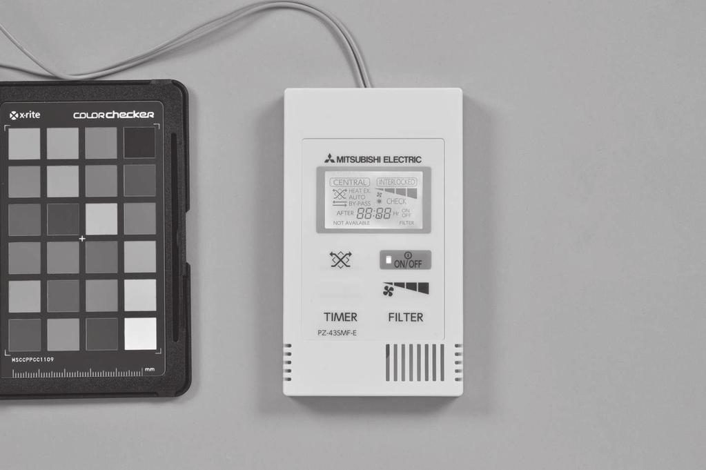
26 CHAPTER 2 Function 1. Comparison of remote LGH-RVX-E series can be connected to 2 types of remote s. <Appearance> remote PZ-43SMF-E Exterior Size mm mm Color <Installation> Remote PZ-43SMF-E M-NET address No need No need Main/Sub setting Necessary when using 2 remote s in a group No need connection Group change Not available from RC. from system is necessary. Also the wiring between units and RC should be reed and modified. Max No. of remote in a group 2 2 Features Same face with Mitsubishi A/C RC Various functions like weekly timer Night-purge, Bypass free setting etc. are available. *It is NOT available to use both and PZ-43SMF-E in a group. <Function> Basic functions like ON/, fan speed switching and ventilation mode selecting are available. Small installation space Function (Communicating mode) PZ-43SMF-E Fan speed selection 4 fan speeds 2 of 4 fan speeds Ventilation mode selection Energy recovery / Bypass / Automatic Energy recovery / Bypass / Automatic Night-purge (time) Any time selectable No Night-purge (fan speed) Selectable from 4 fan speeds No setting and function setting from RC No Bypass temp. free setting No Pre-heater control free setting No Fan power up after installation No 0-10VDC external input ON/ timer Auto-Off timer No Weekly timer No Operation restrictions (ON/, Ventilation mode, fan speed) No Operation restrictions (Fan speed skip setting) No Screen contrast adjustment No Language selection No (English only) Initializing remote No Filter cleaning sign core cleaning sign No Error indication Error history No OA/RA/SA temp. display No *ON/ timer of PZ-43SMF-E : count-down timer to ON/ C-26
27 CHAPTER 2 Function / 2. Function setting 2. Function setting 2.1 Model selection switch 6 is to identify the model for PCB. When replacing to new PCB, set the same setting as old one LGH-15RVX-E ON LGH-25RVX-E ON LGH-35RVX-E ON ON LGH-50RVX-E ON LGH-65RVX-E ON ON LGH-80RVX-E ON ON LGH-100RVX-E ON ON ON LGH-150RVX-E ON LGH-200RVX-E ON ON * Do not change from factory setting. If changed, please set as factory setting. 2.2 Function selection switches ( 2, 5) Set the selection switches ( 2, 5) to perform the appropriate function ON Trial operation No. 28 Pulse input setting No. 63 External fan speed input setting (0-10 VDC) No. 6 Indoor negative pressure setting No. 7 Indoor positive pressure setting No. 63 External fan speed input setting (0-10 VDC) No. 51 Automatic ventilation mode setting No. 57 Operation monitor output synchronized with exhaust fan or supply fan No. 61 Fan speed for air volume High input No. 62 Fan speed for air volume Low input ON No. 9 Delay start setting for air conditioner starting No. 57 Operation monitor output synchronized with exhaust fan or supply fan 3 No. 13, No. 14 Exhaust fan setting 4 No. 5 Automatic recovery setting after power interruption 5 No. 1 Filter maintenance and fan power up setting against filter choking 6 No. 58 Bypass monitor output or pre-heater output setting 7 No. 15 Interlock mode setting 8 No. 15 Interlock mode setting 9 10 No. 14 Exhaust fan setting at OA temperature lower than -15 C Main unit setting (Refer to page C-9) No. ** Shows the function No. which can be set from remote C-27
28 CHAPTER 2 Function / 2. Function setting 2.3 Function setting from Function list No *1 C-28 Function Filter maintenance and fan power up setting against filter choking Data priority Indicator available Fan power up N/A Indicator N/A Fan power up N/A Indicator available Fan power up available Factory setting No. Reference page Individual setting C-31-2 core maintenance indicator setting N/A Available 0 N/A C-31-5 Automatic recovery setting after power interruption 6 Indoor negative pressure setting 7 Indoor positive pressure setting priority priority priority Stop when the power is ON N/A N/A Start when the power is ON Supply 1 down Exhaust 1 down Return to the state before interruption Supply 2 down Exhaust 2 down C C C-38 Max. fan speed setting during the first 30 8 N/A Available 0 N/A C-38 minutes 9 Delay start setting for air conditioner starting N/A 15 min 30 min C-38 - priority Exhaust fan setting during air conditioner 13 Stop No change C-39 - defrosting priority 14 Exhaust fan setting at OA temperature lower than -15 C 15 Interlock mode setting 28 Pulse input setting Night-purge setting 1) *30 Air volume Night-purge setting 2) *31 Outdoor and indoor temperature difference Night-purge setting 3) *32 Threshold of outdoor temperature *34 Input priority setting priority priority priority N/A Stop ON/ interlock Non-pulse input Fan speed 1 Fan speed 1 or 2 ON interlock Pulse input Fan speed 2 No change interlock 0 External input given priority C-39 - C C-20 - Fan speed 3 Fan speed 4-0 N/A C-47-0 C 1 C 2 C 3 C 4 C 5 C 6 C 7 C 5 N/A C-47 - Data 0 to 15 --> Threshold temperature for Night-purge 15 C to 30 C 2 N/A C-47 - Main unit input priority Individual input priority 0 N/A C Outdoor temperature display setting N/A Available 0 N/A C Indoor temperature display setting N/A Available 0 N/A C Calculated supply air temperature display setting N/A Available 0 N/A C Temperature exchange efficiency setting (tens digit) Data 0 to 9 --> tens digit of temperature exchange efficiency 0 to 9 7 N/A C Temperature exchange efficiency setting (ones digit) Data 0 to 9 --> ones digit of temperature exchange efficiency 0 to 9 0 N/A C-34 - *41 Outdoor temperature correction Data 0 to 14 --> Outdoor temperature correction -7 C to 7 C 7 N/A C-35 - *42 Indoor temperature correction Data 0 to 14 --> Room temperature correction -7 C to 7 C 7 N/A C-35 - *51 Automatic mode setting Automatic mode setting 1) *52 Outdoor and indoor temperature difference Automatic mode setting 2) *53 The lowest outdoor temperature setting Automatic mode setting 3) *54 The lowest indoor temperature setting priority *55 Supply fan power up setting N/A *56 Exhaust fan power up setting N/A Operation monitor output synchronized with exhaust fan or supply fan Bypass monitor output or pre-heater output setting Pattern A Pattern B Free setting C-43 - Data 0 to 7 --> Temperature difference 0 C to 7 C 0 N/A C-44 - priority priority Data 0 to 15 --> Lowest outdoor temperature 10 C to 25 C 6 N/A C-44 - Data 0 to 15 --> Lowest indoor temperature 15 C to 30 C 1 N/A C-44-1 level up 1 level up Operation monitor output Bypass monitor output 2 level up 2 level up SA fan monitor output Operation monitor output for pre-heater 3 level up 3 level up SA fan monitor with delay operation 4 level up 4 level up - 0 N/A C-40-0 N/A C C C-51 Pre-heater output setting 1) *59 ON temperature 0 C -1 C -2 C -3 C -4 C -5 C -6 C -7 C 0 N/A C-48 Pre-heater output setting 2) *60 interval 1 hr 2 hrs 3 hrs 4 hrs 5 hrs - 0 N/A C-49 *61 Fan speed for air volume High input Fan Fan priority speed 4 speed C-40 - *62 Fan speed for air volume Low input Fan Fan priority speed 2 speed C-40 - External fan speed input setting ( *63 N/A Pattern X Pattern Z - 0 VDC) priority 2-6 C Initialization - Initialize 0 N/A C-36 - This table shows the summary of function settings. Please refer to the following pages for more details. The functions indicated with * are newly added or modified from LGH-RX 5-E series. The functions indicated with N/A in the No. column are available only when using with remote. The functions indicated with in the Individual setting column are avilable to set the data for each in the multiple group individually. Refer to page C-30.
29 CHAPTER 2 Function / 2. Function setting How to set function setting from Make the units' function settings from as necessary (Not available from PZ-43SMF-E). Every modified setting needs to be recorded to trace. <Button operation> 1 Main Main menu Initial setting Service Main display: Cursor Page 2/2 Press the MENU button. The main menu will appear. Select Service on the Main menu and press the SELECT button. : ON/ button : SELECT button : RETURN button 2 Service menu Maintenance password Remote Function setting Initializing Main menu: Cursor 2/2 : MENU button Select Function on the Service Menu screen, and press the SELECT button. 3 M-NET address Function No. Data Function Select: Cursor Function setting Set / Conf Function setting Address M-NET address 3 Function No. 32 Data 2 Sending data The Function screen will appear. Press the F1 or F2 button to move the cursor to one of the following: M-NET address, function setting number, or setting value. Then, press the F3 or F4 button to change the settings to the desired settings. Once the settings have been completed, press the SELECT button. A screen will appear that indicates that the settings information is being sent. To the current settings of a given unit, enter the setting for its M-NET address and function setting number, select Conf for the Function, and press the SELECT button. A screen will appear that indicates that the settings are being searched for. When the search is done, the current settings will appear. Function setting M-NET address 3 4 Function No. 32 Data 2 completed Return: When the settings information has been sent, a screen will appear that indicates its completion. To make additional settings, press the RETURN button to return to the screen shown in Step 3 above. Set the function numbers for other units by following the same steps. Navigating through the screens To return to the Service Menu screen... MENU button To return to the previous screen... RETURN button C-29
30 CHAPTER 2 Function / 3. Function setting contents <Cautions of M-NET address setting> Only when each has individual M-NET address, it is possible to do individual function setting by selecting its M-NET address. In other cases when address setting is not done, All should be selected for M-NET address. In the case of multiple units system, both Bulk setting and Individual setting is possible. Use Bulk setting for the functions which cannot be available to use Individual setting. Refer to the table in page C-28. Note; All ) All ) 3. Function setting contents 3.1 Trial Operation After the system has been installed and before the ceiling panel is installed, make sure that wires are properly connected, then test the system s operation, referring to the operation manual for the remote Trial operation using the remote s () Follow the procedure shown in the operation manual for the remote the functions below. (1) Start operation. (2) Fan speed selection. (3) Ventilation mode selection. (4) Stop operation trial operation This function can be used in the following situations. C or lower. (To Bypass damper operation) (1) Supply power to the unit. (2) Turn the trial operation switch (2-1) ON. Terminal DIP- SW (3) Check each function is operating normally. (4) Turn the trial operation switch (2-1) Complete system trial operation Use the remote for the indoor unit or the operating switches for the external device and confirm that the indoor unit and are interlocked. If delay time has been set, that the operates after the delay time has passed. Minutes Seconds FanSpeed STOP 4 STOP 4 - Ventilation mode Bypass TM3 SW5-6 Bypass monitor output ON ON Pre-heater output ON TM3 SW2-8/ / EA fan monitor output ON SW5-2 /ON SA fan monitor output ON ON/ or SA fan monitor output ON/ON delay operation ON TM3 Malfunction monitor output ON Error code 0900 appears on the remote. Use MELANS to confirm the operation of the. C-30
31 CHAPTER 2 Function / 3. Function setting contents 3.2 Pulse input setting Refer to page C Filter maintenance and fan power up setting against filter choking Set the schedule for filter cleaning based on the estimated concentration of dust in the air. When fan power up is available, exhaust and supply fans power up at 1,000 hours and 2,000 hours gradually. If function No.55 or No.56 is already worked, fan power up function may not be available. Estimated hour differs by actual operated fan speed. Filter Fan power maintenance Function SW No. UP No. Data indicator 0 (Factory setting) priority Indicate at 1 SW5-5 1 estimated 3,000 hrs N/A (Factory setting) 2 N/A N/A ON 3 Indicate at estimated 3,000 hrs Available <Caution> or the remote. After cleaning the filter, the filter cleaning icon can be reset. Refer to the Instruction book for the remote. 3.4 core maintenance indicator setting Set to enable core maintenance indicator. Estimated hour differs by actual operated fan speed. This function is N/A from unit. Estimated hour differs by actual operated fan speed. core maintenance Function SW No. indicator No. Data 0 (Factory N/A N/A 2 setting) 1 Indicate at estimated 6,000 hrs 3.5 Automatic recovery setting after power interruption Set for automatic recovery following power interruption. Function SW No. No. Data Automatic recovery 0 (Factory priority setting) SW5-4 (Factory setting) 5 1 Stop when the power is on 2 Start when the power is on ON 3 returns to the state before interruption C-31
32 CHAPTER 2 Function / 3. Function setting contents 3.6 Indoor negative pressure setting Refer to Fan speed control (C-37). 3.7 Indoor positive pressure setting Refer to Fan speed control (C-38). 3.8 Max. fan speed setting during the first 30 minutes Refer to Fan speed control (C-38). 3.9 Delay start setting for air conditioner starting Refer to Fan speed control (C-38) Exhaust fan setting during air conditioner defrosting or at OA temperature lower than -15 C Refer to Fan speed control (C-39) Interlock mode setting Refer to Interlocked system with an external device (C-23) Pulse input setting Refer to 4.5 Interlocked system with an external device (C-20) Night-purge setting 1) Air volume Refer to Night-purge function (C-47) Night-purge setting 2) Outdoor and indoor temperature difference Refer to Night-purge function (C-47) Night-purge setting 3) Threshold of outdoor temperature Refer to Night-purge function (C-47) Input priority setting Refer to Input terminal (C-57). C-32
33 CHAPTER 2 Function / 3. Function setting contents 3.17 Outdoor temperature display setting Set to display outdoor temperature detected by unit thermistor or not. manual of (During Night-purge, outdoor temperature is not displayed.) Function Outdoor temperature display SW No. No. Data 0 (Factory N/A N/A 36 setting) 1 Display on the screen of *Outdoor temp. display flashes when 0 C or lower and 38 C or higher Indoor temperature display setting Set to display indoor temperature detected by unit thermistor or not. manual of (During Bypass ventilation and Night-purge, indoor temperature is not displayed.) Function Indoor temperature display SW No. No. Data 0 (Factory N/A N/A 37 setting) 1 Display on the screen of *Indoor temp. display flashes when 8 C or lower and 38 C or higher 3.19 Calculated supply air temperature display setting Set to display calculated supply air temperature or not. manual of (During Bypass ventilation and Night-purge, calculated supply air temperature is not displayed.) Calculated supply Function SW No. air temperature display No. Data 0 (Factory N/A N/A 38 setting) 1 Display on the screen of *Supply air temp. display flashes when 8 C or lower and 38 C or higher. C-33
34 CHAPTER 2 Function / 3. Function setting contents 3.20 Temperature exchange efficiency setting Set the tens digit of temperature exchange efficiency which is used to calculate supply air temperature. Tens digit of temperature Function SW No. exchange efficiency No. Data N/A (Factory 7 setting) Set the ones digit of temperature exchange efficiency which is used to calculate supply air temperature. Ones digit of temperature Function SW No. exchange efficiency No. Data 0 (Factory 0 setting) N/A Note; No.39 is 8 and setting data of No.40 is 5, the temperature exchange efficiency C-34
35 CHAPTER 2 Function / 3. Function setting contents 3.21 Outdoor temperature correction Set the correction for the outdoor temperature displayed on the screen by function No.36. SW No. N/A The correction to thermistor Function detection No. Data 0-7 C 1-6 C 2-5 C 3-4 C 4-3 C 5-2 C 6-1 C 7 41 (Factory 0 C setting) 8 +1 C 9 +2 C C C C C C For example, in the case that setting data is 10, when the detected temp. is 20 C, the display temp. becomes 23 C. <Caution> manual of 3.22 Indoor temperature correction Set the correction for the indoor temperature displayed on the screen by function No.37. SW No. N/A The correction to thermistor Function detection No. Data 0-7 C 1-6 C 2-5 C 3-4 C 4-3 C 5-2 C 6-1 C 7 42 (Factory 0 C setting) 8 +1 C 9 +2 C C C C C C For example, in the case that setting data is 10, when the detected temp is 20 C, the display temp. becomes 23 C. <Caution> manual of C-35
36 CHAPTER 2 Function / 3. Function setting contents 3.23 Automatic ventilation mode setting Refer to Ventilation mode control (C-43) 3.24 Automatic mode setting 1) Outdoor and indoor temperature difference Refer to Ventilation mode control (C-44) 3.25 Automatic mode setting 2) The lowest outdoor temperature Refer to Ventilation mode control (C-44) 3.26 Automatic mode setting 3) The lowest indoor temperature setting Refer to Ventilation mode control (C-44) 3.27 Supply fan power up setting and Exhaust fan power up setting Refer to Fan speed control (C-40) 3.28 Operation monitor output synchronized with exhaust fan or supply fan Refer to External input / output terminal (C-52) 3.29 Bypass monitor output or Pre-heater output setting Refer to External input / output terminal (C-51) 3.30 Pre-heater output setting 1) ON temperature Refer to Cautions of operation in cold region (C-48) 3.31 Pre-heater output setting 2) interval Refer to Cautions of operation in cold region (C-49) 3.32 Fan speed for air volume High input Refer to Fan speed control (C-40) Fan speed for air volume Low input Refer to Fan speed control (C-40) External fan speed input setting (0-10 VDC) Refer to External input / output terminal (C-54) Initialization Set to initialize the remote function setting. All function settings which are changed by users are cancelled. Function SW No. No. Data 0 N/A N/A Available Initialization C-36
37 CHAPTER 2 Function / 4. Fan speed control 4. Fan speed control 4.1 Fan speed control for each system Following controls can be performed according to system configuration. Remote s System Air volume System s Stand-alone/multiple remote and remote the remote. : Basic System M-NET Control Stand-alone/multiple and remote : PZ-43SMF-E System interlocked with Mr.Slim Level signal/pulse signal output device and external device only Stand-alone/multiple and remote : Stand-alone/multiple and remote : PZ-43SMF-E M-NET central control system M-NET System interlocked with City Multi indoor units remote PZ-43SMF-E MA remote PAR-31MAA (Remote connection prohibited with ) None Fixed to fan speed 4 remote remote PZ-43SMF-E M-NET Smart ME Controller PAR-U02MEDA MA remote PAR-31MAA the remote. Fan speed High / Low are selectable by ventilation operation of the remote. the remote the remote. Selectable fan speed depends on the remote. Fan speed High / Low are selectable by ventilation operation of the remote. 4.2 Fan speed control by function settings Fan speed controls listed below can be set by function setting of remote or 2, Indoor negative pressure setting Exhaust fan speed is bigger than supply fan speed. Remote indicates fan speed of exhaust fan. Fan speed Display Exhaust fan Supply fan 1 down 2 down SW No. SW2-4 (Factory setting) Function No. Data 0 (Factory setting) ON N/A Down level of supply fan speed priority Supply fan speed is 1 down to exhaust fan speed Supply fan speed is 2 down to exhaust fan speed Note; individual address. C-37
38 CHAPTER 2 Function / 4. Fan speed control Indoor positive pressure setting Supply fan speed is bigger than exhaust fan speed. Remote indicates fan speed of supply fan. Fan speed Display Supply fan Exhaust fan 1 down 2 down SW No. SW2-5 (Factory setting) Function No. Data 0 (Factory setting) ON N/A Down level of exhaust fan speed priority Exhaust fan speed is 1 down to supply fan speed Exhaust fan speed is 2 down to supply fan speed Note; individual address Max. fan speed setting during the first 30 minutes This sets the fan to run forcibly for 30 minutes when operation starts to ventilate the indoor area. After 30 minutes, fan speed can be changed. Use this setting if the indoor air is contaminated at night when the system is shut down and you desire to ventilate the indoor area quickly when operation is started in the morning. When this function is working, is displayed on and selected fan speed is displayed. Max. fan speed setting Function SW No. during the first 30 minutes No. Data 0 (Factory N/A N/A 8 setting) 1 Available Delay start setting for air conditioner starting Delays operation for 15 or 30 minutes when City Multi or Mr. Slim starts operating or when a external device starts operating. This function is not available during Night-purge or with pulse input setting. When this function is working, When not using remote, it is possible to the delay duration by seeing the LED1 on PCB. When the interval from the last operation is 2hrs or less, ignores this function. Function SW No. No. Data delay start 0 (Factory priority setting) SW5-1 (Factory setting) 9 1 N/A 2 15 min ON 3 30 min C-38
39 CHAPTER 2 Function / 4. Fan speed control (1)Initiation condition This function is available when MITSUBISHI air conditioner starts at cooling (drying) or heating mode or non-mitsubishi air conditioner starts. (2)Usage example Following example shows the conditions when interlocked with City Multi (delay time is set to 30min). City Multi starts heating operation at 8:00. In order to enhance heating effectiveness, starts 30 min. later. Both City Multi and is stopped during 12:00 to 13:00 due to lunch break. When City Multi turns ON again at 13:00, start operation immediately. Time 8:00 8:30 12:00 13:00 17:00 City Multi Heating Heating ON ON Delay start function does not be activate, because the interval is less than 2 hours Exhaust fan setting during air conditioner defrosting or at OA temperature lower than -15 C When the unit is interlocked with Mr.Slim or City Multi indoor units and supply duct of is connected to the indoor unit, the supply fan of the unit will be forced to stop during air conditioner defrosting or stopping by error. This function is to set the operation of the exhaust fan during defrosting of the air conditioner. To enable this function, it is necessary to set the of the indoor unit also. Please refer to its manual. Exhaust fan operation during Function SW No. air conditioner defrosting No. Data 0 (Factory setting) priority SW5-3 ON 13 1 Stop (Factory setting) 2 No change Set the operation of the exhaust fan when the outdoor air is lower than -15 C (when supply fan stop). Exhaust fan operation at Function SW No. outdoor temp. -15 C or less No. Data 0 (Factory priority setting) ON 1 Stop SW ON SW Forced to fan speed 2 or less* (Factory setting) 3 No change 5-3 ON 5-9 ON * In case is operating at fan speed 1, exhaust fan keeps fan speed 1. Function No.13 and No.14 are included in 5-3, then it is impossible to set independently without. C-39
40 CHAPTER 2 Function / 4. Fan speed control Supply fan power up setting / Exhaust fan power up setting Use these functions when the air volume needs to be increased after installation. Function No.55 is for supply fan power up and function No.56 is for exhaust fan power up. When function No.1 is ON and fan speed already reached the maximum power, this function is N/A. Function SW No. No. Data Supply fan power up 0 (Factory N/A setting) N/A level up 2 2 level up 3 3 level up 4 4 level up Function SW No. No. Data Exhaust fan power up 0 (Factory N/A setting) N/A level up 2 2 level up 3 3 level up 4 4 level up Fan speed for air volume High input Set the fan speed setting when receiving High signal from remote s (e.g. remote of City Multi and Mr. Slim, PZ-43SMF-E) that have High/Low or High/Middle/Low air volume. Function SW No. No. Data Operating fan speed 0 (Factory priority setting) SW (Factory setting) 1 Fan speed 4 ON 2 Fan speed 3 <Caution> Fan speed for air volume Low input Set the fan speed setting when receiving Low signal from remote s (e.g. remote of City Multi and Mr. Slim, PZ-43SMF-E) that have High/Low. Function SW No. No. Data Operating fan speed 0 (Factory priority setting) SW (Factory setting) 1 Fan speed 2 ON 2 Fan speed 1 <Caution> External fan speed input setting (0-10VDC) Refer to page C-54 C-40
41 CHAPTER 2 Function / 5. Ventilation mode control 5. Ventilation mode control 5.1 Effect of Bypass Ventilation The automatic mode provides the correct ventilation for the room conditions. It eliminates the need for troublesome switch operations when setting the to Bypass mode. The following shows the effect of Bypass mode. 1. Reduces cooling load If the air outside is cooler than the air inside the building during the cooling season (such as early morning or night), Bypass mode will intake the cooler outside air without energy recovery and reduce the cooling load of air conditioner. 2. Free cooling Bypass mode can be used to cool inside the building with cooler outside air in the season when cooling load is not so big like spring or autumn. 3. Night-purge Bypass ventilation can be used to release any accumulated hot air from inside the building during the hot summer season. 4. Office equipment room cooling During cold season, outdoor air can be drawn in and used as is to cool rooms where the temperature has risen due to office equipment use. (Only when interlocked with City Multi and Mr. Slim indoor unit) 5.2 Ventilation mode There are 3 ventilation modes. 1 Energy recovery mode Energy recovery mode is performed regularly via the core. 2 Bypass (non-energy recovery) mode Ventilation is performed regularly without going through the core. 3 Automatic mode A temperature sensor built into the unit provides automatic ventilation to a suitable ventilation mode. In addition, energy saving ventilation is provided by interlocking with a Mr. Slim or City Multi indoor unit. Maximun 30 sec. delay exists from button operation or external input to the start of damper operation. <Caution> The fan motor stops approx. 20 sec. prior to the damper operation for switching ventilation mode. 5.3 Prohibition conditions of Bypass mode during Bypass mode operation When the conditions described below are applicable, the ventilation mode will be changed to energy recovery mode. The RC C-41
42 CHAPTER 2 Function / 5. Ventilation mode control 5.4 Ventilation mode control for each system Following controls can be performed according to system configuration. Basic System M-NET Control System Stand-alone/multiple and remote : Stand-alone/multiple and remote : PZ-43SMF-E System interlocked with Mr.Slim Level signal/pulse signal output device and external device only Stand-alone/multiple and remote : Stand-alone/multiple and remote : PZ-43SMF-E M-NET central control system M-NET System interlocked with City Multi indoor units Remote s System s remote remote PZ-43SMF-E MA remote PAR-31MAA (Remote connection prohibited with ) None remote remote PZ-43SMF-E M-NET Smart ME Controller PAR-U02MEDA MA remote PAR-31MAA Ventilation mode switching for automatic, energy recovery and Bypass mode. Bypass mode is set at the time of Night-purge operation, and mode switching is not possible. switching for automatic, energy recovery, and Bypass mode. Fixed to automatic mode. Fixed to automatic mode. switching for automatic, energy recovery and Bypass mode. Bypass mode is set at the time of Night-purge operation, and mode switching is not possible. mode switching for automatic, energy recovery, and Bypass mode. centralized permits ventilation mode switching for automatic, energy recovery, and Bypass mode. (The schedule timer, ON/ remote, and the group remote do not permit ventilation mode selection.) Fixed to automatic mode. 5.5 Automatic mode algorithm temperature map In automatic mode, energy recovery mode and Bypass mode switches in accordance with room temp. (RA) and outdoor temp. (OA) Prohibition conditions of Bypass mode during automatic mode operation When the conditions described below are applicable, the ventilation mode will be fixed at energy recovery mode. C or lower. (Product condensation prevention) operation mode or heating mode Automatic mode [Pattern A, Pattern B, Free setting] LGH-RVX-E decides Bypass mode or energy recovery mode by the temperature of OA and RA every 30 minutes. Set the pattern of conditions to go into Bypass mode in automatic mode from Pattern A, Pattern B or Free setting by the following table. Pattern A is more likely to go into Bypass mode than Pattern B. When setting data of function No.51 No.52, No.53, and No.54 are available. No.51 Automatic mode setting SW No. Function No. Data 0 (Factory setting) SW2-7 C-42 priority Automatic mode Pattern A Indoor temperature is 16 C or more 1 (Factory setting) Outdoor temperature is 16 C or more 51 Pattern B ON 2 Indoor temperature is 22 C or more Outdoor temperature is 18 C or more 3 Free setting
43 CHAPTER 2 Function / 5. Ventilation mode control Pre-defined Pattern A and B are the following maps. Pattern A Energy recovery ventilation area T=0K C Bypass ventilation area 16 C Pattern B C Energy recovery ventilation area T=2K Bypass ventilation area 18 C Free setting example 1 Free setting example Set by function No (Terget temp. of air Energy recovery ventilation area Set by function No. 52 Bypass ventilation area Set by function No Function No. Data (10 C) 54 2 (17 C) Set by function No (Terget temp. of air Energy recovery ventilation area Set by function No Function No. Data (11 C) 54 7 (22 C) Bypass ventilation area Set by function No. 53 Note; average target temperature of indoor units. C-43
44 CHAPTER 2 Function / 5. Ventilation mode control How to set Free setting from The details of function No.52 to No.54 are as followings No.52 Automatic mode setting 1) Outdoor and indoor temperature difference Indoor temperature - Function SW No. outdoor temperature No. Data 0 (Factory setting) 1 N/A No.53 Automatic mode setting 2) The lowest outdoor temperature Function SW No. No. Data Outdoor temperature 0 10 C or more 1 11 C or more 2 12 C or more 3 13 C or more 4 14 C or more 5 15 C or more 6 (Factory 16 C or more N/A setting) C or more 8 18 C or more 9 19 C or more C or more C or more C or more C or more C or more C or more No.54 Automatic mode setting 3) The lowest indoor temperature setting When is interlocked to Mr. Slim or City Multi indoor unit, the lowest indoor temperature for Bypass mode is the average target temperature of indoor units. Function SW No. No. Data Indoor temperature 0 15 C or more 1 (Factory 16 C or more setting) 2 17 C or more 3 18 C or more 4 19 C or more 5 20 C or more N/A 6 21 C or more C or more 8 23 C or more 9 24 C or more C or more C or more C or more C or more C or more C or more Note; No.53 is low, and using with pre-heater, the outdoor temperature may be detected as higher and the mode may change to Bypass mode even in winter. Set the setting 16 C or more, or use energy recovery mode. C-44
45 CHAPTER 2 Function / 6. Night-purge function 6. Night-purge function 6.1 Descriptions of Night-purge function. During the summer season, the Night-purge mode draws cooler outside air into the room at night. This energy conservation mode reduces the starting load of the air conditioner the next morning. or centralized is necessary for Night-purge function. appears on the when the Night-purge function is available. It is possible to freely set the Night-purge operation for the start conditions, fan speed, and operation time. (s can be made by or AE-200E (Ver.7.30~)) <Night-purge starting condition> No. Content 1 is The time display is between operation starting time 2 and end time. *1 Summer condition judgement (correspond to any of the following) 3 within 24 hours. *2 operation mode of indoor unit was cool or dry. 4 Indoor temperature is higher than 22 C 5 temperature. *3 *1 Night-purge starting time and ending time are settable by a. Refer to How to set Night-purge from the remote (C-47). (for ) *2 The threshold of outdoor temperature can be set to between 15 C and If the maximum outdoor temperature in the last 24 hours exceeded this temperature value (threshold), starts the temperature monitoring operation. By setting the lower threshold, is more likely to start Nightpurge operation. Refer to Night-purge setting 3) Threshold of outdoor temperature (C-47) (for ) Refer to Night-purge setting 2) Outdoor and indoor temperature difference (C-47) (for ) *4 Fan speed during Night-purge must be set. *5 Outdoor and indoor temperature are sensed by unit. Those are different from actual outdoor / indoor temperature When time display is equal to Night-purge starting time, if starting condition No.1 and No.3 are satisfied, temperature monitor operation starts for 5 minutes to detect outdoor and indoor temperature. If not, the unit stops. The unit stops if starting condition No.2, No.4 and No.5 aren't satisfied during Night-purge operation. If starting condition No.4 and No.5 are not satisfied during Night-purge active time, the unit perform temperature monitoring operation for 5 minutes every Night-purge mode is active, the unit is not operating Night-purge operation starting time *1 Interlocking with City Multi Maximum outdoor temp. in the last 24 hours was 17 C or more *2 Temperature monitoring operation (5 minutes) Indoor temp.>22 C and indoor temp. outdoor temp. > 5K *3 Night-purge operation (Bypass mode) *4 Night-purge operation ending time *1 Finish Night-purge operation Operation mode of indoor unit before stopping was cooling or dry Continue to stop for 55 minutes Night-purge operating 1 hour. If starting condition No.2 and No.3 are satisfied after that monitoring operation, Night-purge operation will start. If not, the unit will stop. If unit is turned ON by button, Night-purge will not operate until next time. Note; If you change fan speed during Night-purge by the remote (), follows it. of Bypass mode (5.5.1, page C-42), Night-purge operation does not start. continue to operate normally. C-45
46 CHAPTER 2 Function / 6. Night-purge function For more details about settable functions by each, see the below tables. Night-purge starting / ending time fan speed during Night-purge the threshold of outdoor temperature to start Night-purge outdoor and indoor temperature difference condition alone + AG-150A or AE-200E ( ~ Ver ) (Fixed to 1:00-6:00) + AE-200E (Ver. 7.20) *6 (Fan speed 1, 2 and 3 or 4) + AE-200E (Ver ~ ) *6 AG-150A or AE-200E ( ~ Ver ) alone Night-purge Not Available *6 When using and AE-200E ( Ver ~ ) together, set all conditions from AE-200E. AE-200E (Ver. 7.20) alone (Fan speed 1, 2 and 3 or 4) AE-200E (Ver ~ ) alone <Night-purge time chart> as follows. 20:00 Off ; (next day) 1:00 Night-purge start ; 6:00 Off temperature is less than 5. exceeds 5 Time 12:00 16:00 20:00 1:00 3:00 6:00 27 Starting condition No.4 Indoor temperature is 25 C Starting condition No.5 Temperature difference is 6K Temperature 23 Starting condition No.3 Maximum outdoor temperature is 29 C Outdoor temp. Indoor temp. 17 1:00 Temperature difference is 2K 2:00 Temperature difference is 4K Night-purge operation ON operation This graph is only an illustration, not an actual representation C-46
47 CHAPTER 2 Function / 6. Night-purge function 6.2 How to set Night-purge from the remote () <STEP 1> Night-purge setting 1) Air volume Set fan speed during Night-purge. When setting data is 0, Night-purge function is not available. This function is N/A from unit. <STEP 2> Night-purge setting 2) Outdoor and indoor temperature difference Set one of the conditions for Night-purge start, temperature difference between indoor and outdoor. When the actual difference between indoor and outdoor becomes bigger than the setting, Night-purge starts. This function is N/A from unit. <STEP 3> Night-purge setting 3) Threshold of outdoor temperature Set one of the conditions for Night-purge start, maximum outdoor temperature within 24 hours. When this setting temperature is low, it is likely to start Night-purge. This function is N/A from unit. Air volume SW No. Function No. Data 0 N/A (Night-purge (Factory setting) function is not available) 1 Fan speed 1 N/A 30 2 Fan speed 2 3 Fan speed 3 4 Fan speed 4 Indoor temperature - SW No. Function No. Data outdoor temperature N/A (Factory setting) 6 7 Threshold of outdoor SW No. Function No. Data temperature 0 15 C or more 1 16 C or more 2 (Factory setting) 17 C or more 3 18 C or more 4 19 C or more 5 20 C or more 6 21 C or more N/A C or more 8 23 C or more 9 24 C or more C or more C or more C or more C or more C or more C or more <STEP 4> Night-purge schedule setting Set the Night-purge schedule after Off schedule like the example on the right (upper). Off setting is necessary before Night-purge setting. If not, Night-purge does not start. For example, the setting as shown on the right (lower) is NOT correct. set in the weekly timer. *If there is no schedule after a Night-purge, will stop after 24 hours of Night-purge operation. OK NG Note; How to set Night-purge from the centralized (AE-200E, ver or later), refer to the manual of the centralized. C-47
48 CHAPTER 2 Function / 7. Cautions of Operation in cold region 7. Cautions of Operation in cold region 7.1 Intermittent operation in cold region In the event of the following, continuous fan operation for drawing in supply air is cancelled and intermittent operation starts. -10 C to -15 C : Intermittent operation 60 min ON, 10 min. -15 C or less : Intermittent operation 55 min, 5 min ON. This is sensing operation for OA temp. The icon is displayed on when the supply fan is stopping. 7.2 Pre-heater control from can output a signal to a pre-heater. <Output setting> No.58 or 5-6. (refer to page C-51) <Output condition> signal input. <Error> 1) OA thermistor detects higher than 15 C within 15 minutes after the output starts. 2) OA thermistor detects -10 C or lower, 60 minutes after the output starts Pre-heater output setting 1) ON temperature Outdoor temp. for Function SW No. Preheater output ON No. Data 0 (Factory 0 C or less setting) 1-1 C or less 2-2 C or less N/A C or less 4-4 C or less 5-5 C or less 6-6 C or less 7-7 C or less C-48
49 CHAPTER 2 Function / 7. Cautions of Operation in cold region Pre-heater output setting 2) interval Pre-heater output Function SW No. interval No. Data 0 (Factory 1hr setting) N/A hrs 2 3hrs 3 4hrs 4 5hrs Wiring Pre-heater signal output 2m or more OA Pre-heater Relay SA TM3 X13 Power supply Max 240VAC, 1A for Pre-heater Power supply 24VDC, 1A for relay Min 220VAC, 100mA 5VDC, 100mA Cautions of selecting a pre-heater obtained the CE mark. unit to the duct heater. (Doing so could cause fire.) (Failure to do so may result in equipment damage due to the transmission of residual heat from the heater.) turning ON/.) (If the heater s capacity is too small, this may result in an inability to heat.) always operation by trial operation. mode may change to Bypass mode, even in winter. operated at fan speed 2. heater output stop during air conditioner defrosting. C-49
50 CHAPTER 2 Function / 7. Cautions of Operation in cold region Reference of heater capacity Heater capacity can be calculated by the following formula. W1 = Sf Q C (Toa2-Toa1) Sf : Safety ratio, Safety ratio is 1.0 to prevent selecting too big capacity. Toa1 Pre-heater Toa2 LOSSNAY SA Quick reference for heater capacity calculation for each model. When heater capacity is calculated with fan speed 2 Model LGH- LGH- LGH- LGH- LGH- LGH- LGH- LGH- LGH- 15RVX-E 25RVX-E 35RVX-E 50RVX-E 65RVX-E 80RVX-E 100RVX-E 150RVX-E 200RVX-E Air flow rate m 3 /h Heater capacity When heater capacity is calculated with fan speed 3 Model LGH- LGH- LGH- LGH- LGH- LGH- LGH- LGH- LGH- 15RVX-E 25RVX-E 35RVX-E 50RVX-E 65RVX-E 80RVX-E 100RVX-E 150RVX-E 200RVX-E Air flow rate m 3 /h Heater capacity When heater capacity is calculated with fan speed 4 Model LGH- LGH- LGH- LGH- LGH- LGH- LGH- LGH- LGH- 15RVX-E 25RVX-E 35RVX-E 50RVX-E 65RVX-E 80RVX-E 100RVX-E 150RVX-E 200RVX-E Air flow rate m 3 /h Heater capacity C-50
51 CHAPTER 2 Function / 8. External Input/output terminal 8. External Input/output terminal There are terminals and connectors on the PCB to output operating conditions of to an external device and to recieve signals to switch ON/, fan speed and ventilation mode from an external device. 8.1 Output terminal Output Bypass monitor or pre-heater signal output Malfunction monitor output Operation monitor output *TM3 is common terminal for each output. Terminal block TM3 TM3 TM3 Signal form Volt-free contact signal Contact rating Maximum Minimum 240 VAC, 1A 24 VDC, 1A 220 VAC, 100mA 5 VDC, 100mA Bypass monitor output or pre-heater output setting Bypass monitor or pre-heater signal can be selected at 5-6 or Always that it is the intended setting. Set Bypass monitor or pre-heater output from TM3 synchronized with supply of exhaust fan. SW No. SW5-6 (Factory setting) Function No. Data 0 (Factory setting) 58 ON 2 1 priority Output setting from TM3 Bypass monitor output. Corresponds to operation mode output of Bypass damper. Pre-heater signal output Refer to 7.2 (C-48) <Wiring> Bypass monitor output TM3 Bypass opertation indicator Max 240VAC, 1A 24VDC, 1A Min 220VAC, 100mA 5VDC, 100mA Power supply X Malfunction monitor output This function is to enable error display when there is no remote which can display error. Malfunction indicator Power supply TM3 X14 Max 240VAC, 1A 24VDC, 1A Min 220VAC, 100mA 5VDC, 100mA C-51
52 CHAPTER 2 Function / 8. External Input/output terminal Operation monitor output Operation monitor output can be selected for exhaust fan or supply fan. Also supply fan delay operation, ex. for after-heater, can be set. Always that it is the intended setting. SW No. SW2-8 SW (Factory setting) ON 2-8 ON (Either 5-2 ON or ) Function No. Data 0 (Factory setting) 57 priority 1 Operation monitor output 2 Operation monitor output from TM3 SA fan monitor output * When supply fan stops during cold outdoor temp. or defrosting, output stops. 3 SA fan operation monitor output with delayed operation. <Operation monitor output> Operation indicator Power supply TM3 X15 Max 240VAC, 1A 24VDC, 1A Min 220VAC, 100mA 5VDC, 100mA <Supply fan operation monitor output with delayed operation> OA Power supply for heater 2m or more SA Relay Power supply for relay TM3 X15 Max 240VAC, 1A 24VDC, 1A Min 220VAC, 100mA 5VDC, 100mA To use operation monitor output for a supply after-heater, use the supply fan operation monitor output with delayed operation. Starts the output 10 seconds after supply fan operates. The supply fan continues to operate for 3 min after stopping the output. For the heater, observe the cautions listed in C-49. C-52
53 CHAPTER 2 Function / 8. External Input/output terminal 8.2 Input terminal ON/ switching by using CN32 (When using the remote/local switching and the ON/ input) Use when intending to prohibit switching ON/ from remote or centralized In the case of using 2 switches (field supply) for ON/ Remote control board Relay power supply SW2 SW1 Relay circuit X X Y Y Remote ON/ adaptor (Optional)PAC-SE55RA-E Orange 1 Red 2 Brown 3 Max wiring length 10m control board CN32 SW1: When this is ON, cannot turn ON/ by the remote or centralized. SW2: When SW1 is ON, can be turned ON by setting SW2 at ON or turned by setting SW2 at. SW1: Remote/local selector switch SW2: ON/ switch X, Y : Relay (Contactor rating minimum applicable load DC 1 ma) Note; Cannot use together with external input signal by TM2. When using in a group of multiple units, be sure to connect to main unit. Refer to page C-9. Connect the TM4 of each unit. In the case that is connected to MELANS, operation lock from system has a priority. In the case of forcing stop e.g. Fire alarm (closed when emergency) Remote ON/ adaptor (Optional)PAC-SE55RA-E Orange 1 PCB CN32 SW1 Insulate completely Red 2 Brown 3 Max wiring length 10m C-53
54 CHAPTER 2 Function / 8. External Input/output terminal External fan speed control (Volt-free contact, CN17) changes fan speed by external input from field supply CO2 sensor, etc. Using a field supply sensor, etc., make connection by inserting the optional remote display adaptor (PAC-SA88HA-E) in the connector CN17 (Red) as shown by the figure. <Operation> When external fan speed control is activated, the icon will be displayed on and it is not possible to change fan speed from. In the case of using the other remote, it is possible to change the display of fan speed, however the actual fan speed is the fan speed that is set by the external control, i.e. the external fan speed control has higher priority. <How to set> will operate the fan speed as shown in the table below, regardless of the remote setting. CN17(Red) Fan speed 1-2 (Brown-Red) (Brown-Orange) (Brown-Green) 1 <Wining example of Fan speed 4 > Field supply sensor, etc. SW1 Remote display adaptor (Optional)PAC-SA88HA-E Brown 1 Red 2 Orange 3 Yellow 4 Green 5 PCB CN17 Fan speed selection Use this in such a way that it ventilates at fan speed 1, 2 or 3 normally, and when the external sensor detects contamination of indoor air, it changes to fan speed 4 operation. Contact rating 15VDC 0.1A Minimum applicable load 1mA Not used. Insulate completely. Max wiring length 10m <Multiple units control> Refer to (page C-57) External fan speed control (Analogue input 0-10 VDC, CN26) changes fan speed according to input voltage to CN26 from a field supply CO2 sensor or a BMS (Building Management System) etc. When using this function, the external fan speed control by volt-free contact (CN17) is not available. <Operation> When external fan speed control is activated, the icon will be displayed on and it is not possible to change fan speed from. In the case of using the other remote, it is possible to change the display of fan speed, however the actual fan speed is the fan speed that is set by the external control, i.e. the external fan speed control has higher priority. priority) <How to select pattern> Set external fan speed input setting by or function No.63 from PZ-61DR as following table. External fan speed SW No. Function No. Data control using CN26 0 (Factory setting) priority 2-3 External fan speed control is N/A. SW2-3 (Factory setting) 63 SW ON 2 Refer to Pattern X ON ON 2-6 ON 4 Refer to Pattern Z C-54
55 CHAPTER 2 Function / 8. External Input/output terminal <Differentiation of each pattern> When the input voltage is more than 6.0 VDC, operates at fan speed 4 (maximum air volume). Lower voltage than 6.0 VDC, operate at lower fan speed. (Connection example: if you use a CO2 sensor which 0-10 VDC equals to ppm, 6.0 VDC equals to 1200 ppm) Input voltage [VDC] CO2 concentration [ppm] Fan speed or mote 1200 or mote 4 Note; 2 concentration are guidelines, not guaranteed values. When the input voltage is in-between, operating fan speed depends on the situations. 2 sensor which the relationship formula between CO2 concentration and output voltage is When the input voltage is more than 5.0 VDC, operates at fan speed 4 (maximum air volume). Lower voltage than 5.0 VDC, operate at lower fan speed. (Connection example: if you use a CO2 sensor which 0-10 VDC equals to ppm, 5.0 VDC equals to 1000 ppm) Input voltage [VDC] CO2 concentration [ppm] Fan speed or mote 1000 or mote 4 Note; 2 concentration are guidelines, not guaranteed values. When the input voltage is in-between, operating fan speed depends on the situations. 2 sensor which the relationship formula between CO2 concentration and output voltage is changes fan speed as the table below. Input voltage [VDC] Fan speed Fan speed changing from Remote Available Not available Not available Not available Not available When the input voltage is in-between, it will cause unstable operation. When the input voltage is VDC, control from the remote is available. <Wiring> Not used. Insulate completely. External device Remote display adaptor (Optional)PAC-SA88HA-E Brown 1 Red 2 Orange 3 Yellow 4(0-10 VDC) Green 5(COM) Max wiring length 10m PCB CN26 Fan speed/ Ventilation mode selection CAUTION <Multiple units control> Refer to (page C-57) C-55
56 CHAPTER 2 Function / 8. External Input/output terminal External Bypass control (CN26) The ventilation mode of is changed to Bypass mode by input from external switch, etc. When SW1 is ON, the ventilation mode of is changed to the Bypass mode regardless of the setting on the remote. <Operation> When external ventilation mode control is activated, the icon will be displayed on and it is not possible to change ventilation mode from. When using other remote s it is also not possible to change ventilation mode (Once changed, but return automatically). In other word, the external ventilation mode control has higher priority. Note; (Display of the remote does not change.) <Wining> Contact rating 15VDC 0.1A Minimum applicable load 1mA SW1 SW1:Bypass ventilation operation switch (When closed : Bypass operation) <Multiple units control> Refer to (page C-57) Remote display adaptor (Optional)PAC-SA88HA-E Brown 1 Red 2 Orange 3 Yellow 4 Green 5 Not used. Insulate completely. Max wiring length 10m PCB CN26 Fan speed/ Ventilation mode selection C-56
57 CHAPTER 2 Function / 8. External Input/output terminal Sub unit setting (Multiple units control by external input) When using, it is necessary for sub unit to select 'Main unit input priority' or 'Individual input priority'. This function is available to the following external input; -External fan speed control (CN17 and CN26) -External Bypass control (CN26) When not using, sub unit does not follow the main unit. See the case 3 below. <How to set> Function Input priority setting SW No. No. Data 0 (Factory Main unit input priority N/A 34 setting) 1 Individual input priority <Usage examples> Case 1 Sub units follow the main unit Main Sub : Main priority Sub : Main priority Field supply (CO2 sensor, BMS etc.) Note; To control sub units by one CO2 sensor, is necessary. Case 2 Sub 1 unit follows the individual input from CO2 sensor, sub 2 unit follows the main unit Main Sub 1 : Individual priority Sub 2 : Main priority Field supply (CO2 sensor, BMS etc.) Case 3 Sub units do not follow the main unit Main Sub : Either main / individual priority Field supply (CO2 sensor, BMS etc.) PZ-43SMF-E or no remote DO NOT make a system like below. Field supply (CO2 sensor, BMS etc.) No remote PZ-43SMF-E <Caution> Some mulfunction will occur. C-57
58 CHAPTER 3 Remote 1. Remote Controller () 1.1 Controller interface Function buttons ON/ button Press to turn ON/ the unit. SELECT button Press to save the setting. The functions of the function buttons change depending on the screen. Refer to the button function guide that appears at the bottom of the LCD for the functions they serve on a given screen. When the system is centrally controlled, the button function guide that corresponds to the locked button will not appear. RETURN button Press to return to the previous screen. MENU button Press to bring up the Main menu. Main display Fan 12:00 Sun Outdoor 0 C Return Auto 20 C Supply 15 C Mode Main menu Main Main menu 1/2 Timer Weekly timer Restriction Filter information Error information Main display:return button Cursor Page Backlit LCD Operation settings will appear. When the backlight is off, pressing any button turns the backlight on and it will stay lit for a certain period of time depending on the screen. When the backlight is off, pressing any button turns the backlight on and does not perform its function. (except for the ON/ button) ON/ lamp This lamp lights up in green while the unit is in operation. It blinks while the remote is starting up or when there is an error. Function guide Function button F1 Main menu: Press to move the cursor down. Function button F2 Main display: Press to change the fan speed. Main menu: Press to move the cursor up. Function button F3 Main display: Press to change the ventilation mode Main menu: Press to go to the previous page. Function button F4 Main menu: Press to go to the next page. possible, the operation guide is not displayed. C-58
59 CHAPTER 3 Remote / 1. Remote Controller () 1.2 Display Fan 12:00 Sun Outdoor 0 C Return Auto 20 C Supply 15 C Mode * All icons are displayed for explanation. Remote name is always displayed. Clock (See the Installation Manual.) Current time appears here. Fan speed Fan speed setting appears here. Button function guide Functions of the corresponding buttons appear here. Appears when the ON/ operation is centrally controlled. Appears when the night-purge function is available. Appears when performing operation to protect the equipment. Appears when performing the power supply/exhaust function or the delay operation at the start of operation. Ventilation mode Indicates the ventilation mode setting. Appears when external fan speed operation. Appears when the filter reset function is centrally controlled. Indicates when filter and/or core needs maintenance. Appears when the buttons are locked and/or a fan speed is skipped. Appears when the On/Off timer, or Auto-off timer function is enabled. Appears when the Weekly timer is enabled. Appears when operation interlocked with external unit. Appears when external ventilation mode operation. Temperature Displays the outdoor temperature, return temperature, and supply The outdoor temperature indication flashes when 0 C or lower or 38 C or higher. The return temperature and supply temperature (calculated value) indications flash when 8 C or lower or 38 C or higher. Most settings (except ON/, fan speed, ventilation mode) can be made from the Menu screen. C-59
60 CHAPTER 3 Remote / 2. Remote Controller (PZ-43SMF-E) 2. Remote Controller (PZ-43SMF-E) * All icons are displayed for explanation. [CENTRAL] Display [FILTER] Display Displayed during remote operation prohibited by centralized control unit, etc. Displayed when the accumulated operating time reaches at the time set for filter maintenance. Ventilation mode Displayed the ventilation mode status. Heat exchange Bypass Automatic (HEAT EX./Bypass) or [Ventilation mode] Button Used to select the ventilation mode among heat exchange, Bypass or automatic. [TIMER] Button Increasing 0:30 by pressing it once. Displayed while the remote is powered on. Displayed on-timer or off-timer duration. When a button is pressed for a function which the unit cannot perform, this display flashes concurrently with the display of the function. Displayed when the starts off by interlocked indoor unit or external signal. Displayed the selected fan speed. Displayed together with the malfunctioning unit (3 digits) and an error code (4 digits). Note: - When power is restored after an outage or when the corresponding breaker for the distribution box is reset, all models will return to the condition before the supply of power was interrupted. - When the back light is off, the first pressing any button (except ON/ button) will not activate but make the back light on. C-60 Power Display [TIMER] Display [NOT AVAILABLE] Display [INTERLOCKED] Display Fan speed Display [CHECK] Display [ON/] Button Switch for start and stop. Operation lamp On during operation. Flashes when a malfunction occurs. [Fan Speed] Button Used to select the fan speed either Low or High. Low High Note: If this button is pressed when trying to switch the fan speed of a unit which is not equipped with the fan speed adjustment, the fan speed display and NOT AVAILABLE display flash and the unit's fan speed does not change. [FILTER] Button Press twice to reset the filter sign display.
61 CHAPTER 4 Wiring Diagram 1. Name of components in control box With this product, the wiring installation method will vary according to the design of the system. Perform electrical installation to meet local electrical regulations. * Always use double insulated PVC cable for the transmission cables. * Wiring work must be performed by qualifi ed professionals. * All supply circuits must be disconnected before obtaining access to the terminal devices. TM3 TM4 CN26 CN32 CN17 LED3 TB5 LED1, 2, 4 TM2 2, 5 SA1, SA2 TM1 C-61
62 CHAPTER 4 Wiring Diagram / 2. Wiring diagram --- Models LGH-15 to 100 RVX-E 2. Wiring diagram --- Models LGH-15 to 100 RVX-E * TM1, TM2, TM3, TM4, TB5 shown in dotted lines are field work. * Be sure to connect the ground wire. * A power supply isolator must be installed. * Always use an isolator for the main switch power connection. Bypass monitor or Preheater signal output (*1) (*1) MAX 240 VAC 1 A MIN 220 VAC 100 ma 24 VDC 1 A 5 VDC 100 ma M 1 EXHAUST FAN MOTOR REACTOR CN9 TAB3,4 LED6 Lower Printed Circuit Board Malfunction monitor output (*1) Exhaust or Supply fan monitor output (*1) PZ- 61DR-E 2nd remote (Max. 2 s) 2nd unit (Max. 15 units) COM M-NETtransmission cable 7 TM3 CN20(GR) 8 CN26(WH) 9 CN32(WH) 10 X15 X14 X13 CN17(RE) 1 TM4 LED3 2 Upper Printed Circuit Board LED4 A TB5 LED2 B LED1 M 2 FAN MOTOR CN10 CN119 Volt-free contact Shielded Wire 12VDC or 24VDC Mr.Slim (non-polar) S TM2 SA1SA2 2 5 CN118 CN19 CN18 GM CN7 TAB5 TAB2TAB1 CN5 CN22 TH2(RA) TH1(OA) Isolator (Field supply) LINE FILTER L N PE TM1 L N V / 50Hz 220 V / 60Hz M1: Motor for exhaust fan M2: Motor for supply fan GM: Motor for Bypass damper TH1: Thermistor for outside air TH2: Thermistor for return air SW2,5: Switch (Function selection) TM1: Terminal block (Power supply) TM2: Terminal block (External control input) TM3: Terminal block (Monitor output) TM4: Terminal block (Transmission cable) TB5: Terminal block (M-NET Transmission cable) TAB1, TAB2, (TAB5): Connector (Power supply) TAB3,TAB4: Connector (Reactor) Definition of symbols X13: Relay contact X14: Relay contact X15: Relay contact CN5: Connector (Thermistor RA) CN7: Connector (Motor for Bypass damper) CN9: Connector (Fan motor) CN10: Connector (Fan motor) CN17: Connector (Fan speed 1/2/3/4) CN18: Connector CN118: Connector CN19: Connector CN119: Connector CN22: Connector (Thermistor OA) CN26: Connector (Bypass, 0-10 VDC Fan speed control) CN32: Connector (Remote control selection) SA1: Address setting rotary switch (10 digit) SA2: Address setting rotary switch (1 digit) LED1 to LED3: Inspection indicator lamp LED4, LED6: Power supply indicator lamp : Terminal block : Connector on PCB C-62
63 CHAPTER 4 Wiring Diagram / 3. Wiring diagram --- Models LGH-150 to 200 RVX-E 3. Wiring diagram --- Models LGH-150 and 200 RVX-E * TM1, TM2, TM3, TM4, TB5 shown in dotted lines are field work. * Be sure to connect the ground wire. * A power supply isolator must be installed. * Always use an isolator for the main switch power connection. M 1 EXHAUST FAN MOTOR M 2 MOTOR GM CN9 CN10 CN7 REACTOR TAB3,4 LED6 Lower Printed Circuit Board 2 CN121 TAB2 TAB1 Bypass monitor or Preheater signal output (*1) Malfunction monitor output (*1) Exhaust or Supply fan monitor output (*1) PZ- 61DR-E 2nd remote (Max. 2 s) 2nd unit (Max. 15 units) COM M-NETtransmission cable Volt-free contact Shielded Wire 12VDC or 24VDC Mr.Slim (non-polar) (*1) MAX 240 VAC 1 A MIN 220 VAC 100 ma 24 VDC 1 A 5 VDC 100 ma 7 8 CN26(WH) 9 CN32(WH) 10 X15 X14 X13 1 CN17(RE) TM4 LED3 2 Upper Printed Circuit Board A LED4 B TB5 LED2 LED1 S TM3 TM2 CN20(GR) 2 5 SA1SA2 CN21 REACTOR CN19 CN18 M 1 EXHAUST FAN MOTOR TAB3,4 CN9 LED6 Lower Printed Circuit Board 1 TH2(RA) CN5 CN22 TH1(OA) M 2 MOTOR GM CN10 CN7 TAB5 CN119 CN118 TAB2 TAB1 LINE FILTER L N PE TM1 Isolator (Field supply) L N V / 50Hz 220 V / 60Hz M1: Motor for exhaust fan M2: Motor for supply fan GM: Motor for Bypass damper TH1: Thermistor for outside air TH2: Thermistor for return air SW2, 5: Switch (Function selection) TM1: Terminal block (Power supply) TM2: Terminal block (External control input) TM3: Terminal block (Monitor output) TM4: Terminal block (Transmission cable) TB5: Terminal block (M-NET Transmission cable) TAB1, TAB2, TAB5: Connector (Power supply) TAB3, TAB4: Connector (Reactor) Definition of symbols X13: Relay contact X14: Relay contact X15: Relay contact CN5: Connector (Thermistor RA) CN7: Connector (Motor for Bypass damper) CN9: Connector (Fan motor) CN10: Connector (Fan motor) CN17: Connector (Fan speed 1/2/3/4) CN18: Connector CN118: Connector CN19: Connector CN119: Connector CN21: Connector CN121: Connector CN22: Connector (Thermistor OA) CN26: Connector (Bypass, 0-10 VDC Fan speed control) CN32: Connector (Remote control selection) SA1: Address setting rotary switch (10 digit) SA2: Address setting rotary switch (1 digit) LED1 to LED3: Inspection indicator lamp LED4, LED6: Power supply indicator lamp : Terminal block : Connector on PCB C-63


64 Y Jan.2015 <MEE>
Lossnay Remote Controller
 Remote Controller . Summary Technical manual detailing the control and operation of commercial-type units (LGH-RX5-E Series). Possible System Configurations () When using only the remote. (2) Linking
TECHNICAL MANUAL (CONTROLS) Models. Lossnay Unit. Lossnay Remote Controller LGH-150RX3-E LGH-25RX3-E LGH-35RX3-E LGH-50RX3-E LGH-80RX3-E LGH-100RX3-E
 Models. Lossnay Unit. Lossnay Remote Controller LGH-150RX3-E LGH-25RX3-E LGH-35RX3-E LGH-50RX3-E LGH-80RX3-E LGH-100RX3-E") TECHNICAL MANUAL (CONTROLS) Models Unit LGH-15RX3-E LGH-25RX3-E LGH-35RX3-E LGH-50RX3-E LGH-80RX3-E LGH-100RX3-E LGH-150RX3-E LGH-200RX3-E Remote Controller PZ-41SLB-E PZ-52SF-E CONTENTS 1. Summary...............................................................................
TECHNICAL MANUAL (CONTROLS) Models Unit LGH-15RX3-E LGH-25RX3-E LGH-35RX3-E LGH-50RX3-E LGH-80RX3-E LGH-100RX3-E LGH-150RX3-E LGH-200RX3-E Remote Controller PZ-41SLB-E PZ-52SF-E CONTENTS 1. Summary...............................................................................
Lossnay Energy Recovery Ventilator
 Energy Recovery Ventilator MODELS: LGH-5RVX-E, LGH-5RVX-E, LGH-35RVX-E LGH-5RVX-E, LGH-65RVX-E, LGH-8RVX-E LGH-RVX-E, LGH-5RVX-E, LGH-RVX-E Installation Instructions (For use by dealer/contractor) English
Central Controller G-50A/GB-50 Web Browser Operation Manual (For Managers)
") Mitsubishi Electric Building Air-conditioner Control System Central Controller G-50A/GB-50 Web Browser Operation Manual (For Managers) Contents 1 Introduction...1 1-1 Conventions Used in This Manual...1
Mitsubishi Electric Building Air-conditioner Control System Central Controller G-50A/GB-50 Web Browser Operation Manual (For Managers) Contents 1 Introduction...1 1-1 Conventions Used in This Manual...1
Instruction Book. English. CITY MULTI Control System and Mitsubishi Mr. Slim Air Conditioners MA Remote Controller PAR-31MAA
 English CITY MULTI Control System and Mitsubishi Mr. Slim Air Conditioners MA Remote Controller PAR-31MAA Instruction Book Prior to use, thoroughly read the instructions in this manual to use the product
Mitsubishi Electric Air-conditioner Network System
 Mitsubishi Electric Air-conditioner Network System Central Controller Model: GB-50A Installation Manual Contents 1. Safety Precautions to be Observed without Fail...1 2. Confirmation of Parts...3 3. Product
INSTALLATION MANUAL For authorized service personnel only.
 AIR CONDITIONER SIMPLE REMOTE CONTROLLER (WIRED TYPE) UTY-RSNUM INSTALLATION MANUAL For authorized service personnel only. English Français Español Contents. SAFETY PRECAUTIONS...2 2. ACCESSORIES...2 3.
MM-A20 BMS Interface for Mitsubishi Electric Split Air-Conditioning
 MM-A20 BMS Interface for Mitsubishi Electric Split Air-Conditioning Installation and User Guide www.microtrol.co.uk Contents 1. Supplied Parts...2 2. Important Information...3 3. Product Overview...4
Instruction Book. English. CITY MULTI Control System and Mitsubishi Mr. Slim Air Conditioners MA Remote Controller PAR-30MAA
 English CITY MULTI Control System and Mitsubishi Mr. Slim Air Conditioners MA Remote Controller PAR-30MAA Instruction Book Prior to use, thoroughly read the instructions in this manual to use the product
INTERFACE SPECIFICATION
 INTERFACE SPECIFICATION MODBUS CONVERTOR UTY-VMGX PART NO. 9708438030 Modbus is registered trademarks of Schneider Electric SA. LONWORKS is registered trademark of Echelon Corporation in the United States
Air-conditioner Network System Centralized Controller AG-150A AG-150A-A GB-50ADA-J
 Air-conditioner Network System Centralized Controller AG-150A AG-150A-A GB-50ADA-A GB-50ADA-J Instruction Book (Web browser for User) Contents 1 Introduction... 1 1-1 Terms Used in This Manual... 1 1-2
RTD-NET Installation Instructions
 LED3 SW1 LED4 RTD-NET Installation Instructions 0V +V POWER 15-24VDC English RTD-NET Installation Instructions 100.00 RTD-NET Control Interface realtime Control Systems REMC P1 P2 RS485 D-BUS DB DA GND
Programmable Logic Controller
 Programmable Logic Controller _PLC_Seminar_June06 Page 1 of 30 1. PLC overview...3 1.1. Introduction to the architecture...3 1.2. Introduction to the PLC...3 1.3. Modules used with the G-50A...4 1.4. Dimensions...6
Centralized Controller Model: AG-150A
 Air-conditioner Network System Centralized Controller Model: AG-150A Instruction Book (Web browser for User) Contents 1 Introduction... 1 1-1 Terms Used in this Manual...1 1-2 Computer Requirements...1
Air Conditioning Control System Centralized Controller AE-200A/AE-50A/EW-50A AE-200E/AE-50E/EW-50E Instruction Book Web Browser for User
 Air Conditioning Control System Centralized Controller AE-200A/AE-50A/EW-50A AE-200E/AE-50E/EW-50E Instruction Book Web Browser for User Contents 1. Introduction...2 1-1. Terms Used in This Manual...2
Installation Manual/Instructions Book
 Air-Conditioner Control System Centralized Controller GB-50ADA-A GB-50ADA-J Installation Manual/Instructions Book Safety notes are marked with WARNING or CAUTION, depending on the severity of possible
Air-conditioner Network System Centralized Controller AG-150A AG-150A-A GB-50ADA-J
 Air-conditioner Network System Centralized Controller AG-150A AG-150A-A GB-50ADA-A GB-50ADA-J Instruction Book (Web browser for System maintenance engineer) Contents 1 Introduction...2 1-1 Terms Used in
Central Controller Model: G-50A
 G-50A Mitsubishi Electric Air-conditioner Network System Central Controller Model: G-50A Installation Manual Contents / CENTRAL CTROLLER 1. Safety precautions to be observed without fail... 1 2. Confirmation
Air-conditioner Control System Centralized Controller AG-150A-A
 Air-conditioner Control System Centralized Controller AG-150A AG-150A-A Instruction Book CENTRALIZED CONTROLLER AG-150A 1. Safety precautions... 1 2. Introduction... 2 3. Product features... 3 4. Component
DESIGN & TECHNICAL MANUAL
 AIR CONDITIONER Duct type DESIGN & TECHNICAL MANUAL INDOOR ARYG72LHTA ARYG90LHTA OUTDOOR AOYG72LRLA AOYG90LRLA DR_AR012EF_03 2017.04.07 Notices: Product specifications and design are subject to change
HANDBOOK LOSSNAY LGH-15RVX-E LGH-25RVX-E LGH-35RVX-E LGH-50RVX-E LGH-65RVX-E LGH-80RVX-E LGH-100RVX-E LGH-150RVX-E LGH-200RVX-E PZ-61DR-E PZ-80RF8-E
 March 015 No. U04 LOSSNAY HANDBOOK MODELS LGH-15RVX-E LGH-5RVX-E LGH-35RVX-E LGH-50RVX-E LGH-65RVX-E LGH-80RVX-E LGH-100RVX-E Nameplate Nameplate LGH-150RVX-E LGH-00RVX-E Remote controller (Parts number
Instruction Book (Web browser for System maintenance engineer)
") Air-conditioner Network System Centralized Controller AG-150A GB-50ADA-A GB-50ADA-J Instruction Book (Web browser for System maintenance engineer) Contents 1 Introduction... 1 1-1 Terms Used in This Manual...1
Air-conditioner Network System Centralized Controller AG-150A GB-50ADA-A GB-50ADA-J Instruction Book (Web browser for System maintenance engineer) Contents 1 Introduction... 1 1-1 Terms Used in This Manual...1
Air Conditioning Control System Centralized Controller EW-50A/EW-50E. Installation and Instructions Manual
 Air Conditioning Control System Centralized Controller EW-50A/EW-50E Installation and Instructions Manual Safety notes are marked with WARNING or CAUTION, depending on the severity of possible consequences
1:1 Model Connection Interface
 Air Conditioner Installation Manual 1:1 Model Connection Interface Model name: TCB-PCNT31TLUL Installation Manual Digital Inverter Air Conditioner 1 English Manuel d installation Climatiseur inverseur
Compressor Controller MAM 890
 Compressor Controller MAM 890 OPERATION MANUAL Revision 1.0 04.08.2017 Notice Please read all the operation manual before operating the set and keep this manual for further reference. Installation of MAM
SINGLE. Technical Data Book Zone Control Systems
 SINGLE Technical Data Book Zone Control Systems Zone control system 2 I. Zone control system 1 Zone controller & remote temperature sensor 1. MWRZS00 / MWRZS10 / MRWTS 1) Features.... 4 2) Product specification...
IO-INTERFACE. Procon. INSTALLATION MANUAL Version 1.01 MITSUBISHI ELECTRIC FOR INSTALLERS
 Procon IO-INTERFACE FOR INSTALLERS INSTALLATION MANUAL Version 1.01 For safe and correct use, please read this installation manual thoroughly before installing the PROCON IO-INTERFACE. MITSUBISHI ELECTRIC
Air Conditioning Control System Remote Monitoring Interface CMS-RMD-J Installation and Instructions Manual
 Air Conditioning Control System Remote Monitoring Interface CMS-RMD-J Installation and Instructions Manual Safety notes are marked with WARNING or CAUTION, depending on the severity of possible consequences
Single phase. Technical Support Division
 Single phase Technical Support Division 2014.12 CMV MINI VRF System - Control System 1 1. Outdoor Unit and Indoor Unit PCB 2. Communication System 3. Controllers 2 CMV MINI VRF System - Control System
MXM-50. Modbus Interface for Mitsubishi Air-Conditioning. Installation and User Guide.
 MXM-50 Modbus Interface for Mitsubishi Air-Conditioning Installation and User Guide www.innon.co.uk 1. Product Overview The Black Pear MXM-50 unit allows a Modbus building management system (BMS) to monitor
HVAC TECHNICAL BULLETIN
 Date: 07/19/2017 Subject: CAC Wall Mount Units - Emergency Temperature utput (ET) setting Models: AC0**MNADCH/AA, AC0**MNTDCH/AA CAC Wall Mount Units - Emergency Temperature utput (ET) Setting Concept
Daikin HVAC Controls Guide Specification
 Part 1 - General VARIABLE REFRIGERANT VOLUME (VRV) HVAC SYSTEM Advanced Multi-zone Controller 1.01. Physical characteristics A. General: The advanced multi-zone controller shall be made from plastic materials
Submittal Data Sheet intelligent Touch Manager DCM601A71
 For use with the following VRV Models: FXAQ, FXDQ, FXEQ, FXFQ, FXHQ, FXLQ, FXMQ, FXMQ_MF, FXNQ, FXTQ, FXUQ, FXZQ, VAM For use with the following Daikin SkyAir Models: FAQ, FBQ, FCQ, FHQ, FTQ Capacity:
Central Controller Operation & Installation Manual
 Central Controller Operation & Installation Manual YCZ-A004 CONTENT Function introduction of central controller... 1 Part info for central controller... 2 Page & Key Explanation... 4 Address Setting When
76 F. Ductless Split Air Conditioner. YR-E16b Wired Controller User Manual WARNING
 Ductless Split Air Conditioner YR-E16b Wired Controller User Manual Set temp. 76 F Indoor temp. 70 F Indoor humidity 32%RH Qty. online Standby Defrost Master Outdoor temp. 36 F Outdoor humidity 32%RH Mode
M1000 INTELLIGENT ZONE CONTROL SYSTEM
 HARDWARE GUIDE DIMENSIONS & SPECIFICATIONS REV. 5.2 M1000 INTELLIGENT ZONE CONTROL SYSTEM ROOFTOP CONTROLLER 2 Table of Contents GENERAL INFORMATION... 3 PL-M1000 Rooftop Controller...3 Description...3
IntesisBox. v.0.1. User Manual Issue Date: 12/2017 r1.3 EN
 IntesisBox HS-RC-MBS-1 v.0.1 Modbus RTU (EIA-485) Interface for Hisense air conditioners. Compatible with commercial line of air conditioners commercialized by Hisense. User Manual Issue Date: 12/2017
Wired Controller Operation & Installation Manual
 Wired Controller Operation & Installation Manual YR-E16A CONTENT Parts and Functions... 1 Operation... 8 Wired Controller Wiring Instruction... 31 Please read this operation manual before using the air
V0STAT51P-2 Programmable Wired Controller
 PRODUCT SPECIFICATIONS VARIABLE REFRIGERANT FLOW SYSTEMS VRF V0STAT51P-2 Programmable Wired Controller Bulletin No. 210766 March 2016 Grouping - Controller can control up to 16 indoor units on the same
FANCOIL CONTROLLER UNIT TC17B01KNX. Product Handbook
 FANCOIL CONTROLLER UNIT TC17B01KNX Product Handbook Product: TC17B01KNX Description: FANCOIL CONTROLLER UNIT Document Version: 1.2 Date: 09/09/2016 1/37 INDEX 1. General Introduction... 4 2. Product and
Wireless Remote Controller Kit
 INSTALLATION MANUAL Wireless Remote Controller Kit LS BRC4C8 Read these instructions carefully before installation. Keep this manual in a handy place for future reference. This manual should be left with
The importance of control
 The importance of control Individual Centralized The need for control is paramount in order to optimise the performance of any air conditioning system and minimize its running costs. Mitsubishi Electric
Air Conditioning Control System Remote Monitoring Interface CMS-RMD-J Instruction Book Web Browser for Initial Settings
 Air Conditioning Control System Remote Monitoring Interface CMS-RMD-J Instruction Book Web Browser for Initial Settings Contents 1. Introduction...2 1-1. Terms Used in This Manual...2 1-2. PC Requirements...2
OPERATION INSTRUCTIONS
 2018 Lennox Industries Inc. Dallas, Texas, USA OPERATION INSTRUCTIONS V0STAT52 Wireless Indoor Unit Controller CONTROLS 507459-04 05/2018 This manual must be left with the owner for future reference. IMPORTANT
Service Section. December 2003
 Service Section December 2003 Network Interface Module (NIM) Family Transceiver Boards NIM NIM PC Ver 2 S-NIM G-WAY NIM TELE Transceiver Boards (TX Boards) Extend the communication distance between the
R7D-RR8 BEFORE USE... POINTS OF CAUTION. INSTRUCTION MANUAL REMOTE CONTROL RELAY CONTROL MODULE, 8 points MODEL. (DeviceNet)
") INSTRUCTION MANUAL REMOTE CONTROL RELAY CONTROL MODULE, points (DeviceNet) MODEL BEFORE USE... Thank you for choosing M-System. Before use, please check contents of the package you received as outlined
INSTRUCTION MANUAL REMOTE CONTROL RELAY CONTROL MODULE, points (DeviceNet) MODEL BEFORE USE... Thank you for choosing M-System. Before use, please check contents of the package you received as outlined
Chilled Water REMOTE CONTROLLER OPERATION MANUAL MAN-O-CRC4AH intensity.mx
 Chilled Water REMOTE CONTROLLER OPERATION MANUAL intensity.mx MAN-O-CRC4AH-061 CONTENTS Remote Controller Specifications---------------------------------------1 Performance Features-----------------------------------------------------1
WIRED REMOTE CONTROLLER OPERATION MANUAL
 WIRED REMOTE CONTROLLER OPERATION MANUAL BRCE6 Thank you for purchasing this product. This manual describes safety precautions required for the use of the product. Read this manual carefully and be sure
Centralized Remote Controller
 Centralized One system can control up to fifty indoor units from one location. The PACSF44SRA also has hardwired connection available (On/Off input, fire alarm input, run output, fault output). System
MODEL: M5DY SEN TRONIC AG CURRENT LOOP SUPPLY. [2] POWER INPUT AC Power M: V AC (Operational voltage range V, Hz)
![MODEL: M5DY SEN TRONIC AG CURRENT LOOP SUPPLY. [2] POWER INPUT AC Power M: V AC (Operational voltage range V, Hz)](/thumbs/90/103899684.jpg "MODEL: M5DY SEN TRONIC AG CURRENT LOOP SUPPLY. [2] POWER INPUT AC Power M: V AC (Operational voltage range V, Hz)") Super-mini Terminal Block Signal Conditioners M5-UNIT CURRENT LOOP SUPPLY Functions & Features Powering a 0 ma DC current loop Applicable to smart transmitters Isolation between the input and output Fast
Super-mini Terminal Block Signal Conditioners M5-UNIT CURRENT LOOP SUPPLY Functions & Features Powering a 0 ma DC current loop Applicable to smart transmitters Isolation between the input and output Fast
Installation & Operation and Maintenance
 Gas Safety Products Dual Current Monitor Installation & Operation and Maintenance Read these instructions carefully before operating or servicing Rev: 01 Date: 12-02-18 1 CONTENTS Chapter Content Page
DIGITAL INPUT/OUTPUT RELAY INTERFACE BMS-IFDD01E
 INSTALLATION MANUAL DIGITAL INPUT/OUTPUT RELAY INTERFACE BMS-IFDD01E Thank you very much for purchasing this TOSHIBA Digital Input/Output Relay Interface. Please read this manual carefully beforehand for
Power supply unit Model: PAC-SC51KUA
 Air-Conditioner Control System Power supply Model: PAC-SC51KUA Installation Manual Contents 1. Safety Precautions...1 2. Product features...2 1. Specifications...2 2. Power supply capacity...2 3. External
Making Hazardous Operations Safe and Productive
 NEW Safety Guard Switching Unit G9SX-GS Making Hazardous Operations Safe and Productive Making Hazardous Operations Safe and Productive This new addition to the model of Flexible Safety Unit G9SX series
RTD-RA. realtime. Installation Instructions. English A B. Installation Instructions Control Systems LEDS ALL DIMENSIONS IN MM
 RTD-RA Installation Instructions 37.50 LEDS 4 3 2 1 D English Installation Instructions 80.00 80.00 ALL DIMENSIS IN MM C realtime Control Systems A B LEDS 4 3 2 1 D S21 J3 J6 1 2 3 4 J5 5 6 7 0V S1 0V
USER'S GUIDE BARD-LINK TM LC /LC SOLID STATE DUAL UNIT LEAD/LAG CONTROLLER & TEC-EYE HAND-HELD DIAGNOSTIC TOOL
 USER'S GUIDE BARD-LINK TM LC1000-100/LC1500-100 SOLID STATE DUAL UNIT LEAD/LAG CONTROLLER & TEC-EYE HAND-HELD DIAGNOSTIC TOOL Bard Manufacturing Company, Inc. Bryan, Ohio 43506 Since 1914...Moving ahead,
Centralized Controller Model: AG-150A
 Air-conditioner Network System Centralized Controller Model: AG-150A Instruction Book (Web browser for System maintenance engineer) Contents 1 Introduction... 1 1-1 Terms Used in This Manual...1 1-2 Computer
Procon BAC-A/50. Installation Instructions MITSUBISHI ELECTRIC
 Installation Instructions Procon BAC-A/50 MITSUBISHI ELECTRIC BACnet TM is a registered trademark of ASHRAE (American Society of Heating, Refrigerating and Air- Conditioning Engineers, Inc.) 1. Product
Operation 6035 ENGLISH PROG MENU
 Operation 6035 PROG MENU ENGLISH Operation 6035 Program button Time of day Day Time Slot Current Room Temperature Target Temperature Menu button PROG MENU FAN AUTO ON COOL OFF HEAT Fan Switch Touch Screen
I. Individual control system
 Control Systems I. Individual control system 1 2 Wireless signal receiver kit MRK-A00 1) Features...................... 8 2) Wiring........................ 8 Wireless remote controller 4. MWR-VH02 1) Features.....................
SYSTEM OUTLINE KRP4A Group control adapter PCB (installation box is necessary)
") 2.9. KRP4A51-52-53-54 Group control adapter PCB (installation box is necessary) Accessories Check if the following accessories are included in the kit. Relay harness PC board support x 4 x 1 (1) x 1 each
2.9. KRP4A51-52-53-54 Group control adapter PCB (installation box is necessary) Accessories Check if the following accessories are included in the kit. Relay harness PC board support x 4 x 1 (1) x 1 each
Automatic start of a generator
 AN--V.1.3.3-10 STUDER INNOTEC SA Application Note Automatic start of a generator General description This application note will help you to set your Xtender for an automatic start of a generator as per
C7110C1001A / C7110D1009A WALL MODULES
 HONEYWELL EXCEL 5000 OPEN SYSTEM GENERAL The C7110C1001A and C7110D1009A are combined CO2 / temperature wall modules designed for applications in indoor ventilation and air conditioning systems. In conjunction
IntesisBox. v.2.5. User Manual Issue Date: 12/2017 r1.9 EN. Modbus RTU (EIA-485) Interface for Fujitsu air conditioners.
 Interface for Fujitsu air conditioners.") IntesisBox FJ-RC-MBS-1 v.2.5 Modbus RTU (EIA-485) Interface for Fujitsu air conditioners. User Manual Issue Date: 12/2017 r1.9 EN Order Codes: FJ-RC-MBS-1: Modbus RTU Interface for Fujitsu air conditioners
IntesisBox FJ-RC-MBS-1 v.2.5 Modbus RTU (EIA-485) Interface for Fujitsu air conditioners. User Manual Issue Date: 12/2017 r1.9 EN Order Codes: FJ-RC-MBS-1: Modbus RTU Interface for Fujitsu air conditioners
Daikin HVAC Controls Guide Specification
 VARIABLE REFRIGERANT VOLUME (VRV) HVAC SYSTEM Building Management System Integration (Open Protocol Interface) Part 1 - General 1.01. Physical characteristics A. General: The VRV Controls Network shall
DAIKIN. DS-net Engineering Data
 DS-net Engineering Data 1. Overview -For A/Cs used to cool facilities such as unmanned relay stations -Local control (*1) for uninterrupted operation, backup operation, rotation operation, etc. -Remote
MA Touch Remote Controller
 WT08580X01 CITY MULTI Control System and Mitsubishi Mr. SLIM Air Conditioners MA Touch Remote Controller PAR-CT01MAA-PB PAR-CT01MAA-SB PAR-CT01MAA-S PAR-CT01MAR-PB PAR-CT01MAR-SB Installation
KNX is a European Standard Protocol used for household and industrial Buliding Management System (BMS).
.") PRODUCT NEWS Products News: New HC-A16KNX PAGE 1 / 8 Summary 1. This advanced product news introduces the new product HC-A16KNX. 2. The details are indicated in the description. Description 1. Applicable
PRODUCT NEWS Products News: New HC-A16KNX PAGE 1 / 8 Summary 1. This advanced product news introduces the new product HC-A16KNX. 2. The details are indicated in the description. Description 1. Applicable
Echelon, LON, LONWORKS, Neuron, 3150 and the Echelon logo are trademarks of Echelon Corporation registered in the United States and other countries.
 Echelon, LON, LONWORKS, Neuron, 3150 and the Echelon logo are trademarks of Echelon Corporation registered in the United States and other countries. LonMaker TM and the Lon Users logo are trademarks of
INSTRUCTIONS FOR USING THE CONTROL PANEL
 DIGIT SED ELECTRONIC CONTROLLER WITH LCD DISPLAY 1.09.370E 10.01.2007 VALLOX These instructions replace and complement the instructions for use and maintenance of the following VALLOX units: VALLOX DIGIT
IntesisBox KNX. User Manual v10 r10 eng. Mitsubishi Electric air conditioners (Domestic & Mr.Slim lines) Release V.0.2
 Release V.0.2") IntesisBox KNX Mitsubishi Electric air conditioners (Domestic & Mr.Slim lines) Release V.0.2 User Manual v10 r10 eng Intesis Software S.L. All Rights Reserved. Information in this document is subject to
IntesisBox KNX Mitsubishi Electric air conditioners (Domestic & Mr.Slim lines) Release V.0.2 User Manual v10 r10 eng Intesis Software S.L. All Rights Reserved. Information in this document is subject to
IntesisBox KNX - Mitsubishi Electric G50
 IntesisBox KNX - Mitsubishi Electric G50 Gateway for integration of Mitsubishi Electric City Multi air conditioners into KNX control systems. Integrate Mitsubishi Electric City Multi Air Conditioning systems
OWNER S MANUAL WIRE CONTROLLER OF AIR CONDITIONER. MODEL: KJR-12B/DPBG(T)-E Brivis Part No:B026000
-E Brivis Part No:B026000") OWNER S MANUAL WIRE CONTROLLER OF AIR CONDITIONER MODEL: KJR-12B/DPBG(T)-E Brivis Part No:B026000 Brivis Climate Systems Pty Ltd Tel:1300 BRIVIS brivis.com.au Thank you very much for purchasing our product.
OWNER S MANUAL WIRE CONTROLLER OF AIR CONDITIONER MODEL: KJR-12B/DPBG(T)-E Brivis Part No:B026000 Brivis Climate Systems Pty Ltd Tel:1300 BRIVIS brivis.com.au Thank you very much for purchasing our product.
MiG2 CONTROLLERS. 2 & 4 Stage General Purpose Controllers, with Air-conditioning Facilities
 MiG2 CONTROLLERS 2 & 4 Stage General Purpose Controllers, with Air-conditioning Facilities The MiG2 controllers incorporate: 2 Inputs (Configurable as Resistive, 0 10V, 0 20mA or 4 20mA) 2 or 4 Relay Outputs
OWNER S MANUAL. Building Gateways MD-CCM08/E (K01-BACNET)
") OWNER S MANUAL Building Gateways MD-CCM08/E (K01-BACNET) Thank you very much for purchasing our air conditioner, please read this owner's manual carefully before using your air conditioner. CATALOGUE 1.
OWNER S MANUAL Building Gateways MD-CCM08/E (K01-BACNET) Thank you very much for purchasing our air conditioner, please read this owner's manual carefully before using your air conditioner. CATALOGUE 1.
Mitsubishi Electric Air Conditioning Network System Centralized Controller G-50A and Integrated Centralized Control Software TG-2000A Technical
 Mitsubishi Electric Air Conditioning Network System Centralized Controller G-50A and Integrated Centralized Control Software TG-2000A Technical Manual G-50A System Design Manual CONTENTS 1 Safety Precautions....................................................................
AT-50A INSTRUCTION BOOK
 Air-conditioner Control System ADVANCED TOUCH CONTROLLER MODEL AT-50A INSTRUCTION BOOK Before using the controller, read this Instruction Book carefully to ensure proper operation. Retain this Instruction
Communicative controller for VAV systems
 FCR015 Communicative controller for VAV systems Summary FCR015 is a communicative controller for heating and cooling panels and a VAV (variable air volume) damper. It measures temperature and CO 2 concentration
Expandable Power Systems
 Expandable Power Systems Installation Guide Models Include: Maximal11EV 12VDC @ 4A or 24VDC @ 3A. 12VDC @ 4A or 24VDC @ 3A. Maximal33EV 12VDC or 24VDC @ 6A. 12VDC or 24VDC @ 6A. Maximal37EV 24VDC @ 10A.
TOUCH SCREEN CONTROLLER for Air Conditioning Control System
 INSTALLATION MANUAL TOUCH SCREEN CONTROLLER for Air Conditioning Control System Model: BMS-TP064ACE BMS-TP064PWE BMS-TP52ACE BMS-TP52PWE Thank you very much for purchasing the TOSHIBA Touch Screen Controller.
IntesisBox ModBus RTU Fujitsu Air Conditioning
 IntesisBox ModBus RTU Fujitsu Air Conditioning Compatible with Domestic and VRF line air conditioners commercialized by Fujitsu User Manual 03/2019 r1.0 eng Intesis Software S.L.U. 2019 All Rights Reserved.
Owner s Manual RBC-AX32U(W)-E RBC-AX32U(WS)-E AIR CONDITIONER (SPLIT TYPE) Wireless remote controller kit. Model name: English.
-E RBC-AX32U(WS)-E AIR CONDITIONER (SPLIT TYPE) Wireless remote controller kit. Model name: English.") AIR CDITIER (SPLIT TYPE) Owner s Manual Wireless remote controller kit Model name: RBC-AX3U(W)-E RBC-AX3U(WS)-E Generic model name RBC-AX3U(W)-E Wireless remote controller model name WH-LSE Signal receiving
AIR CDITIER (SPLIT TYPE) Owner s Manual Wireless remote controller kit Model name: RBC-AX3U(W)-E RBC-AX3U(WS)-E Generic model name RBC-AX3U(W)-E Wireless remote controller model name WH-LSE Signal receiving
Control system for rotary heat exchanger EQRB, L=3,4
 Installation instructions, drive system EQRB, L=3.4 sizes 005-072 General description A speed controlled drive system specifically adapted to drive rotary heat exchangers. No tuning is necessary. All control
7. PCB AND FUNCTIONS
 Contents. PCB AND FUNCTIS. Outdoor Unit Control PCB... - -. Outdoor Unit Control PCB CR-C0DXH... - -. Outdoor Unit FAN PCB FAN-C00DXH... - -. Outdoor Unit FAN PCB FAN-C0DXH... - -. Outdoor Unit Filer PCB
RoomMaster ABR-2. Commissioning
 Commissioning Content GENERAL Locking of operating mode keys...3 Control panel...3 Function of operating mode keys, operating menu...3 Activation of setting keys...4 Locking of setting keys...4 Setting
Instruction Manual CTC-1
 Troubleshooting & Specs CTC-1 Amps / Volts requirements Min / Max operating temperature Min / Max operating Humidity Temperature Measurement range Temperature Accuracy CO2 sensor type CO2 Measurement range
MODEL: R2K-1 SEN TRONIC AG. R2K Series
 1 MODEL: R2K-1 R2K Series /RS-485 CONVERTER Functions & Features Bidirectional converter between and RS-485 used when connecting Modbus RS-485 devices to a PC CE marking Standard: Conforms to, EIA Transmission
CONDUCTOR W4. Installation instruction for W4.1 and W To mount the controller. Controller. Mounting on a DIN rail
 CONDUCTOR W Installation instruction for W. and W. 00 Controller To mount the controller. Mounting on a DIN rail Figure. Overview of the Controller. Pos. Product marking. Pos. Termination resistance. =
technical data Systems Individual control systems
 technical data Systems Individual control systems Individual control systems 17 1 Possible individual control systems...2 2 BRC2A51 - Simplified remote control Explanation of buttons and functions... 3
STRA-17 Room controller. Installation and maintenance manual. Content
 Content Installation preparations... Wiring diagram...3 Display handling...5 Technical data...6 Configuration...7 Operating modes...7 Controller modes...7 Activation operating modes...7 Control states...8
[ ACD-S ] User s Manual. O-Sung Electric Machinery Co., Ltd. 136, Hataemal-gil, Wollong-Myeon Paju-si, Gyeonggi-do, Korea
![[ ACD-S ] User s Manual. O-Sung Electric Machinery Co., Ltd. 136, Hataemal-gil, Wollong-Myeon Paju-si, Gyeonggi-do, Korea](/thumbs/87/95557365.jpg "[ ACD-S ] User s Manual. O-Sung Electric Machinery Co., Ltd. 136, Hataemal-gil, Wollong-Myeon Paju-si, Gyeonggi-do, Korea") [ ACD-S ] User s Manual O-Sung Electric Machinery Co., Ltd. 136, Hataemal-gil, Wollong-Myeon Paju-si, Gyeonggi-do, Korea Tel : (031) 944-3521 / Fax : (031) 944-3525 http://www.osemco.com / ousung@chol.com
[ ACD-S ] User s Manual O-Sung Electric Machinery Co., Ltd. 136, Hataemal-gil, Wollong-Myeon Paju-si, Gyeonggi-do, Korea Tel : (031) 944-3521 / Fax : (031) 944-3525 http://www.osemco.com / ousung@chol.com
IntesisBox PA-AW-MBS-1 v.2.0
 IntesisBox PA-AW-MBS-1 v.2.0 Modbus RTU (EIA485) Interface for Panasonic Aquarea series. User Manual Issue Date: 08/2014 r2.0 Order Code: PA-AW-MBS-1: Modbus RTU Interface for Panasonic Aquarea series
Dip Switch settings.
 Smart Temp Australia P/L EC 02 Multifunction Module Instruction Manual Ver 1.0 Preface The EC 02 module is a dedicated companion module for exclusive use with the Smart Temp SMT 770 thermostat (firmware
Installation Instructions. Procon IP-32M wir-1_ MITSUBISHI ELECTRIC
 Installation Instructions Procon IP-32M 2371-wir-1_2-0204 MITSUBISHI ELECTRIC Procon IP-32M Overview The Procon IP-32M unit provides an interface between a Mitsubishi City-Multi G50A controller with up
User Manual BURCHARTH/BSK OK-1
 H User Manual BURCHARTH/BSK OK-1-2.8 Graphic Screen - 2 Part Control Panel (Mainboard + Room Panel) - Aspirator, Vantilator 3 Level Speed Control - Automatic/Manuel Mode - 3 Stage Heater Control - English/Turkish
AirTest Model CN9000 Series Sensor Controller
 AirTest Model CN9000 Series Sensor Controller AirTest Model CN9000 Series Sensor Controller THEORY OF OPERATION A basic CN9000 configuration consists of Input/Process/Display combination modules, a 3 relay
Slim Ducted type. Contents MMD-AP 4SPH2UL MMD-AP0094SPH2UL MMD-AP0124SPH2UL MMD-AP0154SPH2UL MMD-AP0184SPH2UL
 E5-3I D-AP 4SP2U Slim Ducted type D-AP0074SP2U D-AP0094SP2U D-AP024SP2U D-AP054SP2U D-AP084SP2U Contents. Specifications 2. Dimensions 3. Center of gravity 4. Piping diagram 5. Wiring diagram 6. Electrical
Air Conditioning Control System Centralized Controller AE-200A/AE-50A/EW-50A AE-200E/AE-50E/EW-50E Update Tool. Instruction Book.
 Air Conditioning Control System Centralized Controller AE-200A/AE-50A/EW-50A AE-200E/AE-50E/EW-50E Update Tool Instruction Book For distribution to dealers and contractors Contents 1. Introduction...3
HITACHI. EH-150 series PLC EH-RTD8 Resistance Temperature Detective input module Instruction manual. Safety precautions
 HITACHI EH-150 series PLC Resistance Temperature Detective input module Instruction manual Thank you for purchasing a Hitachi Programmable Logic Controller. To operate it safely, please read this instruction
Products no longer available
 Technical data sheet BKS24-.. MONICO-Controller BKS24-.. Forms an efficient fire protection system together with the motorisation sets BF(G)24MP Controller with application software for control and monitoring