Section 4 - Automation Assembly
|
|
|
- Ralph Foster
- 6 years ago
- Views:
Transcription

1
2 Table of Contents 1. Process Control Unit (PCU) 1.1 Introduction 1.2 PCU Power Cable 1.3 Display and input controls 1.4 Analog Inputs 1.5 FET Outputs 1.6 Thermocouple Connectors 1.7 Table of Thermocouples 1.8 Differential Pressure Sensors 1.9 ARD Jumper Settings 1.10 Firmware Upload Uploading the Firmware 2. Relay Board 2.1 Introduction 2.2 Power Terminals 2.3 Current sensor Ash Auger Motor Driver PCB 2.4 ATX Power Supply Module 2.5 Relay Board Configuration Jumpers 2.6 Max-232 TTL converter 2.7 Analog Connections from Relay Board to PCU 2.8 Oxygen Sensor Controller 2.9 Hour Meter 2.10 Air Servo 2.11 FET Inputs from PCU to relay board 3. Wiring Harnesses 3.1 Main Power Switch 3.2 Engine start key switch 3.3 PWM blower controls 3.4 USB Port Page 4-2
 that serves as the digital control unit that automates and provides data logging for the Power")

3 1. Process Control Unit (PCU) 1.1 Introduction The PCU is a printed circuit board (PCB) that serves as the digital control unit that automates and provides data logging for the Power Pallet. The PCU s processor is an Atmel ATmega1280, the 8-bit RISC microcontroller of the AVR family. The PCU receives data from sensors mounted on the Power Pallet through its input channels and commands the subsystems through its outputs to the relay board, which is mounted underneath it. 1.2 PCU Power Cable The PCU converts the 12V DC input power, provided by the on-board battery, to 5V DC and 3.3V DC for most of its components. Page 4-3
4 1.3 Display and input controls The PCU displays information on a 4-row, 20-column text screen, which accepts user input from the keypad on the front panel, or through the four input buttons directly below the display on the PCB. 1.4 Analog Inputs The PCU has 8 analog input (ANA) channels that enable it to sense variable-voltage signals that indicate the state of the Power Pallet s subsystems. Each channel reads a voltage from 0 to 5V, which is then converted to a proportional 10-bit digital value in the range of 0 to For example, 2.5V, which is halfway between 0 and 5V, would be read as a value of 511, which is halfway between 0 and The PCU s analog inputs are ordered as follows: ANAs from Relay Board to PCU ANA0 O 2 Sensor Signal (Lambda) ANA4 Auger Current ANA1 Fuel Switch ANA5 Throttle Position (since 11/2013) ANA2 Key Switch ANA6 Coolant (Not Used) ANA3 Engine Oil Pressure ANA7 Ash auger motor driver 5V DC power output (to driver PCB) and current sense input (from driver) 1.5 FET Outputs The 8 Field Effect Transistor (FET) outputs from the PCU are connected open-drain circuits that control electromechanical relays. When on, each FET provides a connection to ground. When off, no connection is made. The FETs are wired to the Power Pallet s subsystems as follows: FETs from PCU to Relay Board FET 0 Fuel auger forward FET 4 Flare ignitor FET 1 Grate shaker FET 5 O2 sensor reset FET 2 Engine ignition FET 6 Alarm FET 3 Engine starter FET 7 Fuel auger reverse Page 4-4
5 1.6 Thermocouple Connectors The PCU s T0 T6 thermocouple connections are K-type mini thermocouple plugs, and connections T7 T14 are K-type screw terminal connections. The thermocouple that measures the gas temperature at the reactor s hearth restriction is connected to T0 and displayed as Trst, the thermocouple measuring the gas temperature of the end of the reduction zone (at the top of the grate basket) is connected to T1 and is displayed as Tred, and the thermocouple measuring the engine s coolant temperature is connected to T2. Additional thermocouple connections are available for user-customized operation and firmware. 1.7 Table of Thermocouples Display Variable: Trst Tred Tcoolant Abbreviation of: Temperature at the restriction Temperature of reduction Temperature of coolant Specific Location Inside a steel sleeve; measures under the restriction of the hearth Inside a steel sleeve; measures at the top of the grate basket Top of engine coolant circuit, before coolant enters radiator. PCU Port T0 T1 T2 Thermocouple Specs K-type, 1/16'' dia. x 24'' L K-type, 1/16'' dia. x 24'' L K-type Pipe Plug Probe ¼ dia 1.8 Differential Pressure Sensors Two ranges of pressure can be measured by the PCU s pressure sensors: P0-P3 can sense +/- 28 inches of water (7 kpa); P4 & P5 can sense +/- 8 inches of water (2 kpa). Display variable: Pcomb Preact Pfilt Abbreviation of: Pressure at the combustion zone Pressure of the reactor Pressure at the filter Specific Location Reading taken at the top of ignition tube, which leads to the top of the combustion zone. See Annotated Figure D. Reading taken at the gas outlet from the reactor right before it enters the cyclone. Reading taken at the top of the filter. PCU barb P2 P0 P1 Note: Pressure lines should be connected to the top barb of each sensor. The bottom barb must remain open to the atmosphere. 1.9 ARD Jumper Settings Page 4-5
6 The ARD jumper must be set (both pins connected) in order to communicate with the PCU through the USB serial connection. When the ARD jumper is set, any serial connection to the PCU will reset it; therefore, we recommend that the jumper remain unset (connected to one pin only) during normal operation of the Power Pallet. (ARD stands for Arduino, the type of microcontroller used on the PCU.) Jumpers JP501 & JP502 enable voltage clamping diodes and should be left unset during normal operation Firmware Upload The Arduino firmware program is installed on the PCU and provides the automated control logic for the Power Pallet. Each Power Pallet is shipped with firmware installed; however, reprogramming may be necessary to update the code to the latest version or if the PCU has been replaced. Instructions to reprogram the PCU are below. Remember, the ARD jumper must be connected to reprogram the Power Pallet. You will need: Computer (Windows) USB cable (Power Pallet exterior USB connector has B-type socket; A-B USB cable provided in user kit) FTDI USB Serial Driver (Driver software is required to communicate with the PCU via USB link. Drivers are available at Arduino Programming Software (for versions prior to 1.2) (v v0.23) (Arduino software is available from the Arduino website: Please familiarize yourself with the Arduino software before continuing: en/guide/homepage KS Library Package (for versions prior to 1.2) (Download the libraries here: KSlibs - Arduino Support Libraries. (Please see the Arduino instructions for Manual Installation of the libraries: KS Power Pallet Software Source Code for software versions prior to v1.2: (The latest stable version of the PCU software can be downloaded at /github.com/allpowerlabs/ks PowerPallet). Extract the files to your Arduino sketchbook folder. KS Power Pallet Compiled Binary for software versions v1.2 and later: For a copy of this file please contact support@allpowerlabs.org Uploading the Firmware Warning: Ensure the Power Pallet is completely powered off before performing this operation and that the engine key is in the off position (all the way left). 1. Connect the PCU reset jumper (ARD). Page 4-6
.")
7 2. Connect computer to programming port on the front control door using USB cable (provided in the user kit). Page 4-7
 6. Select the correct serial port using the menu, Tools> Serial Port.")
8 3. Start the Arduino software and load KS_PowerPallet.pde (only for versions prior to 1.2). 4. Turn on the Power Pallet using the power switch on the front control door. 5. Select the correct board type using the menu, Tools> Board> Arduino Mega (ATmega1280) 6. Select the correct serial port using the menu, Tools> Serial Port. The exact name of the port will vary, but it will not appear in this menu before the Power Pallet is powered on. You can also check the COM port assignment in the Device Manager on your computer. 7. Press the Upload button. Wait for the upload to complete, which should take approximately 1 minute. If you encounter an error at this point, please stop and consult the Troubleshooting section below before continuing. 8. Power off the Power Pallet and disconnect the programming jumper. Page 4-8

9 The Arduino interface showing that PCU program KS_PowerPallet is uploaded. Page 4-9

10 2. Relay Board 2.1 Introduction The Relay Board receives the power and data through the wiring harnesses, and manages input/output signals to the various subsystems and the PCU. Please refer to this diagram for the descriptive sections on the following pages. Relays K1 Not used K5 Flare ignitor K2 Grate shaker K6 Not Used K3 Engine ignition and governor K7 Fuel auger forward K4 Engine starter K8 Fuel auger reverse Page 4-10
11 Fuses F1 25A Main battery power F7 15A Engine starter F2 15A Fuel auger forward/reverse F8 10A Flare ignitor F4 15A Ash auger (v1.08 or newer) previously Aux F9 10A Oxygen sensor reset F5 15A Grate shaker F10 10A ATX power input F6 10A Engine ignition, governor, hour meter F12 10A Blowers 2.2 Power Terminals 12V DC and ground connections power the entire automation system. 2.3 Current sensor The relay board includes a Hall-Effect sensor that measures the current flowing through the fuel auger circuit. This enables smart reversing of the fuel auger. If there is feedstock jamming the fuel auger, the amount of current that the auger pulls will spike, as it attempts to push through the jam, which the current sensor will pick up and pass the information to the PCU through an analog input (ANA4). Once the current passes a certain threshold, the PCU will know the fuel auger is jammed and reverse its direction. This will generally dislodge the jammed feedstock. If it does not, the PCU will command the fuel auger to cycle backward and forward repeatedly, which will almost always clear the jammed feedstock Ash Auger Motor Driver PCB The ash auger motor driver PCB (often called the ash auger driver for short), is a standalone PCB that is a functional H-bridge which drives the motor allowing the ash auger to run both forward and backward. The ash auger driver also has an integrated current sensor, the output of which feeds back to the PCU through ANA7, enabling the PCU to automate smart reversing of the ash auger, just like the fuel auger. The ash auger driver uses a fused 12V DC supply from the Auxiliary relay socket to power the motor, while taking the ground from the GEK harness at the bottom of the relay board. 5V DC logic level power is supplied to the motor driver board through ANA7, and the output commands from the PCU originate from the Port D and Port L I/O expansion headers on the PCU. A Pulse Width Modulation (PWM) input to the motor driver PCB from the PCU allows variable control of motor power. Orange and black forward and reverse wires run directly from the motor driver PCB to the ash auger motor. Page 4-11

12 2.4 ATX Power Supply Module Most automated subsystems draw current from the on-board 12V DC battery supply, including some motors with large current requirements, which significantly reduce the instantaneous voltage in the system as they come on. To prevent voltage drops from resetting the PCU, or power spikes from damaging the PCU, the ATX power supply unit provides clean 12V DC power to the PCU. The ATX module is a standalone power supply mounted on the relay board with connections in its 20-pin socket and in/out power connections to the relay board in a separate 4-pin screw terminal. Page 4-12
 & 2 (middle) = PP20 configuration (indicated on board) Jump Pins 2 (middle) & 3 (rightmost) =")
13 The ATX power supply unit 2.5 Relay Board Configuration Jumpers JP1: Oil Pressure Sensor/Sender 3 pin jumper Jump Pins 1 (leftmost) & 2 (middle) = PP20 configuration (indicated on board) Jump Pins 2 (middle) & 3 (rightmost) = PP10 configuration (discontinued) JP2: Alarm Enable & Relay Selection (O2 reset or Auxiliary) 6 pin jumper Pin # Position Notes 1-2 Leftmost pins Pins must be jumped to enable the audible alarm. All PP20 systems will have these pins jumped. 3-4 Middle pins These two pins must be jumped to operate the ash auger ONLY on v1.08 systems with NO MOTOR DRIVER PCB installed. [If there is a ribbon cable connected to ANA7 and L0-L2/D0-D2 I/ O expansion ports on the PCU, then a motor driver board is installed.] The majority of Relay Boards will not have these pins jumped. These pins will NOT be jumped on v1.06 systems. 5-6 Rightmost pins These two may be jumped to enable the Lambda meter to automatically reset under error conditions. These pins should be jumped on: a) v1.06 Power Pallets, b) v1.08 Power Pallets WITH an ash auger motor driver PCB installed. They are NOT JUMPED on v1.08 systems without an ash auger driver PCB. JP5: Currently Unused Page 4-13
14 4 pin jumper Jump bottom 2 pins Section 4 - Automation Assembly 2.6 Max-232 TTL converter This integrated circuit provides an electrical buffer for serial communication with the engine governor. 2.7 Analog Connections from Relay Board to PCU These connectors output various analog signals from the Relay Board to the PCU. 2.8 Oxygen Sensor Controller This connector powers the oxygen sensor (lambda) meter, which enables proper functioning of the air/fuel mixing system, and relays the analog signal (0.25-5V analog, digital value) to the PCU. Under error conditions the oxygen sensor gauge outputs 0V. 2.9 Hour Meter This connector provides power to the hour meter when the engine ignition relay is activated Air Servo These are pass-through connections from the PCU to the air servo. Control signal is passed through from the PCU while power for the servo is provided by the ATX power supply FET Inputs from PCU to relay board The FET inputs are used to control relays based on signals from the PCU. A relay is activated when the PCU connects the pin on its respective FET connector to ground. For example, connecting the FET 1 pin on to ground (0V) will turn on relay 1, activating the grate shaker motor. FETs From PCU to Relay Board FET 0 Fuel auger forward FET 4 Flare ignitor FET 1 Grate shaker FET 5 Ash auger FET 2 Engine ignition FET 6 Alarm FET 3 Engine starter FET 7 Fuel auger reverse 3. Wiring Harnesses The GEK, Engine, Blower, and Key Switch harnesses connect to the bottom of the relay board with plug-in screw terminals, through which power and signals are routed to and from the the relay board, PCU, and automated subsystems on the Power Pallet. Please contact Page 4-14
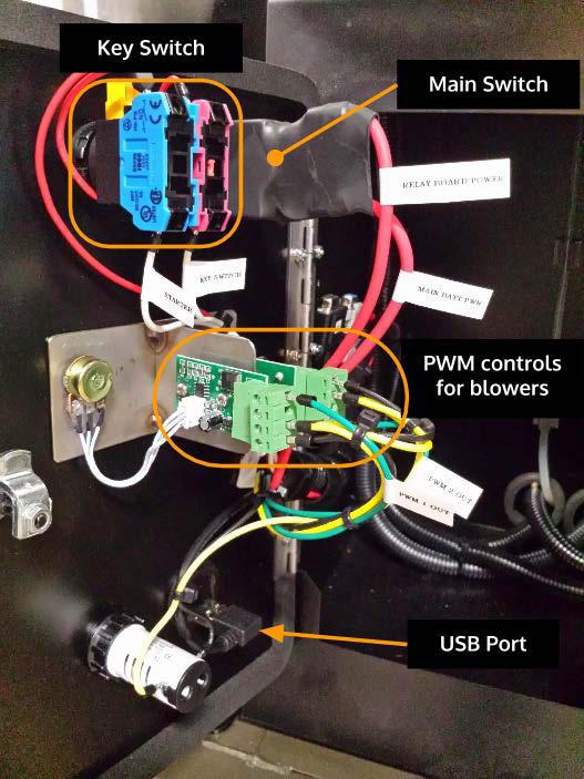
15 if you require detailed diagrams and pinouts, as the harnesses are consistently upgraded. 3.1 Main Power Switch A 30A breaker is used as the main power switch for the Power Pallet s automation system, providing protection from over-current events. When it is flipped up into the on position, it powers the automation assembly with 12V DC from the main battery. 3.2 Engine start key switch The engine start switch is a three position, spring return (OFF - ON - MOMENTARY) key switch, much like that in a typical car. The leftmost position is off. The switch is an input to the PCU and does not directly control any circuit: its functions are completely software defined. The on positions powers on the engine and governor, while the third momentary position starts the engine. 3.3 PWM blower controls The gas and air blowers are controlled by two pulse width modulation (PWM) circuits located on the back of the podium door and operated by dials on the front of the door. The PWMs send out a series of pulses, the duty cycle of which changes with the turning of the dial switches, providing signal on a continuum for smooth increase and decrease of blower speed. 3.4 USB Port The Universal Serial Bus (USB) port, labeled "PCU", is a serial connection that allows a computer to communicate with the PCU. The operator may use it to upload control code and to download and log run data. The outside port is a B-type female socket, so the operator will need the A-B male-male USB cable from the User Kit in order to connect his or her computer to the Power Pallet. It is important to keep the waterproof cap on the USB port when the connection is not in use in order to protect the connector against the elements and mechanical disturbance. Page 4-15
16 Page 4-16
BrewTroller Phoenix. Owners Manual. Updated - March 14, 2016 BREWTROLLER PHOENIX 1
 BrewTroller Phoenix Owners Manual Updated - March 14, 2016 BREWTROLLER PHOENIX 1 2016 BrewTroller All Rights Reserved. Product warranty or service will not be extended if: (1) the product is repaired,
Rover 5. Explorer kit
 Rover 5 Explorer kit The explorer kit provides the perfect interface between your Rover 5 chassis and your micro-controller with all the hardware you need so you can start programming right away. PCB Features:
Flamma BIOMASS COMBUSTION SYSTEM CONTROLLER. Preliminary Description V.1 Santi Moroño / Jose Caldelas / Juan R. Regueiro / 26/02/ :34
 Flamma BIOMASS COMBUSTION SYSTEM CONTROLLER Preliminary Description V.1 Santi Moroño / Jose Caldelas / Juan R. Regueiro 18-02-2013 / This document presents some preliminary ideas for the development of
GUIDE TO SP STARTER SHIELD (V3.0)
") OVERVIEW: The SP Starter shield provides a complete learning platform for beginners and newbies. The board is equipped with loads of sensors and components like relays, user button, LED, IR Remote and
OVERVIEW: The SP Starter shield provides a complete learning platform for beginners and newbies. The board is equipped with loads of sensors and components like relays, user button, LED, IR Remote and
Goal: We want to build an autonomous vehicle (robot)
") Goal: We want to build an autonomous vehicle (robot) This means it will have to think for itself, its going to need a brain Our robot s brain will be a tiny computer called a microcontroller Specifically
Goal: We want to build an autonomous vehicle (robot) This means it will have to think for itself, its going to need a brain Our robot s brain will be a tiny computer called a microcontroller Specifically
VCM Systems Vehicle Control Module Systems
 VCM Systems Vehicle Control Module Systems Technical Manual VCMS-SC (Standard Configuration) Switch Panel System The Model VCMS-SC Switch Panel System is a standard configuration of the VCMS product family
Arduino Uno. Arduino Uno R3 Front. Arduino Uno R2 Front
 Arduino Uno Arduino Uno R3 Front Arduino Uno R2 Front Arduino Uno SMD Arduino Uno R3 Back Arduino Uno Front Arduino Uno Back Overview The Arduino Uno is a microcontroller board based on the ATmega328 (datasheet).
keyestudio Keyestudio MEGA 2560 R3 Board
 Keyestudio MEGA 2560 R3 Board Introduction: Keyestudio Mega 2560 R3 is a microcontroller board based on the ATMEGA2560-16AU, fully compatible with ARDUINO MEGA 2560 REV3. It has 54 digital input/output
ARDUINO MEGA 2560 REV3 Code: A000067
 ARDUINO MEGA 2560 REV3 Code: A000067 The MEGA 2560 is designed for more complex projects. With 54 digital I/O pins, 16 analog inputs and a larger space for your sketch it is the recommended board for 3D
1. Carefully unpack the um260 s shipping carton and check the contents for damage.
 um260 Installation Manual um260 Installation Chapter 4 um260 MICRO MONITOR INSTALLATION This section of the um260 Micro Monitor Installation Manual describes the requirements and procedures for installing
ARDUINO MINI 05 Code: A000087
 ARDUINO MINI 05 Code: A000087 The Arduino Mini is a very compact version of the Arduino Nano without an on board USB to Serial connection The Arduino Mini 05 is a small microcontroller board originally
ARDUINO MEGA ADK REV3 Code: A000069
 ARDUINO MEGA ADK REV3 Code: A000069 OVERVIEW The Arduino MEGA ADK is a microcontroller board based on the ATmega2560. It has a USB host interface to connect with Android based phones, based on the MAX3421e
Manual 601: : USB/RS232. Specifications. Contents. Options
 Page 1 ATE-601 601: : USB/RS232 I/O Controller - 8 Inputs, 4/8 Relays The ATE-500/600 series is a range of modular I/O controllers. It uses small standardized boards which allows you to configure the system
Part Number N AEM 4-CH WIDEBAND UEGO CONTROLLER WITH NASCAR SPEC ECU CAN CONFIGURATION
 Part Number 30-2340-N AEM 4-CH WIDEBAND UEGO CONTROLLER WITH NASCAR SPEC ECU CAN CONFIGURATION FIGURE 1. WIRING DIAGRAM AEM 4 CH UEGO Controller Parts 1 x 35-2340 4 CH UEGO Module 1 x 35-2908 Wiring Harness
BLD04A Brushless DC Motor Driver
 BLD04A Brushless DC Motor Driver User s Manual V1.1 MAY 2011 Information contained in this publication regarding device applications and the like is intended through suggestion only and may be superseded
LH 700. Spare parts list. Forward and reversible plate. Valid from serial number. LH 700 Hatz Electric start 810 mm Bio
 Forward and reversible plate Hatz Electric start 0 mm Hatz Electric start 0 mm Bio Hatz Electric start mm Bio Valid from serial number 0000 0000 0000 Contents Contents General information.....................................................................................................................................
Thursday, September 15, electronic components
 electronic components a desktop computer relatively complex inside: screen (CRT) disk drive backup battery power supply connectors for: keyboard printer n more! Thursday, September 15, 2011 integrated
ELECTRICAL CONNECTORS ALL PRODUCTS
 ELECTRICAL CONNECTORS ALL PRODUCTS RENEWAL PARTS Supersedes: NOTHING Form 50.20-RP1 (103) LD08685 TABLE OF CONTENTS PAGE Single Line Micropanel...3 Optiview Panels...4 VSD's and Solid State Starters...5
J.BAUER Electronics. LaserBee I (T3D-T3N) 1 Watt HOBBYIST LASER POWER METER
 1 Watt HOBBYIST LASER POWER METER") J.BAUER Electronics (01/09) LaserBee I (T3D-T3N) 1 Watt HOBBYIST LASER POWER METER The LaserBee I 1 Watt (1000mW) Laser Power Meter was designed to enable the hobbyist technician to test higher power lasers
J.BAUER Electronics (01/09) LaserBee I (T3D-T3N) 1 Watt HOBBYIST LASER POWER METER The LaserBee I 1 Watt (1000mW) Laser Power Meter was designed to enable the hobbyist technician to test higher power lasers
Table of Contents. Table of Contents
 Table of Contents Table of Contents Introduction... 3 Installing a V Series Data Logger... 5 Getting acquainted with your V Series Logger System... 5 The Data Loggers... 5 The System Components... 6 Planning
CH1. Figure 1: M3 LOG Advanced
 TECHNICAL DOCUMENTATION 03/09/2003 GAUGE Notes: M3 LOG Advanced technical documentation, dimensions and pinout. Ver 1.05 M3 LOG Advanced Internal lateral accelerometer CH1 Beacon Speed COM Power CH2 CH3
Shack Clock kit. U3S Rev 2 PCB 1. Introduction
 Shack Clock kit U3S Rev 2 PCB 1. Introduction Thank you for purchasing the QRP Labs Shack Clock kit. This clock uses the Ultimate3S QRSS/WSPR kit hardware, but a different firmware version. It can be used
EMTRON AUSTRALIA EMTRON ECU OVERVIEW
 EMTRON AUSTRALIA EMTRON ECU OVERVIEW Table of Contents 1.0 General... 3 2.0 Injection... 4 3.0 Ignition... 5 4.0 Digital Inputs... 6 5.0 Auxiliary Outputs... 7 6.0 Analog Inputs... 9 7.0 Crank and Cam
Display & Log Unit. Mikael Larsmark. November 22, 2006
 Display & Log Unit Mikael Larsmark November 22, 2006 1 Contents 1 Introduction 3 2 Installation 4 2.1 Hardware.................................... 4 2.2 Software..................................... 4
LH 700. Spare parts list. Forward and reversible plate. Valid from serial number. LH 700 Hatz Electric start 810 mm Bio
 LH 00 Spare parts list Forward and reversible plate LH 00 Hatz Electric start 0 mm LH 00 Hatz Electric start 0 mm Bio LH 00 Hatz Electric start 0 mm LH 00 Hatz Electric start 0 mm Bio Valid from serial
MaxStepper Serial Step and Direction Pulse Generator. User Manual
 MaxStepper Serial Step and Direction Pulse Generator User Manual 2007 Kellyware 9/20/2007 WWW.KELLYWARE.COM Table of Contents Table of Contents... 2 Parts List... 3 Key Features... 3 Introduction... 4
IDUINO for maker s life. User Manual. For IDUINO Mega2560 Board(ST1026)
") User Manual For IDUINO Mega2560 Board(ST1026) 1.Overview 1.1 what is Arduino? Arduino is an open-source prototyping platform based on easy-to-use hardware and software. Arduino boards are able to read
User Manual For IDUINO Mega2560 Board(ST1026) 1.Overview 1.1 what is Arduino? Arduino is an open-source prototyping platform based on easy-to-use hardware and software. Arduino boards are able to read
An ISO 9001:2008 Registered Company
 An ISO 9001:2008 Registered Company Upfitter Interface Module The following list represents firmware v4.30 A-UIM4-506-A 2011-2016 Ford F250-550 B-UIM4-506-A 2017 F250-F550 A-UIM4-751-A 2013-2017 1500-5500
TT /12b INSTALLATION INSTRUCTIONS. Introduction
 TT-1545 11/12b INSTALLATION INSTRUCTIONS Original Issue Date: 6/10 Model: 20-300 kw Generator Sets Market: Industrial Subject: Decision-Maker 3000 Controller Service Replacement Kit GM75376 Introduction
AC300/AC400 SERIES DYNAMIC BRAKING and ADDITIONAL FORM C RELAY. INSTALLATION INSTRUCTIONS Document Number:
 Minarik Variable Speed AC Motor Drives AC300/AC400 SERIES DYNAMIC BRAKING and ADDITIONAL FORM C RELAY INSTALLATION INSTRUCTIONS Document Number: 250-0297 These instructions apply to models rated: 7.5 25
Makeblock Constructor I 3D Printer Kit. 2. 3D Printer Wiring Guide
 2. 3D Printer Wiring Guide 1 Content 2.1. Parts Required... 3 2.2 preparation... 7 2.2.1 Add heat sinks on the top of stepper motor driver chip... 7 2.2.2 Plug the jumper cap into corresponding position...
mxcontrol Multifunction Controller
 mxcontrol Multifunction Controller Data and event logging One controller hardware with dozens of configuration possibilities quickly downloaded via SD card (supplied) or via USB interface Type 8620 can
BMS: Installation Manual v2.x - Documentation
 Page 1 of 7 BMS: Installation Manual v2.x From Documentation This section describes how external peripheral devices are connected and additional functions of the BMS are used. I you have not done so already,
Shack Clock kit PCB Revision: QCU Rev 1 or QCU Rev 3
 1. Introduction Shack Clock kit PCB Revision: QCU Rev 1 or QCU Rev 3 Thank you for purchasing this QRP Labs Shack Clock kit. The kit uses the same PCB and bag of components as some other QRP Labs kits.
Bolt 18F2550 System Hardware Manual
 1 Bolt 18F2550 System Hardware Manual Index : 1. Overview 2. Technical specifications 3. Definition of pins in 18F2550 4. Block diagram 5. FLASH memory Bootloader programmer 6. Digital ports 6.1 Leds and
P522 Signal Processor
 P522 Signal Processor INSTALLATI INSTRUCTIS Self-Check Contact Ratings: Max switching power - 60 W 125Vac Max switching voltage - 220VDC, 250Vac Max switching current - 2A DC, AC Analog Flame Signal: User
HUB-ee BMD-S Arduino Proto Shield V1.1
 HUB-ee BMD-S Arduino Proto Shield V1.1 User guide and assembly instructions Document Version 0.5 Introduction & Board Guide 2 Schematic 3 Quick User Guide 4 Assembly Guide 6 Kit Contents 7 1) Diodes and
DC3IOB Revision User Guide Updated 7/12/12. Overview
 DC3IOB Revision 080910 User Guide Updated 7/12/12 Overview The DC3IOB is a three axis DC brush motor drive with an integrated PLC. A range of motor drive currents are selectable with jumper blocks. The
FX-2 Control Board ASY-360-XXX Setup and Configuration Guide
 FX-2 Control Board ASY-360-XXX Setup and Configuration Guide Micro Air Corporation Phone (609) 259-2636 124 Route 526. WWW.Microair.net Allentown NJ 08501 Fax (609) 259-6601 Table of Contents Introduction...
Start Relay Circuit - Test
 Start Relay Circuit - Test System Operation Description: Use this procedure to troubleshoot any suspect problems with the circuit for the start relay. This procedure covers the following diagnostic codes:
AC : INFRARED COMMUNICATIONS FOR CONTROLLING A ROBOT
 AC 2007-1527: INFRARED COMMUNICATIONS FOR CONTROLLING A ROBOT Ahad Nasab, Middle Tennessee State University SANTOSH KAPARTHI, Middle Tennessee State University American Society for Engineering Education,
ARDUINO UNO REV3 Code: A000066
 ARDUINO UNO REV3 Code: A000066 The UNO is the best board to get started with electronics and coding. If this is your first experience tinkering with the platform, the UNO is the most robust board you can
MTX-D Ethanol Content and Fuel Temperature Gauge User Manual
 MTX-D Ethanol Content and Fuel Temperature Gauge User Manual P/N 3912 kit does not include flex fuel sensor. The ECF-1 is compatible with GM P/Ns 13577429 and 13577379 1. Installation... 2 1.1 Gauge Mounting...
Adafruit Metro Mini. Created by lady ada. Last updated on :12:28 PM UTC
 Adafruit Metro Mini Created by lady ada Last updated on 2018-01-24 08:12:28 PM UTC Guide Contents Guide Contents Overview Pinouts USB & Serial converter Microcontroller & Crystal LEDs Power Pins & Regulators
FTC200 & FTA/FTX Quick Installation & Jumper Setting Guide
 FTC200 & FTA/FTX Quick Installation & Jumper Setting Guide Accuthermo Technology Corp. Safety Note Please read this entire document before you begin connecting cables and assembling your system Failure
D115 The Fast Optimal Servo Amplifier For Brush, Brushless, Voice Coil Servo Motors
 D115 The Fast Optimal Servo Amplifier For Brush, Brushless, Voice Coil Servo Motors Ron Boe 5/15/2014 This user guide details the servo drives capabilities and physical interfaces. Users will be able to
Board Of Education USB (#28850)
") 599 Menlo Drive, Suite 100 Rocklin, California 95765, USA Office: (916) 624-8333 Fax: (916) 624-8003 Sales: sales@parallax.com 1-888-512-1024 Tech Support: support@parallax.com 1-888-99-STAMP Web Site:
599 Menlo Drive, Suite 100 Rocklin, California 95765, USA Office: (916) 624-8333 Fax: (916) 624-8003 Sales: sales@parallax.com 1-888-512-1024 Tech Support: support@parallax.com 1-888-99-STAMP Web Site:
Manual. Specifications. Contents. Options
 Page 1 ATE-501: USB Input Controller - 8 Inputs The ATE-500/600 series is a range of modular I/O controllers. It uses small standardized boards which allows you to configure the system to your requirements.
Victor BB Comprehensive Guide Preliminary. Revision 1.3
 Preliminary Revision 1.3 Table of Contents 1. Purpose of this Guide... 3 2. Installing the Victor Dashboard... 5 2.1. Installing Serial Drivers... 7 2.1.1. Installing Serial Drivers Prolific PL2303...
UserGuide_TempSensor_with_Alarms Issue 4/
 SPECTECS TEMPERATURE SENSOR WITH ALARMS ( Wi-Fi enabled with optional module ) Embedded control EMC1001 sensor Range 0C to +125C Resolution 0.25C Accuracy +/-1.5C, 40 to 85C USB powered or external 2.2-16V
INTEGRATED SYSTEMS AND CONTROL, INC. User s Hardware Manual. PCMNET V 7. xx
 INTEGRATED SYSTEMS AND CONTROL, INC. User s Hardware Manual PCMNET V 7. xx INTEGRATED SYSTEMS AND CONTROLS, INC. PCMNET Users Manual Revised 2/4/2005 2003-2005 Integrated Systems and Control. Inc. PO Box
PCS Ferguson 8000 Series Overview Manual. The PCS Ferguson 8000 Series brand is trademarked by PCS Ferguson.
 The PCS Ferguson 8000 Series brand is trademarked by PCS Ferguson. These documents and materials are copyrighted by PCS Ferguson. 2016 All rights reserved. For information contact: PCS Ferguson 3771 Eureka
ARDUINO UNO REV3 SMD Code: A The board everybody gets started with, based on the ATmega328 (SMD).
.") ARDUINO UNO REV3 SMD Code: A000073 The board everybody gets started with, based on the ATmega328 (SMD). The Arduino Uno SMD R3 is a microcontroller board based on the ATmega328. It has 14 digital input/output
ARDUINO UNO REV3 SMD Code: A000073 The board everybody gets started with, based on the ATmega328 (SMD). The Arduino Uno SMD R3 is a microcontroller board based on the ATmega328. It has 14 digital input/output
Explorer V1.20. Features
 V1.20 Multi-function USB I/O Expander and Controller Features Dual h-bridge 1.3A motor drive with PWM speed control 4.6V to 10.8V input range USB communication 4x digital inputs 2x analogue inputs 7x 100mA
DX-10 tm Digital Interface User s Guide
 DX-10 tm Digital Interface User s Guide Serial Communications Revision C Copyright Component Engineering, All Rights Reserved Table of Contents Foreword... 2 Introduction... 3 What s in the Box... 3 What
Illustrated Parts List
 Illustrated Parts List SERIAL NUMBERS 730080-730074 ENGINE RELATED COMPONENTS... ENGINE RELATED COMPONENTS...3 ENGINE RELATED COMPONENTS...4 BASE, COVER... BASE, COVER... BASE, COVER...7 BASE, COVER...8
FX-2 Control Board ASY-360-XXX Setup and Configuration Guide
 FX-2 Control Board ASY-360-XXX Setup and Configuration Guide Micro Air Corporation Phone (609) 259-2636 124 Route 526. WWW.Microair.net Allentown NJ 08501 Fax (609) 259-6601 Table of Contents Introduction...
CAN-EGT by DIYAutoTune.com
 CAN-EGT by DIYAutoTune.com February 7, 2013 1 Introduction The first question you may have is, Why have a special board for EGT sensors? Many other sensors can be wired straight to a MegaSquirt, including
Darksoft s Sega ST-V Multicart
 Game selector for Darksoft s Sega ST-V Multicart Version 1.0 "1 Selector board Game selector board consists of Arduino Nano clone for the logic, two row LCD screen with buttons and main PCB with connectors
LO-LED64 Latched Output Card
 LO-LED64 Latched Output Card Product ID. : LO-LED64 Rev. : 1.00 Date : Nov 23, 2007 Firmware Rev. : N/A Beta Innovations (c) 2007 http://www.betainnovations.com Table of Contents Connecting the LO-LED64
Instruction Manual for BE-SP3 Circuit. 10/21/07
 Page 1 of 54 Instruction Manual for BE-SP3 Circuit. 10/21/07 Page 1 Index: Page 2 BE-SP3 Circuit Specifications. Page 3-4 Intro to the BE-SP3. Page 5 Basics of serial to parallel. Page 6-7 ASCII Code.
CODE 50108, 50110, 50164, 50165
 CODE 50108, 50110, 50164, 50165 ASSEMBLY PAGE NAME Machine Assembly Machine Assembly Machine Assembly (Wire feed chamber) Machine Assembly (Wire feed chamber) Feeding Unit Assembly CODE NO.: K NO.: FIGURE
Bosch LSU4 Wide Band UEGO Controller
 Bosch LSU4 Wide Band UEGO Controller Part Number 220-VM-AF1 CONFIGURATION Module Type: AF1 Serial Number: Output Units: Lambda A/F Gasoline A/F Methanol Channel Name: A/F Cyl 1 Channel Options: V_Net ID:
TA0139 USER MANUAL ARDUINO 2 WHEEL DRIVE WIRELESS BLUETOOTH ROBOT KIT
 TA0139 USER MANUAL ARDUINO 2 WHEEL DRIVE WIRELESS BLUETOOTH ROBOT KIT I Contents Overview TA0139... 1 Getting started: Arduino 2 Wheel Drive Wireless Bluetooth Robot Kit using Arduino UNO... 1 2.1. What
Innovation First, Inc Full-Size Robot Controller Reference Guide
 2004 Full-Size Robot Controller Reference Guide 2.19.2004 www.innovationfirst.com Page 2 Table of Contents 1. Robot Controller Overview... 3 2. Main Power Input... 4 3. Battery Backup Power... 4 4. PROGRAM...
ARDUINO LEONARDO WITH HEADERS Code: A000057
 ARDUINO LEONARDO WITH HEADERS Code: A000057 Similar to an Arduino UNO, can be recognized by computer as a mouse or keyboard. The Arduino Leonardo is a microcontroller board based on the ATmega32u4 (datasheet).
Connecting a Cisco Output Module
 CHAPTER 5 Overview The optional Cisco Output Module (Figure 5-1) is attached to a Cisco Physical Access Gateway or Cisco Reader Module to provide additional connections for up to 8 outputs, each of which
Arduino ADK Rev.3 Board A000069
 Arduino ADK Rev.3 Board A000069 Overview The Arduino ADK is a microcontroller board based on the ATmega2560 (datasheet). It has a USB host interface to connect with Android based phones, based on the MAX3421e
DC3IOB Revision User Guide Updated 3/29/10. Overview
 Revision 080910 User Guide Updated 3/29/10 Overview The is a three axis DC brush motor drive with an integrated PLC. A range of motor drive currents are selectable with jumper blocks. The integrated PLC
Thank you for purchasing the RGB Multi-MCU base and driver board from SuperTech-IT and TheLEDCube.com
 CONGRATULATIONS Thank you for purchasing the RGB Multi-MCU base and driver board from SuperTech-IT and TheLEDCube.com In this document, MCU means Microcontroller such as the PIC32, ATmega328P, prototype
Unit 2. Computer Control. PIC stands for PROGRAMMABLE INTERFACE CONTROLLER. A PIC chip takes in input signals and then controls output transducers
 Unit 2 Computer Control PIC stands for PROGRAMMABLE INTERFACE CONTROLLER A PIC chip takes in input signals and then controls output transducers Name: Form: 2 ASIC or Application Specific Integrated Circuits
Building and using JasperMIDI
 Building and using JasperMIDI Table of Contents Introduction... Bill Of Materials... 2 Building Choices... 3 Construction... 4 Installing in a Jasper enclosure... 5 Standalone use... 6 Using JasperMIDI...
Circuit Diagram For Water Level Controller Using 8051 Microcontroller With Pin Configuration
 Circuit Diagram For Water Level Controller Using 8051 Microcontroller With Pin Configuration This is the circuit diagram water level controller using microcontroller Free diagram for water level controller
IS-S0108 Single Switch Solution
 IS-S0108 Single Switch Solution IS-S0108 Single Switch Solution Revision D NKK SWITCHES 7850 E. Gelding Drive Scottsdale, AZ 85260 Toll Free 1-877-2BUYNKK (877-228-9655) Phone 480-991-0942 Fax 480-998-1435
MP6500 Stepper Motor Driver, Digital Current Control
 This breakout board for the MPS MP6500 micro stepping bipolar stepper motor driver is Pololu s latest stepper motor driver. The module has a pinout and interface that are very similar to that of our popular
TECHNICAL PRODUCT DATASHEET
 FORM-ENG-0018 REV A 06-02-03 ISO 9001 CERTIFIED Phone: (352) 629-5020 or 800-533-3569 Fax: (352)-629-2902 SUITABLE FOR EXTERNAL DISTRIBUTION TECHNICAL PRODUCT DATASHEET ES-Key Climate Control Module P/N
PHASED OUT PRODUCT DC2. Microcontroller DESCRIPTION FEATURES ORDERING INFORMATION. BLN Issued: June 1995
 DESCRIPTION DC2 Microcontroller Danfoss DC2 Microcontroller is a multi-loop controller that is environmentally hardened for mobile off-highway control system applications. The DC2 Microcontroller has the
General-Purpose Microcontroller Module 12a Hardware Reference Release 1.4a (October 11, 2017)
") General-Purpose Microcontroller Module 12a Hardware Reference 1 General-Purpose Microcontroller Module 12a Hardware Reference Release 1.4a (October 11, 2017) Purpose: General-purpose platform to accommodate
General-Purpose Microcontroller Module 12a Hardware Reference 1 General-Purpose Microcontroller Module 12a Hardware Reference Release 1.4a (October 11, 2017) Purpose: General-purpose platform to accommodate
VERSION 1.1 SEPTEMBER 12, 2017 ULTIMATE POWERBOX PRODUCT MANUAL BY PEGASUS ASTRO [COMPANY ADDRESS]
![VERSION 1.1 SEPTEMBER 12, 2017 ULTIMATE POWERBOX PRODUCT MANUAL BY PEGASUS ASTRO [COMPANY ADDRESS]](/thumbs/82/85874861.jpg "VERSION 1.1 SEPTEMBER 12, 2017 ULTIMATE POWERBOX PRODUCT MANUAL BY PEGASUS ASTRO [COMPANY ADDRESS]") VERSION 1.1 SEPTEMBER 12, 2017 ULTIMATE POWERBOX PRODUCT MANUAL BY PEGASUS ASTRO [COMPANY ADDRESS] INTRO Thank you for purchasing our Pegasus Astro - Ultimate Powerbox. If you are tired of carrying multiple
VERSION 1.1 SEPTEMBER 12, 2017 ULTIMATE POWERBOX PRODUCT MANUAL BY PEGASUS ASTRO [COMPANY ADDRESS] INTRO Thank you for purchasing our Pegasus Astro - Ultimate Powerbox. If you are tired of carrying multiple
RoboClaw 2x30A Dual Channel Motor Controller
 RoboClaw 2x30A, 34VDC Dual Channel Brushed DC Motor Controller Version 2.2 (c) 2016 Ion Motion Control. All Rights Reserved. Feature Overview: 60 Amps Peak Per Channel Channel Bridging Supported Dual Quadrature
Prototyping Module Datasheet
 Prototyping Module Datasheet Part Numbers: MPROTO100 rev 002 Zenseio LLC Updated: September 2016 Table of Contents Table of Contents Functional description PROTOTYPING MODULE OVERVIEW FEATURES BLOCK DIAGRAM
HARDWARE OPERATIONS MANUAL
 HARDWARE OPERATIONS MANUAL Table of Contents INTRODUCTION... 2 SECTION 1: HARDWARE COMPONENT ASSEMBLIES... 2 MECHANICAL HARDWARE AND CASE... 2 PCB ASSEMBLY... 4 ISD RECORDING CIRCUIT... 5 BREADBOARD ASSEMBLY...
2. Site Planning lists the prerequisites and physical requirements for installing the 289H M LSS monitor.
 289H M LSS Installation & Operations Manual Overview Section 1 INTRODUCTION This manual provides procedures for installing and operating the 289H M Loop Surveillance System (LSS) monitor. It addresses
IDUINO for maker s life. User Manual. For IDUINO development Board.
 User Manual For IDUINO development Board 1.Overview 1.1 what is Arduino? Arduino is an open-source prototyping platform based on easy-to-use hardware and software. Arduino boards are able to read inputs
Schematic Diagram: R2,R3,R4,R7 are ¼ Watt; R5,R6 are 220 Ohm ½ Watt (or two 470 Ohm ¼ Watt in parallel)
") Nano DDS VFO Rev_2 Assembly Manual Farrukh Zia, K2ZIA, 2016_0130 Featured in ARRL QST March 2016 Issue Nano DDS VFO is a modification of the original VFO design in Arduino Projects for Amateur Radio by
Nano DDS VFO Rev_2 Assembly Manual Farrukh Zia, K2ZIA, 2016_0130 Featured in ARRL QST March 2016 Issue Nano DDS VFO is a modification of the original VFO design in Arduino Projects for Amateur Radio by
MAVRIC-IIB Mega AVR Integrated Controller II Revision B Technical Manual
 MAVRIC-IIB Mega AVR Integrated Controller II Revision B Technical Manual BDMICRO http://www.bdmicro.com/ March 28, 2005 Copyright (c) 2004 BDMICRO All Rights Reserved. MAVRIC-IIB Technical Manual March
UNIVERSAL MOTION INTERFACE (UMI) ACCESSORY
 ACCESSORY") USER GUIDE UNIVERSAL MOTION INTERFACE (UMI) ACCESSORY Introduction This user guide describes how to use the UMI-A, UMI-Flex, and UMI-Flex accessories. The UMI products are connectivity accessories you
USER GUIDE UNIVERSAL MOTION INTERFACE (UMI) ACCESSORY Introduction This user guide describes how to use the UMI-A, UMI-Flex, and UMI-Flex accessories. The UMI products are connectivity accessories you
Seven Channel Remote Control
 Seven Channel Remote Control Page 1 Versa7 Kit Contents The Versa7 is designed to remotely control up to seven devices, or functions. All seven functions can be controlled with the supplied four button
Manual# Installation Manual. 200E Series. DCU 210E/208E Engine Panel RP 210E/220E Remote Panel
 Manual# 1006495 Installation Manual 200E Series DCU 210E/208E Engine Panel RP 210E/220E Remote Panel Installation Manual for the Marine Pro 200E Series ~~~ DCU 210E/208E Diesel Engine Control Unit RP 210E/220E
This is an inspection failure, not meeting the requirement of >10k Ohm between either PD battery post and chassis.
 Troubleshooting This is a document put together by CSA Laura Rhodes that contains a lot of information about troubleshooting steps for a lot of common control system problems encountered at events. No
USER MANUAL UPDATED
 USER MANUAL UPDATED 4-19-18 Thank you for purchasing the CAN-EGT interface! Monitoring exhaust gas temperatures in real time, cylinder-by-cylinder, means more accurate air-fuel targets, prevention of catastrophic
Temperature Programming Quick Reference Guide
 Temperature Programming Quick Reference Guide Normal Mode Dial Brightness (press one at a time) Peak Mode Factory Default Reset (Hold for 5 seconds) High Alert Setting Mode Use LEFT or RIGHT buttons to
Energy Meter and. Current Transducer. Assembly Manual
 Energy Meter and Current Transducer Assembly Manual 2017 1 The energy meter assembly is made of two separate boxes and associated accessories, as follows: Energy Meter (EM) Box, with two cables feeding
MicroTech III Water Source Heat Pump BACnet MS/TP Communication Module
 Installation and Maintenance Manual IM 928- Group: Controls Part Number: 66920770 Date: July 2009 Supersedes: IM 928 MicroTech III Water Source Heat Pump BACnet MS/TP Communication Module NOTICE Use this
DirectCommand Installation CASE IH SPX Ag Leader Technology. PN: Rev. E January 2014 Page 1 of 19
 Note: These installation instructions only cover installation on SPX 4420 Sprayers only. For installation on SPX 3230/3330 Sprayers refer to Installation Instructions P/N 2005945. For SPX 4430 refer to
e-ask electronic Access Security Keyless-entry OEM / Dealer / Installer Cargo Lock / Unlock Version Installation & Instructions (UM04 ~ )
") e-ask electronic Access Security Keyless-entry OEM / Dealer / Installer Cargo Lock / Unlock Version Installation & Instructions (UM04 ~ 18990-04) Table of Contents Introduction... 1 e-fob Operation and
e-ask electronic Access Security Keyless-entry OEM / Dealer / Installer Cargo Lock / Unlock Version Installation & Instructions (UM04 ~ 18990-04) Table of Contents Introduction... 1 e-fob Operation and
How-To #3: Make and Use a Motor Controller Shield
 How-To #3: Make and Use a Motor Controller Shield The Arduino single-board computer can be used to control servos and motors. But sometimes more current is required than the Arduino can provide, either
Abstract. GLV User Manual 1
 GLV User Manual 1 Abstract This user manual is a high level document that explains all operational procedures and techniques needed to operate the GLV system in a safe and effective manner. Anyone operating
Secured Series: Hub Plus Kit Single Door Controller Package Installation Manual
 Secured Series: Hub Plus Kit Single Door Controller Package Installation Manual This package is designed to simplify the connections to our Secured Series Hub Plus Controller. This will translate into
MegaPi Born to Motion Control
 MegaPi Born to Motion Control SKU: 10050 Weight: 130.00 Gram 1. Overview MegaPi is a main control board specially designed for makers and also an ideal option for being applied to education field and all