J2 630 Integrated Touchscreen Computer. System Manual
|
|
|
- Arron Maxwell
- 6 years ago
- Views:
Transcription

1 J2 630 Integrated Touchscreen Computer System Manual December 2010
2 Copyright 2010 J2 Retail Systems Change history Version 1.0 Release December 2, 2010 Version 1.1 change power usage number to match testing and add IEA One Watt Initiative statement. 2
3 3
4 Contents Overview... 6 Specifications... 8 System Front View Rear View I/O Ports Atom Processor System Memory On /Off Button Hard Disk Drive / Solid State Drive Touch Screen System Board LCD Display Secondary Display Port USB ports Ethernet Connection Serial ports Audio Cash Drawer Port CMOS Reset Mini PCI-E Power Supply Typical Power Consumption Packing List Standard Items System Installation Counter Top Base VESA Mounting Wall Mount Bracket Installation MSR Installation SSD/HHD Access Removing the Power Supply Adaptor BIOS Settings Starting the BIOS Setup BIOS Menus Main, System Overview Advanced Settings SATA Configuration Super I/O Configuration Hardware Health Status
5 Power Option Power Configuration COM/VGA Ports USB Configuration LCD Brightness Control High Performance Event Time Display OEM Logo Wake On LAN Boot Settings Exit Options Driver Installation Driver Download Additional Drivers/Utilities Optional Items Customer Display Option Connecting the Cable for a J2 630/615/580 customer display Dip Switch and Software Setting J2 630/615/580 UPS Specifications Hardware Software Setup in XP Status LED
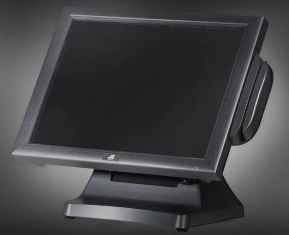
6 Overview Featuring the Intel 1.8GHz Atom D525 Dual Core processor and Intel chipset the new J2 630 computer provides dual core performance and a low cost. Designed with reliability and durability in mind it incorporates a 160GB 2.5 inch SATA Hard drive and 1GB of DDR3 memory as standard with Fanless convection cooling. Using an ELO touch controller as well as an ELO resistive touch screen the 630 provides unmatched touch responsiveness and reliability. For extremely high transaction applications an IR and SAW touch screen version is also available, known in the industry because they have no known wear out mechanism. Full featured I/O ports include four serial, one parallel, five USB, a one gigabit Ethernet, secondary video and a dual cash drawer port. The J2 630 does not compromise quality and provides one of the most cost effective integrated touch screen computer solutions available in the market today. It supports all Microsoft Windows operating systems, including Windows 7, Windows 7 Embedded, Windows XP Pro for Embedded Systems, XP Pro, Windows XP Embedded, POSReady 2009, WEPOS, Windows CE 6.0 plus MS- DOS and Linux. The all in the head design means that the J2 630 can serve as a counter top, or as a wall or a pole mounted unit all in the same computer. With the standard counter top base, VESA mounting points and optional wall mount brackets, the versatile 630 can fit numerous touch screen applications. The small footprint with the 15-inch LCD display is particularly compact and makes it ideal for the space conscious retailer. The front swipe MSR can be mounted side by side and fits easily in narrow niches. Using the new Intel 1.8GHz Atom D525 processor with integrated graphics and memory controller, 2 processor cores, 4 execution threads, 1MB of cache and use of up to 4GB of DDR3 memory and Intel ICH8M I/O chipset the J2 630 computer is the ultimate system to handle Windows 7 POS applications at a low cost. J2 630 Intrgrated Touch Screen Computer 6
7 7
8 Specifications Main board Processor Intel D GHz Dual Core Atom processor Chipset Atom D525 (Pineview) Graphics/Memory, ICH8M I/O chipset System Memory Two SO-DIMM DDR3-800 Sockets, 1GB Standard, 4 GB optional LCD Touch Panel LCD Size Brightness 15 TFT LCD 250 nits, Adjustable Resolution 1024 x 768 Touch Screen ELO Resistive 5-wire or optional ELO Infrared (IR) or SAW Tilt Angle 0 ~ 100 Mounting Storage Counter top base and VESA standard SSD or HDD 160GB SATA HDD Standard, SSD optional, 8GB/16GB/32GB + Expansion Mini-PCI-E Slot External I/O Ports USB SERIAL LAN One, normally used for an internal n wireless card 5 USB 2.0 ports. 4 USB located in the cable well, one side unit 4 Serial Ports, RJ 45, 3 RJ45 to DB9 and 1 RJ45 to DB25 adapters included, Power on serial ports 3,4 BIOS enabled (+12V or +5V) One Gigabit, RJ45 in cable well (Realtek RTL8111) 2 nd VGA Optional +12V Power, BIOS enabled, up to 2048 x 1536 Cash Drawer DC Jack Audio Jack Front I/O Indicator Power LED Power Power Adaptor Optional Peripheral MSR ibutton Biometrics WIFI RJ 11 (24V or 12V) with status, can support two cash drawers Power in, 19VDC 4.74 amps Microphone in, headset out Green - for system power on 19VDC, 95W, VAC, 1.8A MAX 3 Track (on PS2 port, wedge type) Dallas Key ibutton/msr (on PS2 port, wedge type) or ibutton only MSR/Finger Print Reader (Digital Persona) or Finger Print Reader only Optional internal n (a/b/g compatible) wireless LAN 8
9 Second Display Customer Display UPS Mounting 10.4" or 12 Second LCD display, with or without touch, powered from the J2 630 Customer Side VFD display with 2 x20 characters, powered from hour DC UPS, mounts in base of unit Standard Counter Top Base, Adjustable Viewing Angle Optional Optional Environment EMC & Safety Operating Temperature Storage Temperature Operating Humidity Storage Humidity Dimensions (W x D x H) Weight OS Support Wall Mount /VESA Mount Bracket Optional adjustable angle VESA/Wall Mount Bracket FCC, Class A, CE, LVD 0 ~ ~ 55 20% ~ 80% RH non-condensing 20% ~ 85% RH non-condensing 370 x 250 x 340mm 7.45kg Windows 7, Windows 7 Embedded, XP Pro for Embedded, POSReady 2009, XP Embedded Standard, WEPOS, CE 6.0, Linux, DOS * This specification is subject to change without prior notice. 9

10 System The J2 630 uses the same dynamic design as the J2 580, J2 615 and J2 650 computers. This allows for different systems to be integrated at the same customer site, maintaining a well balanced look and feel for your important installations. All Peripherals are the same as used on the J2 580 and J Front View MSR Rear View Power LED HDD/SSD Module I/O Ports ON/OFF BUTTON 10
11 I/O Ports The J2 630 has an integrated design with all the electronics in the head. I/O ports are accessible in the cable well at the bottom of the unit (please see below): OFF/ON BUTTON COM 1, 2, 3, 4 Headset out Mic In LAN Parallel USB VGA Cash Drawer Drawer DC-IN Atom Processor The J2 630 uses the Intel Atom D525 dual core processor which only requires 13 watts of power and incorporates the north bridge of the chipset as well. With a speed of 1.8GHz, a 1MB second level cache as well as a memory speed of 800MHz, the J2 630 provides the performance necessary for thin as well as most thick POS software applications with enough horse power to run Windows 7. With the graphic and memory controller intergraded on the same die as the processor the Intel Atom D525 processor provides excellent video performance and is more than capable of running a secondary monitor with full screen video at high resolution in addition to running a POS application. System Memory The J2 630 comes standard with 1GB of DDR3-800 of memory. The system has two memory sockets and uses SO-DIMM DDR3-800 type memory. The unit supports a maximum of 4GB of memory. Additional memory can be added in just one or two minutes using the slide in / out feature of the system board to access the memory sockets. On /Off Button The On/Off button is located in the cable well, as shown above. This button is located especially to prevent accidental powering down by the user. The function of the button can be controlled by the OS. Should the J2 630 hang for some reason, note that it can always be powered off by holding the On / Off button in for four seconds. The J2 630 also supports the following: Restore to Former states, On or Off if AC power loss, Wake On LAN, and Wake On RTC alarm features control the system s power up. Wake On LAN is enabled by default and the other options are set in the BIOS. 11
12 Hard Disk Drive / Solid State Drive The J2 630 has one drive bay that supports a 2.5 inch SATA HDD or SDD. The standard drive supplied is a 160GB SATA 3.0Gb/s HDD. The SSD or HDD can be accessed simply by loosening the one screw on the drive bay panel on the right side of the unit. The drive can now easily be slid into or out of the drive bay. SSD/HDD Access In addition to the standard 160GB SATA 2.5 inch HDD, J2 offers SSD drives in 8GB, 16 GB and 32GB sizes for the J Higher capacities are also available if required. As a special ordered item the J2 630 can be shipped with and internally mounted SSD with a size of 8/16/32/64GB. The standard slide in / out HHD/SSD is still support to form a two drive system. Touch Screen The J2 630 uses an ELO touch screen controller paired with the ELO five-wire touch screen rated at 35 million touches per point. As with all J2 designed products using resistive touch screens, the 630 unit includes a water tight gasket for spill resistance. The ELO Infrared (IR) and SAW touch screen is also available for the J2 630 as an option. The IR and SAW touch screen have no known failure mode-- it does not wear out. With a protective cover over the LCD panel the IR and SAW touch screen does not reduce LCD panel brightness. When operating in a very high usage environment the IR or SAW is the recommended touch screen technology. Depending on operating environments and usage, both Resistive, IR and SAW touch screens have their strengths and weaknesses. Resistive touch screens are by far the most responsive while IR and SAW touch screens are the most durable. J2 offers all three touch screen technologies on the 630 (and 615) computer. 12

13 System Board POS computers typically have a desired life span of 10 years or longer therefore product quality is of the utmost importance. J2 630 electronics are built with high end components to ensure reliability and long lasting product performance. The slide in / out design of the J2 630 system board makes for easy memory upgrades of servicing if every needed. The system board can be swapped out in less than one minute. J2 630 System Board Quick Change System Board 13
14 LCD Display The LCD display for the J2 630 computer is a 1024 x 768 resolution display with 16.2 Million colors. The brightness is rated at 250cd/m 2. The Intel controller allows for the display to be rotated to 0, 90, 180 or 270 degrees without any loss of performance. Secondary Display Port A secondary video display is supported on the J2 630 and can be set as the primary or secondary display. Secondary video displays can be configured as a Twin, Intel Dual Display Clone or Extended Desktop. Most all monitor resolutions, from 640 x 480 to 2048 x 1536, are supported via the Secondary Display Port. The secondary display can also be rotated at 90, 180 or 270 degrees. A number of additional features are supported depending on the capabilities of the monitor. Secondary Display Port The Secondary Display Port has an industry standard HD DB15 connector. When using a J2 supplied 10.4 or a 12 secondary LCD monitor, the monitor can be powered from the J A BIOS setting, as shown below, enables +12V supplied through the VGA. Warning: The +12V VGA power should only be enable for J2 supplied monitors and could damage non-powered enabled monitors. Please check with J2 if in doubt. 14
15 USB ports The J2 630 has five external and two internal USB 2.0 ports. The four external ports are located in the cable well and one on the side of the unit. In addition there are two internal USB ports used as follows: one is used for the optional Finger Print Reader and is located on the MSR connecting point; the second internal USB port is used for the IR touch screen controller in the IR and SAW version of the 630 unit. USB Ports Ethernet Connection The J2 630 uses the Realtek 8111 Gigabit Ethernet controller. The Ethernet connector is located in the cable well (shown below). The Ethernet controller supports Wake On LAN, the BIOS supports a PXE and RPL Boot ROMs as well. Ethernet Port 15

16 Serial ports The 630 unit has four external RS232 serial ports, two of which can be powered; COM3 and COM4. The serial ports use a ten pin RJ45 connector. The unit comes standard with two serial cables, three RJ45 to DB9 adapter cables and a 5 foot RJ45 to DB25 serial printer cable that works with EPSON and EPSON compatible printers. Additional cable adaptors can be order from J2. Both serial (COM) ports 3 and 4 can be BIOS enabled to provide power to external devices. The J2 630 is shipped standard with serial 3 & 4 strapped to supply +12V to pin 9 of the DB9 connector if enabled in the BIOS. Serial ports 3 and 4 can have jumpers set to select for either +12 volts or +5 volts. J2 does not recommend using +5 volts devices if it can be avoided, as it is quite easy to damage a +5 volt device by plugging it into a port supplying +12 volts. Most all serial scanners are available in the + 12 volt version. If a +5 volt device is used, it is recommended that it is clearly marked as such. The maximum current is 500ma and is over-current protected. Port Voltage JP18 +5V * +12V V * +12V COM3 COM4 * Factory Default +12 V JP18 Location Pin 1 16
17 Serial Ports BIOS Setting Serial Port(s) Power Enable 17
18 RJ45 to DB9 J2 Adaptor Cable Pin-Out 8 pin adaptor when using CAT5/6 cable RJ45-10 Pin DB9 Signal RJ45-8 Pin DB9 Signal Pin Pin 2 Pin 1 DCD Pin 1 Pin 1 DCD Pin 3 Pin 6 DSR Pin 2 Pin 6 DSR Pin 4 Pin 2 RD Pin 3 Pin 2 RD Pin 5 Pin 7 RTS Pin 4 Pin 7 RTS Pin 6 Pin 3 SD Pin 5 Pin 3 SD Pin 7 Pin 8 CTS Pin 6 Pin 8 CTS Pin 8 Pin 4 DTR Pin 7 Pin 4 DTR Pin 9 Pin 5 GND Pin 8 Pin 5 GND Pin 10 Pin 9 RI The J2 Cable Adaptor (supplied) RJ45 to DB25 J2 Serial Pinter Cable Pin-out when using 8 wire CAT5/6 cable RJ45-10 Pin Signal DB25 Signal RJ45-8 Pin Signal DB25 Signal Pin Pin 2 DCD Pin 1 DCD Pin 3 DSR Pin 20 DTR Pin 2 DSR Pin 20 DTR Pin 4 RD Pin 2 SD Pin 3 RD Pin 2 SD Pin 5 RTS Pin 5 CTS Pin 4 RTS Pin 5 CTS Pin 6 SD Pin 3 RD Pin 5 SD Pin 3 RD Pin 7 CTS Pin 4 RTS Pin 6 CTS Pin 4 RTS Pin 8 DTR Pin 6 DSR Pin 7 DTR Pin 6 DSR Pin 9 GND Pin 7 GND Pin 8 GND Pin 7 GND Pin Epson or Epson compatible serial printer cable 18
19 Audio The J2 630 uses the Realtek HD audio CODEC and has two internal speakers. In addition there is a microphone in and headset out auto jack on the cable well as shown below. The Pink Jack is for the microphone and the Green is for the headset. Audio Microphone in and Headset out Cash Drawer Port The 630 has one cash drawer port that can support one cash drawer directly, or two cash drawers when using a Y splitter cable. The Y splitter cable is the same type as would be used with an EPSON printer. The port is located in the cable well and uses the industry standard RJ-11 connector and pin out (illustrated below). Cash Drawer Cash Drawer Pin Assignment 6 1 Pin Signal 1 GND 2 CD 1 SOLENOID 3 STATUS 4 12V / 24V 5 CD 2 SOLENOID 6 GND 19
20 The application may address the Cash Drawer port in a number of ways. They are: 1) Using the J2 supplied OPOS drivers for Windows 7, XP Pro, POSReady and XP Embedded. 2) Using the J2 supplied Virtual COM port for CE.NET, Windows 7, XP Pro, POSReady and XPE 3) Direct access to the I/O ports: The Virtual COM port driver that is standard on Windows XP Pro, WEPOS and XP embedded maps the cash drawers to COM 6 and COM7. These COM port numbers can be changed by modifying using the J2 virtual port configuration utility. A reboot will be needed for these changes to take effect. To open Cash Drawer One: Send a bell character to the COM6 serial port. (The bell character is the ASCII 07 hex character Control G. ) To open Cash Drawer Two: Send a bell character to the COM7 serial port. The open/close status of the drawer may be obtained by reading the status bits of its COM port. The drawer open/close status will be reflected on the CTS and RI bits, either bit may be used. This virtual COM port driver is designed to work the same as serial cash drawers and will work with drivers for serial cash drawers. The Virtual COM port driver that is standard on Windows CE.NET and the cash drawer appears as COM6. To open Cash Drawer One: Send a bell character to the COM6 serial port. (The bell character is the ASCII 07 hex character Control G. ) To open Cash Drawer Two: Send an ESC character, then a bell character to the COM6 serial port. The open/close status of the drawer may be obtained by reading the status bits of COM6, and the drawer open/close status will be reflected on the CTS and RI bits, either bit may be used. The OPOS drivers, Virtual Port drivers and a Cash drawer test program may be downloaded from the J2 web site: The cash drawer can be directly accessed through an I/O port, 48C hex. By outputting the correct value to the port cash drawer one or two can be fired and the cash drawer status can be read on the same port. The cash drawer solenoid should only be turned on for a maximum of 100ms. Also note that cash drawer one and two solenoids should never be turned on at the same time. 20
 are closed or not attached CMOS Reset If it becomes necessary the CMOS memory can")
21 Cash drawer I/O port Port 0x48C Value sent/returned Action Value 0x08 Write 0x08 Turn on Solenoid Cash Drawer 1 Value 0x04 Write 0x04 Turn on Solenoid Cash Drawer 1 Value 0x00 Write 0x00 Turn off Solenoid Cash Drawer 1&2 Mask 0x40 Read bit 6 zero Cash Drawer 1 or 2 is open Mask 0x40 Read bit 6 one Cash Drawer(s) are closed or not attached CMOS Reset If it becomes necessary the CMOS memory can be reset to factory defaults by adding the CMOS reset jumper JP1 for a few seconds and then removing it. This would normally only be needed to clear an unknown password from CMOS otherwise the normal BIOS load defaults function could be used. JP1 Location 21

22 Mini PCI-E The onboard Mini PCI Express connector is normally used for the optional internal n wireless LAN card. Mounting Screw 22

23 Power Supply The J2 630 uses a 95 watt notebook type power supply that is normally mounted in the base of the unit. The power supply is rated with an output of 19 VDC 4.74 Amps and has an input rating of VAC at 50~60Hz 1.4 Amps maximum. The power supply typically has an efficiency rating of 85% under light loads, with a 90% or better rating under heavy loading. The power supply connector is a four pin locking type that plugs into the system power input connector which is located in the cable well. The power supply has most all worldwide safety ratings. Please refer to the power supply itself for the list covered. The J2 630 is classified according to safety regulations as a low voltage device with the safety rating of the power supply being the one required. Power Input connector Power Supply Mounting in Base 23
24 Typical Power Consumption 630 The typical power consumption of the 630 is much lower that a desktop computer and more comparable to a notebook computer. Using the Intel s Atom processors and Intel chipset allows for much lower power consumption than previous generations of POS computers. This, when coupled with J2 software power reduction utilities, can greatly reduce the system s total carbon foot print. Test conditions Voltage: 220VAC 50Hz, measured voltage 240VAC OS: Windows 7 Heavy Load Program: PassMark Burn-In Test Temperature: 27c Updated: December 1, 2010 All systems where tested in their standard hard drive configuration. Results are +/- 15%. J GHz Atom with 1GB Memory, 8GB SSD 1: Normal application including most POS software 35 watts 2: Boot up 38 watts 3: Very heavy load application 40 watts 4: Normal POS application, back light off 20 watts 5: Standby, unit off, waiting for wake on LAN, RTC or power button 0.5 watts The J2 630 wall adapter conforms to the IEA One Watt Initiative and consumes less than 0.5 watt when the unit is in standby. 24
 AC power cord 4: Printer Cable 3: COM Cable (1) 25")
25 Packing List The following contents should be found in the carton: 1: System 2: AC Power cord 3: Three Serial RJ45 to DB9 Adaptor 4: One Serial Printer Cable Standard Items 1: System with (2:) AC power cord 4: Printer Cable 3: COM Cable (1) 25
26 System Installation Counter Top Base The J2 630 is shipped with a counter top base which allows for the head to be adjusted from To remove the integrated head from the base, loosen the thumbscrew located on the back of the unit under the hinge of the counter top base, as shown below. Then lift the head as illustrated: a. Loosen the thumbscrew (1) b. Lift the panel up and separate it from the stand bracket 26
: a.")

27 To mount the J2 630 to the base, do the reverse (as shown below): a. attach the panel to the desk mount hinge bracket and slide it into the position, as shown by the red arrows b. Tighten the thumbscrew to finish the installation 27

28 VESA Mounting The four base mounting bracket screws can be remove and these mounting point may be used with most 75mm VESA mounting brackets. VESA Mounting Points 28


29 Wall Mount Bracket Installation The wall mount bracket has threaded mounting holes (screws provided) for the 75mm VESA standard; and unthreaded holes for the 100mm standard. Using the 100mm hole pattern the bracket can be used by itself as a wall mount bracket. After installing the thumbscrew clip mount bracket to the wall, hang the J2 630 on the bracket. Install screw to secure thumbscrew clip The bracket slides on to the J2 630 mount posts, as shown. Normally the bracket would already be mounted to the wall or a VESA mount and the 630 would be hung on the bracket. Once in place the thumb screw would be tightened. 29


30 MSR Installation a. Remove the 2 screws b. Connect the cable. c. Slide the MSR into the position and tighten the screws to finish the installation. Be careful not to pitch the cable when installing. 30

")
31 SSD/HHD Access Loosen the screw Slide the SSD/HDD Module (as shown) 31
32 Removing the Power Supply Adaptor Remove the two screws to release the adaptor and the bracket. 32

 Pull the handle in the")

33 Replacing the Mother Board Loosen the two thumbscrews (you may require a screw driver) Pull the handle in the direction as shown order to release the mainboard tray from the system 33
. Press DEL to enter SETUP. 3.")
34 BIOS Settings Starting the BIOS Setup 1. Turn on or reboot this product. 2. Press the DEL key immediately after the product is turned on or press the DEL key when the following message is displayed during POST (the Power on Self-Test). Press DEL to enter SETUP. 3. The main menu of the BIOS setup is displayed. 4. If the supervisor password is set you must enter it here. BIOS Menus Main, System Overview In this screen the CMOS time and date can be set. The time and date can also be set through the OS. This screen also displays the BIOS Version, BIOS Build Date, Processor type, speed and DRAM memory size. The memory size will reflect the amount of system memory available minus the amount used by the graphics controller. Main screen 34
35 Advanced Settings This menu contains settings to control a number of system functions. The CPU Configuration, SATA Configuration, SuperIO (ports), Hardware Health Status, Power Options, Power Configuration for the COM and VGA ports, and USB configurations are all set and viewed from this screen. Advanced Setting Screen 35

36 SATA Configuration In this screen the SATA hard drives can be set to work in one of two modes, IDE or AHCI. Newer operating systems like Windows 7 support AHCI standard and that mode can be selected when install the OS and does offer a slight performance increase in disk access speed. Most operating systems still use the IDE mode and that is the J2 630 BIOS default. SATA Configuration Screen By selecting the desired drive on the screen that drives information can be display by typing the Enter disk as soon below. The J2 630 does have a option for install a second Flash SSD drive internal to the unit. If install the drive information will be displayed as the second drive. 36

37 Drive Information Screen 37

38 Super I/O Configuration This submenu allows for the setting of the parallel and serial ports I/O address, IRQ lines. The I/O ports and IRQ settings are normally only changed to support legacy software. Configure Super I/O Chipsets screen 38

39 Hardware Health Status The status for the System Board voltages and temperatures are displayed seen on this screen. Hardware Health Status Screen 39
40 Power Option The 630 has three options should AC power become lost and then restored. There is Power Off (stay turned off); Power On (turn on when AC restored); or Last State. The Last State setting will cause the unit to turn on if it was on when AC power was lost or it will stay off if the unit was off when AC power was lost. The RTC has an alarm function that can be used to turn the 630 on at a preset time of day. This function is enabled and wake up time can also be set here. 40
41 Power Configuration COM/VGA Ports On this screen the optional power supply can be enabled for both the secondary video port and COM3 and COM4 as shown below. 41

42 USB Configuration Here the function of the USB ports can be change or disabled. This is to support legacy operating systems, software and hardware and it also lists the USB devices connected to the system. This screen displays the total number of USB keyboards, USB mice or USB drives installed that will function in DOS. USB Configuration screen 42

43 By default any USB Mass Storage Device that is less than 530MB in size will boot up in DOS as drive A, and any device larger will boot up as drive C. By using the USB Mass Storage Device Configuration option set to Hard Disk the device will always boot as drive C no matter what size it is. USB Mass Storage Device Configuration 43
 High Performance Event Time This setting needs to be disabled to install the WEPOS OS.")
44 LCD Brightness Control (To be added supported on System Board Version 2.1, available January 2011) High Performance Event Time This setting needs to be disabled to install the WEPOS OS. Once installed it may be reenabled. It may also need to be disables for some older version of Linux. 44
45 Display OEM Logo The BIOS can display two types of OEM logos on boot up. The default is a small J2 logo in the upper right hand corner. With this setting BIOS POST test messages can be seen during boot up. The second type which is enabled by this entry is a full screen J2 logo. When this logo is selected the BIOS POST messages cannot be seen. The BIOS setup can still be entered by typing the DEL key a few seconds after the logo appears. Customer logos can replace the J2 logos when required. The large logo file format is 640x480 with 256 colors bitmap file. The small logo file format is 128x96 in 16 color bitmap file. Please contact J2 regarding this, if required. Wake On LAN Wake On LAN has no BIOS setting and is always enabled. 45
![Boot Settings The setting, LAN Boot ROM [Enable/Disable] enables the built-in PXE LAN remote boot rom.](/docs-images/77/76309971/images/46-0.jpg "This allows the system to run as a diskless workstation, or to be able to download a drive image to a blank drive.")
46 Boot Settings The setting, LAN Boot ROM [Enable/Disable] enables the built-in PXE LAN remote boot rom. This allows the system to run as a diskless workstation, or to be able to download a drive image to a blank drive. When enabled, a message screen will appear and Shift-F12 can be typed to access the PXE ROM options. Both Norton Ghost and Acronis disk image software can use the PXE boot ROM to download software images to the 630 hard drive. Both have been tested with the 630. For a diskless 630 system there is good support in the Linux community for remote boot. Unfortunately the same cannot be said for the Windows environment. Exception: XP Embedded does support remote boot, but with a number of limitations. The Boot Setting Configuration is used to enable the full screen logo during boot and also to turn the keyboard Num-Lock default to either on or off. 46
47 If more than one bootable device is in the system the boot order can be set in this menu. If a bootable USB storage device is plugged in at boot up the 630 will boot from that device by default. If this is not desired the boot order can be changed here. A list of detected drives will be displayed with the current boot order. Boot Device Priority 47

48 The Always First Boot Device Priority allows for a class of device always to be the first to boot. The default for this setting is UCHO which say the boot order will be bootable USB drive if present, then CD if present, then internal HDD then other. The letter U stands for USB, C for ATAPI CDROM, H for hard drive and O for other. If you want the system always to boot from the internal hard drive even if a boot USB device is plug in you can set this item to HOUC. Always First Boot Device Priority Screen 48

49 Exit Options After making any changes to the BIOS settings, the changes can be saved from this screen. Any changes can be discarded as well or the factory BIOS defaults can be loaded. It should be noted that to save changes to the BIOS setup the F10 key can be typed from any screen to save the BIOS changes. It is not necessary to exit setup from this screen. To discard any BIOS setup changes you can type the ESC key from any screen to exit. Exit Options Screen 49
50 Driver Installation Driver Download If you did not purchase your operating system from J2 you may download the drivers for the 630 system from the J2 web site at For Windows XP there are five drivers that need to be installed. They are: 1: Chipset drivers for Atom D525 2: Intel Video Drivers 3: ELO Touch Screen Driver Link 4: Realtek RTL8111 LAN Driver 5: Realtek HD Audio Driver Additional Drivers/Utilities Additional drivers and utilities such as OPOS drivers, MSR program utility, n WIFI card drivers, cash drawer test utility, POS heath monitor software and others can be down loaded from the J2 web site (see link below). Please see the documentation and help files supplied with these drivers and utilities for more information. 50


51 Optional Items The J2 630 computer supports all the same option modules (as shown below) on the J2 580 product, and also includes the UPS (not shown below): VESA/Wall Mount Bracket MSR Module (front swipe) Finger Print / MSR-Finger Print Combo ibutton / ibutton-msr combo 2X20 Character Customer Display Secondary Display 12 (also 10.4 available) 51

52 Customer Display Option Connecting the Cable for a J2 630/615/580 customer display Cable must be fitted correctly. The end with the shrink sleeve goes into the display, the other end to COM3 or COM4. Normally COM4 power is already enabled on that port. Dip Switch and Software Setting Command Type Selection SW1 SW2 SW3 Command Type Demo Mode Support Default ON ON ON POS7300 No * OFF ON ON EPSON ESC/POS Yes ON OFF ON ADM 787/ ADM 788 No OFF OFF ON DSP800 Yes ON ON OFF AEDEX/ EMAX No OFF ON OFF UTC/P No ON OFF OFF UTC/S No OFF OFF OFF CD5220 Yes Baud Rate Selection SW8 SW9 Baud Rate (bps) Default ON ON 4800 OFF ON 9600 * ON OFF OFF OFF Parity Check Selection SW10 Parity Check Default ON None-parity * OFF Even-parity 52
53 Command Control SW12 Function ON Depend on SW1~SW11 setting Bypass SW1~SW11 setting, fixed at: Command type: POS7300, Baud rate: 9600 OFF Parity check: None-parity Demo mode: Disable International character set: USA, standard Europe International Character Set ID SW SW SW SW SW Character Set (20h 7Fh) 0 ON ON ON ON OFF U.S.A. Code Table (80H-FFH) CP-437 (USA, Standard Europe) 1 OFF ON ON ON OFF FRANCE 2 ON OFF ON ON OFF GERMANY 3 OFF OFF ON ON OFF U.K. CP ON ON OFF ON OFF DENMARK I (Multilingual + Euro Symbol) 5 OFF ON OFF ON OFF SWEDEN 6 ON OFF OFF ON OFF ITALY 7 OFF OFF OFF ON OFF SPAIN 8 ON ON ON OFF OFF JAPAN Katakana 9 OFF ON ON OFF OFF NORWAY CP ON OFF ON OFF OFF DENMARK II (Multilingual+ Euro Symbol) 11 OFF OFF ON OFF OFF SLAVIC 12 ON ON OFF OFF OFF RUSSIA 13 OFF ON OFF OFF OFF U.S.A CP-860 (Portuguese) 14 ON OFF OFF OFF OFF U.K. Greek 15 OFF OFF OFF OFF OFF U.S.A CP-852 (Hungary) 16 ON ON ON ON ON U.S.A CP-862 (Hebrew) 17 OFF ON ON ON ON U.S.A CP-863 (Canadian-French) 18 ON OFF ON ON ON U.S.A CP-865 (Nordic) 19 OFF OFF ON ON ON U.S.A CP-866 (Cyrillic) 20 ON ON OFF ON ON U.S.A Windows-1251 (Cyrillic) 21 OFF ON OFF ON ON U.S.A Windows ON OFF OFF ON ON U.S.A Windows-1255 (Hebrew) 23 OFF OFF OFF ON ON U.S.A Windows-1257 (Baltic) Default Note A newer version of the customer display is now available that does not uses switch but a software setup utility to configure the display. The configuration utility is available on the J2 support page of the web site. * 53
54 J2 630/615/580 UPS Specifications Batteries Run Time Power In Power Out Data Interface Batteries Type Battery Life Charge Time Charger Type Software Size 2 hours for the standard J2 630, run time will vary depending on the application loading 19 Volts DC Volts DC, 8 amps maximum RS232 cable, RJ45 connector cell Li-Ion pack with protection circuit 500 full discharge cycles 5 hours from full discharge Smart Microcontroller based XP Standard Generic UPS driver 6 x 3.1 x 1.7 (152mm x 79mm x 43mm) Hardware To install and use the J2 UPS module: 1: Remove the power supply adaptor from the base of the unit. 2: Install the UPS module where the power supply was mounted. 3: Connect the power output jack of the UPS to the power in jack of the unit. 4: Connect the Serial cable of the UPS to the serial port you wish to use. * 5: Connect the power supply adaptor to the UPS power in jack. 6: Connect the power supply adaptor to the mains power. ** 7: Configure the Windows UPS drive as shown. * The serial port connection is not needed for Windows CE. ** When first installed the mains power should be applied for 5 hours to fully charge the batteries. The unit may be running during this time but will take longer to charge. 54

 or the driver will not install.")
55 Software Setup in XP 1: From the START button run CONTROL PANEL. 2: Double click POWER OPTIONS. 3: Select the UPS tab and click on Select under Details. 4: Under Select manufacturer select Generic. Select the COM port you wish to use in the On port drop down menu. Be sure this port is not used for anything else (printer) or the driver will not install. Select model should be Custom. Click Next>. 55


56 5: The default values for the Interface Configuration are what the J2 UPS uses, therefore just click Finish. 6: When returned to the Power Options Properties window, click Apply to save the configuration. It will take a number of seconds to configure. Once done the Details should show Manufacturer: Generic and Model: Custom and the UPS and driver should be working. This can be quickly tested by removing the AC power to the unit. If everything is working, the Current power source: should change to On Battery. You may now exit the control panel, the UPS configuration is complete. 56
57 Status LED There is one green status LED on the UPS. This can be viewed when looking into the top of the base, as shown in the picture below: 630/580 UPS STATUS LED Add picture here The status LED can be used to determine what mode the UPS is running in. Please refer to the following table: LED Condition On steady Batteries fully charged, running on AC power Blinking, mostly on Batteries charging, running on AC power Blinking, mostly off Running on batteries Blinking fast Batteries almost discharged, system signaled to shut down Off Batteries discharged, UPS and system powered down 57
XT-3815/3915IR Fanfree LCD Touch Terminal Quick Installation Guide
 XT-3815/3915IR Fanfree LCD Touch Terminal Quick Installation Guide Package Contents XT-3815 or XT-3915IR terminal with base stand x 1 60W power adaptor x 1 Power cord x 1 Screw for IO cable cover x 2 Quick
Thank you for selecting UTC RETAIL s innovative Model 1170 Point of Sale solution!
 1170 POS SYSTEM 1170 USER GUIDE Thank you for selecting UTC RETAIL s innovative Model 1170 Point of Sale solution! This guide is designed to acquaint you with the features and functionality of the 1170
Rugged Panel PC AcuPanel 17 User Manual Revision 1.5
 ACURA EMBEDDED SYSTEMS INC. Rugged Panel PC AcuPanel 17 User Manual Revision 1.5 Contents Chapter 1: AcuPanel 17 Overview Specifications... 2 Knowing AcuPanel 17... 4 Rear Top... 4 Rear Bottom... 5 Rear
2190 POS System User Guide
 2190 POS System 2190 User Guide Thank you for selecting UTC RETAIL s innovative Model 2190 Point of Sale solution! This guide is designed to acquaint you with the features and functionality of the 2190
Rugged Panel PC AcuPanel 12 User Manual Revision 2.0
 ACURA EMBEDDED SYSTEMS INC. Rugged Panel PC AcuPanel 12 User Manual Revision 2.0 Contents Chapter 1: AcuPanel 12 Overview Specifications... 2 Knowing AcuPanel 12... 4 Rear Top... 4 Rear Bottom... 5 Rear
TEOS Hardware System TEOS 8416 / TEOS 1016/ TEOS1216
 TEOS Hardware System TEOS 8416 / TEOS 1016/ TEOS1216 Revision v1.1 November 2011 Copyright 2009~2011 All Rights Reserved Manual Version 1.1 The information contained in this document is subject to change
EVO-TP Hardware System
 User Manual Revision v1.3 February 2010 EVO-TP Hardware System Copyright 2009 February All Rights Reserved Manual Version 1.1 Part Number: The information contained in this document is subject to change
User s Manual ITR-CS15D
 User s Manual ITR-CS15D Copyrights 2012 TALOS INTEGRATED TECHNOLGIES. All rights reserved. The information in this document is subject to change without prior notice in order to improve reliability, design
2100 POS System User Guide
 2100 POS System 2100 User Guide Thank you for selecting UTC RETAIL s innovative Model 2100 Point of Sale solution! This guide is designed to acquaint you with the features and functionality of the 2100
J2 480 Retail Point of Sale Computer. System Manual
 J2 480 Retail Point of Sale Computer System Manual May 2012 Copyright 2012 J2 Retail Systems Ltd All rights reserved Change history Release 2 Contents Overview... 6 Specification... 7 Features... 10 Intel
MPC 21 Series. Quick Reference Guide. 21 Multifunctional Touch Panel PC. 1 st Ed 28 october Part No. E201721W3A1R
 21 Multifunctional Touch Panel PC Quick Reference Guide 1 st Ed 28 october 2010. Part No. E201721W3A1R 1. Getting Started 1.1 Safety Precautions Warning! Always completely disconnect the power cord from
Chameleon series CM-5200
 w w w. a d v a n p o s. c o m Chameleon series CM-5200 15 Chameleon POS Terminal Features 15 TFT LCD with Resistive Touch Fanless Operation with Intel Atom TM processor N270 1.6 GHz Easy Detachable Monitor
RCO Compact Rugged Fanless System with Intel Atom E3827/E3845 or Celeron J1900
 RCO-1000 Compact Rugged Fanless System with Intel Atom E3827/E3845 or Celeron J1900 FEATURES Intel Atom Processor E3827, E3845, or Celeron J1900 1x 204-pin DDR3L SO-DIMM, up to 8GB Dual independent display
User Manual Version V1.1 March Elios Point-of-Sale Hardware System
 User Manual Version V1.1 March 2010 Elios Point-of-Sale Hardware System Copyright 2009~2010 All Rights Reserved Manual Version 1.1 The information contained in this document is subject to change without
8806 Series. 15 Multi-functional Touch Panel PC. Quick Reference Guide
 8806 Series 15 Multi-functional Touch Panel PC Quick Reference Guide 1st Ed 10 July, 2009 8806 Contents 1. Getting Started...3 1.1 Safety Precautions...3 1.2 Packing List...3 1.3 System Specifications...4
CAD-0205 Series Communication Appliance. User s Manual Revision: 1.4
 CAD-0205 Series Communication Appliance User s Manual Revision: 1.4 CE This certificate of conformity of CAD-0205 series with actual required safety standards in accordance with 89/366 ECC-EMC Directive
ARP 945 User Reference Manual
 ARP 945 User Reference Manual Specifications Model No ARP945 ARP945-B CPU Intel Core 2 Duo T7500 (2.2GHz) Processors (Option: T9400, 2.53GHz) Slots Intel Gm45 Chipset + ICH9M Slot 3x PCI-E (x8) full-size
Key Features. Instant Reboot The CV-100/P2000 Series supports 0.2 second instant reboot for critical factory application.
 CV-115/P2000 15" 6th Gen. Intel Core Processor U Series Fanless Touch Panel PC with CFM & CDS Technology Key Features 15" XGA TFT-LCD with Resistive 5-wire / Projected CapacitiveTouch Onboard Intel 6th
WG 10 /12 Series. Quick Reference Guide /12.1 Multifunctional Touch Panel PC. Copyright Notice
 10.4 /12.1 Multifunctional Touch Panel PC Quick Reference Guide Copyright Notice Copyright 2007-2009 Technology Inc., ALL RIGHTS RESERVED. Part No. E20171203A0R Contents 1. Getting Started...3 1.1 Safety
Features. Environmental Resistance & Durability. Panel PC Available. Powered by intel
 Features Panel PC Available Available counter POS, Pole or VESA Mount for multiple scenario Seamless Service with Modular Design Environmental Resistance & Durability Shockproof, Waterproof, and dustproof
Key Features. Instant Reboot The CV-100/P2000 Series supports 0.2 second instant reboot for critical factory application.
 CV-117/P2000 17" 6th Gen. Intel Core Processor U Series Fanless Touch Panel PC with CFM & CDS Technology Key Features 17" SXGA TFT-LCD with Resistive 5-wire / Projected CapacitiveTouch Onboard Intel 6th
Key Features. Instant Reboot The CV-100/P2000 Series supports 0.2 second instant reboot for critical factory application.
 CV-119/P2000 19" 6th Gen. Intel Core Processor U Series Fanless Touch Panel PC with CFM & CDS Technology Key Features 19" SXGA TFT-LCD with Resistive 5-wire / Projected CapacitiveTouch Onboard Intel 6th
ARL 945/ ARL945-B User Reference Manual
 ARL 945/ ARL945-B User Reference Manual Specifications Model No ARL945 ARL945-B CPU Intel Core 2 Duo T7500, 2.2GHz Processors (Option: Intel Core 2 Duo T9400, 2.53 GHz) Chipset Intel Gm45 Chipset + ICH9M
Point-of-Sale Hardware System
 USER MANUAL VERSION V. January 20 Point-of-Sale Hardware System Copyright 20 All Rights Reserved Manual Version. Part Number: 3LMPP3850 ii The information contained in this document is subject to change
Features. Environmental Resistance & Durability. Panel PC Available. Powered by intel
 Features Panel PC Available Available counter POS, Pole or VESA Mount for multiple scenario Seamless Service with Modular Design Environmental Resistance & Durability Shockproof, Waterproof, and dustproof
ToriPOS. Legend of Combining Power and Elegance
 ToriPOS Legend of Combining Power and Elegance w w w. a d a s y s. d e Aesthetic and Performance Shape ToriPOS ToriPOS is designed with the sleek front panel and the compact computing module in the base.
LPC-08 Series. Quick Reference Guide. 8 Multi-functional Touch Panel PC. Copyright Notice. 2 nd Ed May 2010
 8 Multi-functional Touch Panel PC Quick Reference Guide 2 nd Ed May 2010 Copyright Notice Copyright 2010 Avalue Technology Inc., ALL RIGHTS RESERVED. Part No. E201708A1A1R Contents 1. Getting Started...3
4100 POS System User Guide
 4100 POS System 4100 User Guide Thank you for selecting UTC RETAIL s innovative Model 4100 Point of Sale solution! This guide is designed to acquaint you with the features and functionality of the 4100
EX-96XX6A HMI User Manual
 EX-96XX6A HMI User Manual Release Date Revision Nov 2011 V1.0 2011 All Rights Reserved. Published in Taiwan EX-96XX6A User Manual 1 Warning! This equipment generates, uses and can radiate radio frequency
digipos A300 all-in-one POS system
 The Digipos A300 is an all-in-one fanless POS system. It brings quiet elegance and high reliability to any retail or hospitality customer service counter. The Digipos A300 is an all-in-one fanless POS
ARL 970/ ARL970-B User Reference Manual
 ARL 970/ ARL970-B User Reference Manual Specifications Model No ARL970 ARL970-B CPU Intel Core i5-2510e, 3M Cache, 2.50GHz Processors (Option: Intel Core i7-2710qe, 6M Cache, 2.10 GHz) Chipset Intel QM77
ToriPOS is designed with the sleek front panel and the compact computing module in the base. The
 Aesthetic and Performance Shape ToriPOS ToriPOS is designed with the sleek front panel and the compact computing module in the base. The efficient thermal structure allows Intel leading-edge Intel Haswell
Network Application Platform. User s Manual
 525 Network Application Platform User s Manual Rev:1.0 Date:2012.03 CONTENTS CHAPTER 1 PACKAGE CONTENTS... 3 CHAPTER 2 INTRODUCTION... 4 CHAPTER 3 LAYOUT... 5 CHAPTER 4 REAR PANEL SKETCH MAP... 5 CHAPTER
User Manual. Version 1.3 December Point-of-Sale Hardware System
 User Manual Version 1.3 December 2012 Point-of-Sale Hardware System Copyright 2012 All Rights Reserved Manual Version 1.3 Part Number: The information contained in this document is subject to change without
Features. Intel 45nm Atom Processor N270: 1.6 GHz
 POC-C197 NEW Features 19" Slim Point-of-Care Terminal with Intel Atom Processor 19" LCD display with 16.7 M colors Intel Atom (ultra low-power) processor Fanless design with low audible noise Isolated
Key Features. Instant Reboot The CV-100/P2000 Series supports 0.2 second instant reboot for critical factory application.
 CV-W115/P2000 15.6" 6th Gen. Intel Core Processor U Series Fanless Touch Panel PC with CFM & CDS Technology Key Features 15.6" WXGA TFT-LCD with Resistive 5-wire / Projected CapacitiveTouch Onboard Intel
SD " Panel PC. Features. Specifications. 15 Intel ATOM D2550 Industrial Panel PC
 SD-1507 15" Panel PC 15 Intel ATOM D2550 Industrial Panel PC Features 15 TFT SXGA (1024x768) LCD Intel ATOM D2550 Processor Anti-Vibration Disk Drive Bay For HDD or SSD IP-65 Certified Anti-Scratch & Waterpro
AFL2-12A 12.1 " Flat-bezel Touch Panel PC. Features Highlight
 Features Highlight 12.1" 600nits 1024 x 768 Flatbezel LCD with LED backlight projected capacitive touchscreen or 5-wire resistive type touch screen Build-in two 1.5W speakers and microphone Dual GbE LAN
Fabrimex Systems AG - Industriestrasse 4b Volketswil (0)
") Fabrimex Systems AG - Industriestrasse 4b - 8604 Volketswil - +41 (0)44 908 13 60 - kontakt@fabrimex-systems.ch - www.fabrimex-systems.ch Aesthetic and Performance Shape ToriPOS ToriPOS is designed with
Fabrimex Systems AG - Industriestrasse 4b - 8604 Volketswil - +41 (0)44 908 13 60 - kontakt@fabrimex-systems.ch - www.fabrimex-systems.ch Aesthetic and Performance Shape ToriPOS ToriPOS is designed with
*Special Note: An anti-static workplace with proper grounding is required when changing the System Board.
 Changing the System Board *Special Note: An anti-static workplace with proper grounding is required when changing the System Board. First remove the back cover. There are 3 screws that hold the system
USER MANUAL. VERSION 1.2 April Saturn AIO(8 and 12 )
") USER MANUAL VERSION. April 03 Saturn AIO(8 and ) Copyright 009 All Rights Reserved Manual Version.0 The information contained in this document is subject to change without notice. We make no warranty of
USER MANUAL VERSION. April 03 Saturn AIO(8 and ) Copyright 009 All Rights Reserved Manual Version.0 The information contained in this document is subject to change without notice. We make no warranty of
ARP992/ ARP992-B User Reference Manual
 ARP992/ ARP992-B User Reference Manual Specifications Model No ARP992 ARP992-B CPU Intel Core i5-7440eq, 2.90GHz Processors Option: Intel Core i7-7820eq, 3.0 GHz Chipset Intel 7th Gen. Core i5 /i7 processors
ToriPOS. Poindus Systems Corp. Legend of Combining Power and Elegance
 ToriPOS Poindus Systems Corp. Legend of Combining Power and Elegance Aesthetic and Performance Shape ToriPOS ToriPOS is designed with the sleek front panel and the compact computing module in the base.
ARP 970 User Reference Manual
 ARP 970 User Reference Manual Specifications Model No ARP970 ARP970-B CPU Intel Core i5-2510e, 3M Cache, 2.50GHz Processors (Option: Intel Core i7-2710qe, 6M Cache, 2.10 GHz) Chipset Intel QM77 Express
TANK- 800-D H61. Embedded System. Features. Versatile Expansion Interface. Rich I/O Function
 TANK- 800-D525 820-H61 Intel D525 3-Slot Fanless Embedded System Intel Sandy Bridge 3-Slot Embedded System Features Intel Atom D525 1.8GHz dual-core processor for TANK-800 2nd Generation Intel Core low
RCO-3000 Advanced Fanless System with 5 th Gen Intel Broadwell Core i5/i3 or Celeron Processor, 2x LAN
 RCO-3000 Advanced Fanless System with 5 th Gen Intel Broadwell Core i5/i3 or Celeron Processor, 2x LAN FEATURES Intel Core Processor i5-5350u, up to 2.9GHz / i3-5010u, 2.1GHz or Celeron 3765U, 1.9GHz 1x
PRODUCT SPECIFICATION
 A P P E N D I X A PRODUCT SPECIFICATION A-1 Processor Core Logic Processor and Core Logic Mobile Intel Pentium M (Banias), 1.5GHz-1.6GHz, 1 MB L2 with Error Correction Code, or Mobile Intel Pentium M (Dothan),
CAF-1000 Series Communication Appliance. User s Manual Revision: 1.0
 CAF-1000 Series Communication Appliance User s Manual Revision: 1.0 CE This certificate of conformity of COS-0906 series with actual required safety standards in accordance with 89/366 ECC-EMC Directive
EPC-APL. Quick Reference Guide. Intel Pentium /Celeron Processor Fanless Tiny System. Copyright Notice. 1 st Ed 12 September 2017
 Intel Pentium /Celeron Processor Fanless Tiny System Quick Reference Guide 1 st Ed 12 September 2017 Copyright Notice Copyright 2017 ALL RIGHTS RESERVED. Part No. E2017CAI0A0R FCC Statement THIS DEVICE
NUC BOX 3000/3050/3150. User Manual
 NUC BOX 3000/3050/3150 User Manual Version 1.0 Published September 2015 Important Safety Instructions Pay close attention to the following safety instructions before performing any of the operation. Basic
GOT3126T-832. All-in-One 12.1 SVGA TFT Fanless Compact-Size PANEL PC. User s Manual
 GOT3126T-832 All-in-One 12.1 SVGA TFT Fanless Compact-Size PANEL PC User s Manual Disclaimers This manual has been carefully checked and believed to contain accurate information. Axiomtek Co., Ltd. assumes
FPC 08W Series. 8 Widescreen Multi-functional Touch Panel PC. Quick Reference Guide. 2 nd Ed 28 June, 2010
 FPC 08W Series 8 Widescreen Multi-functional Touch Panel PC Quick Reference Guide 2 nd Ed 28 June, 2010 Copyright Notice Copyright 2010 Avalue Technology Inc., ALL RIGHTS RESERVED. Part No. E201708WAA1R
ipanel CONTROL TECHNOLOGY CORPORATION ipanel Installation Guide and Specifications ipanel Installation Guide
 ipanel CONTROL TECHNOLOGY CORPORATION ipanel Installation Guide and Specifications ipanel Installation Guide CONTROL TECHNOLOGY CORPORATION ipanel Installation Guide and Specifications 2003 Control Technology
ARL992/ ARL992-B User Reference Manual
 ARL992/ ARL992-B User Reference Manual Specifications Model No ARL992 ARL992-B CPU Intel Core i5-7440eq, 2.90GHz Processors Option: Intel Core i7-7820eq, 3.0 GHz Chipset Intel 7th Gen. Core i5 /i7 processors
RT-2015/2016/2115/2116 Fanless Touch POS Terminal User Manual
 RT-2015/2016/2115/2116 Fanless Touch POS Terminal User Manual Package Contents RT-2015 15 fanless touch terminal or RT-2016 15.6 fanless touch terminal or RT-2115 15 fanless touch terminal or RT-2116 15.6
CP200 User Manual Point-of-Sale Hardware System
 CP200 User Manual Point-of-Sale Hardware System 2006 Dec V1.0 Copyright 2006 Dec All Rights Reserved Manual Version 1.0 The information contained in this document is subject to change without notice. We
Fanless Multi-Media Panel PC s
 Fanless Multi-Media Panel PC s 21.5 TFT Full HD 16:9 Fanless Panel PC with Intel Atom D2550, 1.86 GHz, Touch Screen, 1GB DDR3, 4x USB, 2x COM The MPPC 2130T is available in 21.5 16:9 LCD size with resolutions
Service Manual. Squirrel Workstation WS9LA Point-of- Sale Hardware System
 Service Manual Revision v1.1 Jun-2012 Squirrel Workstation WS9LA 90-820 Point-of- Sale Hardware System Manual Version 1.1 P/N: 90-820 Information in this document is subject to change without notice. No
User Manual. TEOS Hardware System. November 2011 Revision 1.2 TEOS 1218/1216D TEOS 1518/1516D TEOS 1718/1716D TEOS 1918/1916D
 User Manual November 2011 Revision 1.2 TEOS Hardware System TEOS 1218/1216D TEOS 1518/1516D TEOS 1718/1716D TEOS 1918/1916D Copyright 2007~2011. All Rights Reserved Manual Version 1.2 The information contained
SB1015W Widescreen All-in-one POS Terminal USER MANUAL
 SB1015W Widescreen All-in-one POS Terminal USER MANUAL Table of Contents 1 Introduction...2 1.1 Safety Information... 2 1.2 Electromagnetic compatibility statement... 3 2 Overview... 4 2.1 Features...
RCO Rugged Fanless System w/ Intel Broadwell-U Core i5/i3 or Celeron Processor
 RCO-3000 Rugged Fanless w/ Intel Broadwell-U Core i5/i3 or Celeron Processor FEATURES Intel Core i5-5350u, i3-5010u, or Celeron 3765U 1x 204-pin DDR3L SO-DIMM, up to 8GB 1x DVI-I and 1x DisplayPort 2x
User Manual. January 2009 Revision 1.0
 User Manual January 2009 Revision 1.0 Copyright 2009 January All Rights Reserved Manual Version 1.0 Part Number: 3LMPP4750100 The information contained in this document is subject to change without notice.
The one that creates a new trend
 The one that creates a new trend 02 POS terminal 03 POS terminal AnyShop High-performance POS system that s adaptable to every business need NEW AnyShop ll Reshaping businesses across the globe AnyShop
Views of the HC-1021 Series. Front View of HC-1021IR. HC-1021IR/1021P Infotainment Terminal User Manual
 HC-1021IR/1021P Infotainment Terminal User Manual HC-1021IR HC-1021P Package Contents HC-1021 series terminal x1 Power adaptor...x1 Power cord.x1 I/O cable cover (including 2 screws).x1 User manual...x1
MITAC Desktop Board PD10TI Product Guide
 MITAC Desktop Board PD10TI Product Guide Desktop Board Features This chapter briefly describes the main features of MITAC Desktop Board PD10TI. Table 1 summarizes the features of the Desktop Board. TABLE
POS500/505 with B75 M/B Installation Guide Point-of-Sale Hardware System
 POS500/505 with B75 M/B Installation Guide Point-of-Sale Hardware System 48200280 July 2003 V1.0 1. Accessory External Floppy Cable External IDE Cable Power Cord Y Cable(Keyboard & Mouse) Serial Cable
MITAC Desktop Board PD12TI Product Guide
 MITAC Desktop Board PD12TI Product Guide Desktop Board Features This chapter briefly describes the main features of MITAC Desktop Board PD12TI. Table 1 summarizes the features of the Desktop Board. Table
MPC " Industrial Web Tablet with Windows CE
 MPC-100 10.4" Industrial Web Tablet with Windows CE Wireless Connectivity 10.4" high brightness TFT LCD dispaly with touchscreen Rotatable Display,landscape or portrait mode Withstands a 3-foot drop test
D E C E M B E R
 P C RO C S O L I D I N T E G R AT E D C O M P U T E R S Y S T E M TECHNICAL MANUAL D E C E M B E R 2 0 0 8 I N G E N I U M T E C H N O L O G I E S P T Y L I M I T E D 3 7 B E L F O R D A V E N U E, D E
EP-265/267 Modular Construction POS
 EP-265/267 Modular Construction POS The EP-265/267 is the multi-function all-in-one POS system and it s ideal for retailer or hospitality. The system supports a second display, facing the customer, for
VL BPC 100. Valueline configurable box PC. Data sheet 3063_en_E. 1 Description. 2 Features
 Valueline configurable box PC Data sheet 0_en_E Description PHOENIX CONTACT 0-07- Features The VL BPC 000 is a configurable box PC that can be mounted either directly on a wall or on a DIN rail. The VL
USER MANUAL VERSION V1.0 AUG MiniPOS Hardware System
 USER MANUAL VERSION V1.0 AUG 2010 MiniPOS Hardware System Copyright 2010 August All Rights Reserved Manual Version 1.0 Part Number: 3LMPPA530110 The information contained in this document is subject to
CS-112/P nits. Key Features. Overview. Highlights -20 C ~ 70 C. Industrial Panel PC
 CS-112/P2000 12.1" TFT-LCD Sunlight Readable Touch Panel PC with 6th Gen. Intel Core Processor Sunlight Readable Key Features 12.1 TFT-LCD with Ultra High Brightness up to 1,500 nits and 1024 x 768 (XGA)
Specifications for the Gateway 400SD4 Notebook
 Specifications for the Gateway 400SD4 Notebook Specifications are subject to change without notice or obligation. Processor and Core Logic Processor options One Intel Celeron CPU -OR- One Intel Pentium
Version 1.0 July Acrobat All-in-One
 User Manual Version 1.0 July 2014 Acrobat All-in-One Copyright 2014 All Rights Reserved Manual Version 1.0 The information contained in this document is subject to change without notice. We make no warranty
4170 POS System Installation Guide
 4170 POS System 4170 Installation Guide Thank you for selecting UTC RETAIL s innovative Model 4170 Point of Sale solution! This Installation Guide will help you efficiently install the 4170 POS. The document
POS 46X Series. Manual
 POS 46X Series Manual Point-of-Sale Hardware System P/N: 48201120 June 2005 V1.0 Copyright 2005 06 All Rights Reserved Manual Version 1.0 The information contained in this document is subject to change
AMS Series. Fanless System
 AMS100-807 Series Fanless System User s Manual Version 1.0 Table of Contents Chapter 1 Specifications... 3 Chapter 2 AMS100-807 Series Features... 4 Chapter 3 System Dimensions... 5 Chapter 4 Opening the
POS 66X Series User Manual Point-of-Sale Hardware System
 POS 66X Series User Manual Point-of-Sale Hardware System P/N: 48201132 2006 June V1.1 Copyright 2006 June All Rights Reserved Manual Version 1.1 The information contained in this document is subject to
NVR-CV. Network Video Recorder Hot-Swappable Tray for 3.5 HDD x 4 or 2.5 HDD x 4 Gigabit Ethernet x 2 COM x 2, USB2.0 x 6. VGA x 1, DVI-D x 1
 Netw ork Video Recorder N V R - CV Network Video Recorder Hot-Swappable Tray for 3.5 HDD x 4 or 2.5 HDD x 4 Gigabit Ethernet x 2 COM x 2, USB2.0 x 6 VGA x 1, DVI-D x 1 Manual 1st Ed. Oct. 2013 Copyright
UTC-300P Series. Slim, Flat POS Systems with 16:9 Widescreen
 UTC-300P Series Slim, Flat POS Systems with 16:9 Widescreen www.advantech.com IP65 IP65 Protection Fanless 18.5" 15.6" 15.6"/18.5" Bezel Free Extreme Performance Powered by an Intel J1900/Core i5-4300u
ZOTAC ZBOX User s Manual
 ZOTAC ZBOX User s Manual No part of this manual, including the products and software described in it, may be reproduced, transmitted, transcribed, stored in a retrieval system, or translated into any language
OMNI Expandable HMI Panel Computer with Intel Celeron J1900/ N2807 Processor
 17 OMNI-2155 15.6 Expandable HMI Panel Computer with Intel Celeron J1900/ N2807 Processor Expandable HMI Panel PC Solution OMNI Slot 9-30 V Power Connector RS-232/422/485 VGA Remote Power Connector USB
AFL2-W15B-H " Flat-bezel Touch Panel PC. Features Highlight
 Features Highlight 15.6" 16:9 Wide Screen Flat- Bezel LCD with LED backlight 2nd Generation Intel Core i7/ i5/ i3, Pentium and Celeron processor Two 204-pin DDR3 SO-DIMM slot (system max. 16GB) Projected
USER Manual SPC-3000/3500
 SPC-3000/3500 USER Manual Intel Core i7/i5/i3 SoC (Skylake-U) Ultra-Compact Fanless Embedded System, 4 GigE LAN, 4 USB 3.0, 9 COM, SUMIT, -40 C to 85 C 1.0.0 Edition 20161021 Record of Revision Version
VL BPC MINI. A configurable industrial computer platform. Data sheet 2930_en_F. 1 Description. 2 Features
 A configurable industrial computer platform Data sheet 90_en_F Description PHOENIX CONTACT 0-08- Features The VL BPC MINI is an embedded box PC and is part of the Valueline family of industrial computers.
User s Manual Models CD5220 / CD6220. Vacuum Fluorescent Customer Display
 User s Manual Models CD5220 / CD6220 Vacuum Fluorescent Customer Display INDEX 1. FEATURES...3 2. TYPE CLASSIFICATION...4 3. GENERAL SPECIFICATIONS...5 4. INTERFACE SPECIFICATIONS...6 5. FUNCTION SELECTION...9
Chapter 6 Cubix SP1 Blade Server
 Chapter 6 Cubix SP1 Blade Server Introduction Cubix designed the SP1 Blade Server to fit inside a BladePoint or BladeStation enclosure. The Blade Server features the Intel Pentium 4 processor, the Intel
MIL-STD Rugged Computer User's Manual. Version 1.0 Revision Date: July. 05, 2017 THOR200. MIL-STD Rugged Computer
 THOR200 MIL-STD Rugged Computer Safety information Electrical safety To prevent electrical shock hazard, disconnect the power cable from the electrical outlet before relocating the system. When adding
42"Chassis Touch Screen Monitor
 42"Chassis Touch Screen Monitor Model : TSPC 4201 PCT Features Fully Flat Projective Capacitive Touch Technology 10 Point muti touch,40 Point multi touch available Integrated removable PC module,external
1151 CPU, DP/ VGA, 5 COM, 6 USB,
 PPC-MB-8260AE Mini-ITX Motherboard with Intel Core i7/i5/i3/pentium /Celeron LGA 1151 CPU, DP/ VGA, 5 COM, 6 USB, Dual LAN, PCIe x4, and Mini PCIe Startup Manual Packing List Specifications Before card
ZOTAC ZBOX. User s Manual
 User s Manual No part of this manual, including the products and software described in it, may be reproduced, transmitted, transcribed, stored in a retrieval system, or translated into any language in
AFL-408A-N270 AFL-408B-N270 AFL-W410A-N270
 In-Wall Mounting Solutions AFL-408A-N270 AFL-408B-N270 AFL-W410A-N270 8.4 SVGA Fanless In-Wall Panel PC 8.0 SVGA Fanless In-Wall Panel PC Wide 10.2 SVGA Fanless In-Wall Panel PC Features 8 ~ 15 TFT LCD
Revision v1.3 December 2009 CS-200. Point-of-Sale Hardware System
 User Manual Revision v1.3 December 2009 CS-200 Point-of-Sale Hardware System Copyright 2007 Oct. ~ All Rights Reserved Manual Version 1.3 Part Number: The information contained in this document is subject
C-Series Model C2 Rev. B Fan-less All-in-One Touchcomputers
 www.elotouch.com C-Series Model C2 Rev. B Fan-less All-in-One Touchcomputers In a stylish, compact design, the Elo Touch Solutions C-Series provides highly configurable, ruggedized touchcomputers in two
DFI Redefines Flexibility Through a Series of Modularized Embedded Systems for... Industrial Automation
 DFI Redefines Flexibility Through a Series of Modularized Embedded Systems for... Industrial Automation EC220/221 Series EC210 Series EC200 Series www.dfi-itox.com Table of Contents Introduction 3 4 5
Heavy Duty Fanless Touch Panel PC GOT3217W-881-PCT.
 Heavy Duty Fanless Touch Panel PC GOT3217W-881-PCT Model GOT3000 Product Line GOT3217W 881 PCT GOT3846T GOT3106T GOT3126T GOT3156T GOT3177T GOT3157W GOT3187W GOT3217W Aspect Ratio 4:3 Rectangle 16:9 Wide
PRODUCT SPECIFICATION
 A P P E N D I X A PRODUCT SPECIFICATION A-1 Processor Core Logic Processor and Core Logic Intel P4 (Prescott) 2.8 ~ 3.6 GHz, FC-mPGA4 Type, 1 MB L2, with Hyper Threading Technology Mobile Intel P4 (Prescott)
PPC-MB-8260AE (Intel Core i7/i5/i3/pentium/ Celeron LGA 1151 Mini-ITX with DP/VGA, 5 COM, 6 USB, Dual LAN, PCIe x4, Mini PCIe, DDR4) Startup Manual
 Startup Manual") PPC-MB-8260AE (Intel i7/i5/i3/pentium/ Celeron LGA 1151 Mini-ITX with DP/VGA, 5 COM, 6 USB, Dual LAN, PCIe x4, Mini PCIe, DDR4) Startup Manual Packing List Specifications Before card installation, ensure
PPC-MB-8260AE (Intel i7/i5/i3/pentium/ Celeron LGA 1151 Mini-ITX with DP/VGA, 5 COM, 6 USB, Dual LAN, PCIe x4, Mini PCIe, DDR4) Startup Manual Packing List Specifications Before card installation, ensure
SUPPLEMENTARY INSTRUCTIONS
 SUPPLEMENTARY INSTRUCTIONS Personal Computer Model No. CF-D1DW2 series These Supplementary Instructions explain where the descriptions will differ from those in the Operating Instructions and Reference