Birch Technology Inc. IT-6066 User Manual
|
|
|
- Meryl Dalton
- 6 years ago
- Views:
Transcription
1 Birch Technology Inc. IT-6066 User Manual P/N: March V1.2
2 Copyright 2007 March All Rights Reserved Manual Version 1.2 The information contained in this document is subject to change without notice. We make no warranty of any kind with regard to this material, including, but not limited to, the implied warranties of merchantability and fitness for a particular purpose. We shall not be liable for errors contained herein or for incidental or consequential damages in connection with the furnishing, performance, or use of this material. This document contains proprietary information that is protected by copyright. All rights are reserved. No part of this document may be photocopied, reproduced or translated to another language without the prior written consent of the manufacturer. TRADEMARK Intel, Pentium and MMX are registered trademarks of Intel Corporation. Microsoft and Windows are registered trademarks of Microsoft Corporation. ELO Touch is the registered trademark of ELO Touch Systems.
3 Safety IMPORTANT SAFETY INSTRUCTIONS 1. To disconnect the machine from the electrial power supply, turn off the power switch and remove the power cord plug from the wall socket. The wall socket must be easily accessible and in close proximity to the machine. 2. Read these instructions carefully. Save these instructions for future reference. 3. Follow all warnings and instructions marked on the product. 4. Do not use this product near water. 5. Do not place this product on an unstable cart,stand,or table.the product may fall, causing serious damage to the product. 6. Slots and openings in the cabinet and the back or bottom are provided for ventilation;to ensure reliable operation of the product and to protect it from overheating. These openings must not be blocked or covered.the openings should never be blocked by placing the product on a bed, sofa, rug, or other similar surface.this product should never be placed near or over a radiator or heat register,or in a built-in installation unless proper ventilation is provided. 7. This product should be operated from the type of power indicated on the marking label.if you are not sure of the type of power available, consult your dealer or local power company. 8. Do not allow anything to rest on the power cord. Do not locate this product where persons will walk on the cord. 9. Never push objects of any kind into this product through cabinet slots as they may touch dangerous voltage points or short out parts that could result in a fire or electric shock. Never spill liquid of any kind on the product. CE MARK This device complies with the requirements of the EEC directive 89/336/EEC with regard to Electromagnetic compatibility and 73/23/EEC Low Voltage Directive. FCC This device complies with part 15 of the FCC rules. Operation is subject to the following two conditions: (1) This device may not cause harmful interference. (2) This device must accept any interference received, including interference that may cause undesired operation.
4 CAUTION ON LITHIUM BATTERIES There is a danger of explosion if the battery is replaced incorrectly. Replace only with the same or equivalent type recommended by the manufacturer. Discard used batteries according to the manufacturer s instructions. LEGISLATION AND WEEE SYMBOL 2002/96/EC Waste Electrical and Electronic Equipment Directive on the treatment, collection, recycling and disposal of electric and electronic devices and their components. The crossed dustbin symbol on the device means that it should not be disposed of with other household wastes at the end of its working life. Instead, the device should be taken to the waste collection centers for activation of the treatment, collection, recycling and disposal procedure. To prevent possible harm to the environment or human health from uncontrolled waste disposal, please separate this from other types of wastes and recycle it responsibly to promote the sustainable reuse of material resources. Household users should contact either the retailer where they purchased this product, or their local government office, for details of where and how they can take this item for environmentally safe recycling. Business users should contact their supplier and check the terms and conditions of the purchase contract. This product should not be mixed with other commercial wastes for disposal.
5 Table of Contents 1. Item Checklist Standard Items Optional Items System View Front View Rear View Driver Installation Driver List Chipset Driver Installation USB2.0 Driver Installation VGA Driver Installation(Support Standard Resolutions & DVI / TV-Out) VGA IEGD Driver Installation(Supports 1366 x 768 Resolution) Audio Driver Installation LAN Driver Installation System Disassembly Remove the Top Cover Replace the Heatsink and CPU Replace the Motherboard Wall Mount Kits Installation COM Port Cables Installation DVO Board Installation Replace the CF Adapter Card IT6066 Installation DDR Memory Installation Replace the Slim CD-ROM and CF Adapter Card Replace the Slim HDD and Slim CD-ROM Replace the 3.5 HDD Replace the PCI Riser Card (1 x Slot) PCI Card Installation Specification Connectors and Jumper Settings Connector Pin Definition BIOS Setting...48 Appendix A: PCI Card Dimension...51 Appendix B: Wall Mount Kit Dimensions...53 Appendix C: Watch Dog Timer Programming Guide...55


6 1. Item Checklist Take the system out of the carton. Remove the unit by carefully clutching the foam inserts and remove slowly to protect the system. The following contents should be found in the carton: 1.1. Standard Items a. System (IT-6066) b. Manual c. Driver CD 6


7 1.2. Optional Items a. DVO Board (1) b. CF Adapter Card (1) c. COM Port Cables (2) d. Wall Mount Kits (2) 7
8 2. System View 2.1. Front View Slim CD-ROM Power Button USB Line In Line Out 2.2. Rear View DVI Video S-Video 1-Slot PCI Riser Card COM 1 19V -IN VGA Parallel COM 2 LAN PS/2 Keyboard USB Note: The maximum current that can be drawn from each COM port is 500 ma. 8


9 3. Driver Installation 3.1. Driver List Folder/File <CD>:\IT-6066.htm <CD>:\COMMON\INTEL\Chipset <CD>:\COMMON\INTEL\USB20 <CD>:\COMMON\INTEL\VGA\i85x\Win2K_XP\alpha\v <CD>:\COMMON\INTEL\VGA\i85x\Win2K_XP\alpha\IEGD5 1-FT2a <CD>:\COMMON\Ac97_codec\Realtek\ALC202A <CD>:\COMMON\Lan_driver\R8139_810x File Description IT6066 Driver List Chipset Driver USB 2.0 Driver VGA Driver VGA IEGD Driver Audio Driver LAN Driver - The following procedures are for Windows 2000/XP, other platforms are similar Chipset Driver Installation a. Double click the infinst_enu_ on the My Computer window. b. Click the Next button on the Welcome window. 9


10 c. Click the Yes button on the License Agreement window. d. Click the Next button on the Readme Information window. e. Click the Finish button and restart your system. 10
 for Windows XP, which is available through Windows Update. USB 2.0 drivers are available through Windows Update or Service Pack 4. USB 2.0 drivers are available on the Intel developer site.")

11 3.3. USB2.0 Driver Installation OS Requirements OS USB 2.0 requirements Windows XP Windows 2000 Windows 98SE/Me Windows 98 (Retail) Linux USB 2.0 drivers are provided in Service Pack 1 (SP1) for Windows XP, which is available through Windows Update. USB 2.0 drivers are available through Windows Update or Service Pack 4. USB 2.0 drivers are available on the Intel developer site. Developers and OEMs should contact Orange Ware. For end-users, if your device does not ship with Windows 98 drivers, contact your device or system manufacturer. If USB 2.0 drivers are not available, your device will operate at USB 1.1 speeds USB 2.0 support is available in kernel or later development kernels, or in the or later production kernel. More information. a. Right click the My Computer on the windows desktop and select properties. b. Select Hardware Device Manager on system properties. 11
 Controller")


12 c. Select Other Devices Universal Serial Bus (USB) Controller Properties in the Device Manager. d. Select Device Update Driver e. Click the Next button on the Welcome window. f. Select Search for a suitable and click the Next button on the Install Hardware Device Drivers window. g. Select Specify a location and click the Next button on the Locate Driver Files window. 12


13 h. Press Browse to select driver and then click the OK button to next page. i. Click the Next button on Driver Files Search Results window. j. Click the Finish button to complete this process. k. Finished. 13

 Graphics Media Accelerator Driver window. d.")
14 3.4. VGA Driver Installation (Support Standard Resolutions & DVI / TV-Out) a. Double click the win2k_xp on the My Computer window. b. Click the Next button on the Intel (R) Chipset Graphics Driver Software InstallShield (R) Wizard window. c. Click the Next button on the Intel (R) Graphics Media Accelerator Driver window. d. Click the Yes button on the Intel (R) Graphics Media Accelerator Driver window. 14

 a.")

15 e. Select Yes, I will restart my computer now and click the Finish button VGA IEGD Driver Installation (Supports 1366 x 768 Resolution) a. Select Utilities on the My Computer window. b. Double click the Setup button on the My Computer window. 15


16 c. Select Installs driver and application files and click the Next button on Intel Embedded Graphics Driver Setup. d. Select I agree and click the Install button on Intel Embedded Graphics Driver Setup. e. Click the Continue Anyway button on the Hardware Installation window. f. Select No, not this time and click the Next button on the Found New Hardware Wizard window. g. Click the Yes button and restart your system. 16


17 3.6. Audio Driver Installation a. Double click the wdm_93631 on the My computer window. b. Click the Next button on the Welcome window. c. Click the Continue Anyway button on the Hardware Installation window. d. Click the Finish button and restart your system. 17


18 3.7. LAN Driver Installation a. Double click the Setup on the My Computer window. b. Click the Finish button on the Maintenance complete window. c. Click the OK button and restart your system. 18

. c.")

19 4. System Disassembly 4.1. Remove the Top Cover a. Remove the screws (2). b. Remove the screws (2). c. Remove the screw (1). d. Remove the top cover towards you. 19

 that secure on the heatsink.")
20 4.2. Replace the Heatsink and CPU Remove the top cover as described in chapter 4.1. a. Disconnect the fan. b. Remove the screws (2). c. Remove the fan. d. Remove the screws (4) that secure on the heatsink. 20

21 e. Turn 180 degree to open the key lock. f. Remove the CPU. Notice Fan: Celeron M 1.3/1.5GHz, Pentium M 1.8GHz a. Fan, Heatsink b. CPU, Socket, Copper hex screw 21


 that secures on the I/O")
22 Fanless: Intel ULV Celeron M 800MHz/1.0GHz, LV Pentium M 1.4GHz a. Heatsink b. CPU 4.3. Replace the Motherboard Remove the top cover, heatsink and CPU first as described in chapter 4.1., 4.2. a. Remove the screw (1) that secures on the I/O bracket. b. Remove the screw (1) that secures on the I/O bracket. 22
 to remove")
.")
. f.")


23 c. Remove the hex secures (8) to remove the I/O bracket. d. Remove the screws (2). e. Remove the screw (1). f. Remove the screw (1). g. Remove the screw (1) that secures on the motherboard. h. Remove the screws (3). 23
. j.")


24 i. Remove the screws (2). j. Remove the six hex copper screw. k. There is a washer behind the six hex copper screw. l. Withdraw the motherboard towards you. 24

 (one on each side)")
 (two on each side) as shown")
25 4.4. Wall Mount Kits Installation Please refer to wall mount kit dimensions in Appendix B. a. Mount the system to the flat surface. a. Place the wall mount kits (2) (one on each side) into two sides. b. Tighten the screws (4) (two on each side) as shown in the picture. c. Mount the system to the flat surface. 25
 (two on each side). b.")
 (four on each side). d.")
26 b. The typical height is approximately 7 mm to mount the system to the surface. a. Remove the screws (4) (two on each side). b. Place the wall mount kits (2) into two sides. c. Tighten the screws (8) (four on each side). d. Mount the system to the surface. 26
 that secures on the bracket.")
 that secures the PCI bracket. 27")
27 4.5. COM Port Cables Installation Remove the top cover and replace the slim HDD and slim CD-ROM as described in chapter 4.1 and a. Remove the screw (1) that secures on the bracket. b. Remove the screw (1). c. Remove the bracket. d. Remove the screw (1) that secures the PCI bracket. 27


28 e. Remove the PCI bracket. f. Insert the COM port cables into the slot. g. Tighten the screw (1). h. Connect the cables (2) (Refer to 6. Connectors & Jumper Settings). i. Place the bracket into the position. j. Tighten the screw (1). 28
. m.")

29 k. Tighten the screw (1). l. Remove the screws (2). m. Slide the front cover into the system. Assemble the slim HDD, Slim CD-ROM and the top cover. 29


. c.")

30 4.6. DVO Board Installation Remove the top cover as described in chapter 4.1. a. Insert the DVO board into the I/O bracket. b. Tighten the hex screws (2). c. Tighten the screw with the ground cable. Then, connect the DVO cable (1). d. Connect the cable (1) on the motherboard. 30


31 4.7. Replace the CF Adapter Card Remove the top cover as described in chapter 4.1. a. Disconnect the cable. b. Slide the CF card out. c. Remove the screws (3) that secure on the board. 31


32 4.8. IT-6066 Installation DDR Memory Installation Remove the top cover as described in chapter 4.1. a. Install DDR Memory by inserting it into the slot. b. Push the card down gently until two metal latches on the side of the slot click into place Replace the Slim CD-ROM and CF Adapter Card Remove the top cover as described in chapter 4.1. a. Disconnect the cables (2). b. Remove the screw (1). 32
. d.")

")
33 c. Remove the screw (1). d. Disconnect the cable. e. Slide the CF card out. f. Remove the screws (3) that secure on the board. 33


. c.")

34 Replace the Slim HDD and Slim CD-ROM Remove the top cover as described in chapter 4.1. a. Disconnect the cables (2). b. Remove the screws (2). c. Remove the screws (2) to remove the slim CD-ROM. d. Disconnect the cable (1). 34
. f.")
 to remove the")
 to remove")
35 e. Remove the screw (1). f. Remove the screw (1) to remove the bracket. g. Remove the screws (2). h. Remove the screws (2) to remove the slim HDD. 35

. 4.8.5.")
.")
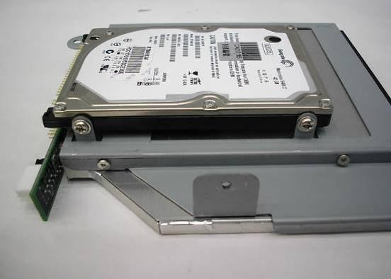
36 Replace the 3.5 HDD Remove the top cover as described in chapter 4.1. a. Disconnect the cables (2). b. Remove the screws (2) Replace the PCI Riser Card (1 x Slot) Remove the top cover as described in chapter 4.1. a. Remove the screw (1). b. Remove the PCI card towards you. 36


 that secures on the")
37 c. Remove the screws (2). d. Remove the PCI slot PCI Card Installation Remove the top cover as described in chapter 4.1. a. Remove the screw (1) that secures on the bracket. Then, remove the bracket. b. Insert the PCI card into the slot. 37
38 c. Tighten the screw (1). 38
39 5. Specification Model Name CPU Supports IT-6066 Intel ULV Celeron M 800MHz/1.0GHz (fanless); up to Celeron M 1.3/1.5GHz, Pentium M 1.8GHz Chipset System Memory Graphic Memory BIOS Storage HDD ODD Solid State Disk Expansion PCI Slot External I / O Ports Front I / O 852GM + ICH4 1 x DDR SO-DIMM slot, up to 1GB Share system memory 8 ~ 64MB AWARD BIOS 2.5" Slim HDD 3.5 HDD (Optional) Slim CD-ROM N/A Support Compact Flash Card by optional CF adapter card. 1-slot PCI riser card USB 2 Audio Line in 1 Line out 1 Rear I / O PS/2 Keyboard 1, Optional Y-cable for Mouse USB 2 Serial/COM 1 x RS-232 port, 1 x RS-232 / 422 / 485 port 2 x RS232 ports by COM3 / COM4 cable kits Parallel 1 LAN (10 / 100) 1 VGA 1 Rear I / O 2nd VGA Optional by DVI/ TV-out card 39
40 TV-Out Optional by DVI/ TV-out card DC Jack 1 Control Indicator Power Button 1 Indicator LED Power Power Adapter Option Power LED, HDD LED Default 65W DC-19V Power Adapter; Optional DC-19V 90W Power Adapter. Wall Mount Kit 2 Environment EMC & Safety Operating Temperature Storage Temperature Operating Humidity Storage Humidity Dimension (W x D x H mm/inch) CE, FCC Class A, LVD 0 ~35 C -20 ~ 60 C 5% to 95% RH, Non-condensing 5% to 95% RH, Non-condensing 243 x 218 x 50 mm 9.6 x 8.6 x 2.0 Weight (kg/lbs) N.W. Weight (kg/lbs) G.W. OS Support 2.3kg / 5.0lbs 2.8kg / 6.1lbs Microsoft Windows XP Professional, Windows XP Embedded - This specification is subject to change without prior notice. 40
41 6. Connectors and Jumper Settings 1. IT-6066 Motherboard 41
42 2. Connectors Connector Function Connector Function CN1 Power Connector For COM2 COM2 3.5" HDD CN3 Inverter Connector DIMM1 SO-DIMM DDR Memory CN4 DVO Connector F4 CPU Fan Connector CN5 LVDS Interface F7 System Fan Connector CN6 PCI SLOT IDE1 3.5 IDE Device CN7 Hardware Reset IDE2 Slim HD or CD-Rom CN8 IrDA Connector PRN1 Parallel Port CN9 COM3 PS1 Keyboard & Mouse CN10 COM4 PWR1 19V Power Adaptor CN11 CD-IN Connector RJ45_1 LAN Connector CN12 Speaker & MIC Connector USB1 USB Port 1 USB Port 2 CN14 Power Switch USB2 USB Port 5 USB Port 6 CN15 Audio Line-In USB3 USB Port 3 CN16 Audio Line-Out USB4 USB Port 4 COM1 COM1 VGA1 VGA Port 42
43 3. Jumper Settings 1. CMOS Operation Mode Factory Default Setting Function JP3 CMOS Normal N/C CMOS Reset Power Mode Setting Function ATX Power JP5 N/C AT Power COM2 RS232 / 485 / 422 Setting Function RS232 RS485 RS422 JP2 (1-2) JP2 (3-4) JP2 (4-6) JP2 (5-7) JP2 (7-8) JP2 (9-10) JP1(1-2) JP1(3-4) JP1(5-6) JP1(7-8) JP1(9-10) JP1(11-12) Short Short Short Short Short Short Short Short Short Short Short Short 43

44 4. LCD ID Setting Panel Resolution LVDS JP6 Number Bits Channel x Single SHORT SHORT SHORT SHORT x Single SHORT SHORT SHORT OPEN x Single SHORT SHORT OPEN SHORT x Dual SHORT SHORT OPEN OPEN x Single SHORT OPEN SHORT SHORT x Single SHORT OPEN SHORT OPEN 4. PCI Card Jumper Settings JP21 JP22 JP23 JP24 JP 21 REQ#5 / GNT#5 JP 22 SERIRQ / GPIO 21 Factory Default Setting 1-3, 2-4 Factory Default Setting 1-3, 2-4 JP 23 LPC JP 24 LPC Factory Default Setting 1, 3, 5 Factory Default Setting 1, 3, 5 44
45 7. Connector Pin Definition CN1 : Power Connector For 3.5" HDD Pin 1 +12V Pin 2 GND Pin 3 GND Pin 4 +5V CN3 : Inverter Connector Pin 1 +12V Pin 2 +12V Pin 3 +12V Pin 4 Back-light Enable Pin 5 Brightness Control Pin 6 GND Pin 7 GND Pin 8 GND CN4 : DVO Connector Pin 1 DVOC 11 Pin 2 DVOC_HSYNC Pin 3 DVOC 10 Pin 4 DVOC_VSYNC Pin 5 DVOC 9 Pin 6 GND Pin 7 DVOC 8 Pin 8 DVO_DETECT Pin 9 DVOC 7 Pin 10 DVOC_BLANK# Pin 11 DVOC 6 Pin 12 DVOC_FLDSTL Pin 13 DVOC 5 Pin 14 GND Pin 15 DVOC 4 Pin 16 DVI_MDVIDATA Pin 17 DVOC 3 Pin 18 DVI_MDVICLK Pin 19 DVOC 2 Pin 20 GND Pin 21 DVOC 1 Pin 22 DVOC_CLK# Pin 23 DVOC 0 Pin 24 DVOC_CLK Pin 25 +5V Pin 26 GND Pin 27 +5V Pin V Pin 29 +5V Pin V 45
46 CN5 : LVDS Interface Pin 1 LVDS_B0+ Pin 2 LVDS_A3+ Pin 3 LVDS_B0- Pin 4 LVDS_A3- Pin 5 GND Pin 6 GND Pin 7 LVDS_B1+ Pin 8 LVDS_CLKA+ Pin 9 LVDS_B1- Pin 10 LVDS_CLKA- Pin 11 GND Pin 12 GND Pin 13 LVDS_B2+ Pin 14 LVDS_A2+ Pin 15 LVDS_B2- Pin 16 LVDS_A2- Pin 17 GND Pin 18 GND Pin 19 LVDS_B3+ Pin 20 LVDS_A1+ Pin 21 LVDS_B3- Pin 22 LVDS_A1- Pin 23 GND Pin 24 GND Pin 25 LVDS_CLKB+ Pin 26 LVDS_A0+ Pin 27 LVDS_CLKB- Pin 28 LVDS_A0- Pin 29 GND Pin 30 GND Pin 31 +5V_LCDVDD Pin V_LCDVDD Pin 33 +5V_LCDVDD Pin V_LCDVDD Pin 35 +5V_LCDVDD Pin V_LCDVDD Pin 37 +5V_LCDVDD Pin V_LCDVDD Pin 39 +5V_LCDVDD Pin V_LCDVDD CN8 : IrDA Connector Pin 1 +5V Pin 2 IrDA_RX Pin 3 IrDA_TX Pin 4 GND 46
47 CN9 : COM3 Pin 1 DCD# Pin 2 RX# Pin 3 TX# Pin 4 DTR# Pin 5 GND Pin 6 DSR# Pin 7 RTS# Pin 8 CTS# Pin 9 RI Pin 10 +5V CN10 : COM4 Pin 1 DCD# Pin 2 RX# Pin 3 TX# Pin 4 DTR# Pin 5 GND Pin 6 DSR# Pin 7 RTS# Pin 8 CTS# Pin 9 RI Pin 10 +5V CN11 : CD- IN Connector Pin 1 CDIN_L Pin 2 CDIN_REF Pin 3 CDIN_R Pin 4 CDIN_REF CN12 : Speaker & MIC Connector Pin 1 AMP_ORL Pin 2 GND Pin 3 GND Pin 4 AMP_ORR Pin 5 GND Pin 6 MIC1 USB2 : USB5 & USB6 Pin 1 +5V_USB4 Pin 2 USB20_P4- Pin 3 USB20_P4+ Pin 4 GND Pin 5 +5V_USB5 Pin 6 USB20_P5- Pin 7 USB20_P5+ Pin 8 GND 47
48 8. BIOS Setting 1. BIOS Setup Utility The BIOS setup defines how the system is configured. You need to run this program the first time you configure this product. You may need to run it again if you change the configuration. You need to connect a PC keyboard to the keyboard connector to run the BIOS setup utility. 2. Starting the BIOS Setup 1. Turn on or reboot this product. 2. Press the DEL key immediately after the product is turned on, or press the DEL key when the following message is displayed during POST (the Power on Self-Test). Press DEL to enter SETUP. 3. The main menu of the BIOS setup is displayed. 4. If the supervisor password is set, you must enter it here. 3. When a Problem Occurs If, after making and saving system changes with the Setup utility, you find that this product no longer boots, start the BIOS setup and execute the following. Load Optimized Defaults 4. BIOS Main Menu When the BIOS Main Menu is displayed, the following items can be selected. Use the arrow keys to select items and the Enter key to accept and enter the sub-menu. 48

49 Standard CMOS Features Use this menu for basic system configuration. Advanced BIOS Features Use this menu to set the Advanced Features available on the system. Advanced Chipset Features Use this menu to change the values in the chipset registers and optimize the system s performance. Integrated Peripherals Use this menu to specify your settings for integrated peripherals. Power Management setup Use this menu to specify your settings for power management. PnP/PCI Configurations This entry appears if your system supports Plug and Play and PCI Configuration. PC health status Displays CPU, System Temperature, Fan Speed, and System Voltages Value. Load Optimized Defaults Use this menu to load the BIOS default values, i.e., factory settings for optimal performance system operations. While Award has designed the custom BIOS to maximize performance, the factory has the option to change these defaults to meet their needs. 49
50 Set Supervisor Password Enables you to change, set, or disable the supervisor or user password. Set Password Change, set, or disable the password. It allows you to limit access to the system and to the setup, or just to the setup. Save & exit setup Save CMOS value changes to CMOS and exits setup. Exit without saving Ignores all CMOS value changes and exits setup. 50
51 Appendix A: PCI Card Dimension Maximum dimension of the PCI add-on card: Component Side: 124.5mm x 81mm x 13mm (W x D x H) (Picture 1) Picture 1: Component side 51
52 Maximum dimension of the PCI add-on card: Bottom Side: 124.5mm x 81mm x 3mm (W x D x H) (Picture 2) Picture 2: Bottom Side 52
53 Appendix B: Wall Mount Kit Dimensions Figure 1 shows the system and wall mount kit dimensions. Figure 1: System and Wall Mount Kit Dimensions (mm) 53

54 The typical distance between the wall and the bottom of the system is 7mm. Figure 3 shows the wall mount kit dimensions. Figure 2: Mounting Height (mm) Figure 3: Wall Mount Kit Dimensions (mm) 54
55 Appendix C: Watch Dog Timer Programming Guide 1. Register Description CRF5 Bit3: Select WDT Count Mode =0 second =1 minute Bit7: 4 reserved Bit2: 1 reserved CRF6 (Default 0x00) Watch Dog Timer Time-out value. Writing a non-zero value to this register causes the counter to load the value to Watch Dog Counter and starts counting down. If Bit 7 and Bit 6 are set, any Mouse Interrupt or Keyboard Interrupt event will also cause the reload of a previously loaded non-zero value to Watch Dog Counter and starts counting down. Reading this register returns the current value in the Watch Dog Counter instead of the Watch Dog Timer Time-out value. Bit 7 0 = 0x00 Time-out Disable = 0x01 Time-out occurs after 1 second/minute = 0x02 Time-out occurs after 2 seconds/minutes = 0x03 Time-out occurs after 3 seconds/minutes... = 0xFF Time-out occurs after 255 seconds/minutes CRF7 (Default 0x00) Bit 7 : Mouse interrupt reset Enable or Disable = 1 Watch Dog Timer is reset upon a Mouse interrupt = 0 Watch Dog Timer is not affected by Mouse interrupt Bit 6 : Keyboard interrupt reset Enable or Disable = 1 Watch Dog Timer is reset upon a Keyboard interrupt = 0 Watch Dog Timer is not affected by Keyboard interrupt Bit5:0 reserved 55
56 2. Basic Process to Enter/Exit Watch Dog Timer Configuration Mode 2.1. Enter Watch Dog Timer Configuration Mode ; Write 87h to the location 4E twice. mov dx, 4Eh mov al, 087h out dx,al nop nop out dx,al ; Set Logical Device 8 mov dx,4eh mov al, 07h ;;Logical Device selector out dx,al mov dx,4fh mov al,08h ;;logical device 8 out dx,al 2.2. Exit Watch Dog Timer Configuration Mode mov dx, 4Eh mov al, 0AAh out dx,al 3. Register Setting Example Please follow the example procedure: Step 2.1 Step 3.1 Step 3.2 Step 3.5 Step Set Watch Dog Timer Counter Mode by Second mov dx, 4Eh mov al, 0F5h ;select CRF5 out dx,al mov dx,4fh in al,dx ;get original value and al,0f4h ;bit3=0, WDT count mode = second. ;Note: Must keep other bits value. out dx,al 3.2. Set Watch Dog Timer Counter Mode by Minute mov dx, 4Eh mov al, 0F5h ;select CRF5 out dx,al mov dx,4fh in al,dx ;get original value or al,08h ;bit3=1, WDT count mode = minute. ;Note: Must keep other bits value. out dx,al 56
57 3.3. PS/2 Mouse Interrupt Reset Watch Dog Timer mov dx, 4Eh mov al, 0F7h ;select CRF7 out dx, al mov dx,4fh in al,dx or al,80h ;Watch Dog Timer reset by mouse interrupt out dx,al 3.4. PS/2 Keyboard Interrupt Reset Watch Dog Timer mov dx, 4Eh mov al, 0F7h ;select CRF7 out dx, al mov dx,4fh in al,dx or al,40h ;Watch Dog Timer reset by keyboard interrupt out dx,al 3.5. Set Watch Dog Timer Counter Value mov dx, 4Eh mov al, 0F6h ;select CRF6 out dx, al mov dx,4fh mov al,xxh ;;set Time-out value here, xx=1~0ffh for Set Watch Dog Timer counter value out dx,al 3.6. Update Watch Dog Timer Counter Value Repeat step 3.3 to reset the Watch Dog Timer counter value to update the counter value Disable Watch Dog Timer Repeat step 3.3 to reset the Watch Dog Timer counter value to update the counter value. mov dx, 4Eh mov al, 0F6h ;select CRF6 out dx, al mov dx,4fh mov al, 00h ; set 0 to disable Watch Dog function. out dx,al Notice: A demo tool is provided on the Driver Bank CD. 57
EVO-TP Hardware System
 User Manual Revision v1.3 February 2010 EVO-TP Hardware System Copyright 2009 February All Rights Reserved Manual Version 1.1 Part Number: The information contained in this document is subject to change
EVO-TM2A EVO-TM2B Touch Screen Monitor
 User Manual Revision v1.3 Dec. 2010 EVO-TM2A EVO-TM2B Touch Screen Monitor Copyright 2010 August All Rights Reserved Manual Version 1.3 Part Number: The information contained in this document is subject
User Manual. TEOS Hardware System. November 2011 Revision 1.2 TEOS 1218/1216D TEOS 1518/1516D TEOS 1718/1716D TEOS 1918/1916D
 User Manual November 2011 Revision 1.2 TEOS Hardware System TEOS 1218/1216D TEOS 1518/1516D TEOS 1718/1716D TEOS 1918/1916D Copyright 2007~2011. All Rights Reserved Manual Version 1.2 The information contained
CP200 User Manual Point-of-Sale Hardware System
 CP200 User Manual Point-of-Sale Hardware System 2006 Dec V1.0 Copyright 2006 Dec All Rights Reserved Manual Version 1.0 The information contained in this document is subject to change without notice. We
POS 66X Series User Manual Point-of-Sale Hardware System
 POS 66X Series User Manual Point-of-Sale Hardware System P/N: 48201132 2006 June V1.1 Copyright 2006 June All Rights Reserved Manual Version 1.1 The information contained in this document is subject to
KPC Series. User Manual. i-tech Company LLC TOLL FREE: (888) WEB:
 WEB:") KPC Series User Manual i-tech Company LLC TOLL FREE: (888) 483-2418 EMAIL: info@i-techcompany.com WEB: www.i-techcompany.com Safety IMPORTANT SAFETY INSTRUCTIONS 1. To disconnect the machine from the electrial
KPC Series User Manual i-tech Company LLC TOLL FREE: (888) 483-2418 EMAIL: info@i-techcompany.com WEB: www.i-techcompany.com Safety IMPORTANT SAFETY INSTRUCTIONS 1. To disconnect the machine from the electrial
User Manual Version V1.1 March Elios Point-of-Sale Hardware System
 User Manual Version V1.1 March 2010 Elios Point-of-Sale Hardware System Copyright 2009~2010 All Rights Reserved Manual Version 1.1 The information contained in this document is subject to change without
POS 360 Series User Manual Point-of-Sale Hardware System
 POS 360 Series User Manual Point-of-Sale Hardware System 2007 January V1.0 Copyright 2007 January All Rights Reserved Manual Version 1.0 The information contained in this document is subject to change
Version 1.0 March 2014 OLC 10.1
 User Manual Version 1.0 March 2014 OLC 10.1 Copyright 2014 All Rights Reserved Manual Version 1.0 The information contained in this document is subject to change without notice. We make no warranty of
USER MANUAL. VERSION V1.0 March Saturn Plus
 USER MANUAL VERSION V1.0 March 2011 Saturn Plus Copyright 2011 March All Rights Reserved Manual Version 1.0 Part Number: 3LMKKPC70210 ii The information contained in this document is subject to change
POS 46X Series. Manual
 POS 46X Series Manual Point-of-Sale Hardware System P/N: 48201120 June 2005 V1.0 Copyright 2005 06 All Rights Reserved Manual Version 1.0 The information contained in this document is subject to change
Revision v1.3 December 2009 CS-200. Point-of-Sale Hardware System
 User Manual Revision v1.3 December 2009 CS-200 Point-of-Sale Hardware System Copyright 2007 Oct. ~ All Rights Reserved Manual Version 1.3 Part Number: The information contained in this document is subject
User Manual. June 2008 Revision 1.2b. Point of - Sale
 User Manual June 2008 Revision 1.2b Point of - Sale Hardware System Copyright 2008 June All Rights Reserved Manual Version 1.2b P/N: 48201273 The information contained in this document is subject to change
USER MANUAL VERSION V1.0 AUG MiniPOS Hardware System
 USER MANUAL VERSION V1.0 AUG 2010 MiniPOS Hardware System Copyright 2010 August All Rights Reserved Manual Version 1.0 Part Number: 3LMPPA530110 The information contained in this document is subject to
Service Manual. Squirrel Workstation WS9LA Point-of- Sale Hardware System
 Service Manual Revision v1.1 Jun-2012 Squirrel Workstation WS9LA 90-820 Point-of- Sale Hardware System Manual Version 1.1 P/N: 90-820 Information in this document is subject to change without notice. No
USER MANUAL. VERSION 1.2 April Saturn AIO(8 and 12 )
") USER MANUAL VERSION. April 03 Saturn AIO(8 and ) Copyright 009 All Rights Reserved Manual Version.0 The information contained in this document is subject to change without notice. We make no warranty of
USER MANUAL VERSION. April 03 Saturn AIO(8 and ) Copyright 009 All Rights Reserved Manual Version.0 The information contained in this document is subject to change without notice. We make no warranty of
Point-of-Sale Hardware System
 USER MANUAL VERSION V. January 20 Point-of-Sale Hardware System Copyright 20 All Rights Reserved Manual Version. Part Number: 3LMPP3850 ii The information contained in this document is subject to change
TEOS Hardware System TEOS 8416 / TEOS 1016/ TEOS1216
 TEOS Hardware System TEOS 8416 / TEOS 1016/ TEOS1216 Revision v1.1 November 2011 Copyright 2009~2011 All Rights Reserved Manual Version 1.1 The information contained in this document is subject to change
POS500/505 with B75 M/B Installation Guide Point-of-Sale Hardware System
 POS500/505 with B75 M/B Installation Guide Point-of-Sale Hardware System 48200280 July 2003 V1.0 1. Accessory External Floppy Cable External IDE Cable Power Cord Y Cable(Keyboard & Mouse) Serial Cable
User Manual. January 2009 Revision 1.0
 User Manual January 2009 Revision 1.0 Copyright 2009 January All Rights Reserved Manual Version 1.0 Part Number: 3LMPP4750100 The information contained in this document is subject to change without notice.
Version 1.0 July Acrobat All-in-One
 User Manual Version 1.0 July 2014 Acrobat All-in-One Copyright 2014 All Rights Reserved Manual Version 1.0 The information contained in this document is subject to change without notice. We make no warranty
USER MANUAL VERSION 1.3 JANUARY Jupiter PC
 USER MANUAL VERSION.3 JANUARY 0 Jupiter PC Copyright 0 All Rights Reserved Manual Version.3 Part Number: The information contained in this document is subject to change without notice. We make no warranty
SB-9090 All-in-One System. SB-9090 All-in-One System
 SB-9090 All-in-One System SB-9090 All-in-One System 1 Contents Notice...3 Safety Information...3 Caution on Lithium Batteries...3 Legislation and Weee Symbol...4 Package Contents...4 System Assembly and
User Manual. Version 1.3 December Point-of-Sale Hardware System
 User Manual Version 1.3 December 2012 Point-of-Sale Hardware System Copyright 2012 All Rights Reserved Manual Version 1.3 Part Number: The information contained in this document is subject to change without
Fit POS Terminal User Manual
 Fit POS Terminal User Manual Version 1.0 August 2014 1975 Midway Lane, Suite O Bellingham, WA 98226 sales@pos-x.com 360.738.8433 www.pos-x.com POS-X Warranty Industry-leading Warranty Protection 3 year
AMS Series. Fanless System
 AMS100-807 Series Fanless System User s Manual Version 1.0 Table of Contents Chapter 1 Specifications... 3 Chapter 2 AMS100-807 Series Features... 4 Chapter 3 System Dimensions... 5 Chapter 4 Opening the
USER MANUAL. VERSION 1.0 November TeosWide 10D2E 10D2P TeosWide 1007E 1007P
 USER MANUAL VERSION.0 November 03 TeosWide DE DP TeosWide 0E 0P Copyright 03 All Rights Reserved Manual Version.0 The information contained in this document is subject to change without notice. We make
ACS-2630 Box PC User Manual
 ACS-2630 Box PC User Manual Release Date Revision June 2006 V0.1 2005 Aplex Technology, Inc. All Rights Reserved. Published in Taiwan Aplex Technology, Inc. 9F-5, No. 2, Jian Pa Road, Chung Ho City, Taipei
User Manual FPC Fanless Panel PC. FPC8759: 21.5 Fanless Touch Panel PC with Atom D GHz Processor
 FPC 8759 Fanless Panel PC User Manual FPC8759: 21.5 Fanless Touch Panel PC with Atom D2550 1.86GHz Processor 14628 Central Ave, Chino, CA 91710 tel:909.597.7588, fax:909.597.1939 Copyright 2013 Acnodes,
iops-18 User Manual 2013 Oct V1 IBASE Technology Inc.
 www.ibase.com.tw iops-18 User Manual 2013 Oct V1 IBASE Technology Inc. iops-18 User Manual 1 Copyright 2013 IBASE Technology Inc. All Rights Reserved. No part of this manual, including the products and
4100 POS System User Guide
 4100 POS System 4100 User Guide Thank you for selecting UTC RETAIL s innovative Model 4100 Point of Sale solution! This guide is designed to acquaint you with the features and functionality of the 4100
Version 1.0 April 2015 NINÔ II
 User Manual Version 1.0 April 2015 NINÔ II Copyright 2015 All Rights Reserved Manual Version 1.0 The information contained in this document is subject to change without notice. We make no warranty of any
EPC-APL. Quick Reference Guide. Intel Pentium /Celeron Processor Fanless Tiny System. Copyright Notice. 1 st Ed 12 September 2017
 Intel Pentium /Celeron Processor Fanless Tiny System Quick Reference Guide 1 st Ed 12 September 2017 Copyright Notice Copyright 2017 ALL RIGHTS RESERVED. Part No. E2017CAI0A0R FCC Statement THIS DEVICE
Manual AMS ibase
 Manual AMS100-807 ibase Our company network supports you worldwide with offices in Germany, Austria, Switzerland, Great Britain and the USA. For more information please contact: FORTEC Elektronik AG Hauptniederlassung
PCM-9588 Intel Celeron M EBX SBC with DVI/ TTL/ VGA/ LVDS/ LAN/ 6 COM/ 2 SATA/ 6 USB2.0/16-bit GPIO Startup Manual
 PCM-9588 Intel Celeron M EBX SBC with DVI/ TTL/ VGA/ LVDS/ LAN/ 6 COM/ 2 SATA/ 6 USB2.0/16-bit GPIO Startup Manual Packing List Before you begin installing your card, please make sure that the following
AIMB-210 (Intel Atom processor N GHz FSB 533 MHz Mini-ITX Motherboard with VGA, LVDS, TV-Out, 6 COM, Dual GbE, 8 USB, 2 SATA II) Startup Manual
 Startup Manual") AIMB-210 (Intel Atom processor N270 6 GHz FSB 533 MHz Mini-ITX Motherboard with VGA, LVDS, TV-Out, 6 COM, Dual GbE, 8 USB, 2 SATA II) Startup Manual Before you begin installing your card, please make sure
AIMB-210 (Intel Atom processor N270 6 GHz FSB 533 MHz Mini-ITX Motherboard with VGA, LVDS, TV-Out, 6 COM, Dual GbE, 8 USB, 2 SATA II) Startup Manual Before you begin installing your card, please make sure
BYARM-181-PC. User Manual
 www.ibase.com.tw BYARM-8-PC User Manual IBASE Technology Inc. BYARM-8-PC User Manual 2 Revision Release Date V0. 205/02/03 Copyright 203 IBASE Technology Inc. All Rights Reserved. 2 BYARM-8-PC User Manual
PCA-6781 ISA Celeron M Half-sized SBC with VGA/ LCD/LVDS/10/100 Ethernet/USB2.0 and SSD Startup Manual
 PCA-6781 ISA Celeron M Half-sized SBC with VGA/ LCD/LVDS/10/100 Ethernet/USB2.0 and SSD Startup Manual Packing List Specifications Before you begin installing your card, please make sure that the following
User Manual. Version 1.0 August Point-of-Sale Hardware System
 User Manual Version 1.0 August 2016 Point-of-Sale Hardware System Copyright 2016 All Rights Reserved Manual Version 1.0 The information contained in this document is subject to change without notice. We
MPC-FR Series Fanless Ruggedized Marine Computer
 N W MARINE PC E S MPC-FR Series Fanless Ruggedized Marine Computer User Manual www.marinepc.com MPC-FR Series FCC Statement THIS DEVICE COMPLIES WITH PART 15 FCC RULES. OPERATION IS SUBJECT TO THE FOLLOWING
Thank you for selecting UTC RETAIL s innovative Model 1170 Point of Sale solution!
 1170 POS SYSTEM 1170 USER GUIDE Thank you for selecting UTC RETAIL s innovative Model 1170 Point of Sale solution! This guide is designed to acquaint you with the features and functionality of the 1170
PCM-4381 Intel Pentium M EPIC SBC with VGA/2 LVDS/ 2 Ethernet/ 4 COM/ 2 SATA/6 USB 2.0/ 16 bit GPIO
 PCM-4381 Intel Pentium M EPIC SBC with VGA/2 LVDS/ 2 Ethernet/ 4 COM/ 2 SATA/6 USB 2.0/ 16 bit GPIO Before you begin installing your card, please make sure that the following items have been shipped: 1.
ZOTAC ZBOX User s Manual
 ZOTAC ZBOX User s Manual No part of this manual, including the products and software described in it, may be reproduced, transmitted, transcribed, stored in a retrieval system, or translated into any language
ITA-1711 Series Fanless Compact Embedded IPC with Intel Celeron Dual Core CPU Startup Manual
 ITA-1711 Series Fanless Compact Embedded IPC with Intel Celeron Dual Core CPU Startup Manual Packing List Specifications Before you begin installing your IPC, please make sure that the following items
CPU. Intel Atom N455 Processor LAN. 2 x Intel 82583V PCIe Gigabit Ethernet
 8 EmModule-7E Wide Range Temperature PC/0 CPU Module Quick Installation Guide Version.0 Form Factor PC/0 CPU Module CPU Intel Atom N Processor Chipset Intel ICH8M Video Analog RGB/ Single Channel 8-bit
4170 POS System Installation Guide
 4170 POS System 4170 Installation Guide Thank you for selecting UTC RETAIL s innovative Model 4170 Point of Sale solution! This Installation Guide will help you efficiently install the 4170 POS. The document
Artisan Technology Group is your source for quality new and certified-used/pre-owned equipment
 Artisan Technology Group is your source for quality new and certified-used/pre-owned equipment FAST SHIPPING AND DELIVERY TENS OF THOUSANDS OF IN-STOCK ITEMS EQUIPMENT DEMOS HUNDREDS OF MANUFACTURERS SUPPORTED
User s Manual ITR-CS15D
 User s Manual ITR-CS15D Copyrights 2012 TALOS INTEGRATED TECHNOLGIES. All rights reserved. The information in this document is subject to change without prior notice in order to improve reliability, design
EVGA assumes you have purchased all necessary parts needed to allow for proper system functionality.
 Before You Begin Parts NOT in the Kit This kit contains all the hardware necessary to install and connect your new EVGA e-7050/610i GPU motherboard with integrated GeForce graphics processing. However,
User s Manual Full-Size PICMG 1.3 SHB Version 1.0
 3308360 User s Manual Full-Size PICMG 1.3 SHB Version 1.0 Copyrights This document is copyrighted and all rights are reserved. It does not allow any non authorization in copied, photocopied, translated
USER MANUAL BOX PC INEOS 800
 USER MANUAL BOX PC INEOS 800 User Manual Version 1.0 December 2012 Copyright Notice This document is copyrighted, 2012. All rights are reserved. The information contained in this document is subject to
TRADEMARK. Copyright 2011 All Rights Reserved Manual Version 1.1 Part Number: NPT-1500
 Copyright 2011 All Rights Reserved Manual Version 1.1 Part Number: NPT-1500 The information contained in this document is subject to changewithout notice. We make no warranty of any kind with regard to
NVR-CV. Network Video Recorder Hot-Swappable Tray for 3.5 HDD x 4 or 2.5 HDD x 4 Gigabit Ethernet x 2 COM x 2, USB2.0 x 6. VGA x 1, DVI-D x 1
 Netw ork Video Recorder N V R - CV Network Video Recorder Hot-Swappable Tray for 3.5 HDD x 4 or 2.5 HDD x 4 Gigabit Ethernet x 2 COM x 2, USB2.0 x 6 VGA x 1, DVI-D x 1 Manual 1st Ed. Oct. 2013 Copyright
SB1015W Widescreen All-in-one POS Terminal USER MANUAL
 SB1015W Widescreen All-in-one POS Terminal USER MANUAL Table of Contents 1 Introduction...2 1.1 Safety Information... 2 1.2 Electromagnetic compatibility statement... 3 2 Overview... 4 2.1 Features...
Rugged Panel PC AcuPanel 17 User Manual Revision 1.5
 ACURA EMBEDDED SYSTEMS INC. Rugged Panel PC AcuPanel 17 User Manual Revision 1.5 Contents Chapter 1: AcuPanel 17 Overview Specifications... 2 Knowing AcuPanel 17... 4 Rear Top... 4 Rear Bottom... 5 Rear
PPC-MB-8260AE (Intel Core i7/i5/i3/pentium/ Celeron LGA 1151 Mini-ITX with DP/VGA, 5 COM, 6 USB, Dual LAN, PCIe x4, Mini PCIe, DDR4) Startup Manual
 Startup Manual") PPC-MB-8260AE (Intel i7/i5/i3/pentium/ Celeron LGA 1151 Mini-ITX with DP/VGA, 5 COM, 6 USB, Dual LAN, PCIe x4, Mini PCIe, DDR4) Startup Manual Packing List Specifications Before card installation, ensure
PPC-MB-8260AE (Intel i7/i5/i3/pentium/ Celeron LGA 1151 Mini-ITX with DP/VGA, 5 COM, 6 USB, Dual LAN, PCIe x4, Mini PCIe, DDR4) Startup Manual Packing List Specifications Before card installation, ensure
LV-681. Mini-ITX motherboard. User s Manual. Edition: /04/09. LV-681 User s Manual 1
 LV-681 Mini-ITX motherboard User s Manual Edition: 1.00 2007/04/09 LV-681 User s Manual 1 Copyright The trademarks mentioned in the manual are legally registered to their respective companies. Disclaimer
PCM-9562 Intel Atom N450/D510 EBX SBC with 3LAN/6 COM/3 SATA/8 USB2.0/2 Watchdog Startup Manual
 PCM-9562 Intel Atom N450/D510 EBX SBC with 3LAN/6 COM/3 SATA/8 USB2.0/2 Watchdog Startup Manual Packing List Before you begin installing your card, please make sure that the following items have been shipped:
Network Camera. Quick Guide DC-B1203X. Powered by
 Network Camera Quick Guide DC-B1203X Powered by Safety Precautions English WARNING RISK OF ELECTRIC SHOCK DO NOT OPEN WARNING: TO REDUCE THE RISK OF ELECTRIC SHOCK, DO NOT REMOVE COVER (OR BACK). NO USER-SERVICEABLE
2190 POS System User Guide
 2190 POS System 2190 User Guide Thank you for selecting UTC RETAIL s innovative Model 2190 Point of Sale solution! This guide is designed to acquaint you with the features and functionality of the 2190
User s guide for Xtenda TM
 User s guide for Xtenda TM (X300 Series) Copyright by Ncomputing Co. Ltd. 2004. - Illegal copying of this software, hardware and this documentation is prohibited by law. All other brand- and product names
Pentium LGA775 High Performance 3D Gaming Motherboard
 AR-B1991 Pentium LGA775 High Performance 3D Gaming Motherboard Edition: 1.0 Book Number: AR-B1991-06.08.31 @Copyright 2005 All Rights Reserved. Manual first edition Apr 11, 2006 The information in this
LS8000 USER MANUAL. Kitchen Display Station Controller. with Android TM
 LS8000 Kitchen Display Station Controller with Android TM USER MANUAL NOTICE The manufacturer of the kitchen video controller makes no representations or warranties, either expressed or implied, by or
PCM-9386 Celeron M 3.5" SBC with MIO/VGA/LCD/LVDS Ethernet/USB2.0 and SSD
 PCM-9386 Celeron M 3.5" SBC with MIO/VGA/ LCD/LVDS Ethernet/USB2.0 and SSD Startup Manual Packing List Before you begin installing your card, please make sure that the following materials have been shipped:
Industrial PC IPC191V2. General Operating, Maintenance and Installation Manual. Hardware Platform Protocol Converter
 Industrial PC IPC191V2 General Operating, Maintenance and Installation Manual Hardware Platform Protocol Converter D-91056 Erlangen Phone: +49 9131 7677 47 Fax: +49 9131 7677 78 Internet: http://www.ipcomm.de
PowerBrick-CV User s Manual Edition 2.0
 The Power Brick-CV Users Manual PowerBrick-CV User s Manual Edition 2.0 Small footprint rugged Pentium-M With Digital Video Recorder The Power Brick-CV Users Manual Preface Copyright The material in this
PCM-9363 Intel Atom TM N455/D SBC, DDR3, 24-bit LVDS, CRT or HDMI, 2 Giga LANs, Mini PCIe, 3 COMs Startup Manual
 PCM-9363 Intel Atom TM N455/D525 3.5 SBC, DDR3, 24-bit LVDS, CRT or HDMI, 2 Giga LANs, Mini PCIe, 3 COMs Startup Manual Before you begin installing your card, please make sure that the following items
2100 POS System User Guide
 2100 POS System 2100 User Guide Thank you for selecting UTC RETAIL s innovative Model 2100 Point of Sale solution! This guide is designed to acquaint you with the features and functionality of the 2100
EmCORE-i65M3. Intel Celeron TM 827E Processor. 2 x Intel 82583V PCIe Gigabit Ethernet
 Form Factor 3.5" Compact Board EmCORE-i65M3 CPU Intel Celeron TM E Processor 3.5" Compact Board Quick Installation Guide Version. Chipset Intel PCH HM65 Video Dual Channels 4-bit LVDS/ DVI-I LAN x Intel
USER MANUAL. VERSION V1.2 July MiniPOS Hardware System
 USER MANUAL VERSION V1.2 July 2012 MiniPOS Hardware System Copyright 2012 All Rights Reserved Manual Version 1.2 Part Number: 3LMPP5620212 The information contained in this document is subject to change
MIL-STD Rugged Computer User's Manual. Version 1.0 Revision Date: July. 05, 2017 THOR200. MIL-STD Rugged Computer
 THOR200 MIL-STD Rugged Computer Safety information Electrical safety To prevent electrical shock hazard, disconnect the power cable from the electrical outlet before relocating the system. When adding
PCM-4153-A2 PC/104+ SBC w/amd LX800, VGA, LCD, Dual LAN, USB 2.0, On-board Flash and Memory Startup Manual
 PCM--A PC/0+ SBC w/amd LX800, VGA, LCD, Dual LAN, USB.0, On-board Flash and Memory Startup Manual Packing List Specifications Before you begin installing your card, please make sure that the following
FCC COMPLICANCE STATEMENT
 FCC COMPLICANCE STATEMENT For Users in the USA This equipment has been tested and found to comply with the limits for a Class B digital device, pursuant to Part 15 of FCC Rules. These rules are designed
AMI200 Series User Manual
 AMI200 Series User Manual 2012 August V4.0 Copyright 2010 IBASE Technology INC. All Rights Reserved. No part of this manual, including the products and software described in it, may be reproduced, transmitted,
CD-70 USB Display User Manual
 CD-70 USB Display User Manual CONTENTS CHAPTER 1 SAFETY...3 CHAPTER 2 INTRODUCTION...5 CHAPTER 3 INSTALLATION...7 CHAPTER 4 MOUNTING...10 CHAPTER 5 OPERATION...11 CHAPTER 6 TECHNICAL SUPPORT...16 2 PRECAUTIONS
Handbuch. DAVIDE Mini PC GRAFENTHAL
 Handbuch GRAFENTHAL DAVIDE Mini PC GRAFENTHAL GmbH von-monschaw-straße 3 47574 Goch info@grafenthal.de www.grafenthal.de Copyright 2017 GRAFENTHAL GmbH, Alle Rechte vorbehalten. GRAFENTHAL ist eine eingetragene
QK5P1000-Manual_Cover-135x135mm_PrintReady.eps 1 2/7/ :52:09 AM CMY 291-MB384-01S4F
 QK5P1000-Manual_Cover-135x135mm_PrintReady.eps 1 2/7/2018 11:52:09 AM C M Y CM MY CY CMY K 291-MB384-01S4F User s Manual No part of this manual, including the products and software described in it, may
1151 CPU, DP/ VGA, 5 COM, 6 USB,
 PPC-MB-8260AE Mini-ITX Motherboard with Intel Core i7/i5/i3/pentium /Celeron LGA 1151 CPU, DP/ VGA, 5 COM, 6 USB, Dual LAN, PCIe x4, and Mini PCIe Startup Manual Packing List Specifications Before card
Colorful Technology Website:
 Colorful Technology Website: http://www.colorful.cn Thanks for purchasing our based on Intel B250 Chipset motherboard. The motherboard C.B250A-BTC PLUS V20 based on Intel B250 Express Chipset, support
ZOTAC ZBOX. User s Manual
 User s Manual No part of this manual, including the products and software described in it, may be reproduced, transmitted, transcribed, stored in a retrieval system, or translated into any language in
8806 Series. 15 Multi-functional Touch Panel PC. Quick Reference Guide
 8806 Series 15 Multi-functional Touch Panel PC Quick Reference Guide 1st Ed 10 July, 2009 8806 Contents 1. Getting Started...3 1.1 Safety Precautions...3 1.2 Packing List...3 1.3 System Specifications...4
PCM-9584 Onboard Intel Pentium M EBX SBC with Audio, VGA 2LVDS and LAN
 PCM-9584 Onboard Intel Pentium M EBX SBC with Audio, VGA 2LVDS and LAN Packing List Before you begin installing your card, please make sure that the following materials have been shipped: 1 PCM-9584 all-in-one
ZOTAC ZBOX. User s Manual
 User s Manual ZOTAC ZBOX No part of this manual, including the products and software described in it, may be reproduced, transmitted, transcribed, stored in a retrieval system, or translated into any language
ZOTAC ZBOX. User s Manual
 User s Manual ZOTAC ZBOX No part of this manual, including the products and software described in it, may be reproduced, transmitted, transcribed, stored in a retrieval system, or translated into any language
G-MAX TM. ATX Series User s Manual
 Copyright Notice Copyright 2001 Gigabyte Technology. All Rights Reserved. No part of this documentation, including but not limited to the products and software described in it, may be reproduced, transmitted,
Network Application Platform. User s Manual
 525 Network Application Platform User s Manual Rev:1.0 Date:2012.03 CONTENTS CHAPTER 1 PACKAGE CONTENTS... 3 CHAPTER 2 INTRODUCTION... 4 CHAPTER 3 LAYOUT... 5 CHAPTER 4 REAR PANEL SKETCH MAP... 5 CHAPTER
CAF-1000 Series Communication Appliance. User s Manual Revision: 1.0
 CAF-1000 Series Communication Appliance User s Manual Revision: 1.0 CE This certificate of conformity of COS-0906 series with actual required safety standards in accordance with 89/366 ECC-EMC Directive
The ROBO-8710VLA package should cover the following basic items
 The ROBO-8710VLA all-in-one full size single board computer is designed to fit high performance and scalable Intel Pentium 4/Celeron processors and compatible for high-end industrial computer system with
MARINE PC MPC-PPC12. Marine Grade 12.1 LCD Monitor with 1.8 GHZ Dual Core Computer. MPC-PPC12 Manual December 2012
 N W MARINE PC E S MPC-PPC12 Marine Grade 12.1 LCD Monitor with 1.8 GHZ Dual Core Computer MPC-PPC12 Manual December 2012 Copyright Notice This document is copyrighted, 2012. All rights are reserved. The
1.1.Packing Contents 1*Colorful C.B250A-BTC V20 motherboard 2*SATA cables 1*Driver/Utility CD 1*User's Guide 1*I/O shield 1.2.MOTHERBOARD SPEC CPU
 Colorful Technology Website: http://www.colorful.cn Thanks for purchasing our based on Intel B250 Chipset motherboard. The motherboard C.B250A-BTC V20 based on Intel B250 Express Chipset, support Intel
ROBO-603. User's Manual
 ROBO-603 Embedded System Board User's Manual P/N: 861106030041 Version 1.0 Copyright Portwell, Inc., 2001. All rights reserved. All other brand names are registered trademarks of their respective owners.
291-MB333-04P7F EN1070K
 291-MB333-04P7F EN1070K User s Manual ZOTAC ZBOX No part of this manual, including the products and software described in it, may be reproduced, transmitted, transcribed, stored in a retrieval system,
PCM-9388 Celeron M 3.5 SBC with PC/104, VGA/ TTL/LVDS Ethernet/USB 2.0 and SSD Startup Manual
 PCM-9388 Celeron M 3.5 SBC with PC/104, VGA/ TTL/LVDS Ethernet/USB 2.0 and SSD Startup Manual Packing List Specifications Before installation, please make sure that you have received the following: 1.
Thank you for selecting UTC RETAIL s innovative Model 1170 Point of Sale solution!
 1170 POS SYSTEM 1170 INSTALLATION GUIDE Thank you for selecting UTC RETAIL s innovative Model 1170 Point of Sale solution! This Installation Guide will help you efficiently install the 1170 POS. The document
Keyboard PC User Manual
 Keyboard PC User Manual Version 1.0 Jun. 2010 1 DMP Electronics Inc. Copyright The information in this manual is subject to change without notice for continuous improvement in the product. All rights are
PCM-9361 Intel Atom N SBC with PC/104, VGA/ TTL/LVDS Ethernet/USB 2.0, SATA and SSD Startup Manual
 PCM-9361 Intel Atom N270 3.5 SBC with PC/104, VGA/ TTL/LVDS Ethernet/USB 2.0, SATA and SSD Startup Manual Packing List Specifications Before you begin installing your card, please make sure that the following
ZOTAC ZBOX User s Manual
 ZOTAC ZBOX User s Manual No part of this manual, including the products and software described in it, may be reproduced, transmitted, transcribed, stored in a retrieval system, or translated into any language
ZOTAC ZBOX User s Manual
 User s Manual No part of this manual, including the products and software described in it, may be reproduced, transmitted, transcribed, stored in a retrieval system, or translated into any language in
WG 10 /12 Series. Quick Reference Guide /12.1 Multifunctional Touch Panel PC. Copyright Notice
 10.4 /12.1 Multifunctional Touch Panel PC Quick Reference Guide Copyright Notice Copyright 2007-2009 Technology Inc., ALL RIGHTS RESERVED. Part No. E20171203A0R Contents 1. Getting Started...3 1.1 Safety
User Manual EBPC Embedded Industrial Computer Chassis for 3.5 Biscuit SBCs
 User Manual EBPC-3500 Embedded Industrial Computer Chassis for 3.5 Biscuit SBCs Copyright The documentation and the software included with this product are copyrighted 2008 by Advantech Co., Ltd. All rights