APPLICATION NOTES H-coupling
|
|
|
- Bryce Jackson
- 6 years ago
- Views:
Transcription


1 APPLICATION NOTES H-coupling Application description Functional description Wiring Basic setup Flowcharts Document no.: A SW version 3.3X.X or later
2 Table of contents 1. WARNINGS AND LEGAL INFORMATION... 3 LEGAL INFORMATION AND RESPONSIBILITY... 3 ELECTROSTATIC DISCHARGE AWARENESS... 3 SAFETY ISSUES... 3 DEFINITIONS APPLICATION SETUP... 4 DEFINITIONS APPLICATION DESCRIPTION... 5 SYSTEM OVERVIEW... 5 REQUIRED HARDWARE FUNCTIONAL DESCRIPTION... 7 DISPLAY WIRING AGC MAINS AGC DG BTB BASIC SETUP POWER PLANT CONFIGURATOR AOP-1 SETUP FLOWCHARTS FIXED POWER TO MAINS MAINS FAILURE (MAINS 17) DEIF A/S Page 2 of 19
3 1. Warnings and legal information This chapter includes important information about general legal issues relevant in the handling of DEIF products. Furthermore, some overall safety precautions will be introduced and recommended. Finally, the highlighted notes and warnings, which will be used throughout this handbook, are presented. Legal information and responsibility DEIF takes no responsibility for installation or operation of the generator set. If there is any doubt about how to install or operate the generator set controlled by the unit, the company responsible for the installation or the operation of the set must be contacted. The units are not to be opened by unauthorised personnel. If opened anyway, the warranty will be lost. Electrostatic discharge awareness Sufficient care must be taken to protect the terminals against static discharges during the installation. Once the unit is installed and connected, these precautions are no longer necessary. Safety issues Installing the unit implies work with dangerous currents and voltages. Therefore, the installation should only be carried out by authorised personnel who understand the risks involved in working with live electrical equipment. Be aware of the hazardous live currents and voltages. Do not touch any AC measurement inputs as this could lead to injury or death. Definitions Throughout this document a number of notes and warnings will be presented. To ensure that these are noticed, they will be highlighted in order to separate them from the general text. Notes The notes provide general information which will be helpful for the reader to bear in mind. Warnings The warnings indicate a potentially dangerous situation which could result in death, personal injury or damaged equipment, if certain guidelines are not followed. DEIF A/S Page 3 of 19
4 2. Application setup Setup of the power management application is done in the below listed menus and in the PC utility software. Even small changes in these menus can change the sequences a lot and will give you the possibility to customise the application to fulfil your needs. The functionality and influence of the application will be described briefly for each of the menus. The menus to take into consideration are: AGC mains Menu 8180 Menu 8020 Menu 8190 Menu 7080 AGC bus tie Menu 2300 AGC gen. Menu 8000 Menu 8010 Menu 8020 Function MB TB BTB GB AGC mains AGC bus tie AGC gen. Section Static section Dynamic section Common set point USW Definitions Description Mains Breaker. Tie Breaker. Bus Tie Breaker. Generator Breaker. Controlling an MB and a TB. Controlling a BTB. Controlling a gen-set and a GB. Part of the total application which is separated by one or two open BTBs. An application can contain up to 9 sections. Part of the total application which is separated by one or two open BTBs. There will be no closed BTBs within this section itself. Part of the total application which is separated by one or two open BTBs. There may be one or more closed BTBs within this section A set point which has to be identical for all AGC units to ensure correct functionality. A common set point is broadcasted on the CAN communication between the AGC units and will be changed back to the original set point. Utility software. The PC tool used to configure the AGC controllers. Pleas refer to the option G5 manual for detailed descriptions. DEIF A/S Page 4 of 19
5 3. Application description System overview This document describes what is needed to make a control system to an emergency power plant consisting of two mains connections, 4 diesel generators and one bus coupler connected like shown on the single line diagram below. The drawing shows 4 generators, but the system supports up to 16 generators. The system will be made with the following functionalities: 1. Section 1 will be operating in automatic mains failure (AMF) mode. 2. Section 2 will be in fixed power mode with automatic shift to automatic mains failure (AMF) in case of a mains failure. 3. Test mode will be a full test on each mains individually. 4. Additional display units (DU-2) with an AOP-1 for each mains unit. DEIF A/S Page 5 of 19
6 Required hardware To support this application, the following hardware is required: Mains breaker and tie breaker control 2 AGC mains units with standard display and the following options: Option G5 (power management) Option J1 (display cable) Option X2 (additional display unit) Option X3 (AOP-1) Regarding mains protection, please refer to the requirements from the local utility company. Gen-set control 4 AGC units with standard display and the following options: Option D1 (AVR control) Option G4 or G5 (power management) Option J1 (display cable) Additional options regarding generator protection should be added, if needed. The required interface for the governor and AVR should be taken into consideration. Please refer to the document Interfacing DEIF equipment to governors and AVRs. Bus coupler control 1 AGC bus tie unit with the following options: Option G4 or G5 (power management) Option X2 (display) Option J1 (display cable) The AGC bus tie unit can be replaced by a uni-line relay type FAS-113DG. Please refer to the data sheet for specific information about the possible options selection and order specification. DEIF A/S Page 6 of 19
7 4. Functional description In normal conditions, the application will work as 2 separate sections and the mains supervision will be done on each mains independently of the other. In case of a mains failure on one of the mains connections the gen-sets in each system will supply the load. However, in case of low available power the system will be allowed to close the BTB and use the gen-sets in the other system as well. Fixed power to mains When the plant is started, the gen-sets will be started, synchronise to prioritised mains, ramp up and produce power according to the fixed power set point. Test mode When activated, the test mode will be a full test on each mains individually. Start and stop engines The AGC will control the start and stop of the engine. This is done automatically or controlled by the operator in Semi-auto or Manual. Synchronisation of breakers Synchronisation of the breakers is done automatically according to the plant mode, or it can be done in Semi-auto by the operator. Mains failure sequence Normal condition (DGs are not running): - Mains supply OK - MB17 and MB18 closed - TB17 and TB18 open - BTB33 open - All gen-sets stopped Mains failure on mains 17 (auto switch adjusted to static section menu 8184): - MB17 is tripped - DG1 and DG2 are started, the first to be ready will close its GB on the black busbar, and the other GB will be synchronised - TB17 will be closed Load increases above the limit of 2 gen-sets: - BTB33 is closed - DG3 is started and synchronised - If needed, DG4 is started and synchronised Mains restored on mains 17: - MB17 is synchronised and closed (mains parallel = ON menu 8182) - TB17 is opened - All GBs and BTB33 are opened - Gen-sets will cool down and stop DEIF A/S Page 7 of 19
8 Fixed power to mains - Start is activated - The needed gen-sets are started and synchronised to mains - If more than 2 gen-sets are needed, BTB33 is closed and additional gen-sets are started and synchronised (depends on settings) - The gen-sets ramp up to the fixed power set point Display The display of the AGC used in this application looks like this: Generator unit BTB unit DEIF A/S Page 8 of 19
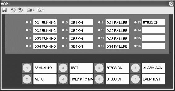
9 Mains unit AOP-1 DEIF A/S Page 9 of 19
10 5. Wiring The purpose of this chapter is to show the signals that are required as a minimum to run this application. The required signals are marked with an arrow. AGC mains DEIF A/S Page 10 of 19
11 For guidelines regarding wiring, please refer to the Installation Instructions. DEIF A/S Page 11 of 19
12 AGC DG DEIF A/S Page 12 of 19
13 For guidelines regarding wiring, please refer to the Installation Instructions. DEIF A/S Page 13 of 19
14 BTB DEIF A/S Page 14 of 19
15 DEIF A/S Page 15 of 19


16 6. Basic setup Power plant configurator DEIF A/S Page 16 of 19


17 AOP-1 setup DEIF A/S Page 17 of 19
18 7. Flowcharts Fixed power to mains 18 DEIF A/S Page 18 of 19
19 Mains failure (mains 17) DEIF A/S reserves the right to change any of the above DEIF A/S Page 19 of 19
AGC 200 Advanced Gen-set Controller What s in the delivery? Getting started The first steps Using the AGC 200
 QUICK START GUIDE AGC 200 Advanced Gen-set Controller What s in the delivery? Getting started The first steps Using the AGC 200 DEIF A/S Frisenborgvej 33 DK-7800 Skive Tel.: +45 9614 9614 Fax: +45 9614
Automatic Genset Controller, AGC-4 What s in the delivery? Getting started The first steps Using the AGC
 QUICK START GUIDE Automatic Genset Controller, AGC-4 What s in the delivery? Getting started The first steps Using the AGC DEIF A/S Frisenborgvej 33 DK-7800 Skive Tel.: +45 9614 9614 Fax: +45 9614 9615
Automatic Genset Controller, AGC-3 What's in the delivery Getting started The first steps Using the AGC
 QUICK START GUIDE Automatic Genset Controller, AGC-3 What's in the delivery Getting started The first steps Using the AGC DEIF A/S Frisenborgvej 33 DK-7800 Skive Tel.: +45 9614 9614 Fax: +45 9614 9615
Automatic Genset Controller, AGC-4 What s in the delivery? Getting started The first steps Using the AGC
 QUICK START GUIDE Automatic Genset Controller, AGC-4 What s in the delivery? Getting started The first steps Using the AGC DEIF A/S Frisenborgvej 33 DK-7800 Skive Tel.: +45 9614 9614 Fax: +45 9614 9615
QUICK START GUIDE Generator Paralleling Controller, GPC-3 Generator Protection Unit, GPU-3/GPU-3 Hydro Paralleling and Protection Unit, PPU-3
 QUICK START GUIDE Generator Paralleling Controller, GPC-3 Generator Protection Unit, GPU-3/GPU-3 Hydro Paralleling and Protection Unit, PPU-3 What's in the delivery? Getting started The first steps PC
DEIF A/S. Description of options. Option P1, Event and alarm printer Automatic Gen-set Controller. Description of option. Functional description
 Description of options Option P1, Event and alarm printer Automatic Gen-set Controller 4189340377B SW version 2.1X.X Description of option DEIF A/S Functional description Parameter list DEIF A/S, Frisenborgvej
APPLICATION NOTES Translations
 APPLICATION NOTES Translations Reading, editing and writing of translations from within USW 3 Document no.: 4189340630D This document covers the following products: AGC 200 from SW version 3.5x.x or later
Option X4 Additional Operator Panel AOP-2 Description of option Functional description
 MULTI-LINE 2 DESCRIPTION OF OPTIONS Option X4 Additional Operator Panel AOP-2 Description of option Functional description DEIF A/S Frisenborgvej 33 DK-7800 Skive Tel.: +45 9614 9614 Fax: +45 9614 9615
Option P1 Event and alarm printer Description of option Functional description Parameter list
 MULTI-LINE 2 DESCRIPTION OF OPTIONS Option P1 Event and alarm printer Description of option Parameter list DEIF A/S Frisenborgvej 33 DK-7800 Skive Tel.: +45 9614 9614 Fax: +45 9614 9615 info@deif.com www.deif.com
DEIF A/S. Description of options. Option C2, Generator add-on protection package Automatic Gen-set Controller. Description of option
 Description of options Option C2, Generator add-on protection package Automatic Gen-set Controller 4189340345C SW version 2.1X.X Description of option Functional description DEIF A/S Parameter list DEIF
DEIF A/S. Description of options. Option C1 Generator add-on protection package Multi-line 2 version 2. Description of options. Functional description
 Description of options Option C1 Generator add-on protection package Multi-line 2 version 2 4189340267E SW version 2.42.X Description of options DEIF A/S Functional description Parameter list DEIF A/S,
DEIF A/S. Description of options. Option A and B, Loss of mains protection package Automatic Gen-set controller. Description of options
 Description of options Option A and B, Loss of mains protection package Automatic Gen-set controller 4189340394B SW 2.3X.X Description of options Functional descriptions DEIF A/S Parameter list DEIF A/S,
Compact Genset Controller, CGC 400 What's in the delivery? The first steps Push-buttons and LEDs
 QUICK START GUIDE Compact Genset Controller, CGC 400 What's in the delivery? The first steps Push-buttons and LEDs DEIF A/S Frisenborgvej 33 DK-7800 Skive Tel.: +45 9614 9614 Fax: +45 9614 9615 info@deif.com
OPERATOR'S MANUAL Generator Paralleling Controller, GPC-3 - Generator Protection Unit, GPU-3/GPU-3 Hydro - Paralleling and Protection Unit, PPU-3
 OPERATOR'S MANUAL Generator Paralleling Controller, GPC-3 - Generator Protection Unit, GPU-3/GPU-3 Hydro - Paralleling and Protection Unit, PPU-3 Display and push-button functions Alarm handling Log list
MULTI-LINE 2 APPLICATION NOTES
 MULTI-LINE 2 APPLICATION NOTES Converting PPM-2 to PPM 300 Parameter conversion Wiring Options I/O list Modbus DEIF A/S Frisenborgvej 33 DK-7800 Skive Tel.: +45 9614 9614 Fax: +45 9614 9615 info@deif.com
Option H10, Multi-line 2 unit with USB service port. To be used when the multi-line 2 unit service port is USB type
 Description of options Option H10, Multi-line 2 unit with USB service port 4189340418A To be used when the multi-line 2 unit service port is USB type DEIF A/S Hardware option DEIF A/S, Frisenborgvej 33
Option H3 Serial communication Profibus DP
 MULTI-LINE 2 DESCRIPTION OF OPTIONS Option H3 Serial communication Profibus DP Description of option Functional description Parameters Data tables Document no.: 4189340443H Multi-line 2 Option H3, Serial
Inverter Interface Interface examples Wiring examples Communication topology
 ASC APPLICATION NOTES Inverter Interface Interface examples Wiring examples Communication topology DEIF A/S Frisenborgvej 33 DK-7800 Skive Tel.: +45 9614 9614 Fax: +45 9614 9615 info@deif.com www.deif.com
Getting started - USW 3.x Software download from internet Software installation Device setup Data backup
 MULTI-LINE 2 APPLICATION NOTES Getting started - USW 3.x Software download from internet Software installation Device setup Data backup DEIF A/S Frisenborgvej 33 DK-7800 Skive Tel.: +45 9614 9614 Fax:
MULTI-LINE 2 APPLICATION NOTES. Converting PPU-2 to PPU-3 Parameter conversion Wiring Options I/O list. Document no.: A SW version:
 MULTI-LINE 2 APPLICATION NOTES Converting PPU-2 to PPU-3 Parameter conversion Wiring Options I/O list DEIF A/S Frisenborgvej 33 DK-7800 Skive Tel.: +45 9614 9614 Fax: +45 9614 9615 info@deif.com www.deif.com
Genset control and protection with safety system
 APPLICATION NOTES Generator Protection Unit, GPU-3 APPLICATION NOTES Genset control and protection with safety system Application description Functional description Wiring I/O lists Basic setup Flowcharts
Advanced Graphical Interface, AGI 100
 APPLICATION NOTES Advanced Graphical Interface, AGI 100 The AGI communication ports Modbus details Specific DEIF driver Example of project creation Document no.: 4189340746A DEIF Screen Designer 1.293
MULTI-LINE 2 DESCRIPTION OF OPTIONS
 MULTI-LINE 2 DESCRIPTION OF OPTIONS Option N Modbus TCP/IP Document no.: 4189340612D This description of options covers the following products: AGC 200 series APU 200 series Utility Software SW version
Option M2 Configurable engine control cards Multi-line 2 version B SW version 2.4X.X
 Description of options Option M2 Configurable engine control cards Multi-line 2 version 2 4189340482B SW version 2.4X.X Description of options Functional description DEIF A/S Display units Additional functions
Option H8.x and H12.x External I/O modules Description of option Functional description
 MULTI-LINE DESCRIPTION OF OPTIONS Option H8.x and H12.x External I/O modules Description of option Functional description DEIF A/S Frisenborgvej 33 DK-7800 Skive Tel.: +45 9614 9614 Fax: +45 9614 9615
DEIF A/S. Description of options. Option H4 Serial comm. CAT CCM communication Multi-line 2 version 2. Description of option Functional description
 of options Option H4 Serial comm. CAT CCM communication Multi-line 2 version 2 4189340280F SW version 2.4X.X of option Functional description DEIF A/S Parameter list CCM lists Customised lists Single parameter
APPLICATION NOTES DELOMATIC 4, DM-4 GAS/HYDRO
 APPLICATION NOTES DELOMATIC 4, DM-4 GAS/HYDRO Remote Monitoring TCP/IP DSL DSL TCP/IP DSL Mobile TCP/IP Mobile DSL TCP/IP Mobile Mobile Document no.: 4189340650A Table of contents 1. ABOUT THIS DOCUMENT...
QUICK START GUIDE Paralleling and Protection Unit PPU 300
 QUICK START GUIDE Paralleling and Protection Unit PPU 300 DEIF A/S Frisenborgvej 33 DK-7800 Skive Tel.: +45 9614 9614 Fax: +45 9614 9615 info@deif.com www.deif.com Document no.: 4189341107B 1. Introduction
CODESYS v. 2.3, Ethernet driver for AGI 3xx Use the CODESYS Ethernet driver in the AGI Creator Set up the CODESYS for use with the AGI Creator
 APPLICATION NOTES CODESYS v. 2.3, Ethernet driver for AGI 3xx Use the CODESYS Ethernet driver in the AGI Creator Set up the CODESYS for use with the AGI Creator DEIF A/S Frisenborgvej 33 DK-7800 Skive
QUICK START GUIDE Paralleling and Protection Unit PPU 300
 QUICK START GUIDE Paralleling and Protection Unit PPU 300 DEIF A/S Frisenborgvej 33 DK-7800 Skive Tel.: +45 9614 9614 Fax: +45 9614 9615 info@deif.com www.deif.com Document no.: 4189341107C 1. Introduction
QUICK START GUIDE Generator Protection Unit GPU 300
 QUICK START GUIDE Generator Protection Unit GPU 300 DEIF A/S Frisenborgvej 33 DK-7800 Skive Tel.: +45 9614 9614 Fax: +45 9614 9615 Info@deif.com www.deif.com Document no.: 4189341035A 1. Introduction 1.1
MULTI-LINE 2 APPLICATION NOTES. Converting PPM-2 to PPM-3 Parameter conversion Wiring Options I/O list Modbus. Document no.: A SW version:
 MULTI-LINE 2 APPLICATION NOTES Converting to Parameter conversion Wiring Options I/O list Modbus DEIF A/S Frisenborgvej 33 DK-7800 Skive Tel.: +45 9614 9614 Fax: +45 9614 9615 info@deif.com www.deif.com
General introduction Part 2, chapter 11
 Delomatic 4 DM-4 Land/DM-4 Marine General introduction Part 2, chapter 11 DEIF A/S Page 1 of 8 Document no.: 4189232111C Table of contents 11. THE DELOMATIC SYSTEM IN GENERAL... 3 GENERAL INTRODUCTION...
EAP 300 REMOTE ANNUNCIATOR INSTALLATION MANUAL. r.0454a
 EAP 300 REMOTE ANNUNCIATOR INSTALLATION MANUAL r.0454a PM084 Rev 0 08/06/20 9087A 198 th Street, Langley, BC Canada V1M 3B1 Telephone (604) 888-0110 Telefax (604) 888-3381 E-Mail: info@thomsontechnology.com
Multi-instrument Communication, MIC-2 MKII DIN Quick Start Guide
 Multi-instrument Communication, MIC-2 MKII DIN Quick Start Guide Warnings and legal information Installation and terminals Communication I/O options Alarming Utility software More information Specifications
Installation Manual. Multi Power Controller MPC-1 multi-line D
 Installation Manual Multi Power Controller MPC-1 multi-line Complete control system in one package: - island operation - parallel with mains operation - emergency generator control 3-phase AC measurements
Multi-instrument Communication, MIC-2 MKII DIN Quick Start Guide
 Multi-instrument Communication, MIC-2 MKII DIN Quick Start Guide Warnings and legal information Installation and terminals Communication I/O options Alarming Utility software More information Specifications
Compact Genset Controller, CGC 200 Mounting Terminals and wiring Commissioning, using the Utility Software and/or the front panel
 INSTALLATION AND COMMISSIONING INSTRUCTIONS Compact Genset Controller, CGC 200 Mounting Terminals and wiring, using the Utility Software and/or the front panel DEIF A/S Frisenborgvej 33 DK-7800 Skive Tel.:
M-Logic Internal Logic Controller Description of M-Logic Functional description List of possible selections for logics
 MULTI-LINE 2 APPLICATION NOTES M-Logic Internal Logic Controller Description of M-Logic Functional description List of possible selections for logics DEIF A/S Frisenborgvej 33 DK-7800 Skive Tel.: +45 9614
INSTALLATION INSTRUCTIONS
 INSTALLATION INSTRUCTIONS AGC 200 Advanced Gen-set Controller Mounting Terminal strip overview I/O lists Wiring Document no.: 4189340610C SW version 3.5X.X or later Table of contents 1. ABOUT THIS DOCUMENT...
Genset Controller Unit Model EMS - GC10. Installation Manual Section
 Genset Controller Unit Model EMS - GC10 Installation Manual 00-02-0794 Section 75 2013-01-28 In order to consistently bring you the highest quality, full featured products, we reserve the right to change
Input Power Selector Switch. Product Manual (Revision NEW) Original Instructions for use with Generator Set Control Assembly
 Original Instructions for use with Generator Set Control Assembly") Product Manual 82017 (Revision NEW) Original Instructions 9900-471 for use with 8272-713 Generator Set Control Assembly Operation Manual General Precautions Read this entire manual and all other publications
Product Manual 82017 (Revision NEW) Original Instructions 9900-471 for use with 8272-713 Generator Set Control Assembly Operation Manual General Precautions Read this entire manual and all other publications
APPLICATION NOTES. Advanced Graphical Interface - AGI Internal PLC (CODESYS V3) SHENDONG
 SHENDONG") APPLICATION NOTES Advanced Graphical Interface - AGI Internal PLC (CODESYS V3) SHENDONG CODESYS V3 logic running on AGI 300/400 series product Support of Modbus/TCP and RTU communication Use of remote
APPLICATION NOTES Advanced Graphical Interface - AGI Internal PLC (CODESYS V3) SHENDONG CODESYS V3 logic running on AGI 300/400 series product Support of Modbus/TCP and RTU communication Use of remote
Delomatic 4, DM-4 Land DATA SHEET
 Delomatic 4, DATA SHEET Application Features Power Management control and protection of complex power systems including diesel, gas and turbine generators, as well as mains and tie breakers Highly flexible
MULTI-LINE 2 DESCRIPTION OF OPTIONS. Option N Modbus TCP/IP SMS/ alarms NTP time synchronisation. Document no.: D SW version:
 MULTI-LINE 2 DESCRIPTION OF OPTIONS Option N Modbus TCP/IP SMS/e-mail alarms NTP time synchronisation DEIF A/S Frisenborgvej 33 DK-7800 Skive Tel.: +45 9614 9614 Fax: +45 9614 9615 info@deif.com www.deif.com
MULTI-LINE 2 DESCRIPTION OF OPTIONS. Option N Modbus TCP/IP SMS/ alarms NTP time synchronisation. Document no.: C SW version:
 MULTI-LINE 2 DESCRIPTION OF OPTIONS Option N Modbus TCP/IP SMS/e-mail alarms NTP time synchronisation DEIF A/S Frisenborgvej 33 DK-7800 Skive Tel.: +45 9614 9614 Fax: +45 9614 9615 info@deif.com www.deif.com
Application Note (Revision NEW) Original Instructions. EGCP-2 Differences
 Original Instructions. EGCP-2 Differences") Application Note 51199 (Revision NEW) Original Instructions General Precautions Read this entire manual and all other publications pertaining to the work to be performed before installing, operating, or
Application Note 51199 (Revision NEW) Original Instructions General Precautions Read this entire manual and all other publications pertaining to the work to be performed before installing, operating, or
for Energy and Power meters AEM and APM with Modbus interface
 DESIGNER S REFERENCE HANDBOOK for Energy and Power meters AEM and APM with Modbus interface Technical reference DEIF A/S Page 1 of 31 Document no.: 4189320051A Table of contents 1. ABOUT THIS DOCUMENT...
Basic Gen-set Controller G (UK) SW version 2.1X.X. Terminal strip overview
 SW version 2.1X.X. Terminal strip overview") Basic Gen-set Controller 4189340302G (UK) SW version 2.1X.X Mounting Board slot positions Terminal strip overview DEIF A/S I/O lists Wiring DEIF A/S, Frisenborgvej 33 Tel.: +45 9614 9614, Fax: +45 9614
Basic Gen-set Controller 4189340302G (UK) SW version 2.1X.X Mounting Board slot positions Terminal strip overview DEIF A/S I/O lists Wiring DEIF A/S, Frisenborgvej 33 Tel.: +45 9614 9614, Fax: +45 9614
Operating instructions IO-Link master CabinetLine AL19xx
 Operating instructions IO-Link master CabinetLine AL19xx 80273036/00 02/2018 1 Preliminary note Technical data, approvals, accessories and further information at www.ifm.com. 2 Safety instructions Read
Wiring Instructions for Replacement of 2301A Load Sharing and Speed Controls with 2301D Load Sharing and Speed Controls
 Application Note 51242 (Revision NEW) Original Instructions Wiring Instructions for Replacement of 2301A Load Sharing and Speed Controls with 2301D Load Sharing and Speed Controls General Precautions Read
APPLICATION NOTES. HEADING INDICATOR SYSTEMS using XDi-N indicators. Document no.: A
 APPLICATION NOTES HEADING INDICATOR SYSTEMS using XDi-N indicators Document no.: 4189350081A Table of contents GENERAL INFORMATION... 4 WARNINGS, LEGAL INFORMATION AND SAFETY... 4 LEGAL INFORMATION AND
Application Note (Revision NEW) Original Instructions EGCP-3 LS Using an EGCP-3 in a Single-Phase Zig Zag Generator Application
 Original Instructions EGCP-3 LS Using an EGCP-3 in a Single-Phase Zig Zag Generator Application") Application Note 51247 (Revision NEW) Original Instructions EGCP-3 LS 8406-113 Using an EGCP-3 in a Single-Phase Zig Zag Generator Application General Precautions Read this entire manual and all other
Application Note 51247 (Revision NEW) Original Instructions EGCP-3 LS 8406-113 Using an EGCP-3 in a Single-Phase Zig Zag Generator Application General Precautions Read this entire manual and all other
Advanced Genset Controller, AGC 200 Operation modes Display and unit front General Engine control M-Logic Optional applications
 DATA SHEET Advanced enset Controller, 200 Operation modes Display and unit front eneral Engine control M-Logic Optional applications DEIF A/S Frisenborgvej 33 DK-7800 Skive Tel.: +45 9614 9614 Fax: +45
PPM Protection and Power Management DATA SHEET
 PPM DATA SHEET Power Management Multiple master system Redundant internal communication Load-dependent start/stop Fuel optimisation logic Programmable start priority Heavy consumer control Blackout start
Application Note (Revision NEW) Original Instructions. Upgrading DRFDs to SPCs
 Original Instructions. Upgrading DRFDs to SPCs") Application Note 51322 (Revision NEW) Original Instructions General Precautions Read this entire manual and all other publications pertaining to the work to be performed before installing, operating, or
Application Note 51322 (Revision NEW) Original Instructions General Precautions Read this entire manual and all other publications pertaining to the work to be performed before installing, operating, or
EGCP-3 LS Revision R Software Revision M. Application Note (Revision NEW, 6/2009) Original Instructions
 Original Instructions") Application Note 51361 (Revision NEW, 6/2009) Original Instructions EGCP-3 LS 8406-113 Revision R Software 5418-144 Revision M Explanation of Software Changes Made for the EGCP-3 LS Control General Precautions
Application Note 51361 (Revision NEW, 6/2009) Original Instructions EGCP-3 LS 8406-113 Revision R Software 5418-144 Revision M Explanation of Software Changes Made for the EGCP-3 LS Control General Precautions
Advanced Genset Controller, AGC 200 Operation modes Display and unit front General Engine control M-Logic Optional applications
 DATA SHEET Advanced enset Controller, 200 Operation modes Display and unit front eneral Engine control M-Logic Optional applications DEIF A/S Frisenborgvej 33 DK-7800 Skive Tel.: +45 9614 9614 Fax: +45
Installation Instructions
 Installation Instructions Variable Frequency Drive (VFD) 7 ½ - 25 Ton Units with 2 Wire Control WARNING UNINTENDED EQUIPMENT OPERATION Modifying or changing parame eters whose function is not described
Delomatic 4, DM-4 Marine & Offshore DATA SHEET
 Delomatic 4, DATA SHEET Application Power management control and protection of complex marine and offshore applications including diesel, gas and turbine generators, as well as tie breakers and shore connections
Replacement of GCP-10 Series with easygen-1500 Application Note
 37338 Replacement of GCP-10 Series with easygen-1500 Application Note Application Note easygen-1500 Software Version 2.0xxx Manual 37338 WARNING Read this entire manual and all other publications pertaining
Engines & Gen-sets N, page 1 of 6
 Uni-line ANSI code 27, 59 ANSI code 59 ANSI code 27 RMV-112D RMV-122D RMV-12D Under- /overvoltage protection: Overvoltage protection (2 levels Undervoltage protection (2 levels 1 minimum and 1 maximum
Application Note (Revision NEW) Original Instructions. Wiring Instructions for 2301A Controls Replacing Caterpillar 2301 Controls
 Original Instructions. Wiring Instructions for 2301A Controls Replacing Caterpillar 2301 Controls") Application Note 51191 (Revision NEW) Original Instructions Wiring Instructions for 2301A Controls Replacing Caterpillar 2301 Controls General Precautions Read this entire manual and all other publications
Application Note 51191 (Revision NEW) Original Instructions Wiring Instructions for 2301A Controls Replacing Caterpillar 2301 Controls General Precautions Read this entire manual and all other publications
dv/dt filter compact plus Voltage Peak Limiter SINAMICS SINAMICS G120P dv/dt filter compact plus Voltage Peak Limiter Safety information 1 General 2
 dv/dt filter compact plus Voltage Peak Limiter SINAMICS SINAMICS G120P dv/dt filter compact plus Voltage Peak Limiter Operating Instructions Safety information 1 General 2 Mechanical installation 3 Electrical
Engine & Genset Controls Z, page 1 of 12
 Multi Differential Relay, MDR-2 Generator Protection Unit, GPU-2 Paralleling and Protection Unit, PPU-2 Multi Differential Relay for protection against short circuits and currents Engine and generator
Automatic Sustainable Controller, ASC Mounting Board slot positions Terminal strip overview I/O lists Wiring
 INSTALLATION INSTRUCTIONS Automatic Sustainable Controller, ASC Mounting Board slot positions Terminal strip overview I/O lists Wiring DEIF A/S Frisenborgvej 33 DK-7800 Skive Tel.: +45 9614 9614 Fax: +45
TYPE APPROVAL CERTIFICATE
 TYPE APPROVAL CERTIFICATE Certificate No: TAA00000KD Revision No: 1 This is to certify: That the Electrical Measuring and Protection Relay with type designation(s) PPU-3, GPU-3 - Generator Controllers
Emerson Network Power provides customers with technical support. Users may contact the nearest Emerson local sales office or service center.
 Liebert PSA iton User Manual Version: V2.8 Revision date: November 14, 2005 Emerson Network Power provides customers with technical support. Users may contact the nearest Emerson local sales office or
RVDT Setup and Polarity Checking Tool for EG Governors. Product Manual (Revision B) Original Instructions T87444
 Original Instructions T87444") Product Manual 01504 (Revision B) Original Instructions RVDT Setup and Polarity Checking Tool for EG Governors T87444 Operation and Calibration Manual General Precautions Read this entire manual and all
Product Manual 01504 (Revision B) Original Instructions RVDT Setup and Polarity Checking Tool for EG Governors T87444 Operation and Calibration Manual General Precautions Read this entire manual and all
INSTALLATION INSTRUCTIONS
 TT-40 9/0 INSTALLATION INSTRUCTIONS Original Issue Date: 9/0 Model: Automatic Transfer Switches Equipped with the Programmable Controller Market: ATS Subject: External Battery Supply Module Kit GM69-KP
BaseUnits (6ES7193-6BP.../3RK1908-0AP00 ) SIMATIC. ET 200SP BaseUnits. Preface. Guide to the documentation 1. Product overview 2
 SIMATIC. ET 200SP BaseUnits. Preface. Guide to the documentation 1. Product overview 2") BaseUnits (6ES7193-6BP.../3RK1908-0AP00 ) SIMATIC ET 200SP BaseUnits (6ES7193-6BP.../3RK1908-0AP00 ) Manual Preface Guide to the documentation 1 Product overview 2 BaseUnits for I/O modules 3 BaseUnits
BaseUnits (6ES7193-6BP.../3RK1908-0AP00 ) SIMATIC ET 200SP BaseUnits (6ES7193-6BP.../3RK1908-0AP00 ) Manual Preface Guide to the documentation 1 Product overview 2 BaseUnits for I/O modules 3 BaseUnits
AGC 200 Advanced Gen-set Controller DATA SHEET
 AGC 200 Advanced Gen-set Controller DATA SHEET Operation modes Automatic mains failure Island operation Fixed power/base load Peak shaving Load take over Mains power export Protection (ANSI) 5 x Overload
INSTRUCTION MANUAL TRIP CIRCUIT SUPERVISION RELAY GKAD1
 INSTRUCTION MANUAL TRIP CIRCUIT SUPERVISION RELAY GKAD1 TOSHIBA Corporation 2004 All Rights Reserved. ( Ver. 1.6 ) Safety Precautions Before using this product, please read this chapter carefully. This
Siemens Industrial s
 SINAMICS G130 Operating Instructions 05/2010 SINAMICS Siemens Industrial s Sinusoidal filter Safety information 1 General 2 SINAMICS SINAMICS G130 Mechanical installation 3 Electrical installation 4 Technical
DATA SHEET Automatic Genset Controller, AGC-3
 DATA SHEET Automatic enset, AC-3 Operation modes Engine control enerator protection (ANSI) Display /busbar protection (ANSI) M-Logic (Micro PLC) eneral DEIF A/S Frisenborgvej 33 DK-7800 Skive Tel.: +45
Industrial Controls. Motor management and control devices SIMOCODE pro - Application examples. Introduction 1. Application example
 Introduction 1 Application example 2 Industrial Controls Motor management and control devices SIMOCODE pro - Application examples Application Manual Example circuits control functions 3 Further application
General Information 1. Connection 2. User Interface 3 ATC5300. Menus 4. Automatic Transfer Controller. Remote Control Software Manual A5E
 s General Information 1 Connection 2 Automatic Transfer Controller User Interface 3 Menus 4 Remote Control Software Manual Edition 01/2010 A5E02469028-01 Legal information Warning notice system This manual
Galaxy Shore Connection 500 kva. Operation 04/
 Galaxy 7000 Shore Connection 500 kva Operation 04/2016 www.schneider-electric.com Legal Information The Schneider Electric brand and any registered trademarks of Schneider Electric Industries SAS referred
Setpoint Isolators. Technical Manual. HA Issue Parker SSD Drives, a division of Parker Hannifin Ltd. WARRANTY
 Technical Manual HA09 Issue 008 Parker SSD Drives, a division of Parker Hannifin Ltd. All rights strictly reserved. No part of this document may be stored in a retrieval system, or transmitted in any form
ProTech-SX Simplex System. Product Manual 26546V2 (Revision A) Original Instructions , Volume 2 Programming and Configuration
 Original Instructions , Volume 2 Programming and Configuration") Product Manual 26546V2 (Revision A) Original Instructions ProTech-SX Simplex System 8237-1242, -1243 Manual 26546 consists of 2 volumes (26546V1 & 26546V2). Volume 2 Programming and Configuration General
Product Manual 26546V2 (Revision A) Original Instructions ProTech-SX Simplex System 8237-1242, -1243 Manual 26546 consists of 2 volumes (26546V1 & 26546V2). Volume 2 Programming and Configuration General
AGC 200 Automatic Advanced Gen-set Controller DATA SHEET
 200 Automatic DATA SHEET Operation modes Automatic mains failure/ats Island operation Fixed power/base load Peak shaving Load takeover Mains power export Multiple gen-set load sharing (128) Display and
SPARE PART ONLY. Basic Gen-set Controller Multi-line H SW version 2.31.X or later. Data sheet. Standard functions
 Multi-line 2 492124027H SW version 2.1.X or later DEIF A/S Applications AMF (no synchronising) Island mode (stand alone) Generator controls Engine start/stop Configurable start sequence Protection and
Obtaining Documentation and Submitting a Service Request, page xvii Safety Warnings, page xvii Safety Guidelines, page xx
 Preface Obtaining Documentation and Submitting a Service Request, page xvii Safety s, page xvii Safety Guidelines, page xx Obtaining Documentation and Submitting a Service Request For information on obtaining
Basic Gen-set Controller multi-line F SW version 2.31.X or later
 multi-line 2 492124027F SW version 2.1.X or later Standard functions DEIF A/S Applications AMF (no synchronising) Island mode (stand alone) Generator controls Engine start/stop Configurable start sequence
DELOMATIC - MULTI-FUNCTION SYSTEM PART 2 INSTALLATION INSTRUCTION
 CONTENTS: 25.0...2 25.1 SYSTEM INSTALLATION...2 25.1.1 Before installing the DELOMATIC system...2 25.1.2 Installing the DGU...3 25.1.3 Installing the CP...4 25.1.4 Connecting the power supply...6 25.1.5
Generator Paralleling Controller, GPC-3 Gas Regulation modes Generator protection (ANSI) M-Logic (Micro PLC) Busbar protection (ANSI) Display General
 M-Logic (Micro PLC) Busbar protection (ANSI) Display General") DATA SHEET Generator Paralleling Controller, GPC-3 Gas Regulation modes Generator protection (ANSI) M-Logic (Micro PLC) Busbar protection (ANSI) Display General DEIF A/S Frisenborgvej 33 DK-7800 Skive
DATA SHEET Generator Paralleling Controller, GPC-3 Gas Regulation modes Generator protection (ANSI) M-Logic (Micro PLC) Busbar protection (ANSI) Display General DEIF A/S Frisenborgvej 33 DK-7800 Skive
Application Note on Modifying Disconnect Settings for Xantrex GT Series Single Phase Inverters and Conext TX Series Inverters
 Application Note on Modifying Disconnect Settings for Xantrex GT Series Single Phase Inverters and Conext TX Series Inverters 976-0312-01-01 Revision A DANGER RISK OF FIRE, ELECTRIC SHOCK, EXPLOSION, AND
Safety Instructions 1-1 Avoid unintended Start General Description 2-2
 Contents Contents 1 Safety and precautions 1-1 Safety Instructions 1-1 Avoid unintended Start. 1-1 2 Introduction 2-1 General Description 2-2 3 Supported Configuration 3-1 Introduction 3-1 Fixed-speed
Part No. Z , IA Nov OPERATION MANUAL. High Voltage Digitalmeter A
 Part No. Z1-109-920, IA001723 Nov. 2005 OPERATION MANUAL High Voltage Digitalmeter 149-30A Use of Operation Manual Please read through and understand this Operation Manual before operating the product.
EGCP-3 LS Revision L. Application Note (Revision NEW, 12/2006) Original Instructions
 Original Instructions") Application Note 51294 (Revision NEW, 12/2006) Original Instructions EGCP-3 LS 8406-113 Revision L Explanation of Software Changes Made for the EGCP-3 LS Control General Precautions Read this entire manual
Application Note 51294 (Revision NEW, 12/2006) Original Instructions EGCP-3 LS 8406-113 Revision L Explanation of Software Changes Made for the EGCP-3 LS Control General Precautions Read this entire manual
Source-Transfer Application Guide
 S&C Model 6802 Automatic Switch Control Source-Transfer Application Guide Table of Contents Section Page Section Page Introduction Qualified Persons.... 2 Read this Instruction Sheet.... 2 Retain this
Generator Paralleling Controller, GPC-3 Regulation modes Generator protection (ANSI) M-Logic (Micro PLC) Busbar protection (ANSI) Display General
 M-Logic (Micro PLC) Busbar protection (ANSI) Display General") DATA SHEET Generator Paralleling Controller, GPC-3 Regulation modes Generator protection (ANSI) M-Logic (Micro PLC) Busbar protection (ANSI) Display General DEIF A/S Frisenborgvej 33 DK-7800 Skive Tel.:
DATA SHEET Generator Paralleling Controller, GPC-3 Regulation modes Generator protection (ANSI) M-Logic (Micro PLC) Busbar protection (ANSI) Display General DEIF A/S Frisenborgvej 33 DK-7800 Skive Tel.:
Line reactors SINAMICS. SINAMICS G120P Line reactors. Safety information 1. General. Mechanical installation 3. Electrical installation 4
 Safety information 1 General 2 SINAMICS SINAMICS G120P Mechanical installation 3 Electrical installation 4 Technical specifications 5 Operating Instructions Control version V4.6 11/2013 A5E32845290B AA
LVDT Test Device. Product Manual (Revision B) Original Instructions. Testing and Calibration of LVDT Feedback Devices on PG Governors
 Original Instructions. Testing and Calibration of LVDT Feedback Devices on PG Governors") Product Manual 55036 (Revision B) Original Instructions Testing and Calibration of LVDT Feedback Devices on PG Governors Operation Manual DEFINITIONS This is the safety alert symbol. It is used to alert
Product Manual 55036 (Revision B) Original Instructions Testing and Calibration of LVDT Feedback Devices on PG Governors Operation Manual DEFINITIONS This is the safety alert symbol. It is used to alert
PPU Power Management (PPM)
") PPU anagement (PP) 4921240291H Standard functions DEIF A/S management Load dependent start/stop Programmable start priority Heavy consumer control Blackout start sequence Supervision/control of a shore
PPU anagement (PP) 4921240291H Standard functions DEIF A/S management Load dependent start/stop Programmable start priority Heavy consumer control Blackout start sequence Supervision/control of a shore
1395 Node Adapter Board Troubleshooting
 1395 Node Adapter Board Troubleshooting Specifications Electrical: Board power provided by Drive (+5V) Discrete Input 24V DC or 115V AC, jumper selectable Environmental: Ambient Operating Temperature Storage
APPLICATION CONTROL GUIDELINES. IntelliROL Power Supply PN Revision Date: March 15, 2017
 APPLICATION CONTROL GUIDELINES IntelliROL Power Supply PN 1176718 Revision Date: March 15, 2017 Table of Contents List of Tables...3 TGW Safety Recommendation...4 Warnings and Safety Instructions...5 Introduction...6
H Series PLC. ! : Indicates Compulsion. EH-150 Analog input module EH-AXH8M Instruction manual. Safety precautions DANGER CAUTION COMPULSION
 H Series PLC EH-150 Analog input module EH-AXH8M Instruction manual Thank you for purchasing a Hitachi Programmable Logic Controller. To operate it safely, please read this instruction manual and all the
DTS 310. DIN Rail Mounted, Indoor Rated Revenue Grade Electrical Sub-meter. Page 1. Measurlogic MQ A
 DTS 310 DIN Rail Mounted, Indoor Rated Revenue Grade Electrical Sub-meter Page 1 1 PRODUCT OVERVIEW... 3 1.1 SUPPLIED ITEMS... 3 1.2 DOCUMENT CONVENTIONS... 4 1.3 PRODUCT SPECIFICATION... 4 1.3.1 Current
DATA SHEET. AGC PM Automatic Genset Controller, Plant Management
 DATA SHEET AGC PM Automatic Genset Controller, Plant Management Management of up to 992 gensets Island and parallel operation Plant black start capabilities Fuel-optimised control Integrated genset protection