SPX-7400 Series. Operations Manual. Suprex Reader Extender - Fiber Optic Interface. SPX-7400 shown with EXP-2000 SPX-7400_MAN_082112
|
|
|
- Merryl Byrd
- 6 years ago
- Views:
Transcription


1 SPX-7400 Series Operations Manual Suprex Reader Extender - Fiber Optic Interface SPX-7400 shown with EXP-2000 SPX-7400_MAN_082112
2 This manual covers the operation and setup of the Cypress Suprex Fiber Optic SPX-7400 series units. Overview: The SPX-7400 series of Fiber Optic solutions provides a bridge from Card Readers with gates or door hardware to most access control manufacturers panels. The SPX or Suprex products include both the remote ( Door/Gate ) unit and the central ( AC Panel ) unit. Features: -- Available in single mode or multi-mode -- Includes complete solution with remote ( reader/gate/door ) and central ( panel ) interface. -- Service mode for setup and configuration of Expansion modules. -- Field configurable reader formats -- Multifunction indicator for determining operational status of the unit -- Auxiliary I/O connections available for Door/Gate/Panel status signaling. -- Multiplexing of RF bridge providing for additional door/gate on a single Fiber link. -- Economical expansion capabilities using Suprex Lynk technology Fiber Optic Specifications: Module connections utilize standard "ST" style connections Suprex SPX-7400 Series NOTE: Single Mode or Multi Mode must be Specified at time of order. SPX-7400 Multimode: Loss Budget 13 db 850 nm" 62.5/125 Fiber Loss Budget 9 db 850 nm" 50.0/125 Fiber" " " SPX-7410 Single mode: Loss Budget 20 db 1300 nm" 9/125 Fiber Electrical and Mechanical Specifications Physical Temp Humidity SPX Aluminum Enclosure 4.45 x 3.08 x 2.0 ( Each Unit ) Storage(-55 C to C) Operating(-40 C to +80 C) 95% (non-condensing) Power Input Output Unreg Input 8 to mA Max Data I/O Interface Reader -Wiegand, Strobed (Clock & Data), F/2F LED V Relays Max Switching Running Spec with load (220Vdc 30W (resistive) 1A) (250Vac 37.5VA 1A) (30Vdc 1A (resistive), 1 x 10 5 operations at 20 o C 125Vac.3A (resistive), 1 x 10 5 operations at 20 o C Cypress Computer Systems, Inc. Lapeer, MI Cypress Computer Systems Inc.
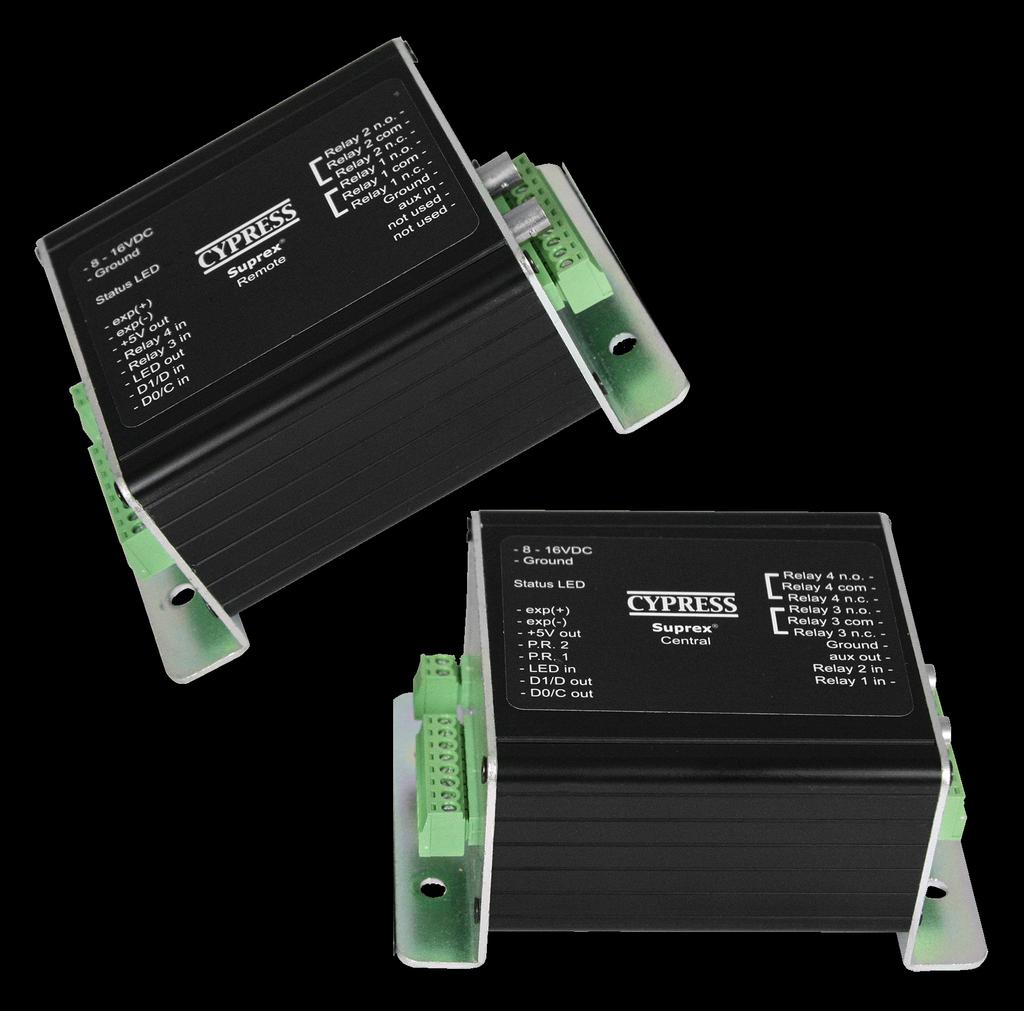
3 External connections and DIP Switch Settings 1-8 to 16 VDC In 2 - Status LED 1 - exp (+) 2 - exp (-) VDC out 4 - Prog Res Prog Res LED In 7 - D1/Data out 8 - D0/Clk out SPX-7400 Central 1- Relay 4 N.O. 2- Relay 4 Com 3 - Relay 4 N.C. 4 - Relay 3 N.O. 5 - Relay 3 Com 6 - Relay 3 N.C Aux out 9 - R2 in 10 - R1 in 1-8 to 16 VDC In 2 - Status LED 1 - exp (+) 2 - exp (-) VDC out 4 - R4 5 - R3 6 - LED out 7 - D1/Data In 8 - D0/Clk In SPX-7400 Remote 1- Relay 2 N.O. 2- Relay 2 Com 3 - Relay 2 N.C. 4 - Relay 1 N.O. 5 - Relay 1 Com 6 - Relay 1 N.C Aux in 9 - Not used 10 - Not used Central Unit Settings DIP Switch #1 OFF See appendix for Expansion module Setup Remote Unit Settings DIP Switch #1 OFF See appendix for Expansion module Setup Dip switch #4 is ON -Disable Pullup resistors Dip switch #4 is ON -Enable Pullup resistors Dip switch #4 is OFF -Enable Pullup resistors Wiegand Wiegand / No Filter Strobed Rising Edge (MR-5) Strobed Rising Edge (Dorad0 644) Strobed Rising (Mag-Tek) Strobed Falling Edge Reserved F2F Switch x 2 x 3 x x 4 x 5 x x 6 x x 7 x x x x = ON Dip switch #4 is OFF -Disable Pullup resistors Wiegand Wiegand / No Filter Strobed Rising Edge (MR-5) Strobed Rising Edge (Dorad0 644) Strobed Rising (Mag-Tek) Strobed Falling Edge Reserved F2F Switch x 2 x 3 x x 4 x 5 x x 6 x x 7 x x x x = ON
4 Quick Reference For Typical Connections SPX-7400 Series Central DC Power Supply +8 to +16 VDC Diagnostic LED Access Control Panel LED In D1/Data Out D0/Clock Out R1 IN R1 Input Controls Strike on Remote See page 10 for other strike control options SPX-7400 Series Remote DC Power Supply +8 to +16 VDC Diagnostic LED R1 N.O. R1 Com R1 N.C. Card Reader LED Out D1/Data In D0/Clock In Door Strike Output
5 Fiber Optic Connections Fiber Optic Interface SPX-7400 Central TX RX Fiber Optic Interface SPX-7400 Remote TX RX
6 Temperature Rating vs Voltage Derating Curve Ambient Temperature (Degrees Celsius) Supply Voltage Temperature/Voltage de-rating curve The Suprex units should be operated with a filtered 12 Volt nominal DC supply. Any voltage between 8 and 16 volts can be utilized by following the temperature /voltage derating curve. Voltage should not exceed 16 VDC under normal operating conditions.
7 Cypress Suprex SPX-7400 Enclosure Dimensions ø0.20 X
8 Cypress Suprex SPX-7400 Series - Setup and Pre-installation Bench Testing: Before installing the units in the field they should be assembled and tested at a convenient Bench top location. This will make it easier to verify / change settings and check operation when both units are visible at the same time. It is also a chance to become familiar with the system if this is the first time using the Suprex system. It is much more difficult to setup and test the units when they are several thousand feet apart. 1. Connect the Remote and Central unit Fiber Optic ports together using a crossover connection using a section of fiber optic cable as shown in the diagram in this manual. 2. Connect a suitable power supply to both units. Each unit should be provided with 8-16 volts DC and a minimum of 500mA. 3. Apply power. After about a short delay, both units Diagnostic LED should indicate communication by illuminating with a periodic Green pulse. 5. Touch a jumper wire from the connection the the Relay 1 input on the Central unit. Relay #1 on the Remote unit should activate with an audible click. A VOM or continuity tester should show the Relay #1 normally open contacts on the Remote unit closing when the Relay #1 input is activated (connected to ground) on the Central unit. 6. Units are shipped from the factory set for the Wiegand data format. If a different format is required set the DIP switch to the required reader and panel format. 7. If a reader and panel is accessible, connect the reader to the Remote unit and the Central unit to the panel and verify that card reads are being accepted by the access control system. If any troubleshooting is necessary, it will be easier to do with both units in close proximity to each other. 8. If Expansion modules are used with the system, refer to the Expansion Module Appendix in this manual. 9. Once these steps are completed, the units are ready for installation it their permanent locations and final commissioning as a system.
9 Cypress Suprex SPX-7400 Series - Status Indicators LED Diagnostic Indicator: The LED Diagnostic indicator provides information on the operational status of the unit. If the units are not communicating, viewing the diagnostic indicator LED s may help to determine the nature of the problem. When the Suprex units are operating correctly and have a valid communication channel between the Remote and Central units, the Diagnostic indicators on each unit will flash green rapidly (2-3 flashed per second). DIAGNOSTIC LED NOT ILLUMINATED: If the LED(s) are not illuminated on the unit(s) then the unit is not getting power or there is an electrical problem. The Diagnostic LED s will be illuminated Red/Green or flashing whenever power is applied. CENTRAL UNIT FLASHING BETWEEN RED/GREEN: With power applied and no communication path between the Remote and Central, the Central unit will flash the diagnostic indicator alternately between Red and Green. REMOTE UNIT ILLUMINATED RED: The Remote unit will diagnostic LED will illuminate solid (not flashing) red if it is not receiving communication from the Central. REMOTE AND CENTRAL UNITS FLASHING BETWEEN RED/GREEN: The Central is not Receiving communication from the Remote.
10 Cypress Suprex F.O. Series - Door Strike and LED I/O Note: The LED and Door Strike operation of the FO Suprex differs from previous Suprex version To activate the relay on the Remote unit, connect as shown below. These connections can be used to allow the Remote relay to operate a DOOR STRIKE, GATE, or other locking hardware. Refer to following pages in this document for details of each I/O operation and connection. There are two relays available for accessory outputs at the Remote end. Either relay can be used to provide the Door Strike or Gate activation function. This example uses Relay 1. Wiring Example - Door Strike Follows LED Suprex Central Access Control Panel LED Signal LED In R1 Input Controls Strike on Remote R1 IN Only Relay and LED Connections are shown for clarity, refer to previous diagrams for Power and Data connections. Wiring Example - Door Strike does not follow LED Suprex Central Access Control Panel N.O. Com LED Signal Strike Signal LED In R1 Input Controls Strike on Remote R1 IN
11 Cypress Suprex F.O. Series - Door Strike and LED I/O The Cypress SPX-7400 provides additional data channels to support access control hardware such as door strikes, tamper alarms, request to exit status, etc. These signals are sent to and from the Remote and Central units without the need to run additional wiring. The accessory control I/O use active low inputs. When the inputs are floating (nothing connected) the associated output will be set to a high level. When the input is set to 0Volts () the input will activate its associated output. All Accessory outputs are Open Collector type and will switch to when activated. Each input will have an associated output. See the following pages for a diagram of each I/O pair.inputs can be tested by making a jumper connection to ground and monitoring the associated output. Suprex Fiber Optic Central Jumper to ground to test Input LED In Red arrow denotes direction of command signal Suprex Fiber Optic Remote Output LED Out
12 Cypress Suprex F.O. Series - Relay Controls Suprex Central Suprex Central Relay 1 IN Input Signal Relay 2 IN Input Signal Red arrow denotes direction of command signal Suprex Remote Relay 2 N.O. Relay 2 Com Relay 2 N.C. Relay 1 N.O. Relay 1 Com Relay 1 N.C. Suprex Remote Contact Outputs Contact Outputs
13 Cypress Suprex F.O. Series - Relay Controls Suprex Central Relay 3 N.O. Relay 3 Com Relay 3 N.C. Relay 4 N.O. Relay 4 Com Relay 4 N.C. Suprex Central Contact Outputs Contact Outputs Red arrow denotes direction of command signal Suprex Remote Suprex Remote Input Signal (5Volts DC Maximum) Relay 3 IN Input Signal (5Volts DC Maximum) Relay 4 IN Relay 3 functions as an Alarm relay and monitors the condition of the communication link between the Central and Remote units. Relay 3 is activated when power is applied and the communication link between the Central and Remote is functioning. Relay 3 will become deactivated (Alarm condition) when either the Relay 3 input on the remote is active OR the Remote unit is unable to communicate with the Central unit. See APP NOTE FOR DETAILS
14 SPX-XXXX Application Note Using Supervised Contacts with the SPX-series Extenders Applies to the following products: SPX-5501, SPX-5601, SPX-5521, SPX-5621, SPX-7400, SPX-7410, SPX-7200, SPX-7500, All RIM series products. This application note describes the connections necessary to convey supervised contact status over a Suprex communication link. The configurations described in this app note should apply to most panels that utilize supervised contacts. When connected as described, the Suprex system will provide a supervised signal to the panel interface by reading the supervised status of the contacts connected to the Suprex Remote unit. Theory of operation: The Access control panel is looking for a certain value of resistance connected to the supervised contact terminals. The Suprex Central unit will provide these resistance values locally at the panel so that the correct supervised status is maintained. At the same time, the Remote unit must maintain supervision of the wires connected to the relays and switches that are connected to the remote access point. The contact supervision is provided by the Remote unit. The Suprex system does this by comparing the value of programming resistor at the Central unit with the resistance seen at the Remote interface terminals. When there is a difference in the two values, the Relay on the Central unit is activated. There are two different examples. One example is monitoring a normally closed contact at the Remote unit, and the other example is monitoring a normally open contact at the Remote unit. In the examples given, a normally closed contact will require a programming resistor of 1K and a normally open contact will require a programming resistor of 2K. Other resistor values can be used but 1K resistors are the most common. Other resistance values will require different value(s) for the programming resistor(s). 2K 1K 8 to 16 VDC In Diagnostic LED exp (+) exp (-) +5 VDC out Prog Res 4 Prog Res 3 LED In D1/Data out D0/Clk out Central Unit Relay 4 N.O. Relay 4 Com Relay 4 N.C. Relay 3 N.O. Relay 3 Com Relay 3 N.C. Aux out R2 in R1 in 1K 1K I1- I1+ I2- I2+ Door N.C. Contact Rex N.O. Contact 1K 1K 1K 1K 8 to 16 VDC In Diagnostic LED exp (+) exp (-) +5 VDC out R4 R3 LED out D1/Data In D0/Clk In Remote Unit Relay 2 N.O. Relay 2 Com Relay 2 N.C. Relay 1 N.O. Relay 1 Com Relay 1 N.C. Aux in Not used Not used
15 SPX-7400 Setup - Using Expansion Modules Before using EXP-2000 Expansion modules with the SPX-7400 system, it will be necessary to perform a short configuration process. This process determines if the 7400 will utilize expansion modules, and if so, how many will be used with the system. Each SPX-7400 link can support up to 7 expansion modules. SPX-7400 units are shipped in the factory default condition. Factory default units will be setup to function as SPX-7400 units without expansion modules. Only communications between the 2 gateway units will be active. Setup Process: 1. With power off, set the DIP switch on the Central unit according to the table below. 2. Apply power. The Diagnostic LED should display a steady Green indication. 3. Remove power Set DIP switch #1 OFF. Any other DIP switches can now be set as required (Reader family/ Pullup resistors). The Central unit is now configured. No expansion module configuration is required for the Remote unit. 4. The expansion modules will need to be setup and correctly addressed. See EXP-2000 manual for details of Expansion module setup and configuration. The Expansion units are addressed, and added to the system as pairs. 5. Connect the Expansion modules into the system as indicated in this wiring diagram. Operation with Expansion Modules: The SPX-7400 system Remote and Central gateway units will operate as a standard pair Suprex units, all of the I/O and data terminals are available for use with readers and access control systems. There are some minor differences in operation when using the expansion modules. Each pair of 1. The Diagnostic LED on the Gateway units will indicate the status of the main (gateway) communication link only. 2. The Alarm relay on the Central Gateway unit will deactivate (indicate alarm condition) when the communication fails between the Gateway units or ANY of the the Remote or Central Expansion units. 3. Paired Expansion units will be functionally similar to the standard SPX-1300 Wiegand Suprex system. Central Unit Configuration Mode Settings " " " Switch " " " Gateway only - No EXP" EXP Pair used "" EXP Pair used" " = ON 0 = OFF 3 EXP Pair used" " EXP Pair used" " EXP Pair used" " EXP Pair used" " EXP Pair used" " See EXP-2000 Manual for further setup instructions
16 Cypress Suprex LYNK Fiber Optic Solution Door / Parking Gate EXP-2000C (8) SPX-74X0R (1) ACS EXP-2000C (4) ACS EXP-2000C (3) EXP-2000C (2) EXP-2000R (2) EXP-2000R (3) EXP-2000R (4) EXP-2000R (8) SPX-74X0C (1) Card Reader Wiegand Data Fiberoptic Link RS-485 Link - Multi-drop
17 Cypress Suprex Series - Wiegand Expansion Module Panel Central interface DC Power Supply +8 to +16 VDC EXP(+) EXP(-) SPX-XXXX Central Access Control Panel LED In D1/Data Out D0/Clock Out R1 IN R1 Input Controls Strike on Remote 8 to 16 VDC In 485(+) 485(-) +5 VDC Out Prog Res 4 Prog Res 3 * LED Input D1/Data/F2F Out D0/Clock Out EXP-2000 Central Unit RLY4 N.O. RLY4 Com RLY4 N.C. RLY3 N.O. RLY3 Com RLY3 N.C. RS232 Out RS232 In Aux Out Relay2 Input Relay1 Input Additional EXP Modules See EXP-2000 Manual for further setup instructions
18 Cypress Suprex Series - Wiegand Expansion Module Reader/Door Remote interface DC Power Supply 8 to 16 VDC In SPX-XXXX Remote EXP (+) EXP (-) R1 N.O. R1 Com R1 N.C. Door Strike Output Card Reader LED Out D1/Data In D0/Clock In 8 to 16 VDC In 485(+) 485(-) +5 VDC Out RLY4 Input (5V) RLY3 * Input (5V) LED Output D1/Data/F2F Input D0/CLK Input EXP-2000 Remote Unit RLY2 N.O. RLY2 Com RLY2 N.C. RLY1 N.O. RLY1 Com RLY1 N.C. RS232 Out RS232 In Aux In N/C N/C Additional EXP Modules See EXP-2000 Manual for further setup instructions
SPX-5000 Series. Operations Manual. Suprex Reader Extender - RF Wireless Interface. RPT GHz Repeater. SPX GHz
 SPX-5000 Series Operations Manual Suprex Reader Extender - RF Wireless Interface SPX-5601 2.4GHz RPT-5651 2.4GHz Repeater SPX-5521 900 Mhz IOX-7621 2.4GHz EXP-2000 SPX-6601 2.4GHz SPX-5000_MAN_082112 This
SPX-7200 Series SPX-7200 EXP Operations Manual. Suprex Reader Extender - Ethernet SPX-7200_MAN_082112
 SPX-7200 Series Operations Manual Suprex Reader Extender - Ethernet SPX-7200 EXP-2000 SPX-7200_MAN_082112 Cypress Suprex SPX-7200 Series Overview This manual covers the operation and setup of the Cypress
Suprex RF Series CYPRESS. Operations Manual. Suprex Reader Extender - RF Wireless Interface EXP SPX Mhz SPX-5521_MAN_0316
 CYPRESS Suprex RF Series Operations Manual Suprex Reader Extender - RF Wireless Interface EXP-2000 SPX-5521 900 Mhz SPX-5521_MAN_0316 Cypress Suprex SPX-5521 Series Overview This manual covers the operation
SPX-7400_SPX-7410_MAN_161028
 Suprex Fiber Optic SPX-7400 & SPX-7410 Suprex Reader-Extender Data Sheet SPX-7400 Series EXP-2000 SPX-7400_SPX-7410_MAN_161028 1 Cypress Suprex SPX-7400 & SPX-7410 Overview The Suprex Fiber Optic SPX-7400
Suprex Fiber Optic. Reader-Extender SPX-7400 SPX Product Manual. Reader-Extender. Manual. SPX-7400 Series EXP Suprex_FiberOptic_MAN_170502
 Suprex Fiber Optic Reader-Extender SPX-7400 SPX-7410 Product Manual Reader-Extender Manual SPX-7400 Series EXP-2000 Suprex_FiberOptic_MAN_170502 Cypress Integration Solutions 30+ Years of Access Control
CYPRESS " " EXP SPX Expansion interface! modules EXP-2000_MAN_0314
 CYPRESS EXP-2000 SPX Expansion interface! modules The EXP-2000 provides additional Door/Panel interface points to most SPX products. The EXP-2000 uses a local RS-485 network through an SPX gateway device.
Suprex RS-485 SPX-7500 Wired Reader-Extender
 Suprex RS-485 SPX-7500 Wired Reader-Extender Product Manual SPX-7500_MAN_181206 Cypress Integration Solutions 35 Years of Access Control Ingenuity CypressIntegration.com 2018 Cypress Computer Systems 1778
Suprex Ethernet SPX-7200 Ethernet Reader-Extender
 Suprex Ethernet SPX-7200 Ethernet Reader-Extender Product Manual 1 SPX-7200_MAN_181206 Cypress Integration Solutions 35 Years of Access Control Ingenuity CypressIntegration.com 2018 Cypress Computer Systems
FDW1000(M,S) OPTICAL WIEGAND, MAGSTRIPE & F/2F DATA EXTENDER INSTALLATION AND OPERATION MANUAL
 OPTICAL WIEGAND, MAGSTRIPE & F/2F DATA EXTENDER INSTALLATION AND OPERATION MANUAL") OPTICAL WIEGAND, MAGSTRIPE & F/2F DATA EXTENDER This manual serves the following ComNet Model Numbers: FDW00M/C FDW00S/C FDW00M/R FDW00S/R EXP0C EXP0R The ComNet FDW00 data extenders provide optical connectivity
OPTICAL WIEGAND, MAGSTRIPE & F/2F DATA EXTENDER This manual serves the following ComNet Model Numbers: FDW00M/C FDW00S/C FDW00M/R FDW00S/R EXP0C EXP0R The ComNet FDW00 data extenders provide optical connectivity
CVX-1300 DataBender! Universal Format Converter!
 CVX-1300 DataBender! Universal Format Converter! User Manual CVX-1300_MAN_0114 Electrical and Mechanical Specifications Physical Temp Aluminum enclosure Size 3.5 x 2.75 x.75 Storage (-55 C to +150 C) Operating
RS232 TO WEIGAND INTERFACE
 RS232 TO WEIGAND INTERFACE The RS232 provides data format and protocol translations of numerous card reader technology outputs into almost any other standard or proprietary format. More than 100 format
CVX-1300 CVX DataBender. Universal Format Converter. User Manual
 CVX-1300 CVX-1300 DataBender Multi-Format Converter DataBender Product Manual Universal Format Converter User Manual CVX-1300_MAN_181217 Cypress Integration Solutions 35 Years of Ingenuity CypressIntegration.com
SIO-7300 CYPRESS. Wiegand / Ethernet converter with General I/O control. SIO-7300!Part 15 Class A SIO-7300_MAN_190108
 CYPRESS Wiegand / Ethernet converter with General I/O control Part 15 Class A _MAN_190108 Electrical and Mechanical Specifications Physical Temp Humidity - Aluminum Enclosure 4.45 x 3.08 x 2.0 ( Each Unit
SPX Supervised Reader Extender. Wiring Diagram and Operators Manual MAN-FA-SPX-1200 V1.03
 SPX-1200 Supervised eader Extender Wiring Diagram and Operators Manual MAN-FA-SPX-1200 V1.03 2005 ypress omputer Systems,Inc. www.cypressworld.com Page 1 Table of ontents Quick eference guides Page 3,4
OSM Features: Field Configurable Reader,I/O to OSDP OSDP to Panel
 OSM-1000 Universal OSDP Interface Module Series Features: Field Configurable Reader,I/O to OSDP OSDP to Panel Interfaces and Formats Wiegand ( 4 to 300 bits) F/2F (Binary, ABA) Strobed ( Wiegand, ABA )
Quick Start Installation Guide
 apc/l Quick Start Installation Guide Version A2 Document Part Number UM-201 May 2010 OVERVIEW The apc/l is an intelligent access control and alarm monitoring control panel which serves as a basic building
INSTALLATION INSTRUCTIONS 921P EntryCheck TM
 80 Avenida Acaso, Camarillo, Ca. 90 (805) 494-06 www.sdcsecurity.com E-mail: service@sdcsecurity.com INSTALLATION INSTRUCTIONS 9P EntryCheck TM The EntryCheck 9P Indoor/Outdoor Keypad is a surface mount
Quantum III. Compact DC Drive Package. Slitter DC Drive Package. Quantum III
 Compact DC Drive Package The delivers a DC drive package that integrates the intelligence of the Mentor II with a space saving design that incorporates many accessories typically required in the North
MR52 READER INTERFACE
 IN IN2 IN3 IN4 INPUTS IN5 IN6 IN7 IN8 C www.mercury-security.com 2355 MIRA MAR AVE. LONG BEACH, CA 9085-755, (562)986-905 FAX (562) 986-9205 MR52 READER INTERFACE Installation and Specifications: This
6222 Two Door Module Technical Operations Manual
 6222 Two Door Module Technical Operations Manual TABLE OF CONTENTS Specifications...3 Overview...4 Operations...5 Custom Access Mode...5 Standard Access Mode...5 Offline Access Mode...5 Offline Memory...5
INSTALLATION INSTRUCTIONS 920P EntryCheck TM
 801 Avenida Acaso, Camarillo, Ca. 93012 (805) 494-0622 www.sdcsecurity.com E-mail: service@sdcsecurity.com INSTALLATION INSTRUCTIONS 920P EntryCheck TM The EntryCheck 920P Indoor/Outdoor Keypad is a surface-mount
UC-2000 Installation Manual Unicorn Computers Technology Limited
 UC2000 Installation Manual Copyright 2003. All rights reserved. Table of Contents Specifications 2 Enclosure for the UC2000 Controller 3 Unicorn Access Control System Configuration 4 UC2000 Controller
MR51e Reader Interface
 J4 J TB6 TB5 TB4 TB3 VIN VO TB2 TB J7 2.75 [69.85] 0.2 [5.08] 2.35 [59.69] J3 MR5e Reader Interface Installation and Specifications. General: www.mercury-security.com 2355 MIRA MAR AVE. LONG BEACH, CA
AC-115 Compact Networked Single-Door Controller Hardware Installation and Programming
 AC-115 Compact Networked Single- Controller Hardware Installation and Programming Copyright 2013 by Rosslare. All rights reserved. This manual and the information contained herein are proprietary to REL,
VertX. V100, V200 and V300. Installation Guide Barranca Parkway Irvine, CA USA. November Rev A.1
 15370 Barranca Parkway Irvine, CA 92618 USA VertX V100, V200 and V300 Installation Guide November 2011 6080-930 Rev A.1. Contents Introduction... 3 Parts List... 3 Product Specifications... 3 Cable Specifications...
INSTALLATION INSTRUCTIONS 920 EntryCheck TM
 801 Avenida Acaso, Camarillo, Ca. 93012 (805) 494-0622 www.sdcsecurity.com E-mail: service@sdcsecurity.com INSTALLATION INSTRUCTIONS 920 EntryCheck TM The EntryCheck 920 Indoor/Outdoor Keypad is a surface-mount
DG-800 Stand-Alone Proximity Reader Instruction Manual
 DG-800 Stand-Alone Proximity Reader Instruction Manual I. Features 1. Memory volume up to 1000+10 proximity cards/tokens and PINs with the programming time up to 0.5 seconds. 2. Access modes: a. Only Proximity
RD-SR2 ACCESS SECURITY PRODUCTS LTD. Proximity Card Reader with Remote Control. User Manual
 RD-SR2 Proximity Card Reader with Remote Control User Manual INTRODUCTION The RD-SR2 is a compact, weather resistant multi-function card reader that can be used as a standalone programmable access control
WRI400 WIRELESS READER INTERFACE
 WRI400 WIRELESS READER INTERFACE Technical Services Training for the WRI400 Launched April 2011 March 12 Technical Services Engineering Support 1 Training Overview WRI400 Description Information Installation
MRC350 Card Capture Reader
 MRC350 Card Capture Reader INSTALLATION GUIDE REF No.: DOC0071 ISSUE: 1.3 6th Aug 2015 2 Contents MRC350 INSTALLATION GUIDE 1. OVERVIEW 1-1 1.1 Card Types and Controller Interfaces 1-1 1.2 Basic Operation
EA500. Installation Instructions Transponder
 EA500 EN Installation Instructions Transponder EA500 Installation Instructions 1.0 Overview EN 2 1.0 Overview The EA500 Transponder is the Security Escort module that provides communications between the
PRT-RDS2 Standard 2 Reader Expander
 PRT-RDS2 Standard 2 Reader Expander Installation Manual CONTENTS Protégé System... Introduction... Reader Expander... Features... Reader Expander Specifications... Protégé System Management Suite... Protégé
CRC220 and CRC221 INSTALLATION GUIDE. REF No.: DOC0014 ISSUE: 09
 CRC220 and CRC221 INSTALLATION GUIDE REF No.: DOC0014 ISSUE: 09 30th July 2015 2 Contents CRC220 & CRC221 INSTALLATION GUIDE 1. Scope 1-1 2. Introduction 2-1 2.1 Features 2-1 2.1.1. PCB Features 2-1 2.1.2.
9212i INSTALLATION. Stand-Alone Keypad. Instructions
 INSTALLATION 9212i Stand-Alone Keypad Instructions Features: 4 Independent Outputs 4 Independent Timers All Outputs Assignable by Code On board 5 Amp Form C Relay 120 Users Remote Triggering Input Keypad
SINGLE READER EXPANSION MODULE
 SINGLE READER EXPANSION MODULE INSTALLATION GUIDE A D C - A C X 1 TR- SINGLE READER EXPANSION MODULE The ADC-ACX1 Single Reader Expansion Module provides a solution for interfacing to a one Wiegand reader
HHR-3150 Series System Handheld Wireless Reader Kit with dual Wiegand output
 HHR-3150 Series System Handheld Wireless Reader Kit with dual Wiegand output Product Manual Applications: Rapid disaster deployment Handheld relay control for security officer empowerment (use for functions
D/E Remote Relay Panel User Guide
 D/E Remote Relay Panel User Guide This manual should remain with the unit. D/E Remote Relay Panel Detailed Specifications...2 Environmental Specs...2 Power Supply Requirements...2 Relay Outputs (8)...2
F6-Fingerprint. Access Control/Reader. User Manual. F6 - Simplified Instruction. (Master Code) # (Factory default:1234) Enter the Programming Mode
 # (Factory default:1234) Enter the Programming Mode") -Fingerprint Access Control/Reader Function Description Enter the Programming Mode - Simplified Instruction Operation (Factory default:1234) Change the Master Code Add Fingerprint User Add Card User Add
-Fingerprint Access Control/Reader Function Description Enter the Programming Mode - Simplified Instruction Operation (Factory default:1234) Change the Master Code Add Fingerprint User Add Card User Add
Secrure door control and I/O expansion. Installation Guide. (ver 1.0)
") Secrure door control and I/O expansion Installation Guide (ver 1.0) www.supremainc.com Contents Product Contents 3 Front Panel Description 4 Rear Panel Description 5 Connectors for External Interfaces
Secrure door control and I/O expansion Installation Guide (ver 1.0) www.supremainc.com Contents Product Contents 3 Front Panel Description 4 Rear Panel Description 5 Connectors for External Interfaces
Two Door Controller GEN-045
 Australian Owned, Designed and Manufactured Two Door Controller GEN-045 Genesis Electronics Australia Pty Ltd www.genesiselectronics.com.au Distributed by: Genesis reserves the right to change or modify
Power Over Fiber USER GUIDE. SYSTEM INSTALLATION INFORMATION Description. The leader in rugged fiber optic technology. RLH Industries, Inc.
 USER GUIDE RLH Industries, Inc. The leader in rugged fiber optic technology. U-145 2018A-0119 Power Over Fiber SYSTEM INSTALLATI INFORMATI Description Our patented Power Over Fiber (PoF) system provides
CA-A480-A Elevator Controller. Reference & Installation Manual
 CA-A480-A Elevator Controller Reference & Installation Manual TABLE OF CONTENTS INTRODUCTION.................................................................. 4 Introduction.............................................................................................
MCX402DR-BRD I/O expander. Operating Manual
 Roger Access Control System MCX402DR-BRD I/O expander Operating Manual Product version: 1.0 Firmware version: 1.0.2.255 Document version: Rev. B Design and application The MCX402DR-BRD is I/O expander
DC3IOB Revision User Guide Updated 3/29/10. Overview
 Revision 080910 User Guide Updated 3/29/10 Overview The is a three axis DC brush motor drive with an integrated PLC. A range of motor drive currents are selectable with jumper blocks. The integrated PLC
Installation Manual for D244X Series 24-volt Power Supplies
 Installation Manual for D244X Series 24-volt Power Supplies D2441-B D2441-C D2443-B D2443-C D2445-B D2445-C D2400 Series 1A 24 volts 1A 24 volts 3A 24 volts 3A 24 volts 5A 24 volts 5A 24 volts Dycon Power
Quick Start Installation Guide
 istar Pro Quick Start Installation Guide Version B0 Part Number UM-069 January 2005 OVERVIEW This guide defines all of the commonly used connection methods to the istar Pro. It outlines how to wire readers
ACTsmart2 Product Range Operating and Installation Instructions
 ACTsmart2 Product Range Operating and Installation Instructions 18-00045 Contents ORDERING INFORMATION......4 INSTALLATION NOTES......5 IMPORTANT......5 PRODUCT SPECIFICATION......5 30 SECOND PROGRAMMING
NetGen Hardware Installation Guide. for NetGen Ethernet Door Controllers
 NetGen Hardware Installation Guide for NetGen Ethernet Door Controllers 0613 Table of Contents BLUEWAVE SYSTEM OVERVIEW...2 THE WI-FI LOCK AND SECURITY COMPANY...2 NETGEN DOOR CONTROLLERS...2 INSTALLATION
January 2013 PRICE SCHEDULE A 2.0. Access Plus Telephone Entry & Access Control
 January 2013 PRICE SCHEDULE A 2.0 Section A4 Date Page Comment 1 1 13 All January, 2013 Price Schedule update. 2 13 13 6 Removed 1812 092 from 1812 145 kit. Added 1812 092 to 1812 147 kit. 2 13 13 9 P/N
MODEL KP-100 ACCESS CONTROL DIGITAL KEYPAD OPERATING INSTRUCTIONS
 MODEL KP-100 ACCESS CONTROL DIGITAL KEYPAD OPERATING INSTRUCTIONS Model KP-100 is a self-contained digital keypad. This keypad is suitable for residential, industrial, and commercial installations. It
Rev Cutler-Hammer Smart Breaker Panel Control Manual
 026-70 Rev 0 6-0-03 Cutler-Hammer Smart Breaker Panel Control Manual 640 Airport Road, Suite 04 Kennesaw, GA 3044 Phone: (770) 425-2724 Fax: (770) 425-939 ALL RIGHTS RESERVED. The information contained
NetAXS-123: One door, compact (plastic) enclosure. NetAXS-123: One door, standard (metal) enclosure with tamper switch and terminal block
 enclosure. NetAXS-123: One door, standard (metal) enclosure with tamper switch and terminal block") Honeywell s web-based access control offering now provides solutions for installations of any size. NetAXS enables users to manage their system anywhere there s an Internet connection with no dedicated
Honeywell s web-based access control offering now provides solutions for installations of any size. NetAXS enables users to manage their system anywhere there s an Internet connection with no dedicated
Stand-alone Proximity Access Control
 Stand-alone Proximity Access Control User Manual INTRODUCTION VIDI-AC-1C is a compact, waterproof stand-alone programmable access control system that provides proximity entry for up to 2000 users. It uses
IEI emerge MicroNode Install and Setup Guide. Contents
 IEI emerge MicroNode Install and Setup Guide Contents Connecting power and the network to the MicroNode... 2 Using Power over Ethernet (PoE)... 3 or... 3 Using a 12 VDC power supply... 3 Connecting and
S125 Multi-Purpose 125 KHz RFID Reader USER MANUAL. 9V/24V DC Operating Voltage, AC (optional) KHz RFID EM4100/2 Cards & Tags
 KHz RFID EM4100/2 Cards & Tags") S125 Multi-Purpose 125 KHz RFID Reader 44 mm USER MANUAL MULTI PURPOSE 84 mm ONLINE & OFFLINE MODE BUILT-IN RELAY 125 KHz RFID EM4100/2 Cards & Tags 9V/24V DC Operating Voltage, AC (optional) 3 Online
S125 Multi-Purpose 125 KHz RFID Reader 44 mm USER MANUAL MULTI PURPOSE 84 mm ONLINE & OFFLINE MODE BUILT-IN RELAY 125 KHz RFID EM4100/2 Cards & Tags 9V/24V DC Operating Voltage, AC (optional) 3 Online
Intelligent Devices IDI 1100 Series Technical Manual
 Intelligent Devices IDI 1100 Series 4411 Suwanee Dam Road, Suite 510 Suwanee, GA 30024 T: (770) 831-3370 support@intelligentdevicesinc.com Copyright 2011, Intelligent Devices, Inc. All Rights Reserved
NS1 Connection Unit Guide
 PURPOSE AND APPLICATION Connection Unit Guide The connection unit is an installation friendly device, which makes it possible to use all features from a central unit. The CU can also be used to connect
Proximity Card and Pin Reader Installation Manual
 Multi Prox Proximity Card and Pin Reader Installation Manual PUBLICATION INFORMATION 60A9 - Draft Release Version 0.1.2 71D0 - Version 1.0.5 CONTENTS Introduction... 1 Legend... 2 Terminology... 2 Mounting...
Page 1 MRK-D-0011, V2.0 Aeroqual SM50 User Guide
 Page 1 Table of Contents User Guide Revision History... 3 Description... 4 1. Operating Instructions... 4 1.1. Power... 4 1.2. Warm Up... 4 1.3. Standard Inputs and Outputs... 4 1.4. Using the Relay Output...
RFID/Digital Access Control Keypad
 R Luminous/ RFID/Digital Access Control Keypad Model:YK-368L-R Germany EMC tested FEATURES AND FUNCTIONS Simple Programming, Easy Operation 3-Operation Mode: ID Card Operation, User Code Operation, ID
Security Management System by Diebold, Inc. LINX System Hardware Installation Guide
 Security Management System by Diebold, Inc. LINX System Hardware Installation Guide INSTALLATION GUIDE LINX Integrated Security System WSD 2000 Weatherized Status Display Table of Contents Introduction
RBR-SB-KTZ001 LAR 2. User Manual
 RBR-SB-KTZ001 LAR 2 User Manual INTRODUCTION KTZ001 is a compact, waterproof stand-alone programmable access control system that provides proximity entry for up to 2000 users. Read both EM and HID card.
7612 Programming Instructions
 7612 Programming Instructions Built-in Proximity reader Read Range 65mm odulation ASK at 125kHz Compatible Cards ALL 26-Bit EM Cards 7612 is a vandal resistant proximity card and keypad access control
The SH8RP Board. Introduction CASI RUSCO
 CASI RUSCO The SH8RP Board Introduction The SoftwareHouse 8RP (SH8RP) board supports devices that employ half duplex RS-485. The SH8RP board will accommodate cable lengths to a maximum distance of 1,000
IBA-7612 Programming Instructions
 IBA-7612 Programming Instructions Built-in Proximity reader Read Range 65mm odulation ASK at 125kHz Compatible Cards ALL 26-Bit EM Cards IBA-7612 is a vandal resistant proximity card and keypad access
Web-based Access Control System. Lower Cost of Ownership
 Web-based Access Control System NetAXS-123 Hybrid Access Control Panel Honeywell s web-based NetAXS controller provides solutions for installations of any size. NetAXS-123 enables users to securely manage
Connecting a Cisco Input Module
 CHAPTER 4 Overview The optional Cisco Input Module (Figure 4-1) is attached to a Cisco Physical Access Gateway or Cisco Reader Module to provide additional connections for up to ten input devices. Each
180 Series Keypad. Handbook. Revision 2.1
 180 Series Keypad Handbook Revision 2.1 Revision History Revision 1.0 Initial release Revision 2.0 Major update with addition of 180-40 Added 180-40 to document and various headings Note regarding unique
PRT-RDE2 Ethernet 2 Reader Expander
 PRT-RDE2 Ethernet 2 Reader Expander Installation Manual PUBLICATION INFORMATION This manual covers firmware versions 1.44 or higher of the Protégé 2 Reader Ethernet Expander when operating on hardware
Web-based Access Control System. Employee access. EMBEDDED Web Browser
 Web-based Access Control System NetAXS-123 Hybrid Access Control Panel Honeywell s web-based NetAXS controller provides solutions for installations of any size. NetAXS-123 enables users to securely manage
716 Converter. Programmable Data Converter
 716 Converter Programmable Data Converter The 716 can perform over 30 different conversions, supporting Rs232, wieigand, magnetic stripe, wieaba, wand emulation, f2f, and others. Flash upgrading allows
2000 Series e/em Style Keypad Installation and Programming Manual
 2000 Series e/em Style Keypad Installation and Programming Manual Document Number: 6054022 Revision: 0 Date: 12/21/06 Table of Contents Table of Contents Section 1: Introduction... 6 1 Product Description...6
ES-600 Ozone Controller Operation Manual
 ES-600 Ozone Controller Operation Manual Questions about your product? Find answers here: Web: www.ozonesolutions.com/es-600 Phone: 712-439-6880 Ozone Solutions OZONE CONTROLLER Model ES-600 Instructions
DC3IOB Revision User Guide Updated 7/12/12. Overview
 DC3IOB Revision 080910 User Guide Updated 7/12/12 Overview The DC3IOB is a three axis DC brush motor drive with an integrated PLC. A range of motor drive currents are selectable with jumper blocks. The
Amano (itrt) Intelligent Twin Reader Terminal INSTALLATION MANUAL
 Intelligent Twin Reader Terminal INSTALLATION MANUAL") MODEL NUMBER: XRT910-0-0-AC-XX XRT920-0-0-AC-XX AMANO itrt Amano (itrt) Intelligent Twin Reader Terminal INSTALLATION MANUAL SPECIFICATIONS Working Environment Plastic Housing... Power Designed to work
MODEL NUMBER: XRT910-0-0-AC-XX XRT920-0-0-AC-XX AMANO itrt Amano (itrt) Intelligent Twin Reader Terminal INSTALLATION MANUAL SPECIFICATIONS Working Environment Plastic Housing... Power Designed to work
High Voltage DC Meter
 High Voltage DC Meter Javelin D PD644 0-300 VDC input NEMA 4X, IP65 front Scale in engineering units Sunlight readable LED display 4-20 ma analog output Two form C 3 A relays option RS-485 serial communications
IPassan Installation guide
 IPassan Installation guide 1 Content 1 Overview... 3 1.1 Features... 3 1.2 Hardware... 3 1.2.1 s... 3 1.2.2 Extra modules... 5 1.3 IPassan manager... 7 2 Installation... 7 2.1... 8 2.1.1 Power supply...
Installation & Operation Guide
 Installation & Operation Guide (Shown with optional Override Board Cover) KMD-5831 Programmable Loop Controller PLC-28 Direct Digital Controller 902-019-04B 1 Introduction This section provides a brief
Quick Start Guide. SEB-710 I/O Expansion board. Introduction
 SEB-710 I/O Expansion board Revision 1.0 - (March, 2011) Saflec Systems (Pty) Ltd Quick Start Guide Introduction The SEB-710 is an I/O expansion device for additional inputs and outputs. It has eight relay
THE BRIDGE. Make any Wiegand device wireless with the Sure-fi Bridge FEATURES. Technology
 THE BRIDGE Make any Wiegand device wireless with the Surefi Bridge *Housing options sold separately. Keep your Wiegand system connected. Fix faulty Wiegand systems quickly and easily with our wireless
HHR-3260 SYSTEM Handheld Wireless Reader Kit with 2 readers and dual Wiegand output
 HHR-3260 SYSTEM Handheld Wireless Reader Kit with 2 readers and dual Wiegand output Applications: Rapid disaster deployment Handheld relay control for security officer empowerment (use for functions such
MR50 READER INTERFACE
 2.75 [69.9] 2.35 [59.7] U1 MR50 READER INTERFAE Installation and Specifications: 1. General: www.mercury-security.com 2355 MIRA MAR AVE. LONG BEAH, A 90815-1755, (562)986-9105 FAX (562) 986-9205 This device
VIDI-AC-2CS Access Controller/ Reader
 VIDI-AC-2CS Access Controller/ Reader User Manual CONTENTS INTRODUCTION 2 INSTALLATION.4 STANDALONE MODE 6 CONTROLLER MODE.11 WIEGAND READER MODE.. 13 ADVANCE APPLICATION..14 1 INTRODUCTION The VIDI-AC-2CS
April 2015 PRICE SCHEDULE A 2.0 Stand-Alone Access Control
 Section A6 This Price Schedule is effective April 1, 2015. Date Page Comment 4-1-15 All April, 2015 Price Schedule update. 5-8-15 3 Removed model 1503. Added models 1509 / 1515 (Pg 15) to the TOC. 8-10-15
GV-AS200 Controller. Hardware Installation Guide
 GV-AS200 Controller Hardware Installation Guide Before attempting to connect or operate this product, please read these instructions carefully and save this manual for future use. 2008 GeoVision, Inc.
VANDAL RESISTANT BACK-LIT WEATHERPROOF ACCESS CONTROL KEYPAD
 VANDAL RESISTANT BACK-LIT WEATHERPROOF ACCESS CONTROL KEYPAD Post Mount Keypad Programming & Installation Manual 1. Connect Power 12V DC to 24V AC/DC to terminals (+) and (-) Post Mount Keypad Quick Start
CDN503 HIGH DENSITY I/O ADAPTER USER GUIDE
 CDN503 HIGH DENSITY I/O ADAPTER USER GUIDE 13050301 (c) Copyright DIP Inc., 1996 DIP Inc. P.O. Box 9550 MORENO VALLEY, CA 92303 714-924-1730 CONTENTS DN503 PRODUCT OVERVIEW 1 DN503 INSTALLATION 1 POWER
TC-9102 Series Surface Mount Temperature Controllers
 TC-9102 Series Surface Mount Temperature Controllers General Description & Applications The TC-9102 Series Temperature Controller offers a versatile solution for a wide variety of applications that may
UNIVERSAL EXPANDER FOR CARD / CHIP READERS INT-R. 1. Features. 2. Installation and start-up
 UNIVERSAL EXPANDER FOR CARD / CHIP READERS INT-R int-r_en 09/11 The INT-R expander interfaces with the INTEGRA and CA-64 alarm control panels, replacing the previously offered CA-64 SR and CA-64 DR expanders.
Integriti 8-32 Zone LAN Expander Module Kit INSTALLATION MANUAL
 Revision 2.1 July. 2014 1 Integriti 8 32 Zone LAN Expander Module Kit P/N: 996005PCB&K For Rev. B PCB. INSTALLATION MANUAL Overview The Integriti 8 Zone Expander Module provides an additional 8 Zone inputs,
721EX Access Controller Installation
 721EX Access Controller Installation 721EX Controller Standalone Controller Specifications Max Card Capacity: 3000 What is included in the box B-Id 721EX controller board RS485/Serial converter USB/Serial
PRT-PX16 16 PGM Output Expander
 PRT-PX16 16 PGM Output Expander Installation Manual CONTENTS Protégé System Introduction... PGM Expander... Features... PGM Expander Specifications... Protégé System Management Suite... Protégé Modules...
LIN FIBER OPTIC BRIDGE
 LIN FIBER OPTIC BRIDGE USER MANUAL (Satellite Module and Bridge Adapter) Version 2.0 2008 Dearborn Group Inc. 27007 Hills Tech Court Farmington Hills, MI 48331 Phone: (248) 488-2080, FAX: (248) 488-2082
I-7520: RS-232 to RS-485. Input: RS-232 protocol Output:RS-485/RS-422 Speed: Self Tuner 'inside, auto switching baud rate, 300~ BPS
 I-7520 RS-232 to RS-485 Converter I-7510 RS-485 Repeater RS-232 RS-485 I-7000 SERIES Common Specifications Isolation voltage: 3000VDC Speed: 1200, 2400, 4800, 9600, 19200, 38400, 57600, 115000 Dual watchdog
INSTALLATION INSTRUCTIONS Model 930 EntryCheck
 SECURITY DOOR CONTROLS 3580 Willow Lane, Westlake Village, CA 91361-4921 (805) 494-0622 Fax: (805) 494-8861 www.sdcsecurity.com E-mail: service@sdcsecurity.com INSTALLATION INSTRUCTIONS Model 930 EntryCheck
AK-21. Digital Keyless Entry System. Installation and Programming Instructions
 AK-2 Digital Keyless Entry System Installation and Programming Instructions (760) 8-7000 USA & Canada (800) 2-587 & (800) 92-02 Toll Free FAX (800) 68-0 www.linearcorp.com CONTENTS COMPONENT LOCATIONS.......................................
Serial Data DIN Fiber Link System
 USER GUIDE RLH Industries, Inc. The leader in rugged fiber optic technology. U-120 2017A-0420 DIN Fiber Link System COMPACT, RUGGED & TEMPERATURE HARDENED Introduction The DIN Fiber Link system transports
119.4 mm. Aux. 3 PNP (Aux., Fault, Weak) 7 PNP (Aux., Fault, Weak & Ch 1-4) 7 PNP (Aux./Mute lamp, Fault, Weak & Ch 1-4) Yes
 7 PNP (Aux., Fault, Weak & Ch 1-4) 7 PNP (Aux./Mute lamp, Fault, Weak & Ch 1-4) Yes") MACHINE SAFETY ACCESSORIES 519 CONTROLLERS GRIDS & POINTS INTERLOCKS E-STOP BUTTONS CONTROLLERS Fiber Optic Four optical channels protect personnel from hazardous equipment and to protect critical tooling
MACHINE SAFETY ACCESSORIES 519 CONTROLLERS GRIDS & POINTS INTERLOCKS E-STOP BUTTONS CONTROLLERS Fiber Optic Four optical channels protect personnel from hazardous equipment and to protect critical tooling
DNETEXT-C CAN Bus Extender, Version 3 User s Manual. Brad Harrison
 DNETEXT-C CAN Bus Extender, Version 3 User s Manual Brad Harrison Although every effort has been made to insure the accuracy of this document, all information is subject to change without notice. Woodhead
EP1501 Intelligent Controller
 J6 BT K K2 TB5 TB 2.35 [59.69] 2.75 [69.85] EP50 Intelligent Controller with Paired Reader Interface for One Physical Barrier Installation and Specifications: www.mercury-security.com 2355 MIRA MAR AVE.