Unpacking and Installing the Flora 2512 UV Printer. Steps 1: Unscrew the 10mm bolts holding the top. Then remove the top and put in a safe place.
|
|
|
- Elvin Scott
- 6 years ago
- Views:
Transcription


 Step 4 Unscrew the 14mm bolts holding the sides.")


1 Unpacking and Installing the Flora 2512 UV Printer Steps 1: Unscrew the 10mm bolts holding the top. Then remove the top and put in a safe place. Step 2: Unscrew 10mm bolts holding the end panels. On the bottom of the end panels are 3-14mm bolts attached to L brackets and frame remove. (We used an automatic screw gun with adaptors for the mm sockets) Step 4 Unscrew the 14mm bolts holding the sides. There are two on each side. Then remove the sides and put in a safe place. Step 5 There is a steel reinforcement across the middle. Unscrew and remove, this will not be needed in the future. Step 6 Remove the outside plastic wrap, then remove the aluminum moisture barrier sheet, and last remove the remaining plastic wrap. Step 7 On top of the bed of the printer are accessories boxes and parts. Remove from the top of the bed and keep in a safe space.

 and clear the area for better understanding of the")


2 Step 8 There are 4 corner braces holding the printer to the skid, at each corner on the bottom of the printer. Remove in no particular order. Step 9 We think it is a good idea to remove all the excess aluminum sheeting (cut it off with a blade) and clear the area for better understanding of the footprint of the machine. Step 10 Take the machine off the crate, use fork lift in the center to lift it and then remove the bottom of the crate. Installing Flora 2512 UV Printer Step 1 Remove the Power cable from right front corner of the printer. Step 2 Install power plug for fit check and install air line to printer.


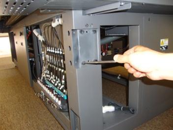
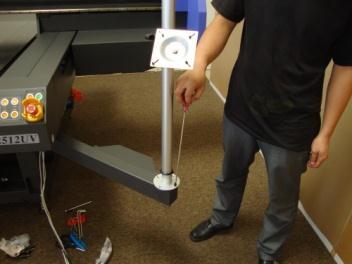
3 Step 3 There is a large white tie wrap holding the print head steady at the right side of the carriage. Cut the tie wrap to allow the print head to move. Then unscrew the black knob on top of the print head, it must be loosened and remove white foam from beneath the print head. Step 4 Relocate the print head stop from the present position to far end of the right hand side of the carriage beam. Step 5 At each corner of the printer there are leveling legs. Lower all 4 adjustable legs until the machine is perfectly level. Check with carpenter s level left to right and front to back. Step 6 Remove wrapping from stand for keyboard, monitor to attach to right front leg of the machine. Install horizontal arm to leg with 4 Allen head screws. Then install the silver vertical post with 4 phillips head screws.


4


5 Step 7 Slip keyboard platform over silver post and tighten with black T handle. Attach monitor stand and slip it over silver post. USB Cable for connecting computer printer is located inside the computer compartment and printers USB port is on the right hand side of the same compartment. Step 8 Next is to isolate the vacuum hold down motors (2). They are located under the table in the center at the rear. From the factory the motors are bolted solid to the frame. Remove solid bolts and replace with rubber stand offs. 4 rubber stand offs on each motor. This places the motors on rubber suspension and reduces noise & vibration. This is hard work in very close quarters. Take your time and be careful. Step 9 At this moment you are ready to plug in the printer to the power outlet and turn on the system power and main power by flipping on switches on the right side of the printer, and press the Power button located underneath the printer control panel. Test the cariage movement by manually moving it using printer controll buttons.


6 Installing computer and software for Flora 2512 UV Step 1 Connect your monitor, keyboard and mouse to your computer and power the computer, do not connect it to the printer at this moment. Insert the CD supplied with the machine labeled Photo Print 6.1V2, for the necessary installation. The screen will prompt you with Choose Setup Language window, select your language.then click OK, the InstallShield Wizard will start. Accept the License Agreement. Step 2 Select features and installation folder and click next for installation and setup to start. Step 3 The Install Manager window will come up. Please enter password supplied with the software, and click Done. Select Install to desktop and lastly Finish to complete installation
 folder.")


7 Installing the Flora Driver Step 1 Insert the FloraPrint Driver CD. From the list of Folder under Print Driver, select corresponding machine model (eg: PP2512UV) folder. Then double-click the setup file. Files will be extracted and Welcome window will appear. Click Next, select your language and click OK. Select the model, click Next. Step 2 If software does not detect the installation path correctly you have will have to click on browse and find path manually. Installation folder should be C\Program files\sai\photoprint Flora Edition. Click OK and then Next to complete the installation. Step 3 Before connecting your computer to the printer make sure your printer is powered down. Connect the printer and computer using USB cable provided and then power the printer back. Step 4 Open PhotoPrint Flora Edition, if this is first time you are opening the software it will prompt you to add your setup. Select printer model you have. For example, Flora 2512 UV 8 colors (C,M,Y,K,Lc,Lm,W,V) select 2508VKM, select Flora port, click Finish.


8 Carriage assembly gap adjustment Step 1 Open PhotoPrint Flora Edition, go to Setup and Default Job Properties. On the Printer Option Tab click on the Test Print button to open Test Print tool bar. Move Carriage to the Right Move Carriage up or down Step 2 Using controls on the tool bar move carriage assembly to the right hand side and then remove front cover. Lower the assembly down until height detector sensor touches the Flat Bed. Use Metric Feeler gauge to measure the gap. Gap should be between 1.5mm and 2mm. Steps 3 To adjust the carriage assembly gap loosen two black Philips screws which hold height sensor bracket. To make carriage assembly gap smaller move the bracket down, to make the gap bigger move the bracket up. Tighten the screws and test the gap by moving carriage up and then lowering it down, adjust if needed by repeating steps above. Ink Loading and Print Head Installation


9 Step 1: Removing Carriage Cover. Loosen the allen screw from the carriage height adjustment knob and remove the knob. Undo five philips screws which hold carriage cover, and carefully remove the cover. NOTE: Under the carriage cover is print board, the most important and expensive part of the printer be very careful handling it. Step 2: Remove the cap from the bottom of the black ink tube that comes out if the ink subtank, turn the positive pressure valve to positive position, press prime button, to purge any ink or solvent out of the secondary ink tank. Turn the negative pressure valve to negative position and replace tube cap. Repeat for remaining ink tanks. Step 3 Loading the inks. On the right side of the machine are ink bottles, pour ink into corresponding ink bottles, BE VERY CAREFULL NOT TO LOAD INK INTO WRONG BOTTLE. Close ink bottles. Step 4 To load inks into secondary holding tanks, turn the printer on, open PhotoPrint Flora Edition go to Setup, Default Properties, Printer Option Tab click on Advanced button then go to System Tab and check Ink Supply check box. This will send command to Ink Pumps to load ink from the bottles into Ink Sub-Tanks.


10 Print Head Installation Step 1 Print Head assembly. Remove antistatic bag from the white print head box. Open the bag and remove the head. Remove protective clear tube from print head inlet and outlet ports. Step 2 Open head hardware box and remove Ink Inlet Tube, the one with the white disc filter. Connect it to Print Head Inlet port. The inlet port is one on the right hand side. Connect Ink Bleeding Tube to the left, bleeding, port. Make sure the ink tubes slide all the way to the end. Ink bleeding port Inlet port Step 4 Installing print head cable connector. Remove cable connector bag from the hardware box. First install two gold color screws on to the print head, than install print head connector on to the head, tighten with two silver philips screws. Step 6 Installing the head. Start by removing back and front head fixation screws. Remove the white plastic head protector, place head into the head opening on the carriage. Replace the back fixation screw but do not tighten all the way. For easier head alignment we suggest that you push the head all the way to the back and left with one hand and then completely tighten


11 the front fixation screw. Make sure Mechanical Alignment Lock screw is loose at this point. Step 7 First we need to flush print heads and ink tubing for any ink or transport solution. Load the syringe with the flush solution. First flush the tubing, connect syringe to the print head inlet tube disc filter, uncap the outlet tube and push some solution through the tube. Cap the outlet tube, and gently push some solution through the head till you see clean flash solution coming out of the print head nozzles. Step 8 Connecting ink tubing to the print head. Make sure machine is powered on so that negative pressure will keep ink from leaking. Remove black cap from the disk filter. Very important to do next step very fast: remove ink tube cap and connect ink tube to the disc filter by pushing tube on to the connector and twisting it to the right for approximately half circle. Taking too long to connect could result in ink backing up into negative pressure tank. Step 9 To remove on any air or flash solution out of the tubing and print head you will need to bleed the tubing and the print heads. Turn the negative pressure valve to positive setting (right). Uncap the outlet ink tube, lower it down below the head level and press Ink Prime button to flush the head of any air or flush solution. Turn the valve back to negative pressure setting (left)
.")


12 and cap the outlet tubing, make sure you cap the tube while holding it below the head level. Step 10 Bleed the Print Head. Turn the negative pressure valve to positive setting (right). Press the prime button till you see ink coming out of the print head nozzles. Repeat for all heads. Step 10 Connecting Flat Data cable. When connecting the data cable it is important to connect correct head to correct connection on the Print Control Board. In the 8 head configuration follow this order: K - JB1, C - JB3, M JB5, Y - JB7, LC - JB9, LM JB11, W JB13, V-JB15. First insert the end of the data cable into connector on the Print Control Board, make sure the connector guide fits into connector slot, than connect the other end of the cable to the Print Head Connector. After all Flat data cables are connected do last check on connection. Make sure that all cable as firmly in place. You will notice that one side of the Flat Data Cable is red, make sure red side is to the back of the connectors on PCB and on the Print Head Connector.
13
Removal and Installation8
 8 Screw Types 8-4 Top Cover Assembly 8-5 Left Hand Cover 8-6 Right Hand Cover 8-10 Front Panel Assembly 8-14 Left Rear Cover 8-15 Right Rear Cover 8-16 Extension Cover (60" Model only) 8-17 Media Lever
Toucan LT board printer
 Toucan LT board printer Setup and Operating instructions Unpack the Toucan LT board printer as you would any Toucan LT. Follow all cautions associated with installing a standard Toucan LT. Change in wash
VJ-1614 INSTALLATION MANUAL
 VJ-6 INSTALLATION MANUAL Please read this manual before using Thank you for purchasing a MUTOH product. This manual explains the steps for unpacking, mounting and basic installation before using the MUTOH
VJ-1604 INSTALLATION MANUAL
 Please read this manual before using Thank you for purchasing a MUTOH product. This manual explains the steps for unpacking, mounting and basic installation before using the MUTOH Full-color inkjet printer
Calibration Guide. Software Interface Introduction. In Control Pad Tab. Add: add print file. Setting: set parameters and calibrate
 Calibration Guide Software Interface Introduction In Control Pad Tab Add: add print file Setting: set parameters and calibrate Online: online / offline switch Home: carriage goes to home position Down
KM-4800w. Installation Guide
 KM-4800w Installation Guide TABLE OF CONTENTS page 1 Installation Requirements 2 2 Unpacking 3 2. 1 Unpacking 3 2. 2 Confirmation of Accessories 5 3 Leveling the Machine 7 4 Setup of the Roll Deck 9 5
VJ-1618 INSTALLATION MANUAL
 Please read this manual before using Thank you for purchasing a MUTOH product. This manual explains the steps for unpacking, mounting and basic installation before using the MUTOH Full-color inkjet printer
QUICK START GUIDE. Android or Windows Tablet. 1 Tower PC. Mount the RazorGage to your Own Table. Assembling the RazorGage ST with RazorGage Table
 QUICK START GUIDE Android or Windows Tablet If you have a Tablet Style Interface (PC or Android) then skip this step. 1 Mount monitor and attach legs to control tower using hardware provided and place
VJ-1304 INSTALLATION MANUAL
 Please read this manual before using Thank you for purchasing a MUTOH product. This manual explains the steps for unpacking, mounting and basic installation before using the MUTOH Full-color inkjet printer
MUTOH EUROPE N.V. Tel.:32-(0) Fax:32-(0)
 Fax:32-(0)") MUTOH INDUSTRIES LTD. Tel.:8-(0)-570-00 Fax:8-(0)-570-00 E-mail:ibd@mutoh.co.jp http://www.mutoh.co.jp MUTOH AMERICA INC. Tel.:-80-968-777 Fax:-80-968-7990 E-mail:sales@mutoh.com http://www.mutoh.com MUTOH
MUTOH INDUSTRIES LTD. Tel.:8-(0)-570-00 Fax:8-(0)-570-00 E-mail:ibd@mutoh.co.jp http://www.mutoh.co.jp MUTOH AMERICA INC. Tel.:-80-968-777 Fax:-80-968-7990 E-mail:sales@mutoh.com http://www.mutoh.com MUTOH
Additional Help For additional installation instructions and videos, please visit our website at What s Included
 Model 400, 40, 40 Additional Help For additional installation instructions and videos, please visit our website at www.current-usa.com What s Included Each LOOP Marine Bundle Kit includes: Item A B C D
Installing the Dye Sublimation Printing System
 Installing the Dye Sublimation Printing System Instructions for Epson D120 Printer ArTainium UV+ D120 Bulk Ink Feeder ITec Economy Heat Press STX11 / STX20 Index Page Contents 1 Contact Information 2 Unpacking
Z-Truck (Vertical Moving) Z-truck Flag. Y-Truck (Horizontal Moving) FIGURE 1: VIEW OF THE Z-TRUCK. Flexshaft Assembly
 Z-truck Flag. Y-Truck (Horizontal Moving) FIGURE 1: VIEW OF THE Z-TRUCK. Flexshaft Assembly") Replacing the LCD Cable To remove and replace the LCD Cable you will need the following tools: #2 Phillips screwdriver (magnetic tip preferred) Socket wrench with 10mm socket Removing the Side Panel 1.
Replacing the LCD Cable To remove and replace the LCD Cable you will need the following tools: #2 Phillips screwdriver (magnetic tip preferred) Socket wrench with 10mm socket Removing the Side Panel 1.
Service Manual. Version 1.1. User Manual. Copyright 2014 Anajet LLC
 Service Manual Version 1.1 User Manual Copyright 2014 Anajet LLC Table of Contents Cover... 3 Chapter 1: Introduction... 4 Capter 2: Adjustments... 5 2.1 Carriage Belt Tension... 5 2.2 Table Belt Tension...
AstroJet TM M2 Quick Start Guide
 AstroJet TM M2 Quick Start Guide Step 1 Remove Printer and Accessories from packaging. Place Printer on a flat, even surface. Step 2 Remove Service Station Transport Tab 1. Open Top Cover. 2. Open Print
Setup Guide. Confirming the Installation Space. Installation space (W x D x H) 70.5 x 66.3 x 61.5 inches (1790 x 1684 x 1560 mm) 23.
 70.5 x 66.3 x 61.5 inches (1790 x 1684 x 1560 mm) 23.") Introductory Information Setup Guide ENGLISH Read this manual before attempting to operate the printer. Keep this manual in a handy location for future reference. Caution Instructions in this Setup Guide
Introductory Information Setup Guide ENGLISH Read this manual before attempting to operate the printer. Keep this manual in a handy location for future reference. Caution Instructions in this Setup Guide
Installation Guide. Retrofit Kit for USB Ready Intraoral Systems
 Installation Guide Retrofit Kit for USB Ready Intraoral Systems Table of Contents Wall-Mount Retrofit Kit... 2 Introduction... 2 Connecting the Articulating and Horizontal Arm Cables... 2 Installing the
Assembly and Set-Up Instructions
 HP DesignJet 500 and 800 Series Printers Assembly and Set-Up Instructions 1. Check the Contents of the Package This Assembly and Set-Up Poster Day-to-day package containing Using Your Printer documentation
think big, print huge
 think big, print huge quick start guide Table of Contents a Receiving and uncrating 5 b bed level & z home 11 c Loading filament 19 d SOFTWARE 23 e Setup 23 f preparing a print 26 g printing on gigabot
Required Tools. Ford Transit Connect J4075 with R16 Tracks TRANSIT CONNECT 69 RAIL IBI. Marker. 7/16 / 9/16 / 1/2 Wrench.
 IBI Required Tools INSTRUCTION MANUAL Marker 7/16 / 9/16 / 1/2 Wrench Drill with 3/8 Drill Bit Allen Key Ford Transit Connect J075 with R16 Tracks Part # J075 Rails 96 Bars 55 [ ] BLACK WHITE SILVER [
TIME WIZARD MULTI CLOCK DIVIDER BUILDING GUIDE
 TIME WIZARD MULTI CLOCK DIVIDER BUILDING GUIDE Table of Contents 0. Components List + Tools 0. PCB Sides 03. PCB Assembly 04_. Diode N448 04_. Laying Resistors 04_3. Capacitors 04_4. Quartz 04_5. 78L05
CAVS USA Inc. Quick Start Manual For Karaoke Jukebox CAVS JB-99RX. Version and up
 Quick Start Manual For Karaoke Jukebox CAVS JB-99RX Version 1.0.0.261 and up 1 Contents Page 1. Unpacking 3 2. Installation 4 2.1 Touch Screen monitor 4 2.2 Mixer-Amplifier 5 2.3 Microphone 5 3. Booting
Warning! To prevent any bodily damage read entire manual before starting.
 Warning! To prevent any bodily damage read entire manual before starting. DANGER To prevent possible electrical shock during an electrical storm, do not connect or disconnect cables or station protectors
Printing Your First Page. Attaching the Paper Support. Plugging in the Printer. Checking the Printer
 Printing Your First Page Attaching the Paper Support Checking the Printer Plugging in the Printer Installing the Ink Cartridges Installing the Printer Software Connecting the Printer 4011307 XXX-00 Attaching
Océ User manual. Océ CS2024. Quick Start Guide
 Océ User manual Océ CS2024 Quick Start Guide Océ Technologies B.V. Copyright 2005, Océ-Technologies B.V. Venlo, The Netherlands. All rights reserved. No part of this work may be reproduced, copied, adapted,
 1 Contents Welcome... 3 Cutter Parts... 4 Front View... 4 Detail of Carriage Arm... 5 Right Side View... 6 Left Side View... 7 Back View... 8 Detail of Pinch Roller (Back View)... 9 Control Panel... 10
MultiPASS F50 Setup Instructions
 MultiPASS F50 Setup Instructions Step 1: Unpack the F50 MFP 1. Carefully remove all items from the box. Step 2: Set up the F50 MFP 1. Remove shipping tape and protective shipping materials. 2. Open the
VJ-1624 INSTALLATION MANUAL
 VJ-6 INSTALLATION MANUAL Please read this manual before using Thank you for purchasing a MUTOH product. This manual explains the steps for unpacking, mounting and basic installation before using the MUTOH
Replacing the Encoder Strip
 6-1-11. Replacing the Encoder Strip The following describes the procedure for replacing the Encoder Strip. Refer to the diagram below for identifying the parts and their positions. (The numbers shown in
CBT LW 4-PUMP ADD-ON INTERNATIONAL INSTALLATION GUIDE
 CBT LW 4-PUMP ADD-ON INTERNATIONAL INSTALLATION GUIDE 2 General information This manual contains technical information regarding Bayer SeedGrowth Equipment. Please read and understand these instructions
Getting Started. Read Me First. series. Photo Printer
 Photo Printer series Getting Started Read Me First Make sure to read this manual before using the printer. Please keep it in hand for future reference. Symbols Used in This Document Instructions including
Further Information can be found at
 Below is a step by step guide to assembling the Hurricane-Rig. Remember that this is a precision optical instrument. Excessive force can bend critical parts. If treated well it should give many years of
Toshiba Satellite A215 S4697 Screen
 Toshiba Satellite A215 S4697 Screen Replacement When your computer screen is cracked or does not work anymore, it may need a new screen. Written By: Carlos ifixit CC BY-NC-SA www.ifixit.com Page 1 of 15
USER GUIDE 3D PluraView 2,5k und 4k
 USER GUIDE 3D PluraView 2,5k und 4k Table of Contents 1. Delivery 2. Explanation 3. Unpack the monitor 4. Mounting the monitor 5. Install the 3D PluraView on the workstation 6. Fine tuning the monitors
Gateway Profile 4 service guide
 Gateway Profile 4 service guide Customizing Troubleshooting Contents Replacing Components in Your Gateway Profile 4.................. 1 About this guide.....................................................
6 x 6 Peltier-Thermostatted Multicell Holder Series II Accessory
 6 x 6 Peltier-Thermostatted Multicell Holder Series II Accessory Overvoltage Category II Pollution Degree 2 Equipment Class III Safety information Introduction Before using this accessory, you must read
Calibration and Maintenance
 Epson DX5 X 1 Printhead Calibration and Maintenance 31 st Jan., 2013 Version V3.0 1 Contents Chapter 1: Computer Requirement...3 Chapter 2:Installation...4 Chapter 3:Characteristic...5 Chapter 4:Board
Float Pod Installation Manual
 Float Pod Installation Manual TABLE OF CONTENTS What to do before receiving the pod..page 3 Receiving the pod...page 5 Installing UV..Page 9 Control Box. Page 12 Intercom....Page 14 Audio.. Page 16 Pod
G12/G12x USER S MANUAL
 G12/G12x USER S MANUAL TABLE OF CONTENTS SECTION 1 SLIDE CONFIGURATION SECTION 2 SLIDE CONFIGURATION ACCESSORIES SECTION 3 TABLETOP CONFIGURATION SECTION 4 TABLETOP CONFIGURATION ACCESSORIES SECTION 5
CAMARA Computer Guide Setup
 Computer Guide Setup Chapter 1. Before You Start Chapter 2. Unpacking Chapter 3. Assembly Chapter 4. Power Problems Chapter 5. Switch On Chapter 6. Login Chapter 7. Logout Chapter 8. System Shutdown CAMARA
Written By: John Sutton
 Replacing the fan on your HP g7-2275 dx. Written By: John Sutton ifixit CC BY-NC-SA www.ifixit.com Page 1 of 20 INTRODUCTION Laptop cooking your lap? This guide will walk you through replacing your fan.
Ioline CrystalPress. Quick Start Guide
 Ioline CrystalPress Quick Start Guide The Quick Start Guide is intended to help a new user of the Ioline CrystalPress get everything setup and running quickly. Please note that there are important notices,
Getting Started. Read Me First. series. Canon Inkjet Premium Photo Printer. 1 Preparation...P.1. Install the Print Head... P.3
 Canon Inkjet Premium Photo Printer series 1 Preparation...P.1 Getting Started Read Me First Symbols Used in This Document Prohibited actions. Instructions including important information. In this guide,
PrismJET DTx Quick Start Guide
 PrismJET DTx Quick Start Guide The following items are included in an accessory kit for your printer: USB Cable 110V Power Cord JetPRO 13/JetCUT Setup DVD User Guide CD Phillips Screwdriver Unpacking the
Ioline 300/350HF System
 Quick Start Guide Ioline 300/350HF System User Notice Trademarks Ioline is a trademark of Ioline Corporation. Other product names, logos, designs, titles, words or phrases mentioned within this publication
Getting Started. Read Me First. series. Photo Printer
 Photo Printer series Getting Started Read Me First Make sure to read this manual before using the printer. Please keep it in hand for future reference. Contents 1 Preparation 2 Turn the Power On 3 Install
OPERATING INSTRUCTIONS:
 List OPERATING INSTRUCTIONS: Preparation For Installation, Product Identification Charging The Batteries ing And Adjusting The Lift Mounting Head s Brackets Mounting Clamps And Quick-Locking Arms Installation
Removing and Replacing Parts
 Removing and Replacing Parts Preparing to Work Inside the Computer Recommended Tools Screw Identification System Components Hard Drive Fixed Optical Drive Media Bay Devices Memory Modules Mini PCI Card
MD-BSL15W / SPRING-LOADED TWIN-ARM. For ( cm) LCD desktop computer. User Manual
 LCD desktop computer. User Manual") MD-BSL15W / SPRING-LOADED TWIN-ARM MONITOR mount For 15 27 (38.1 68.6 cm) LCD desktop computer User Manual Thank you for choosing Gabor. The Gabor MD-BSL15W mounts two 15 27 (38.1 68.6 cm) LCD computer
MD-BSL15W / SPRING-LOADED TWIN-ARM MONITOR mount For 15 27 (38.1 68.6 cm) LCD desktop computer User Manual Thank you for choosing Gabor. The Gabor MD-BSL15W mounts two 15 27 (38.1 68.6 cm) LCD computer
Photo Parts List T-Jet 1 & 2
 Bulk system Description: Chain system and hoses are part of the bulk system. That connects to cartridges and to ink bottles on the outside. The system is held up by a metal bracket and screwed on to the
Upgrading and Servicing Guide
 Upgrading and Servicing Guide Copyright Information The only warranties for Hewlett-Packard products and services are set forth in the express statements accompanying such products and services. Nothing
Start Here. Remove all tape and lift display. Locate components USB
 HP Photosmart 2600/2700 series all-in-one User Guide Start Here 1 USB Important: Do not connect the USB cable until this guide instructs you to or the software may not install properly. If you have problems
Assembly and Setup Manual
 M-11 Series Copyboard/C-11 Series Captureboard Assembly and Setup Manual This is the installation and assembly manual for the M-11 series/c-11 series. To the Customer Specialized techniques are required
INSTALLATION INSTRUCTIONS
 INSTALLATION INSTRUCTIONS 19 20 21 01 07 22 23 13 10 12 08 17 18 11 02 14 15 04 03 16 WELCOME PARTS LIST Thank you for purchasing this HealthPoint Technology Cabinet from Humanscale! Before you begin installing
SATALIGHT ASSEMBLY INSTRUCTIONS
 SATALIGHT ASSEMBLY INSTRUCTIONS SATALIGHT STAND AND PROJECTOR INSTALLATION It is our recommendation, before installing the satalight, to have the IT staff install SMART Notebook software on the computer
Assembly Instructions
 Assembly Instructions Flat Screen Garage End User & IT Computer Cable Management May 2013 nylon zip-tie #2 (for computer wires) rear-access beam door (open) Figure 1 nylon zip-tie #1 (for #1 motor control
Q2 XBee Handheld Controller Assembly Guide
 Q2 XBee Handheld Controller Assembly Guide Copyright Quantum Robotics Inc. Q2 Controller V1.0 1 Parts List: The kit comes with 14 individual bags. 1. Case Top and Bottom 2. Case Screw Package containing:
Dell Inspiron XPS and Inspiron 9100 Service Manual
 Dell Inspiron XPS and Inspiron 9100 Service Manual Dell Inspiron XPS and Inspiron 9100 Service Manual Before You Begin Memory Module, Mini PCI Card, and Devices System Components Subwoofer Bluetooth Card
Continuous Ink Supply System. for EPSON R285. Installation Instruction. For ST Prefilled Version
 Continuous Ink Supply System for EPSON R285 Installation Instruction For ST Prefilled Version This Version of the Continuous Ink Flow System comes with Prefilled Cartridges and Auto Reset Chips. You just
Upgrading and Servicing Guide
 Upgrading and Servicing Guide Copyright Information The only warranties for Hewlett-Packard products and services are set forth in the express statements accompanying such products and services. Nothing
2.2. Facilities Requirements
 2.2. Facilities Requirements Facilities requirements for the alpha-se system are listed in Table 2-1 and the system dimensions are given in Figure 2-1. As shown in Figure 2-2, the preferred clear work
1 Introduction. 2 Mounting the RP3 USB interface
 1 Introduction The new ROWPERFECT3 Rowing Simulator is equipped with the, also new, RP3 USB Interface. Using this interface and the accompanying software, one can record training sessions and store over
Océ CS9060. User s Guide. Eco Solvent
 Océ CS9060 User s Guide Eco Solvent Océ CS9060 - INSTALLATION GUIDE Thank you for purchasing a Océ CS9060 Eco Solvent Printer! Please read this manual before using the printer, otherwise things might go
When you are ready to build your computer you will have the following materials to work with.
 Copyright 2009 BOSMA Enterprises Chapter 3 Putting the Computer Together When you are ready to build your computer you will have the following materials to work with. 1. One motherboard. 2. One ribbon
Zebra XiII-Series Printer Quick Reference Guide
 Zebra XiII-Series Printer Quick Reference Guide Contents Media and Ribbon Loading...67 Media Loading...67 Ribbon Loading...70 Operator Controls...72 Front Panel Keys...72 Front Panel Lights...72 Calibration...74
Important! Save the box and shipping materials for transporting the MultiPASS in the future.
 Step 1: Unpack the MultiPASS 1. Carefully remove all items from the box. Remove these items from the documentation package: Quick Start Guide, the Canon Creative for MultiPASS CD-ROM, Registration card,
Assembly Instructions for #5630 Medication PalWOW
 Assembly Instructions for #5630 Medication PalWOW Before assembling, please familiarize yourself with all the parts and check to make sure you have all the parts as listed below. A B A & B - The box in
Installing the Printer Software
 4 Printing Your First Page Attaching the Paper Support 7 1 Checking the Printer 6 2 Plugging in the Printer 3 Installing the Ink Cartridges 5 Installing the Printer Software Connecting the Printer 4012581-00
Oracle <Insert Picture Here>
 Slide 1 Oracle Slide 2 WZT-6509 version B Sun Fire Nehalem and Westmere Rack-Mount Server Installation and Replacement Welcome to the installation and replacement
Product Overview. Features
 APCF1 Model Tripod Product Overview The Ravelli APCF1 is a Professional Quality Carbon Fiber Tripod providing a solid base for high-end photographic equipment. This model is a mix of carbon fiber and magnesium
Shop Fox Fence Kit Installation Instructions:
 Shop Fox Fence Kit Installation Instructions: Please note this installation kit is designed solely for installation on a Shop Fox Classic Fence. Accurate Technology manufactures kits for other saw fences
Removal and Installation 8
 Removal and Installation 8 8 Introduction 8-2 Service Calibration Guide to Removal and Installation 8-4 Window 8-8 Covers and Trims 8-12 Rear Tray 8-31 Rear Cover 8-32 Media Lever 8-33 Media Lever Position
Written By: senordingdong
 Installation of the UniMac V4 adapter into the Apple imac Intel 17". This enables the usage of non OEM LCD panels, and offers an otherwise unavailable Full HD upgrade. This used for repair of the common
Written By: Walter Galan
 Replace a cracked screen on your iphone 4S. Written By: Walter Galan ifixit CC BY-NC-SA www.ifixit.com Page 1 of 32 INTRODUCTION Use this guide to replace the screen on your iphone 4S. After successfully
TABLE OF CONTENTS SECTION 1 TABLETOP CONFIGURATION SECTION 2 TABLETOP CONFIGURATION ACCESSORIES SECTION 3 SLIDE CONFIGURATION
 S6 USER S MANUAL TABLE OF CONTENTS SECTION 1 TABLETOP CONFIGURATION SECTION 2 TABLETOP CONFIGURATION ACCESSORIES SECTION 3 SLIDE CONFIGURATION SECTION 4 SLIDE CONFIGURATION ACCESSORIES SECTION 5 RACK MOUNT
Manual for MantraJet 1100 CD/DVD auto-printer
 Manual for MantraJet 1100 CD/DVD auto-printer Rev 1.03 September 7, 2010 Table of contents Specifications...3 Unpacking MantraJet 1100...4 Quick installation reference MantraJet 1100...7 Installation of
Installation Instructions
 Model: Page: 1 of 6 EEOS130A Sun Machine 450 EL Unit Setup Installation Instructions INSTALLATION MUST BE PERFORMED BY QUALIFIED EQUISERV PERSONNEL ONLY INSTALLATION OVERVIEW: The Installation Instructions
VELOCI-T IMPORTANT GUIDELINES. 1) In order to keep your Veloci-T running well, you must print at least 15 shirts per week*.
 In order to keep your Veloci-T running well, you must print at least 15 shirts per week*.") VELOCI-T IMPORTANT GUIDELINES 1) In order to keep your Veloci-T running well, you must print at least 15 shirts per week*. 2) We highly recommend that you print at least 36 shirts within 7 days of setting
VELOCI-T IMPORTANT GUIDELINES 1) In order to keep your Veloci-T running well, you must print at least 15 shirts per week*. 2) We highly recommend that you print at least 36 shirts within 7 days of setting
2 x Dynamic Arms on 135 Post with C-Clamp
 Installation Guide AWMS-2-D13-C 2 x Dynamic Arms on 135 Post with C-Clamp COMPONENT CHECKLIST RANGE A AWM-LC Post Clamp B AWM-AD Dynamic Arm (x2) C AWM-P13 135 Post D AWM-FC C-Clamp CONTENTS C-Clamp Page
MantraJet 1100 CD/DVD autoprinter Operator s manual
 MantraJet 1100 CD/DVD autoprinter Operator s manual Rev 1.00 May 7, 2008 Table of contents 1. Specifications.. Page 2 2. Unpacking you MantraJet 1100 Page 3 3. Using your autoprinter for the first time.
Written By: Walter Galan
 imac Intel 21.5" EMC 2428 CPU Replacement Replace the CPU in your imac Intel 21.5" EMC 2428. Written By: Walter Galan ifixit CC BY-NC-SA www.ifixit.com Page 1 of 33 INTRODUCTION Use this guide to upgrade
ip3600 series Getting Started =Read Me First= Photo Printer
 Photo Printer ip3600 series Getting Started =Read Me First= Make sure to read this manual before using the printer. Please keep it in hand for future reference. Symbols The following symbols are used to
HP Photosmart c3180 Main Circuit Board Replacement
 HP Photosmart c3180 Main Circuit Board Replacement Replacing a faulty main circuit board. Written By: Jim ifixit CC BY-NC-SA www.ifixit.com Page 1 of 26 TOOLS: Spudger (1) T10 Torx Screwdriver (1) ifixit
REFILLABLE CARTRIDGE SYSTEM FOR THE EPSON STYLUS PRO 7800 & 9800
 REFILLABLE CARTRIDGE SYSTEM FOR THE EPSON STYLUS PRO 7800 & 9800 Thank you for purchasing an Ink2image bulk ink feed system. You have just taken the first step to enjoying the cost saving and superior
Afinia Label L901 Label Printer Quick Start Guide
 Afinia Label L901 Label Printer Quick Start Guide Ver. 1.1 Page 2 Step 1 Remove Printer and Accessories from packaging Items included: Printer USB cable One ink set (CMYKK) Quick Start Guide Network cable
OLPC XO-4 Touch Touchpad Controller Replacement
 OLPC XO-4 Touch Touchpad Controller Replacement This guide will walk through replacing a touchpad. Written By: Theodore Tsanakas ifixit CC BY-NC-SA www.ifixit.com Page 1 of 13 INTRODUCTION Use this guide
Installation Guide for Mazak Mazatrol M - Plus, M-2, M32, T-Plus, T2
 1 Installation Guide for Mazak Mazatrol M - Plus, M-2, M32, T-Plus, T2 Tsubis Part Number: LCD12-0046 Power Down 1. Power down the controller. 2. Power down the complete machine by turning off the rear
DUAL-ARM MONITOR MOUNT For in. ( cm) desktop computer monitors
 desktop computer monitors") LeviTouch DM-502 DUAL-ARM MONITOR MOUNT For 15 27 in. (38.1 68.6 cm) desktop computer monitors User Manual Thank you for choosing Gabor. The Gabor Dual-Arm Desktop Mount can securely support two monitors
LeviTouch DM-502 DUAL-ARM MONITOR MOUNT For 15 27 in. (38.1 68.6 cm) desktop computer monitors User Manual Thank you for choosing Gabor. The Gabor Dual-Arm Desktop Mount can securely support two monitors
To connect the AC adapter:
 Replacing the AC Adapter Replacing the AC Adapter 3 Plug the power cord into a wall outlet. The power indicator turns on. To connect the AC adapter: Connect the power cord to the AC adapter. Power indicator
INSTALLATION GUIDE 02-ES ESTC
 02-ES7341-47 01-140316-01 01-140251-01 01-140162-01 01-140296-01 01-140220-01 01-ESTC01-02 01-140305-01 3.0mm Galvanised Fixed Strap M8 x 35mm Broaching Stud Z/P M8 x 25mm x 1.6mm washer Z/P M8 Nylon Insert
Dell Latitude V710/V740 Service Manual
 Dell Latitude V710/V740 Service Manual Dell Latitude V710/V740 Service Manual Before You Begin Preparing to Work Inside the Computer Recommended Tools Computer Orientation Screw Identification System Components
Peel/Rewind Upgrade Kit
 Peel/Rewind Upgrade Kit Installation Instructions This kit includes the parts and documentation necessary to install the Peel/Rewind upgrade kit on the following printers: ZM400 ZM600 Read these instructions
* IMPORTANT * REGISTERING YOUR MACHINE
 * IMPORTANT * REGISTERING YOUR MACHINE Thank you for your purchase of the Keyline 994 Laser. Before continuing with machine setup and use, please complete the following; COMPLETE PRODUCT REGISTRATION FORM
Eaton LCD Lift Flat Panel Display System. Installation Guide
 Eaton LCD Lift Flat Panel Display System Eaton LCD Lift Flat Panel Display System Installation Guide Copyright 2011 Eaton Corporation, Worcester, MA, USA. All rights reserved. Information in this document
Quick Reference Guide Important Adjustment Program Utilities for Your Fast T-Jet 3
 Quick Reference Guide Important Adjustment Program Utilities for Your Fast T-Jet 3 (User s of Windows Vista OS- The Adjustment Program described in here and in Chapter 7 of your User s Manual must be run
OnePlus 5 Screen and Digitizer Assembly Replacement
 OnePlus 5 Screen and Digitizer Assembly Replacement Follow this guide to replace the screen and digitizer for the OnePlus 5. This replaces the screen as well as the frame it is attached to. Written By:
Section. Service & Maintenance. - Core & Hard Disk Drive (HDD) - Amplifier - Monitor - UPS - Dollar Bill Acceptor - Fan Filter G - 1
 - Amplifier - Monitor - UPS - Dollar Bill Acceptor - Fan Filter G - 1") Section G Service & Maintenance - Core & Hard Disk Drive (HDD) - Amplifier - Monitor - UPS - Dollar Bill Acceptor - Fan Filter G - 1 Core Removal Core & HDD 1. Open the door. 2. Perform shutdown procedure.
Section G Service & Maintenance - Core & Hard Disk Drive (HDD) - Amplifier - Monitor - UPS - Dollar Bill Acceptor - Fan Filter G - 1 Core Removal Core & HDD 1. Open the door. 2. Perform shutdown procedure.
DIGITAL OBSERVATION GUARD LOW PROFILE PAN TILT KIT USER MANUAL
 DIGITAL OBSERVATION GUARD LOW PROFILE PAN TILT KIT USER MANUAL Version 2.1 June 4, 2013 0 Table of Contents Low Profile Pan Tilt Kit Description... 3 Low Profile Pan Tilt Unit Basic Operation... 4 Mounting
Artisan Technology Group is your source for quality new and certified-used/pre-owned equipment
 Artisan Technology Group is your source for quality new and certified-used/pre-owned equipment FAST SHIPPING AND DELIVERY TENS OF THOUSANDS OF IN-STOCK ITEMS EQUIPMENT DEMOS HUNDREDS OF MANUFACTURERS SUPPORTED
Ink Cartridge and Print Head Maintenance Manual
 Ink Cartridge and Print Head Maintenance Manual Hewlett Packard D135/145/155/175 CP1160/Color Copier 610 And other printers with similar cartridge design. Contents Page 3 4 5 6 7 8 9 10 12 15 21 25 26